


G118
Weidmuller Ltd.
10 Spy Court
Markham, ON L3R 5H6
Tel: (905)475-1507
Fax: (905)475-5855
Weidmuller Inc.
821 Southlake Blvd.
Richmond, VA 23236 U.S.A.
Tel: (804)794-2877
Fax: (804)794-0252
ISO 9001 Registered
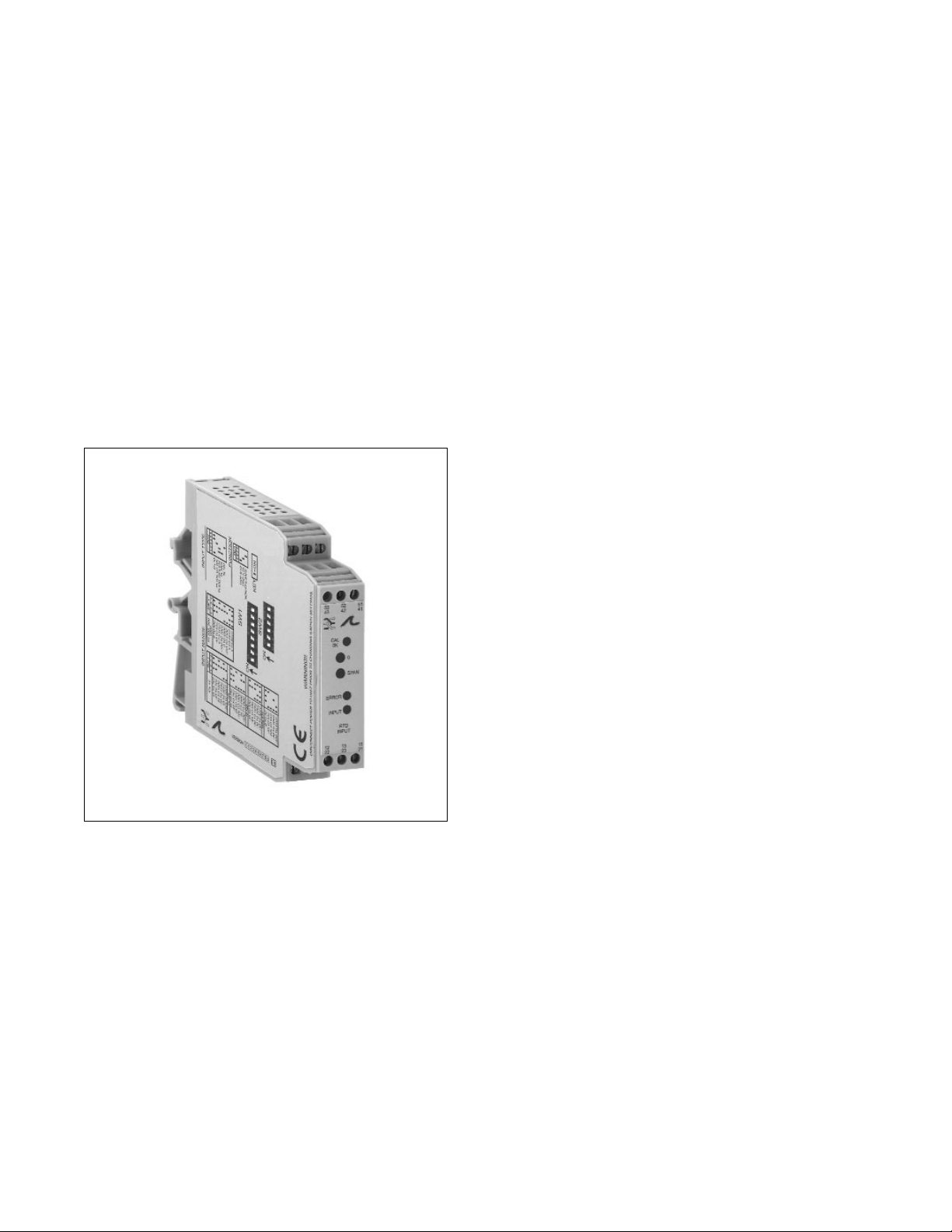
Electronic Interface Modules
G118 Ultra SlimPak®
RTD Input, Field Configurable Limit Alarm
• field configurable via DIP switches for different inputoutput combinations
• provides relay contact closure(s) at a preset
RTD/resistance input level
• field configurable input ranges for platinum, nickel and
copper RTDs
• setpoints programmable HI or LO and failsafe or nonfailsafe
• LED trip and input indicators
• flexible power supply accepts 9 to 30Vdc
• ASIC technology for high reliability
• CSA approved, UL recognized, CE marked
Description
Diagnostic LEDs
Output
Operation
Dynamic Deadband
The Ultra SlimPak G118 is a DIN rail mount, RTD input limit alarm with dual setpoints and two contact
closure outputs. The field configurable input and alarm functions offer flexible setpoint capability. There are
up to eight temperature ranges available for each RTD type to ensure accuracy and maximize setpoint
resolution. The G118 is configurable as a single or dual setpoint alarm, with HI or LO trips and failsafe or
non-failsafe operation. Also included are adjustable deadbands (1% to 5% of full scale input) for each
setpoint and a flexible DC power supply which accepts any voltage between 9 and 30Vdc.
The G118 is equipped with three front panel LEDs. The first is a dual function LED labeled IN (input). This
green LED indicates line power and input signal status. Active DC power is indicated by an illuminated LED.
If this LED is off, check DC power and wiring connection. If the input signal is more than 110% of full scale,
the LED will flash at 8 Hz. Below -10%, the flash rate is 4 Hz. Two red LEDs indicate the relay state for each
setpoint. An illuminated red LED indicates the tripped condition.
The G118 is equipped with two SPDT (form C) relays, rated at 120Vac or 28Vdc at 5 amperes. Each of
these relays is independently controlled by the field configurable setpoint and deadband.
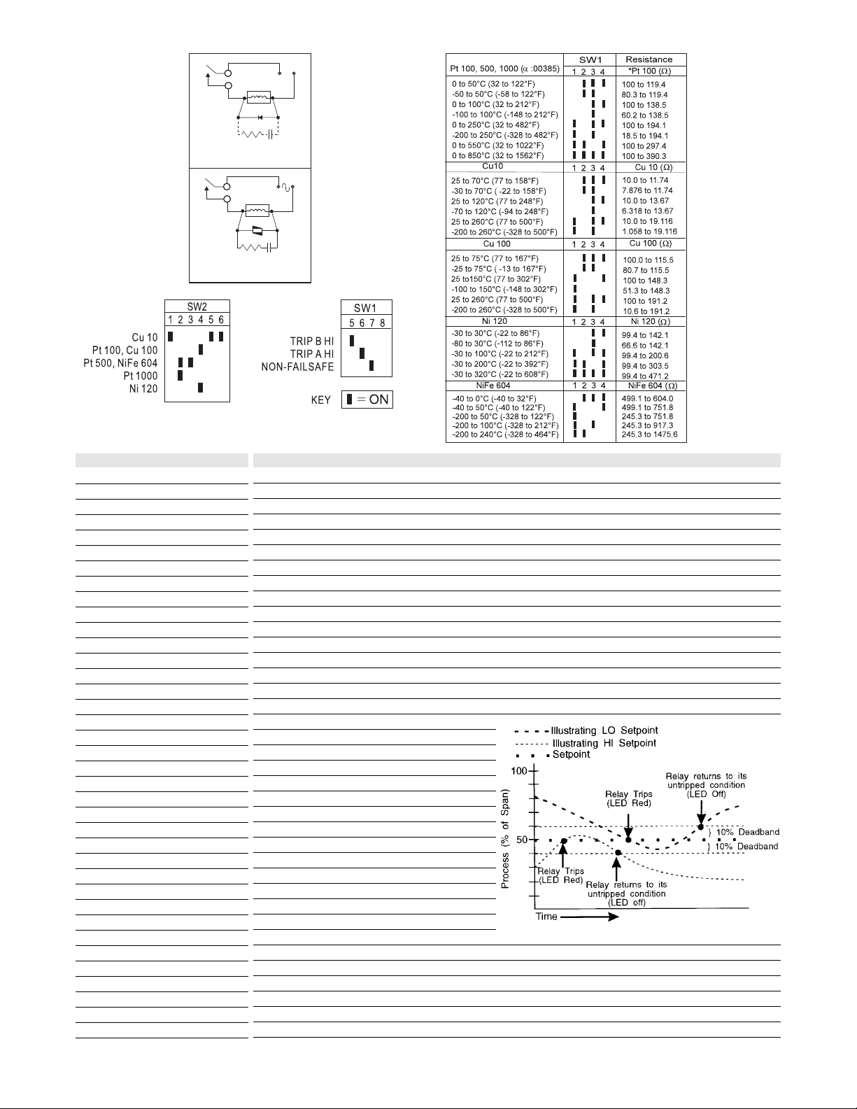
The field configurable G118 limit alarm setpoints
can be configured for HI or LO, failsafe or nonfailsafe operation. Each of the setpoints has a
respective HI or LO dead-band. In a tripped
condition, the setpoint is exceeded and the
appropriate red LED will illuminate. The trip will
reset only when the process falls below the HI
deadband or rises above the LO deadband (see
Figure 1). For proper deadband operation the HI
setpoint must always be set above the LO
setpoint. In failsafe operation, the relay is
energized when the process is below the HI
setpoint or above the LO setpoint (opposite for
non-failsafe). In the failsafe mode, a power failure
results in an alarm state output.
LSI circuitry in the G118 prevents false trips by repeatedly sampling the input. The input must remain beyond
the setpoint for 100 milliseconds, uninterrupted, to qualify as a valid trip condition. Likewise, the input must
fall outside the deadband and remain there for 100 milliseconds to return the alarm to an untripped
condition. This effectively results in a "dynamic deadband" - based on time- in addition to the normal
deadband.
Figure 1
Note: resistance
values for
Pt500(M) and
Pt1000(M) are 5
and 10 times the
resistance value
of Pt100(M),
respectively
Relay
Tabele 1: RTD input type switch
settings (SW2 - 1 through 6)
Tabele 2: Setpoint function switch
settings (SW1 - 5 through 8)
Table 3
Input range
switch settings
(SW-1 through 4)
Conta cts
(optional)
Figure 2: DC Inductive Loads
Relay
Conta cts
Figure 3: AC Inductive Loads
Power
+
-
Load
Diode
47 ohm
0.1uF
1/2W
Film
Power
Load
MOV
47 ohm
0.1uF
1/2W
Film
 Loading...