


en Operating instructions
4-digit temperature and frequency |
|
display with analogue-value output |
|
and threshold monitoring |
15 |
fr Mode d'emploi
Indicateur de température et de fréquence à 4 caractères, avec sortie des valeurs analogiques et surveillance des seuils 25
es Instrucciones de empleo
Indicador de temperatura y frecuencia
de 4 dígitos con salida analógica del valor
y monitorizado de valor límite |
49 |
PMX400/TMP 61001001/00/01.08

en PMX400/TMP
Contents
Operation |
16 |
|
|
Connections |
18 |
|
|
Calibration |
20 |
|
|
Setup Sequence |
22 |
|
|
15

en PMX400/TMP
Power
Supply
Temperature
Sensor Inputs
°C, °F or mV |
Analogue Output |
|
(Optional) |
||
|
||
|
Alarm 1 |
|
|
(Optional) |
|
|
Alarm 2 |
|
|
Alarm 3 |
|
|
(Optional) |
|
|
Alarm 4 |
• Operation
Warning: Check the power supply against the model number before applying power to the instrument.
Reviewing the setup
For review mode, disconnect security link and press PGM. A 10 s timeout applies for review mode.
Changing the setup
For set-up mode, connect security link and press PGM. The software version will be displayed. If you wish to continue, press PGM again within 10 s.
Clearing tripped alarms
You can acknowledge a tripped alarm by simply pressing the key for that channel.
16
Siren and Group alarms
Channel four has two additional alarms types:
•Siren alarm, which you clear by acknowledging all tripped alarms
•Group alarm, which will only clear when you have acknowledged all tripped alarms and all the trip conditions have cleared (and are outside the deadband)
Sensor break alarms
You can set channel one up as a sensor break alarm, which is triggered if the thermocouple input is open circuit or if any of the RTD sensor legs are disconnected.
Displaying the alarm setpoints
To check a setpoint, simply press the key for that alarm.
If the display shows A1=OC when you press the alarm channel one button, you know it is set up as a sensor break alarm.
If the display shows A4=Sr or A4=gr when you press the alarm channel four button, you know it is set up as a siren or group alarm.
Adjusting the alarm setpoints
To change a setpoint, press the PGM key while the value is still on display. You will then be able to change the value using the arrows and save the change using the ENT key. Note that setpoint security must disabled for this to work.
Viewing the Cold Junction temperature
To view the CJC temperature, hold down the @ key and then press
PGM.
Temperature range limits
Choosing a smaller displayed temperature range improves the resolution for the analogue outputs. However it also limits the range for setpoint and display values. So, unless you are using the analogue outputs, you should choose the maximum range. This will give sufficient resolution for effective alarm and display operation.
17

• Connections
Terminal |
Signal |
|
|
|
|
|
1 |
Neutral / – |
|
|
|
Power supply |
|
2 |
Live / + |
|
|
|
||
|
|
|
|
|||
3 |
Output + |
|
|
|
|
|
4 |
Current – |
|
|
|
Analogue output |
|
|
|
|
(/AO option only) |
|||
|
|
|
|
|
|
|
5 |
Voltage – |
|
|
|
|
|
6 |
Security Link |
|
|
|
Link to allow access to the set-up |
|
|
|
|
|
|
|
|
7 |
Security Link |
|
|
|
mode (normally not connected) |
|
|
|
|
|
|||
|
Thermocouple inputs (via CJC Board) |
RTD inputs |
Millivolt inputs |
|||
8 |
8 |
9 |
10 |
11 |
Not used |
Not used |
9 |
|
|
|
|
||
|
|
|
|
|
|
|
10 |
|
|
|
|
B |
mV input – |
11 |
|
--ve |
+ve |
|
Bsense |
mV input + |
12 |
|
mark |
A |
Not used |
||
|
|
|
|
White |
|
|
13 |
Normally Closed |
|
|
|
||
14 |
Common |
|
|
|
Alarm Channel One |
|
|
|
|
(/4RO option only) |
|||
|
|
|
|
|
|
|
15Normally Open
16Normally Closed
17 |
Common |
Alarm Channel Two |
|
(/4RO option only) |
|||
|
|
18Normally Open
19Normally Closed
|
|
Alarm Channel Three |
|
10 |
Common |
||
(/4RO option only) |
|||
|
|
21Normally Open
22Normally Closed
23 |
Common |
Alarm Channel Four |
|
(/4RO option only) |
|||
|
|
||
24 |
Normally Open |
|
|
|
|
|
18

Mounting Dimensions
92.0 mm (+0.8/-0.0 mm)
CUTOUT
45.0 mm (+0.6/-0.0 mm)
GASKET  18.0 mm
 PANEL THICKNESS Max 18.0 mm
19

• Calibration
The PMX400/TMP is factory calibrated. Once calibrated the PMX400/ TMP will operate with any sensor type or range, and any output type or range, without recalibration. You should not have to recalibrate the instrument before installation.
Equipment requirements
•A suitable millivolt source (accurate to 5 μV or better)
•An accurate digital multimeter (accurate to 0.05 mV and ±0.1 μA)
•A Pt100 Rtd simulator (accurate to 0.05 ˚C)
Terminal Connections for calibration
Calibration Stage |
Signal type |
Terminal |
|
|
|
|
|
milliVolt inputs |
Millivolt source (+) |
11 |
|
|
|
||
Millivolt source (–) |
10 |
||
|
|||
CJC Circuit |
Millivolt source (+) |
9 |
|
|
|
||
Millivolt source (–) |
10 |
||
|
|||
|
|
|
|
|
Rtd simulator B |
10 |
|
RTD Inputs |
Rtd Simulator Bsense |
11 |
|
|
Rtd Simulator A |
12 |
|
|
|
|
|
Analogue Current Output |
mA output + |
3 |
|
|
|
||
mA output – |
4 |
||
|
|||
Analogue Voltage Output |
V output + |
3 |
|
|
|
||
V output – |
5 |
||
|
|||
|
|
|
Summary
There are four stages to calibrating the PMX400/TMP
•Calibrate the millivolt inputs
•Calibrate the CJC input
•Calibrate the RTD input
•Calibrate the analogue outputs
20

Note: the analogue output calibration sequence is not shown if the analogue output is disabled.
You can calibrate each stage in sequence or skip sections by pressing the PGM button.
When the |
Action/Description |
|
display shows |
||
|
||
Put the instrument in setup mode and scroll through the main menu |
||
CALIB |
Press ENT to enter calibrate mode |
|
ECALn |
Press ì or Å and then ENT to select millivolt input calibration (or PGM to skip) |
|
E=0 |
Apply a 0.00 mV signal and press ENT |
|
E=10 |
Apply a 10.00 mV signal and press ENT |
|
E=20 |
Apply a 20.00 mV signal and press ENT |
|
E=40 |
Apply a 40.00 mV signal and press ENT |
|
E=80 |
Apply a 80.00 mV signal and press ENT |
|
E=200 |
Apply a 200.00 mV signal and press ENT |
|
jCALn |
Press ì or Å and then ENT to select CJC input calibration (or PGM to skip) |
|
CJ=0 |
Apply a 0.00 mV signal to the CJC input and press ENT |
|
Cj=60 |
Apply a 600.0 mV signal and press ENT |
|
rCALn |
Press ì or Å and then ENT to select Rtd input calibration (or PGM to skip) |
|
-200C |
Set the RTD simulator to -200 ˚C and press ENT |
|
0C |
Set the RTD simulator to 0 ˚C and press ENT |
|
400C |
Set the RTD simulator to 400 ˚C and press ENT |
|
800C |
Set the RTD simulator to 800 ˚C and press ENT |
|
OCALn |
Press ì or Å and then ENT to select analogue output calibration (or PGM to skip) |
|
|
Measure the current (mA) output. |
|
I=0 |
Adjust using the ì and Å keys until the output is at 0.00 mA. |
|
|
Press ENT. |
|
I=20 |
Adjust using the ì and Å keys until the output is at 20.00 mA. |
|
Press ENT. |
||
|
||
|
Measure the output voltage. |
|
E=0 |
Adjust using the ì and Å keys until the output is at 0.00 V. |
|
|
Press ENT. |
|
E=10 |
Adjust using the ì and Å keys until the output is at 10.00 V. |
|
Press ENT. |
||
|
||
CALIB |
You are now back in the main menu, press PGM |
|
SAvE |
Instrument will save the new values and return to run mode |
21
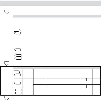
• Setup Sequence
Menu |
Setting |
Options |
Description |
ì |
Å |
ENT |
|
v1.11 |
|
S/W Version, e.g., 1.11 Note: this guide is for versions 1.10 to 1.19 |
|
||||
1(. |
|
|
|
|
|
|
|
|
|
|
|
|
|
|
|
|
|
|
|
Input menu |
|
|
|
|
|
|
IP=_1 |
J type thermocouple |
|
|
|
|
|
|
IP=_2 |
K type thermocouple |
|
|
|
|
|
|
IP=_3 |
N type thermocouple |
|
|
|
|
%.4 |
|
IP=_4 |
T type thermocouple |
Previous |
Next |
|
|
Input |
IP=_5 |
E type thermocouple |
Accept |
|||
|
|
|
|||||
|
1(. |
type |
IP=_6 |
B type thermocouple |
|
|
|
|
|
|
|
||||
INP |
|
|
IP=_7 |
S type thermocouple |
|
|
|
|
|
IP=_8 |
R type thermocouple |
|
|
|
|
|
|
|
|
|
|
||
|
|
|
IP=_9 |
milliVolts |
|
|
|
|
|
|
IP=10 |
Pt100 RTD |
|
|
|
|
1(. |
Damping |
dF= |
Introduces the damping factor |
- |
- |
Next |
|
|
|
|
|
|
|
|
|
%.4 |
factor |
2 |
Value e.g., 2 |
Inc |
Dec |
Accept |
|
1(. |
|
(minimum = 1 / maximum = 99) |
||||
|
|
|
|
|
|
||
|
|
|
|
|
|
|
|
1(. |
|
|
|
|
|
|
|
Display menu
|
%.4 |
Display |
degC |
Degrees Celsius |
|
|
|
|
degF |
Degrees Fahrenheit |
Toggle |
Accept |
|||
|
1(. |
units |
|||||
|
|
(not shown for milliVolt inputs) |
|
|
|
||
|
|
|
|
|
|
|
|
dISP |
|
|
dHI= |
Display range upper limit |
- |
- |
Next |
|
1(. |
Display |
870.0 |
Select the highest value available |
Toggle |
Accept |
|
|
|
dLO= |
Display range lower limit |
- |
- |
Next |
|
|
|
range |
|||||
|
%.4 |
|
|
|
|
|
|
|
|
-220.0 For information only |
|
- |
Accept |
||
|
1(. |
|
|
||||
1(. |
|
|
|
|
|
|
|
22

Setup Sequence (continued)
|
|
|
|
Alarms 1- 4 enable/disable menu |
|
|
|
|
|
%.4 |
|
1 & 2 |
A12y |
Alarms one and two enabled |
Toggle |
Accept |
|
AL1-4 |
1(. |
|
Select |
A12n |
Alarms one and two disabled |
|||
|
|
|
|
|||||
|
|
|
|
|
|
|||
|
|
|
|
|
|
|
|
|
|
1(. |
|
3 & 4 |
A34y |
Alarms three and four enabled |
Toggle |
Accept |
|
|
|
Select |
A34n |
Alarms three and four disabled |
||||
|
|
|
|
|
|
|||
%.4 |
|
|
Press PGM to skip to analogue output menu. |
|
|
|
||
|
|
|
|
|
|
|||
|
|
|
|
|||||
|
|
Alarm channel setup menus (repeated for each enabled alarm channel) |
|
|||||
|
%.4 |
|
Coil state |
A1nE |
Normally energised |
Toggle |
Accept |
|
|
1(. |
|
A1nd |
Normally de-energised |
||||
|
|
|
|
|
|
|||
|
|
|
|
A1=lO |
Low alarm |
|
|
|
|
|
|
Alarm |
a1=HI |
High alarm |
|
|
|
|
|
|
a1=OC |
Open circuit alarm (ch 1 only) |
Toggle |
Accept |
||
|
|
|
type |
|||||
|
|
|
A4=Sr |
Siren alarm (ch 4 only) |
|
|
|
|
|
|
|
|
|
|
|
||
AL1 |
|
|
|
A4=gr |
Group alarm (ch 4 only) |
|
|
|
1(. |
|
Note: the |
following settings are not shown for group siren or sensor break alarms |
|||||
|
|
|
Setpoint |
SP1= |
Introduces setpoint value |
- |
- |
Next |
|
|
|
50.0 |
Any value witin the display limits |
Inc |
Dec |
Accept |
|
|
|
|
|
|||||
|
|
|
Deadband |
db1= |
Introduces deadband value |
- |
- |
Next |
|
|
|
10.0 |
Any value within the display span |
Inc |
Dec |
Accept |
|
|
|
|
|
|||||
|
|
|
Timer |
dl1= |
Introduces timer delay |
- |
- |
Next |
|
%.4 |
|
|
|
|
|
|
|
|
|
delay |
0 |
(0s to 4200 s) |
Inc |
Dec |
Accept |
|
|
1(. |
|
||||||
|
|
|
|
|
|
|
|
|
1(. |
|
|
|
|
|
|
|
|
|
|
|
|
|
|
|||
AL2 , AL3 , AL4 |
|
|
Alarm Channel two, three and four setup menus |
|
|
|||
1(. |
|
|
|
|
|
|
|
|
All Alarms Submenu (reset mode and setpoint security settings)
|
%.4 |
Reset |
nor |
Automatic reset |
Toggle |
Accept |
|
A-ALL |
1(. |
sequence |
reS |
Manual reset |
|||
|
|
||||||
|
|
|
|
|
|||
|
%.4 |
Setpoint |
SECy |
Change setup mode only |
Toggle |
Accept |
|
|
1(. |
security |
SECn |
Change in run or setup mode |
|||
|
|
|
|||||
1(. |
|
|
|
|
|
|
23
Setup Sequence (continued)
|
|
|
Analogue Outputs setup menu |
|
|
|
||
|
%.4 |
Output |
AOPy |
Enabled |
Toggle |
Accept |
||
|
1(. |
select |
AOPn |
Disabled |
||||
|
|
|
|
|||||
|
|
Note: the |
following settings are not shown if the analogue outputs are disabled |
|||||
|
|
Type |
OP=I |
Current (mA) output |
Toggle |
Accept |
||
|
|
OP=E |
Voltage output |
|||||
|
|
|
|
|
|
|||
|
|
|
Inl= |
Input that gives minimum output |
- |
- |
Next |
|
AOP |
|
Input |
0.0 |
e.g., 0.0 °C |
Inc |
Dec |
Accept |
|
1(. |
range |
InH= |
Input that gives maximum output |
- |
- |
Next |
||
|
||||||||
|
|
|
100.0 |
e.g.,100.0 °C |
Inc |
Dec |
Accept |
|
|
|
|
OPL= |
Output signal zero level |
- |
- |
Next |
|
|
|
Output |
4.00 |
e.g., 4.00 mA |
Inc |
Dec |
Accept |
|
|
|
range |
OPH= |
Output signal full scale |
- |
- |
Next |
|
|
|
|
20.00 |
e.g., 20.00 mA |
Inc |
Dec |
Accept |
|
|
%.4 |
Output |
OP=d |
Direct acting output |
Toggle |
Accept |
||
|
1(. |
Action |
OP=r |
Reverse acting output |
||||
|
|
|
|
|||||
1(. |
|
|
|
|
|
|
|
|
|
|
|
|
|
|
|
|
|
CalIB |
|
|
Calibration Menu (press PGM to skip) |
|
|
|
||
SAVE |
|
|
Instrument is saving the changes to the setup |
|
|
|
||
24

fr PMX400/TMP
Table des matières
Fonctionnement |
26 |
|
|
Connexions |
29 |
|
|
Etalonnage |
31 |
|
|
Séquence de configuration |
34 |
|
|
25
 Loading...