


WI-MOD-945-E
802.11 DSSS/OFDM
Wireless Ethernet Modem &
Device Server
User Manual
Version 2.16
Read and Retain for
Future Reference

Weidmuller Wireless Ethernet Modem & Device Server WI_MOD-945-E User Manual
WEIDMULLER
821 Southlake Boulevard | Richmond, Virginia | 23236
Email: support@weidmuller.com
Web: www.weidmuller.com
WEIDMULLER Support Help-line
USA 1-800-849-9343
Canada 1-800-268-4080
Mexico 01-222-2686267
Rest of the world +1 804 794 2887
ATTENTION!
Incorrect termination of supply wires may cause internal damage and will void warranty.
To ensure your WI-MOD-945-E enjoys a long life, double check ALL your connections with the user manual before turning the power on
CAUTION:
To comply with FCC RF Exposure requirements in section 1.1310 of the FCC Rules, antennas used with this device must be installed to provide a separation distance of at least 20 cm from all persons to satisfy RF exposure compliance.
DO NOT:
Operate the transmitter when someone is within 20 cm of the antenna
Operate the transmitter unless all RF connectors are secure and any open connectors are properly terminated.
Operate the equipment near electrical blasting caps or in an explosive atmosphere
All equipment must be properly grounded for safe operation. All equipment should be serviced only by a qualified technician.

FCC Notice:
This device complies with Part 15.247 of the FCC Rules.
Operation is subject to the following two conditions:
1.This device may not cause harmful interference and
2.This device must accept any interference received, including interference that may cause undesired operation.
This device must be operated as supplied by Weidmuller. Any changes or modifications made to the device without the written consent of Weidmuller may void the user’s authority to operate the device.
End user products that have this device embedded must be installed by experienced radio and antenna personnel, or supplied with non-standard antenna connectors, and antennas available from vendors specified by WEIDMULLER. Please contact WEIDMULLER for end user antenna and connector recommendations.
In accordance with 47 CFR Part 15 Subpart C Section 15.203 only the following antenna/coax cable kits combinations can be used.
Manufacturer |
Model Number |
Coax Kit |
Net |
WEIDMULLER |
WI-ANT-DPL-DG00-1 |
Includes 1m Cellfoil |
-2dB Loss |
WEIDMULLER |
WI-ANT-DPL-0-16 |
Includes 5m Cellfoil |
Unity Gain |
WEIDMULLER |
WI-ANT-900MHZ-5DB OMNI NF |
WI-ACC-TYP400-40FT-NM-NM |
1.8dB Gain |
WEIDMULLER |
WI-ANT-900MHZ-5DB OMNI NF |
WI-ACC-TYP400-75FT-NM-NM |
-1.2dB Loss |
WEIDMULLER |
WI-ANT-900MHZ-7DB OMNI NF |
WI-ACC-TYP400-40FT-NM-NM |
4.8dB Gain |
WEIDMULLER |
WI-ANT-900MHZ-7DB OMNI NF |
WI-ACC-TYP400-75FT-NM-NM |
1.8dB Gain |
WEIDMULLER |
WI-ANT-900MHZ-6.5DB YAGI NF |
WI-ACC-TYP400-10FT-NM-NM |
6.8dB Gain |
WEIDMULLER |
WI-ANT-900MHZ-6.5DB YAGI NF |
WI-ACC-TYP400-75FT-NM-NM |
3.8dB Gain |
Part 15 – This device has been tested and found to comply with the limits for a Class B digital device, pursuant to Part15 of the FCC rules (Code of Federal Regulations 47CFR Part 15). Operation is subject to the condition that this device does not cause harmful interference.
Notice any changes or modifications not expressly approved by WEIDMULLER could void the user’s authority to operate this equipment.
This Device should only be connected to PCs that are covered by either FCC DoC or are FCC certified.
Safety Notices:
Exposure to RF energy is an important safety consideration. The FCC has adopted a safety standard for human exposure to radio frequency electromagnetic energy emitted by FCC regulated equipment as a result of its actions in Docket 93-62 and OET Bulletin 65 Edition 97-01.
UL Notice:
1.The Wireless Ethernet module is to be installed by trained personnel / licensed electricians only and installation must be carried out in accordance with the instructions listed in the Installation Guide and applicable local regulatory codes.
2.The units are intended for Restricted Access Locations.
3.The Wireless Ethernet module is intended to be installed in a final enclosure, rated IP54, before use outdoors.
4.The Equipment shall be powered using an external Listed Power Supply with LPS outputs or a Class 2 Power Supply.
5.The Wireless Ethernet module must be properly grounded for surge protection before use.
6.If installed in a hazardous environment coaxial cable shall be installed in a metallic conduit
Page 3 |
www.weidmuller.com |
Rev 2.16 |

Important Notice:
WEIDMULLER products are designed to be used in industrial environments, by experienced industrial engineering personnel with adequate knowledge of safety design considerations.
WEIDMULLER radio products are used on unprotected license-free radio bands with radio noise and interference. The products are designed to operate in the presence of noise and interference, however in an extreme case, radio noise and interference could cause product operation delays or operation failure. Like all industrial electronic products, WEIDMULLER products can fail in a variety of modes due to misuse, age, or malfunction. We recommend that users and designers design systems using design techniques intended to prevent personal injury or damage during product operation, and provide failure tolerant systems to prevent personal injury or damage in the event of product failure. Designers must warn users of the equipment or systems if adequate protection against failure has not been included in the system design. Designers must include this Important Notice in operating procedures and system manuals.
These products should not be used in non-industrial applications, or life-support systems, without consulting WEIDMULLER first.
1.A radio license is not required in some countries, provided the module is installed using the aerial and equipment configuration described in the WI-MOD-945-E Installation Guide. Check with your local distributor for further information on regulations.
2.Operation is authorized by the radio frequency regulatory authority in your country on a non-protection basis. Although all care is taken in the design of these units, there is no responsibility taken for sources of external interference. Systems should be designed to be tolerant of these operational delays.
3.To avoid the risk of electrocution, the aerial, aerial cable, serial cables and all terminals of the WI-MOD-945-E module should be electrically protected. To provide maximum surge and lightning protection, the module should be connected to a suitable earth and the aerial, aerial cable, serial cables and the module should be installed as recommended in the Installation Guide.
4.To avoid accidents during maintenance or adjustment of remotely controlled equipment, all equipment should be first disconnected from the WI-MOD-945-E module during these adjustments. Equipment should carry clear markings to indicate remote or automatic operation. E.g. "This equipment is remotely controlled and may start without warning. Isolate at the switchboard before attempting adjustments."
5.The WI-MOD-945-E module is not suitable for use in explosive environments without additional protection.
6.The WI-MOD-945-E Operates using the same Radio frequencies and communication protocols as commercially available off-the shelf equipment. If your system is not adequately secured, third parties may be able to gain access to your data or gain control of your equipment via the radio link. Before deploying a system make sure you have considered the security aspects of your installation carefully.
Release Notice:
This is the October 2012 release of the WI-MOD-945-E Ethernet Modem User Manual version 2.16 which applies to version 2.16 Modem firmware
Page 4 |
www.weidmuller.com |
Rev 2.16 |

Limited Lifetime Warranty, Disclaimer, and Limitation of Remedies
WEIDMULLER products are warranted free from manufacturing defects for the “serviceable lifetime” of the product. The
“serviceable lifetime” is limited to the availability of electronic components. If the serviceable life is reached in less than three years following the original purchase from WEIDMULLER, WEIDMULLER will replace the product with an equivalent product if an equivalent product is available.
This warranty does not extend to the following:
Failures caused by the operation of the equipment outside the particular product's specification, or
Use of the module not in accordance with this User Manual, or
Abuse, misuse, neglect or damage by external causes, or
Repairs, alterations, modifications undertaken other than by an authorized Service Agent.
WEIDMULLER liability under this warranty is limited to the replacement or repair of the product. This warranty is in lieu of and is exclusive of all other warranties. This warranty does not indemnify the purchaser of products for any consequential claim for damages or loss of operations or profits and WEIDMULLER is not liable for any consequential damages or loss of operations or profits resulting from the use of these products. WEIDMULLER is not liable for damages, losses, costs, injury or harm incurred as a consequence of any representations, warranties or conditions made by WEIDMULLER or its representatives or by any other party, except as expressed solely in this document.
GNU Free Documentation License:
Copyright (C) 2009 WEIDMULLER .
Weidmuller is using a part of Free Software code under the GNU General Public License in operating the “WI-MOD-945-E ” product. This General Public License applies to most of the Free Software Foundation’s code and to any other program whose authors commit by using it. The Free Software is copyrighted by Free Software Foundation, Inc. and the program is licensed “As is” without warranty of any kind. Users are free to contact Weidmuller for instructions on how to obtain the source code used in the “WI-MOD-945-E”.
A copy of the license is included in the section entitled "GNU Free Documentation License"
Page 5 |
www.weidmuller.com |
Rev 2.16 |

CONTENTS |
|
|
CHAPTER 1 - INTRODUCTION......................................... |
9 |
|
1.0 |
- NETWORK TOPOLOGY................................................ |
9 |
1.1 |
- GETTING STARTED QUICKLY .................................... |
12 |
CHAPTER 2 - INSTALLATION ........................................ |
13 |
|
2.0 |
- GENERAL ................................................................ |
13 |
2.1 |
- ANTENNA INSTALLATION .......................................... |
13 |
|
Antenna Diversity........................................................... |
14 |
|
Example......................................................................... |
14 |
|
Bench test and Demo System setup.............................. |
14 |
|
Plant and factory installations ........................................ |
14 |
|
Line-of-sight installations ............................................... |
15 |
|
Antennas........................................................................ |
15 |
|
Installation tips ............................................................... |
15 |
|
Dipole and Collinear antennas ....................................... |
16 |
|
Directional antennas. ..................................................... |
16 |
2.2 |
- POWER SUPPLY....................................................... |
17 |
2.3 |
- SERIAL CONNECTIONS ............................................. |
17 |
|
RS232 Serial Port .......................................................... |
17 |
|
DB9 Connector Pin Outs................................................ |
17 |
|
RS485 Serial Port .......................................................... |
18 |
2.4 |
- DISCRETE (DIGITAL) INPUT/OUTPUT ......................... |
19 |
CHAPTER 3 - OPERATION............................................... |
20 |
|
3.0 |
- START-UP................................................................ |
20 |
|
“Access Point” Start-up .................................................. |
20 |
|
“Client” Start-up.............................................................. |
20 |
|
Link Establishment......................................................... |
20 |
|
How a Link connection is lost......................................... |
20 |
|
Roaming Clients............................................................. |
20 |
|
LED Indication ............................................................... |
21 |
3.1 |
- SELECTING A CHANNEL............................................ |
21 |
|
802.11 (900 MHz) Channels .......................................... |
21 |
|
Radio Throughput .......................................................... |
23 |
|
Throughput and Repeaters ............................................ |
24 |
3.2 |
- CONFIGURING THE UNIT FOR THE FIRST TIME............. |
25 |
|
Default Configuration ..................................................... |
25 |
|
Accessing Configuration for the first time....................... |
25 |
|
Method 1 - Set PC to same network as WI-MOD-945-E 26 |
|
|
Method 2 - Set WI-MOD-945-E Network address to match |
|
|
the local network ............................................................ |
27 |
3.3 |
- QUICK START .......................................................... |
29 |
3.4 |
- NETWORK CONFIGURATION...................................... |
30 |
|
Network Settings Webpage Fields ................................. |
31 |
3.5 |
- SPANNING TREE ALGORITHM ................................... |
33 |
3.6 |
- SECURITY MENU ...................................................... |
33 |
WEP (64 bit) & (128 bit) ............................................. |
34 |
|
|
Encryption Keys 1 to 4 ................................................... |
34 |
Default WEP Key ........................................................... |
34 |
|
WEP Open Authentication Mode ................................... |
34 |
|
WEP Shares Authentication Mode................................. |
34 |
|
WPA / WPA2 ............................................................. |
34 |
|
WPA Enterprise - Authenticator (AP) Configuration.. |
35 |
|
Supplicant Re-authenticate Period:................................ |
35 |
|
Enable Debug: ............................................................... |
35 |
|
WPA Enterprise - Supplicant (Client) Configuration. 35 |
||
Username / Password:................................................... |
35 |
|
Enable Debug: ............................................................... |
35 |
|
Trusted CA certificate upload......................................... |
35 |
|
Certificate Verification result: ......................................... |
35 |
|
Trusted CA Certificate Contents: ................................... |
35 |
|
3.7 - NORMAL OPERATION............................................... |
36 |
|
Bridge Operation (Transparent Network) ....................... |
36 |
|
Router Operation (Routed Network) .............................. |
36 |
|
3.8 - RADIO CONFIGURATION ........................................... |
36 |
|
Channel Selection.......................................................... |
38 |
|
3.9 - ADVANCED RADIO CONFIGURATION ......................... |
39 |
|
Fixed Noise Floor........................................................... |
40 |
|
3.10 |
- SERIAL PORT CONFIGURATION .............................. |
40 |
RS-232 PPP Server ....................................................... |
40 |
|
Serial Gateway (Server/Client/Multicast) ....................... |
41 |
|
Serial Gateway (Modbus - Modbus RTU to TCP) .......... |
42 |
|
Modbus TCP to RTU Gateway ...................................... |
43 |
|
3.11 |
- SERIAL MENU........................................................ |
44 |
RS-232 / RS485 Serial Port Configuration (Common to all) |
||
....................................................................................... |
|
44 |
RS232 PPP Server (Only RS232).................................. |
44 |
|
RS-232 / RS485 Serial Gateway Mode.......................... |
44 |
|
RS-232 / RS485 Modbus TCP/RTU Converter .............. |
45 |
|
3.12 |
- MULTICAST PIPE MANAGER ................................... |
46 |
Multicast Pipe Manager ................................................. |
46 |
|
3.13 |
- DIGITAL INPUT/OUTPUT ......................................... |
47 |
3.14 |
- MODBUS I/O TRANSFER ........................................ |
47 |
3.15 |
- ROAMING .............................................................. |
51 |
3.16 |
- REPEATERS (WDS)............................................... |
53 |
Important Notes: ............................................................ |
53 |
|
WDS Connections: .................................................... |
54 |
|
Example 1 – Extending range using WDS ................ |
55 |
|
Example 2 - Roaming with WDS Access Points ....... |
56 |
|
Example 3 – Adding Redundancy ............................. |
57 |
|
Example 4 – WDS Routed Network .......................... |
58 |
|
3.17 |
- ROUTING RULES.................................................... |
60 |
3.18 |
- FILTERING............................................................. |
62 |
MAC Address Filter Configuration:................................. |
63 |
|
IP Address Filter Configuration: ..................................... |
64 |
|
ARP Filter Configuration ................................................ |
64 |
|
3.19 |
- DHCP CLIENT CONFIGURATION ............................ |
65 |
3.20 |
- DHCP SERVER CONFIGURATION ........................... |
65 |
3.21 |
- DNS SERVER CONFIGURATION .............................. |
65 |
Page 6 |
www.weidmuller.com |
Rev 2.16 |

3.22 - VLAN ................................................................... |
66 |
What is VLAN............................................................. |
66 |
Operation ................................................................... |
67 |
VLAN Group............................................................... |
67 |
Interface Membership ................................................ |
68 |
Examples ................................................................... |
68 |
Example 1 - Basic VLAN................................................ |
68 |
Example 2 – Multiple Wireless Interfaces ...................... |
69 |
3.23 - MODULE INFORMATION CONFIGURATION................. |
73 |
Module Information Webpage Fields ............................. |
73 |
3.24 - CONFIGURATION EXAMPLES................................... |
74 |
Setting a WI-MOD-945-E to Factory Default Settings |
|
................................................................................... |
74 |
Extending a wired network ............................................. |
74 |
Connecting two separate networks together ............. |
75 |
Extending range of a network with a Repeater hop ....... |
76 |
CHAPTER 4 - DIAGNOSTICS........................................... |
77 |
4.0 - DIAGNOSTICS CHART ............................................... |
77 |
4.1 - CONNECTIVITY ......................................................... |
78 |
Site Survey .................................................................... |
79 |
4.2 - CHANNEL SURVEY (UTILISATION) ............................. |
80 |
Channel Utilisation on a Live System:............................ |
80 |
Using Channel Utilisation for Channel Selection or RF Path |
|
Testing: .......................................................................... |
80 |
Diagnosing Low Throughput: ......................................... |
80 |
Solutions for High Channel Utilisation:........................... |
80 |
4.3 - CUSTOM SURVEY..................................................... |
82 |
4.4 - THROUGHPUT TEST.................................................. |
85 |
Internal Throughput Test................................................ |
85 |
4.5 - STATISTICS.............................................................. |
87 |
Wireless Statistics...................................................... |
87 |
Access Point: ................................................................. |
87 |
Client:............................................................................. |
87 |
Network Traffic Analysis ................................................ |
88 |
4.6 - SYSTEM TOOLS ....................................................... |
88 |
4.7 - TESTING RADIO PATHS ............................................ |
89 |
Connection and Signal Strength .................................... |
89 |
Throughput Test............................................................. |
89 |
Internal Radio Test......................................................... |
89 |
RSSI Test ...................................................................... |
90 |
Throughput Test............................................................. |
90 |
4.8 - REMOTE CONFIGURATION ........................................ |
92 |
4.9 - INTERNAL DIAGNOSTIC MODBUS REGISTERS ............ |
93 |
Connection Information.................................................. |
93 |
Statistic Registers .......................................................... |
94 |
4.10 - UTILITIES .............................................................. |
95 |
“Ping” ............................................................................. |
95 |
”Ipconfig”........................................................................ |
96 |
”Route”........................................................................... |
96 |
CHAPTER 5 - SPECIFICATIONS..................................... |
98 |
APPENDIX A - FIRMWARE UPGRADES ............... |
100 |
Web based Upgrade................................................ |
100 |
APPENDIX B - GLOSSARY ....................................... |
101 |
APPENDIX C - POWER CONVERSION .................. |
106 |
Power Conversion........................................................ |
106 |
APPENDIX D - IPERF THROUGHPUT TEST - EXT107 |
|
Materials .................................................................. |
107 |
Installation ............................................................... |
107 |
APPENDIX E - GNU FREE DOC LICENSE ............ |
110 |
Page 7 |
www.weidmuller.com |
Rev 2.16 |

Page 8 |
www.weidmuller.com |
Rev 2.16 |

Weidmuller Wireless Ethernet Modem & Device Server WI-MOD-945-E User Manual
CHAPTER 1 - INTRODUCTION
The WI-MOD-945-E Industrial 802.11 Wireless Ethernet module provide wireless connections between Ethernet devices and/or Ethernet wired networks (LAN’s) and complies with relevant IEEE 802.11 standard.
WI-MOD-945-E 802.11 630mW max power
WI-MOD-945-E-H 802.11 1000mW max power
The WI-MOD-945-E is a Direct Sequence Spread Spectrum (DSSS) wireless transceiver that utilizes the un-licensed 900 MHz frequency band for communications. There are various channels and bandwidths available depending on the country and their radio regulations. If operating in the North America you can choose from the following 9 x 1.25MHz, 9 x 2.5 MHz, 4 x 5 MHz, 4 x 10 MHz or 2 x 20 MHz channels. If operating in Australia you can choose from 4 x 1.25 MHz, 4 x 2.5 MHz, 3 x 5 MHz or 1 10 MHz channels, etc. For a more information see section 3.1 - “Selecting a Channel”
The WI-MOD-945-E unit also provides two serial connections as well as the Ethernet connections. It is possible to use all three data connections concurrently, allowing the WI-MOD-945-E to act as a Device Server. Wireless connections can be made between serial devices and Ethernet devices. The WI-MOD-945-E provides connection functionality between serial “Modbus RTU” devices and Ethernet “Modbus TCP” devices. Appropriate driver applications will be required in the host devices to handle other protocols.
The modem is VLAN compliant and capable of passing VLAN tagged frames by default. VLAN bridging and Routing Modes are also available which will facilitate a number of different VLAN topologies.
The WI-MOD-945-E has a standard RJ45 Ethernet connection which will operate at up to 100Mbit/sec. The module will transmit the Ethernet messages on the wireless band at rates between 1 and 54 Mbit/sec & 6 and 54 Mbit/sec depending on model, band, encryption methods, and radio paths.
1.0 - Network Topology
The WI-MOD-945-E is an Ethernet device, and must be configured as part of an Ethernet network. Each WI-MOD-945-E must be configured as an:
“Access Point” or “Sta”, “Station”, Client”
Also needs to be configured as a:
“Bridge” or “Router”.
You can also connect to the WI-MOD-945-E via a RS232 or RS485 serial port using serial server or PPP (point-to- point) protocol. PPP allows the WI-MOD-945-E to connect serial communications into the Ethernet network.
Access Point vs Client
192.168.0.71 |
192.168.0.72 |
|
Access Point |
Client Bridge |
|
|
Bridge |
|
|
C |
D |
LAN |
|
|
|
|
192.168.0.73 |
192.168.0.69 |
192.168.0.70 |
|
A |
B |
E |
|
||
The Access Point unit acts as the “wireless master” unit. The Access Point accepts and authorises links initiated but client units, and controls the wireless communications.
Clients (Stations) are slave units and when connected to the Access Point becomes transparent Ethernet link.
The first diagram shows a connection between two Ethernet devices using WI-MOD-945-E Ethernet modems. In this example one WI-MOD-945-E is configured as an Access Point and the other as a Client - the Access Point can be connected.
Access |
Client |
|
Point |
||
|
Ethernet
Device
Page 9 |
www.weidmuller.com |
Rev 2.136 |

Weidmuller Wireless Ethernet Modem & Device Server WI-MOD-945-E User Manual
The second diagram shows extended using WI-MOD- Access Point is configured wireless link will still work if
|
Access |
Client |
|
|
|
|
Point |
|
|
|
|
|
|
|
|
|
|
|
|
|
|
|
|
|
|
|
|
|
|
LAN
Ethernet
Ethernet Device
Device
an existing LAN being 945-E’s. In this example, the at the LAN end - although the the Client is at the LAN end.
An Access Point can connect to multiple Clients. In this case, the Access Point should be the “central” unit.
An Access Point could be used as a “Repeater” unit to connect two WI-MOD-945-E Clients, which do not have direct reliable radio paths.
There is no “Special” repeater module, any WI-MOD-945-E can be a repeater and at the same time, can be connected to an Ethernet devices or on a LAN
|
Client |
|
Access |
|
Point |
LAN |
Client |
|
Access Point
Client |
Client |
|
LAN |
Ethernet Devices
Client |
Access |
Access |
Access |
|
Point |
||
|
Point |
Point |
|
|
|
Multiple Access Points can be set-up in a “mesh” network to provide multiple repeaters.
Client
Client
Client
LAN
Page 10 |
www.weidmuller.com |
Rev 2.136 |
Weidmuller Wireless Ethernet Modem & Device Server WI-MOD-945-E User Manual
Bridge vs Router
Each WI-MOD-945-E is configured with an IP address for the Ethernet side, and another for the wireless side.
A Bridge connects devices within the same Ethernet network - for example, extending an existing Ethernet LAN. For a Bridge, the IP address for the wireless side is the same as the Ethernet side.
192.168.0.34 |
192.168.0.72 |
|
|
Access Point |
Client |
Bridge |
Bridge |
192.168.0.34
192.168.0.72
LAN
Internet
A Router connects devices on different LAN’s.
The IP addresses for the Ethernet and wireless sides are different. In this example, the wireless link is part of LAN A, with the Client unit acting as a Router between LAN A and LAN B.
192.168.102.54 |
192.168.102.53 |
Access Point |
Client |
|
Router |
||
Bridge |
||
|
||
192.168.0.34 |
192.168.102.17 |
LAN A |
LAN B |
|
Alternately, the Access Point could be configured as a Router - the wireless link is then part of LAN B.
If more than two routers are required within the same radio network, then routing rules may need to be configured (refer to section 3.17 - “Routing Rules “for more details). There is no limit to the number of Bridges in the same network - although there is a limit of 128 Client units linked to any one Access Point.
Page 11 |
www.weidmuller.com |
Rev 2.136 |

Weidmuller Wireless Ethernet Modem & Device Server WI-MOD-945-E User Manual
1.1 - Getting Started Quickly
Most applications for the WI-MOD-945-E require little configuration. The WI-MOD-945-E has many sophisticated features, however if you don’t require these features, this section will allow you to configure the units quickly.
First, read Chapter 2, “Installation”. The WI-MOD-945-E requires an antenna and a power supply.
Power the WI-MOD-945-E and make an Ethernet connection to your PC (for further information on how to do this, refer to section 3.2 - “ Configuring the Unit for the first time”
|
Set the WI-MOD-945-E address settings as per section 3.2 - “ Configuring the Unit for the first time” |
|
Save the configuration - the WI-MOD-945-E is now ready to use. |
Before installing the WI-MOD-945-E, bench test the system. It is a lot easier to locate problems when the equipment is altogether.
There are other configuration settings, which may or may not improve the operation of the system. For details on these settings, refer to section 3.0 - “Start-up”.
Page 12 |
www.weidmuller.com |
Rev 2.136 |

Weidmuller Wireless Ethernet Modem & Device Server WI-MOD-945-E User Manual
CHAPTER 2 - INSTALLATION
2.0 - General
The WI-MOD-945-E modules are housed in a rugged aluminum case, suitable for DIN-rail mounting. Terminals will accept wires up to 2.5 mm2 (12 gauge) in size.
All connections to the module must be SELV (Safety Extra Low Voltage). Normal 110-250V mains supply must not be connected to any terminal of the WI-MOD-945-E module. Refer to Section 2.3 Power Supply.
Before installing a new system, it is preferable to bench test the complete system. Configuration problems are easier to recognize when the system units are adjacent. Following installation, the most common problem is poor communications caused by incorrectly installed antennas, or radio interference on the same channel, or the radio path being inadequate. If the radio path is a problem (i.e. path too long, or obstructed), a higher performance antennas or a higher mounting point for the antenna may rectify the problem. Alternately, use an intermediate WI-MOD-945-E Module as a repeater.
The WI-MOD-945-E Installation Guide provides an installation drawing appropriate to most applications. Further information is detailed below.
Each WI-MOD-945-E module should be effectively earthed via the "GND" terminal on the back of the module - this is to ensure that the surge protection circuits inside are effective.
2.1 - Antenna Installation
The WI-MOD-945-E module will operate reliably over large distances however the achievable distances will vary with the application, radio model, type and location of antennas, the degree of radio interference, and obstructions (such as buildings or trees) to the radio path.
The maximum range achievable depends on the radio model, the regulated RF power permitted in your country, and whether you use separate transmit and receive antennas.
A WI-MOD-945-E (900MHz) with a single antenna, 6.2 miles can be achieved in USA, Canada (4W ERP) and 10km in Australia, New Zealand (1W ERP).
To achieve the maximum transmission distance, the antennas should be raised above intermediate obstructions so the radio path is true “line of sight”. The modules will operate reliably with some obstruction of the radio path, although the reliable distance will be reduced. Obstructions which are close to either antenna will have more of a blocking affect than obstructions in the middle of the radio path.
The WI-MOD-945-E modules provide a diagnostic feature which displays the radio signal strength of transmissions (refer Chapter 4 “Diagnostics”).
Line-of-sight paths are only necessary to obtain the maximum range. Obstructions will reduce the range, however may not prevent a reliable path. A larger amount of obstruction can be tolerated for shorter distances. For short distances, it is possible to mount the antennas inside buildings. An obstructed path requires testing to determine if the path will be reliable - refer the 4.7 - “Testing Radio Paths” of this manual.
Where it is not possible to achieve reliable communications between two WI-MOD-945-E modules, then a third WI-MOD- 945-E module may be used to receive the message and re-transmit it. This module is referred to as a repeater. This module may also have a host device connected to it.
The WI-MOD-945-E unit has two antenna connections at the top of the module, allowing for two antennas to be fitted to the module if need be. By default the right connector labelled TX/RX is the main connection used to transmitter and receiver. The left connector labelled “RX” is not connected unless configured under the Advanced Radio Configuration in Section 3.9 - . Each antenna port can be configured for TX only, RX only or Diversity (TX and RX). Selection can be made by choosing one of the options from TX Antenna / RX Antenna on the Advanced Radio Configuration page.
Page 13 |
www.weidmuller.com |
Rev 2.136 |

Weidmuller Wireless Ethernet Modem & Device Server WI-MOD-945-E User Manual
Note: When only one antenna is used, it must be connected to the TX/RX connector.
Antenna Diversity
There are two main reasons for using Antenna diversity; the first is to improve the reliability of a radio link that may be affected by multipath signals. Often if radio signals are transmitted in built-up area the signal can get reflected off different surfaces and when these signals are received they can cancel each other out due to slightly different time delays. Using more than one antenna the radio is able to choose the best signal thus providing a more robust radio link.
The second reason to use antennas diversity is to increase the received radio signal into the receiver. All countries have radio licensing regulations that can often limit on the amount of transmitted power and radiated power from the antenna. In the US this is 630mW or 1000mW for the WI-MOD-945-E-H of transmit power and 4 watts EIRP (Effective Isotropic Radiated Power) from the antenna. If a high gain antenna is used to try and improve the receive signal it will also increase the transmit level and push it over the EIRP regulation limit.
Using Antenna diversity allows two antennas to be used, one for receive and the other for transmit/receive. The TX/RX antenna has the normal restriction on gain to keep it below the regulation limit, however the receive antenna has no regulatory limits as it does not radiate power so a higher gain antenna can be used to receive weaker signals.
See Section 3.9 - “Advanced Radio Configuration” for details of configuring Antenna Diversity
In North America the maximum allowable radiated power (EIRP) for a WI-MOD-945-E is 4 Watts, which is 8dB higher that the modules transmit power of 630mW or 6dB higher that the transmit power of the WI-MOD-945-E-H. Therefore we are able to increase the antenna gain as long as overall system gain (antenna Gain – coax loss) does not go above 8dB for the WI-MOD-945-E or 6dB for the WI-MOD-945-E-H.
Example
If using the WI-MOD-945-E with 10m (33ft) of Cellfoil coax cable (approximately3dB of loss) and an 8 dBi collinear antenna would equate to approximately 5dB of gain, below the regulated 8dB limit.
If using the WI-MOD-945-E-H with 20m (66ft) of Cellfoil coax cable (approximately 6dB of loss) and a 10 dBi yagi antenna would equate to approximately 4dB of gain, which is below the regulated 6dB limit.
Bench test and Demo System setup
Care must be taken with placement of antenna in relation to the radios and the other antennas. Strong radio signals can saturate the receiver, hindering the overall radio communications.
When setting up a bench test/demo or a short range system the following considerations should be taken into account for optimum radio performance and reduced signal saturation.
If using Demo Whip antennas (DG-900 and WH-900) it is recommended that only the Access Point be fitted with an antenna.
If using Demo Whip antennas on each end, 20dB coax attenuator must be connected in-line with the coax cable.
If using Demo Whip antennas, modules and antennas must be kept a suitable distance from each other. Check the receive signal strength on the “Connectivity page” of the module and ensure the level is not greater than - 45dB
Demo Whip antennas should not be used in the final installation as the maximum performance of the modem cannot be guaranteed.
If using a DG-900 antenna, it is better to keep the antennas at least 3ft (1m) away from the module so as to limit RF saturation.
Plant and factory installations
Another application where antenna diversity may be needed is in industrial plants and factories installations which can suffer from “multi-path fading” effects where multiple reflected radio signals adversely affect the signal strength. In a “static” installation, where the radio path is not changing, moving an antenna to the position of maximum signal solves this
Page 14 |
www.weidmuller.com |
Rev 2.136 |

Weidmuller Wireless Ethernet Modem & Device Server WI-MOD-945-E User Manual
problem. However where the radio path changes because the WI-MOD-945-E is mounted on moving equipment, or if there is moving equipment in the area, then the solution is to use two antennas. Because the two connectors are separated, the RF signal at each connector will be different in the presence of multi-path fading. The WI-MOD-945-E unit will automatically select the higher RF signal provided RX diversity has been enabled on radio Config page.
Line-of-sight installations
In longer line-of-sight installations, the range may be increased by using a high gain antenna on the TX/RX connector. However, the gain should not cause the effective radiated power (ERP) to exceed the permitted value. A second higher gain antenna can be connected to the RX connector without affecting ERP - this will increase the operating range provided any interference in the direction of the link is low.
Antennas
Antennas can be either connected directly to the module connectors or connected via 50 ohm coaxial cable (e.g. RG58 Cellfoil or RG213) terminated with a male SMA coaxial connector. The higher the antenna is mounted, the greater the transmission range will be, however as the length of coaxial cable increases so do cable losses.
The net gain of an antenna/cable configuration is the gain of the antenna (in dBi) less the loss in the coaxial cable (in dB). The WI-MOD-945-E maximum net gain for US and Canada is 10dB (4W ERP) and 0dB for Australia and NZ (1 W ERP). There is no gain restriction for antennas connected to the RX connector unless “TX Diversity” is enabled on the Radio page.
The gains and losses of typical antennas are |
|
Antenna |
WI-MOD-945-E Gain (dBi) |
Dipole |
0 dB |
Collinear |
5 or 8 dBi |
Directional |
10 – 15 dBi |
Cable Loss |
dB per 30 m / 100 ft |
RG58 Cellfoil |
-9 dB |
RG213 |
-7.4 dB |
LDF4-50 |
-2 dB |
The net gain of the antenna/cable configuration is determined by adding the antenna gain and the cable loss. For example, an 8dBi antenna (5.8dBd) with 10 meters of Cellfoil (3dBd) has a net gain of 2.8dB (5.8dB – 3dB).
Installation tips
Connections between the antenna and coaxial cable should be carefully taped to prevent ingress of moisture. Moisture ingress in the coaxial cable is a common cause
for problems with radio systems, as it greatly increases the radio losses. We
recommend that the connection be taped, firstly with a layer of PVC Tape, then with a vulcanizing tape such as “3M 23 tape”, and finally with another layer of PVC UV
Stabilized insulating tape. The first layer of tape allows the joint to be easily inspected when trouble shooting as the vulcanizing seal can be easily removed.
Where antennas are mounted on elevated masts, the masts should be effectively earthed to avoid lightning surges. For high lightning risk areas, approved WEIDMULLER surge suppression devices such as the “CSD-SMA-2500” or “CSD-N- 6000” should be fitted between the module and the antenna. If using non
WEIDMULLER surge suppression devices then the devices must have a 'TURN ON' voltage of less than 90V If the
Page 15 |
www.weidmuller.com |
Rev 2.136 |

Weidmuller Wireless Ethernet Modem & Device Server WI-MOD-945-E User Manual
antenna is not already shielded from lightning strike by an adjacent earthed structure, a lightning rod may be installed above the antenna to provide shielding.
Dipole and Collinear antennas
A dipole or collinear antenna transmits the same amount of radio power in all directions - as such that are easy to install and use. The dipole antenna with integral 15 ft (5m) cable does not require any additional coaxial cable; however a cable must be used with the collinear antennas.
Collinear and dipole antennas should be mounted vertically, preferably 1 wavelength away (see drawing below for distances) from a wall or mast and at least 3ft (1m) from the radio module to obtain maximum range.
Wavelengths |
|
|
|
|
1 wavelength |
|
|
|
|||||
|
|
|
|
|
||
900 MHz = 330 mm (1') |
|
|
|
|
|
|
2.4 GHz = 130 mm (5") |
|
|
|
|
COLINEAR |
|
5 GHz = 60 mm (3") |
|
|
|
|
||
|
|
|
|
ANTENNA |
||
|
|
|
|
|
|
|
|
|
|
|
|
|
|
|
WEATHERPROOF |
|
SURGE |
CONNECTORS WITH |
|
“3M 23” TAPE |
|
|
ARRESTOR |
|
|
|
|
|
(OPTIONAL) |
COAXIAL CABLE |
|
|
STRESS RELIEF |
|
|
|
|
|
|
LOOP |
|
|
MAST |
MODEM |
|
|
|
PROVIDE GOOD GROUND |
|
|
CONNECTION TO MAST, |
|
|
MODULE AND SURGE |
|
GND |
ARRESTOR |
|
|
|
|
|
|
IF GROUND CONDITIONS |
|
|
ARE POOR, INSTALL MORE |
|
|
THAN ONE STAKE |
Figure 2 – Collinear Antenna
Directional antennas.
Directional antennas can be
a Yagi antenna with a main beam and orthogonal elements, or
a directional radome, which is cylindrical in shape, or
a parabolic antenna.
A directional antenna provides high gain in the forward direction, but lower gain in other directions. This may be used to compensate for coaxial cable loss for installations with marginal radio path.
Yagi antennas should be installed with the main beam horizontal, pointing in the forward direction. If the Yagi is transmitting to a vertically mounted omni-directional antenna, then the Yagi elements should be vertical. If the Yagi is transmitting to another Yagi, then the elements at each end of the wireless link need to in the same plane (horizontal or vertical).
45o |
Directional |
Antenna |
Directional radomes should be installed with the central beam horizontal and must be pointed exactly in the direction of transmission to benefit from the gain of the antenna. Parabolic antennas should be mounted as per the manufacturer’s instructions, with the parabolic grid at the “back” and the radiating element pointing in the direction of the transmission.
Ensure that the antenna mounting bracket is well connected to
“ground/earth”. |
Figure 3 – Dipole Antenna |
|
Page 16 |
www.weidmuller.com |
Rev 2.136 |

Weidmuller Wireless Ethernet Modem & Device Server WI-MOD-945-E User Manual
2.2 - Power Supply
The WI-MOD-945-E module can be powered from a 9 - 30VDC power supply. The power supply should be rated at 1 Amp minimum. The positive side of the supply must not be connected to earth. The supply negative is connected to the unit case internally. The DC supply may be a floating supply or negatively grounded.
The power requirements of the WI-MOD-945-E unit are shown in the following table
|
|
|
|
|
|
Figure 4 - Power Supply |
|
|
12VDC |
|
24VDC |
|
|
|
|
|
|
|
||
|
|
|
|
|
|
|
Quiescent |
|
300mA |
|
160mA |
|
|
|
|
|
|
|
|
|
TX @100mW |
|
370mA |
|
190mA |
|
|
TX @ 400mW |
|
410mA |
|
210mA |
|
|
|
|
|
|
|
|
|
A Ground Terminal is provided on the back of the module. This Terminal should be connected to the Main Ground point of the installation in order to provide efficient surge protection for the module (refer to the Installation Diagram)
2.3 - Serial Connections
RS232 Serial Port
The serial port is a 9 pin DB9 female and provides for connection to a host device as well as a PC terminal for configuration, field testing and for factory testing. Communication is via standard RS232 signals. The WI- MOD-945-E is configured as DCE equipment with the pin outs detailed below.
Hardware handshaking using the CTS/RTS lines is provided. The
CTS/RTS lines may be used to reflect the status of the local unit’s input buffer. The WI-MOD-945-E does not support XON/XOFF.
Example cable drawings for connection to a DTE host (a PC) or another DCE hosts (or modem) are detailed above.
Figure 5 - Serial Cable
DB9 Connector Pin Outs
Pin |
Name |
Direction |
Function |
1 |
DCD |
Out |
Data carrier detect |
2 |
RD |
Out |
Transmit Data – Serial Data Output (from DCE to DTE) |
3 |
TD |
In |
Receive Data – Serial Data Input (from DTE to DCE) |
4 |
DTR |
In |
Data Terminal Ready |
5 |
SG |
|
Signal Ground |
6 |
DSR |
Out |
Data Set Ready - always high when unit is powered on. |
7 |
RTS |
In |
Request to Send |
8 |
CTS |
Out |
Clear to send |
9 |
RI |
|
Ring indicator |
Page 17 |
www.weidmuller.com |
Rev 2.136 |

Weidmuller Wireless Ethernet Modem & Device Server WI-MOD-945-E User Manual
RS485 Serial Port
The RS485 port provides for communication between the WI-MOD-945-E unit and its host device using a multi-drop cable. Up to 32 devices may be connected in each multi-drop network.
As the RS485 communication medium is shared, only one of the units on the RS485 cable may send data at any one time. Thus, communication protocols based on the RS-485 standard require some type of arbitration.
RS485 is a balanced, differential standard but it is recommended that shielded, twisted pair cable be used to interconnect modules to reduce potential RFI. It is important to maintain the polarity of the two RS485 wires. An RS485 network should be wired as indicated in the diagram below and terminated at each end of the network with a 120-ohm resistor. On-board 120-ohm resistors are provided and may be engaged by operating the single DIP switch in the end plate next to the
RS485 terminals. The DIP switch should be in the “1” or “on” position to connect the resistor. If the module is not at one end of the RS485 cable, the switch should be off.
Shorter runs of 485 cables may not require the termination resistors to be enabled.
Figure 6 - Multidrop Serial
Figure 7 - End Plate
Page 18 |
www.weidmuller.com |
Rev 2.136 |

Weidmuller Wireless Ethernet Modem & Device Server WI-MOD-945-E User Manual
2.4 - Discrete (Digital) Input/Output
The WI-MOD-945-E has one on-board discrete/digital I/O channel. This channel can act as either a discrete input or discrete output. It can be monitored, or set remotely, or alternatively used to output a communications alarm status.
If used as an “input”, the I/O channel is suitable for voltage free contacts (such as mechanical switches) or NPN transistor devices (such as electronic proximity switches). PNP transistor devices are not suitable. Contact wetting current of approximately 5mA is provided to maintain reliable operation of driving relays.
The digital input is connected between the "DIO" terminal and common “COM". The I/O circuit includes a LED indicator which is lit GREEN when the digital input is active, that is, when the input circuit is closed. Provided the resistance of the switching device is less than 200 ohms, the device will be able to activate the digital input.
Figure 8 - DIO Input
The I/O channel may also be used as a discrete output. The digital outputs are transistor switched DC signals, FET output to common rated at 30VDC 500 mA.
The output circuit is connected to the "DIO" terminal. The digital output circuit includes a LED indicator which is lit RED when the digital output is active.
Figure 9 - DIO Output
Page 19 |
www.weidmuller.com |
Rev 2.136 |

Weidmuller Wireless Ethernet Modem & Device Server WI-MOD-945-E User Manual
CHAPTER 3 - OPERATION
3.0 - Start-up
“Access Point” Start-up
When an Access Point (AP) unit starts up it will immediately begin transmitting periodic messages, called beacons on the configured channel.
Beacons include information that a Client may examine in order to identify if the Access Point is suitable for link establishment. Clients will only attempt to establish a link with an Access Point whose beacon indicates a matching SSID. Access Points do not initiate link establishment.
“Client” Start-up
When a Client powers up, it scans for beacons from Access Points. While a link is not established, the Client cyclically scans all available channels for a suitable Access Point. The Client will attempt to establish a link with an Access Point only if it has matching SSID, Encryption method, etc. and other compatible capabilities as indicated by the beacon. If more than one suitable Access Point is discovered, the client will attempt to establish a link with the Access Point that has the strongest radio signal.
Link Establishment
Once a Client identifies a suitable Access Point for link establishment it attempts to establish a link using a two step process – “Authentication” and “Association”. During Authentication the Client and Access Point check if their configurations permit them to establish a link. Once the Client has been authenticated, it will then request an Association to establish a link.
Status of the wireless link is indicated via the TX/LINK LED. For an Access Point, the TX/LINK LED will be OFF while no links have been established. Once one or more links have been established, the TX/LINK LED is on GREEN. For a Client, the Link LED will reflect the connection status to an Access Point. Link status is also displayed on the “Connectivity” page of the web interface.
After the link is established, data may be transferred in both directions. The Access Point will act as a master-unit and will control the flow of data to the Clients linked to it. Clients can only transmit data to the AP to which they are connected. When a Client transfers data to another Client, it first transmits the data to the AP, which then forwards the data to the destined Client.
Presence of a “link” does not mean that the connected unit is authorized to communicate over radio. If the encryption keys are incorrect between units in the same system, or a dissimilar encryption scheme is configured, the LINK led will light, however data cannot be passed over the wireless network.
A maximum of 127 Clients may be linked to an Access Point.
How a Link connection is lost
The Access Point refreshes the link status with a Client every time a message is received from that Client. If nothing is received from a Client for a period of 120 seconds, the Access Point sends a “link-check” message. If there is no response to the link-check a De-authenticate message is sent and the link is dropped.
A Client monitors beacon messages from an Access Point to determine whether the link is still present. If the Client can no longer receive beacons from the Access Point it assumes the AP is out-of-range and the link is dropped. Whenever a Client is not connected to an AP, it will cyclically scan all available channels for a suitable AP.
Roaming Clients
Clients can roam within a system however if the link to the Access Point fails or the radio signal level becomes too weak it will scan for beacons and connect to an Access Point (provided the SSID and any Encryption methods, keys, etc. are
Page 20 |
www.weidmuller.com |
Rev 2.136 |
Weidmuller Wireless Ethernet Modem & Device Server WI-MOD-945-E User Manual
compatible). If there are multiple Access Points it will select the connection with the best signal level. This functionality permits a client to have mobility whilst maintaining a link with the most suitable AP.
LED Indication
The following table details the status of the indicating LEDs on the front panel under normal operating conditions.
LED Indicator |
Condition |
Meaning |
|
|
|
OK |
GREEN |
Normal Operation |
OK |
Flashing RED / GREEN |
Module Boot Sequence |
Radio RX |
GREEN flash |
Radio receiving data (Good Signal |
|
|
Strength) |
Radio RX |
RED flash |
Radio receiving data (Low Signal strength) |
TX/LINK |
GREEN |
Radio Connection Established |
TX/LINK |
RED Flash |
Radio Transmitting |
RS-232 |
GREEN flash |
Data sent from RS-232 Serial Port |
RS-232 |
RED flash |
Data received to RS-232 Serial Port |
LAN |
ON |
Link Established on Ethernet port |
LAN |
Flash |
Activity on Ethernet port. |
RS-485 |
GREEN flash |
Data sent from RS-485 Serial Port |
RS-485 |
RED flash |
Data received to RS-485 Serial Port |
DIO |
GREEN |
Digital Input is grounded. |
DIO |
RED |
Digital Output is active |
DIO |
Off |
Digital Output OFF and Input is open circuit. |
The Ethernet RJ45 port incorporates two indication LEDs. The LINK LED comes on when there is a connection on the Ethernet port, and will blink off briefly when activity is detected on the Ethernet Port. The 100MB LED indicates that the connection is at 100 MBit/Sec. The 100MB LED will be off for 10MB/Sec connection.
Other conditions indicating a fault are described in Chapter Four - DIAGNOSTICS.
3.1- Selecting a Channel
802.11(900 MHz) Channels
The WI-MOD-945-E conforms to the IEEE 802.11 Wireless LAN specification and supports various channels depending on regulations within the country of use.
If operating in the US, Canada, the frequency range is 902 to 928MHz and the available channels are:
9 x non overlapping 1.25MHz channels
9 x partially overlapping 2.5MHz channels
4 x non overlapping 5MHz channels
4 x overlapping 10MHz channels
2 x overlapping 20MHz channels.
If operating in Australia the frequency range is 915-928MHz and the available channels are:
Page 21 |
www.weidmuller.com |
Rev 2.136 |

Weidmuller Wireless Ethernet Modem & Device Server WI-MOD-945-E User Manual
4 x non overlapping 1.25MHz channels
4 x partially overlapping 2.5MHz channels
3 x overlapping 5MHz channels
1 x 10MHz channel
If operating in Hong Kong the frequency range is 922-925MHz and the available channels are:
2 x non overlapping 1.25MHz channels
1 x 2.5MHz channel
Regions will only show the available channels for that location.
See below for a diagram of the frequency ranges and channels.
Figure 10 - 900MHz Channels
Each Country/Region has a different frequency regulation with multiple band widths and numerous channels available. The main reason for having different channels and bandwidths is to allow multiple radios to operate in close proximity with minimal interference.
As you can see from the Channels Diagram and the Data Throughput Table (below) the greater the band width the greater the overall data throughput.
If selecting the high band width, i.e. 20MHz you will be limited to one channel which may be more susceptible to outside interference because it spans the available 900MHz frequency range, in some regions this high band width option may not even be available.
If selecting the lower bands, i.e. 1.25MHz you have more channels available and each channel is non-overlapping (Adjacent channels do not cross over), however the Data throughput will be considerably lower.
If you require a high data throughput then the higher band width will need to be selected and care with antenna placement, etc will also need to be taken into account.
Page 22 |
www.weidmuller.com |
Rev 2.136 |

Weidmuller Wireless Ethernet Modem & Device Server WI-MOD-945-E User Manual
Selecting a 20 MHz channel will give the maximum TCP/IP throughput of around 22 Mbps however if the band width is reduced (10MHz, 5MHz, etc) the maximum data throughput will also be reduced
For an indication of the data throughput levels used with different channel bandwidths see “WI-MOD-945-E Radio Data
Throughput” table below.
Radio Throughput
Below is a table showing the maximum TCP/IP throughput based on channel selection and receiver signal level.
There are five channel bandwidths (20, 10, 5, 2.5, & 1.25MHz). These throughput estimations are based on perfect radio conditions, i.e. little to no outside radio interference present while data is being passed and they are calculated using real life conditions and communication constraints.
Higher data rates are achievable by using an external Iperf arrangement. For more details on this see section 4.4 - “Throughput Test”.
|
WI-MOD-945-E Radio Data Throughput |
|
|||
900Mhz |
|
|
Data Rate in Mbps |
|
|
Signal Strength |
20MHz |
10MHz |
5MHz |
2.5MHz |
1.25MHz |
-72dBm |
22.0 |
11.0 |
5.5 |
2.8 |
1.4 |
-75dBm |
20.0 |
10.0 |
5.0 |
2.5 |
1.3 |
-81dBm |
17.0 |
8.5 |
4.3 |
2.1 |
1.1 |
-84dBm |
11.0 |
5.5 |
2.8 |
1.4 |
0.7 |
-88dBm |
9.0 |
4.5 |
2.3 |
1.1 |
0.6 |
-91dBm |
6.0 |
3.0 |
1.5 |
0.75 |
0.38 |
-90dBm |
5.5 |
2.8 |
1.4 |
0.69 |
0.34 |
-91dBm |
4.5 |
2.3 |
1.1 |
0.56 |
0.28 |
-92dBm |
3.0 |
1.5 |
0.75 |
0.38 |
0.19 |
-91dBm |
2.0 |
1.0 |
0.5 |
0.25 |
0.13 |
-93dBm |
1.0 |
0.50 |
0.25 |
0.13 |
0.06 |
-95dBm |
0.5 |
0.25 |
0.13 |
0.06 |
0.03 |
Page 23 |
www.weidmuller.com |
Rev 2.136 |

Weidmuller Wireless Ethernet Modem & Device Server WI-MOD-945-E User Manual
Throughput and Repeaters
It should also be noted that if using repeaters to extend the range there will be a reduction in throughput for each repeater hop. The following table shows the drop in throughput for each hop and for each of the channel widths.
|
|
|
Data Throughput based on Repeater Hops |
|
|
|
||||||
|
1 |
2 |
3 |
4 |
1 |
2 |
3 |
4 |
1 |
2 |
3 |
4 |
|
Hop |
Hop |
Hop |
Hop |
Hop |
Hop |
Hop |
Hop |
Hop |
Hop |
Hop |
Hop |
Signal |
|
20 MHz Channel |
|
|
10 MHz Channel |
|
|
5MHz Channel |
|
|||
-72 |
22 |
11 |
5.5 |
2.8 |
11. |
5.5 |
2.8 |
1.4 |
5.5 |
2.8 |
1.4 |
.7 |
-75 |
20 |
10 |
5. |
2.5 |
10. |
5. |
2.5 |
1.3 |
5. |
2.5 |
1.3 |
.6 |
-81 |
17 |
8.5 |
4.3 |
2.1 |
8.5 |
4.3 |
2.1 |
1.1 |
4.3 |
2.1 |
1.1 |
.5 |
-84 |
11 |
5.5 |
2.8 |
1.4 |
5.5 |
2.8 |
1.4 |
.7 |
2.8 |
1.4 |
.69 |
.34 |
-88 |
9 |
4.5 |
2.3 |
1.1 |
4.5 |
2.3 |
1.1 |
.6 |
2.3 |
1.1 |
.56 |
.28 |
-91 |
6 |
3 |
1.5 |
.75 |
3. |
1.5 |
.75 |
.38 |
1.5 |
.75 |
.38 |
.19 |
-91 |
4.5 |
2.25 |
1.1 |
.56 |
2.3 |
1.1 |
.56 |
.28 |
1.1 |
.56 |
.28 |
.14 |
-92 |
3 |
1.5 |
.8 |
.38 |
1.5 |
.75 |
.38 |
.19 |
.8 |
.38 |
.19 |
.09 |
-93 |
1. |
.5 |
.25 |
.13 |
0.5 |
.25 |
.13 |
.06 |
.3 |
.13 |
.06 |
.03 |
|
1 |
2 |
3 |
4 |
1 |
2 |
3 |
4 |
|
|
|
|
|
Hop |
Hop |
Hop |
Hop |
Hop Hop |
Hop |
Hop |
|
|
|
|
|
Signal |
|
2.5MHz Channel |
|
|
1.25MHz Channel |
|
|
|
|
|||
-72 |
2.8 |
1.4 |
.69 |
.34 |
1.4 |
.69 |
.34 |
.17 |
|
|
|
|
-75 |
2.5 |
1.3 |
.63 |
.31 |
1.3 |
.63 |
.31 |
.16 |
|
|
|
|
-81 |
2.1 |
1.1 |
.53 |
.27 |
1.1 |
.53 |
.27 |
.13 |
|
|
|
|
-84 |
1.4 |
.69 |
.34 |
.17 |
.69 |
.34 |
.17 |
.09 |
|
|
|
|
-88 |
1.1 |
.56 |
.28 |
.14 |
.56 |
.28 |
.14 |
.07 |
|
|
|
|
-91 |
.75 |
.38 |
.19 |
.09 |
.38 |
.19 |
.09 |
.05 |
|
|
|
|
-91 |
.56 |
.28 |
.14 |
.07 |
.28 |
.14 |
.07 |
.04 |
|
|
|
|
-92 |
.38 |
.19 |
.09 |
.05 |
.19 |
.09 |
.05 |
.02 |
|
|
|
|
-93 |
.13 |
.06 |
.03 |
.02 |
.06 |
.03 |
.02 |
.01 |
|
|
|
|
Page 24 |
www.weidmuller.com |
Rev 2.136 |

Weidmuller Wireless Ethernet Modem & Device Server WI-MOD-945-E User Manual
3.2 - Configuring the Unit for the first time
The WI-MOD-945-E has a built-in web server, containing web pages for analysing and modifying the module’s configuration. The configuration can be accessed using Microsoft® Internet Explorer version 7 or greater. This program is shipped with Microsoft Windows or may be obtained freely via the Microsoft® website. If using other browsers they must be fully compliant with IE7 SSL security.
Note: Microsoft Internet Explorer Version 6 will not load web pages due to a compatibility issue between IE6 and SSL-security web sites.
Default Configuration
The default factory configuration of the WI-MOD-945-E is
Client/Bridge/
IP address192.168.0.1XX, where XX is the last two digits of the serial number (the default IP address is shown on the printed label on the back of the module)
Netmask 255.255.255.0
Username is “user” and the default password is “user”
The WI-MOD-945-E will temporarily load some factory-default settings if powered up with the Factory Default switch (on the end-plate of the module) in SETUP position. When in SETUP mode, wireless operation is disabled. The previous configuration remains stored in non-volatile memory and will only change if a configuration parameter is modified and the change saved.
Do not forget to set the switch back to the RUN position and cycle power at the conclusion of configuration for resumption of normal operation.
Accessing Configuration for the first time
Because the Default IP address is in the range 192.168.0.XXX it may not connect to you network or PC so there are two methods for accessing the configuration for the first time.
Method 1 - Change your computer settings so that the configuring PC is on the same network as the WI-MOD-945-E with factory default settings. This is the preferred method and is much less complicated than the second method. You will need a “straight-through” Ethernet cable between the PC Ethernet port and the WI-MOD-945-E. The factory default Ethernet address for the WI-MOD-945-E is 192.168.0.1XX where XX are the last two digits of the serial number (check the label on the back of the module).
Method 2 - Requires temporarily changing the IP address in the WI-MOD-945-E via an RS232 connection such that it is accessible on your network without having to change your PC network settings. When connected you can change the modem network settings to match that of your network.
Page 25 |
www.weidmuller.com |
Rev 2.136 |

Weidmuller Wireless Ethernet Modem & Device Server WI-MOD-945-E User Manual
Method 1 - Set PC to same network as WI-MOD-945-E
Connect the Ethernet cable between unit and the PC configuring the module.
Set the Factory Default Switch to the SETUP position. This will always start the WI-MOD-945-E with Ethernet IP address 192.168.0.1XX, subnet mask 255.255.255.0, gateway IP 192.168.0.1 and the radio disabled. Do not forget to set the switch back to the RUN position and restart the module at the conclusion of configuration for resumption of normal operation.
Power up the WI-MOD-945-E module.
Open “Network Settings” on your PC under Control Panel. The
following description is for Windows XP - earlier Windows operating systems have similar settings.
Open “Properties” of Local Area Connection.
Select Internet Protocol (TCP/IP) and click on Properties.
On the General tab enter IP address 192.168.0.1, Subnet mask 255.255.255.0 and press “OK”
Open Internet Explorer and ensure that settings will allow you to connect to the IP address selected. If the PC uses a proxy server, ensure that Internet Explorer will bypass the Proxy Server for local addresses.
This option may be modified by opening Tools -> Internet Options - > Connections Tab -> LAN Settings->Proxy Server -> bypass proxy for local addresses.
Enter the default IP address for the WI-MOD-945-E 192.168.0.1XX where XX is the last two digits of the serial number.
Enter the username “user” and default password “user”.
Figure 11 - Local Area Connection
Figure 12 - TCP/IP Properties
Page 26 |
www.weidmuller.com |
Rev 2.136 |

Weidmuller Wireless Ethernet Modem & Device Server WI-MOD-945-E User Manual
Figure 13 – Main Screen
To resume normal configured operation when Configuration is complete, switch Factory Default dip-switch on the WI- MOD-945-E to RUN and cycle power.
Note: Security Certificates. Configuration of the WI-MOD-945-E uses an encrypted link (https). The security certificate used by the WI-MOD-945-E is issued by WEIDMULLER and matches the IP address 192.168.0.100.
When you first connect to the WI-MOD-945-E, your web browser will issue a warning that WEIDMULLER is not a trusted authority. Ignore this warning and proceed to the configuration web page.
Internet Explorer 7 has an additional address check on security certificates. Unless the WI-MOD-945-E has the address 192.168.0.100, when you first connect to the WI-MOD-945-E, Internet Explorer 7 will issue a warning about mismatched security certificate address. You can turn off this behaviour in IE7 by selecting
“Tools > Internet Options > Advanced > Security > Warn about certificate address mismatch*”
Method 2 - Set WI-MOD-945-E Network address to match the local network
For this method you will need to determine what IP address, Gateway address, and netmask to assign to the WI-MOD- 945-E so that it appears on your network. Ask your system administrator if you don’t know the correct settings for your network. E.g.
The default IP address of the WI-MOD-945-E modem is 192.168.0.1 and the network you wish to connect to is on 10.10.0.X (PC is on 10.10.0.5)
Once you have determined the correct settings for your network, you need to connect to the modem’s RS-232 serial port using a straight through serial cable and a terminal package such as Hyperterminal set to 115,200 baud. 8 data bits, 1 stop bit, no Parity.
Open Hyperterminal and monitor communications
Set the SETUP/RUN switch to the SETUP position, and connect power to the modem.
Observe Hyperterminal and when you see the WEIDMULLER Dragon screen (see below) press <Enter> to get the following prompt “#”
Type the following “ifconfig” and it will show the configuration of the Ethernet port and from this you will be able to see what the IP address is, e.g.
Page 27 |
www.weidmuller.com |
Rev 2.136 |

Weidmuller Wireless Ethernet Modem & Device Server WI-MOD-945-E User Manual
|
|
|
|
|
|
|
_ __,----'~~~~~~~~~`-----.__ |
||
|
|
|
|
|
. . |
`//====- |
____,-'~` |
||
|
|
|
-. |
|
\_|// . |
/||\\ `~~~~`---.___./ |
|||
|
|
______-==. |
_-~o |
`\/ |
||| \\ |
|
_,'` |
||
|
__,--' |
,=='||\=_ |
;_,_,/ _-'|- |
|`\ |
\\ |
,' |
|||
|
_-' |
,=' |
| \\`. |
'',/~7 |
/- |
/ || |
`\. |
/ |
|
|
.' |
,' |
| \\ \_ " / /- / || |
\ / |
|
||||
|
/ _____ |
/ |
| |
\\.`-_/ /|- _/ |
,|| |
\ / |
|
||
|
,-' |
`-|--'~~`--_ \ |
`==-/ |
`| \'--===-' |
_/` |
|
|||
|
|
' |
`-| |
/| |
)-'\~' |
_,--"' |
|
||
|
|
|
'-~^\_/ | |
| |
`\_ |
,^ |
|
/\ |
|
|
|
|
|
/ \ |
|
\__ |
\/~ |
|
`\__ |
|
|
|
_,-' _/'\ ,-'~____-'`-/ |
|
``===\ |
||||
|
|
|
((->/' |
\|||' `. |
`\. |
, |
_|| |
||
|
|
|
|
|
\_ |
`\ |
`~---|__i__i__\--~'_/ |
||
|
|
|
|
|
__-^-_ |
`) \-.______________,-~' |
|||
|
|
|
|
///,-'~`__--^- |-------~~~~^' |
|||||
|
|
|
|
|
|
||||
|
|
|
|
Figure 14 - Dragon |
|
||||
|
|
|
|
|
|||||
|
|
||||||||
eth0 Link encap:Ethernet HWaddr 00:12:AF:FF:FF:FF |
|||||||||
inet addr:192.168.0.1 |
Bcast:192.168.0.255 |
Mask:255.255.255.0 |
|||||||
UP BROADCAST RUNNING MULTICAST MTU: 1500 Metric: 1
RX packets:8 errors:0 dropped:0 overruns:0 frame:0
TX packets:0 errors:0 dropped:0 overruns:0 carrier:0 collisions:0 txqueuelen:256
Temporarily change the IP address to something that will enable connection to your local network. E.g type
“ifconfig eth0 10.10.0.6 netmask 255.255.255.0” only add the netmask if the netmask is anything other than the standard 255.255.255.0
IP address should now be changed and you can check by typing “ifconfig” again. Note these changes are only temporary and if the module is reset they will go back to the normal default (192.168.0.XXX).
Open Internet Explorer and ensure that settings will allow you to connect to the IP address selected. If the PC uses a proxy server, ensure that Internet Explorer will bypass the Proxy Server for local addresses. This option may be modified by opening Tools -> Internet Options -> Connections Tab -> LAN Settings->Proxy Server -> bypass proxy for local addresses.
Enter the IP address for the WI-MOD-945-E into the Internet Explorer Address bar e.g. http://10.10.0.6 which is the IP address you temporarily configured with the ifconfig command.
Enter the username “user” and default password “user”.
You should now be connected to the main index page on the modem as per figure 1 above.
From here connect to the Network page and change the Ethernet Interface and Wireless Interface IP addresses to 10.10.0.6. Switch the RUN/SETUP switch back to RUN and press “Save Changes and Reset” button.
Note: As the modem can be setup numerous ways, e.g. Bridge, Router, etc this setup will allow the modem to appear on the 10.10.0.X network. Any other configuration changes can be done after this initial connection (see the following sections on configuration)
Page 28 |
www.weidmuller.com |
Rev 2.136 |
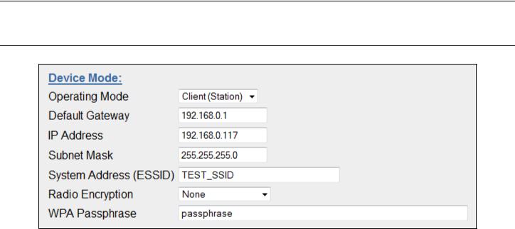
Weidmuller Wireless Ethernet Modem & Device Server WI-MOD-945-E User Manual
3.3 - Quick Start
Figure 15 - Quick Start
The WI-MOD-945-E has a Quick Start Configuration option, which will cover most important parameters that are needed to get an initial connection. This is the first stage of the module configuration. For most applications, no further configuration is required. For more advanced applications, the other parameters can be changed via the normal configuration pages after the Quick Start configuration has been saved.
Select “Quick Start” from the Main Menu and then you need to select the following parameters:
Quick Start Configuration |
|
Operating Mode |
Access Point or Client. Bridge operation is assumed - for Router |
|
selection, go to the Network page after Quick Start |
Default Gateway |
This is the address that the device will use to forward messages to remote |
|
hosts that are not connected to any of the local bridged network (Ethernet |
|
or Wireless) |
IP Address / Subnet Mask |
IP Address and Subnet Mask for your application. |
System Address (ESSID) |
The system address is a text string 1 to 31 characters in length used to |
|
identifies your system |
Radio Encryption |
Radio encryption selection - None, WPA-PSK (TKIP), WPA-PSK (AES) or |
|
WPA2 – refer to Security Menu section if WEP or Enterprise encryption is |
|
required. |
WPA Passphrase |
128bit Encryption keys are internally generated based on the Passphrase |
|
and System Address (ESSID). The Passphrase must be between 8 and |
|
63 characters in length, and must be the same for all WI-MOD-945-E |
|
units in the same system. |
The default settings will be shown. If your system is connecting individual devices which are not connected to an existing Ethernet LAN, then you can use the factory default IP values. If you are connecting to an existing LAN, then you need to change the IP addresses to match your LAN addresses.
After configuring, select “Save to Flash and Reset”.
Radio Data Rate and Channel will be set to Auto, Radio Transmit Power will be set to maximum and any previous configuration of unrelated parameters will not be modified, and will still apply.
Page 29 |
www.weidmuller.com |
Rev 2.136 |

Weidmuller Wireless Ethernet Modem & Device Server WI-MOD-945-E User Manual
3.4 - Network Configuration
Figure 16 - Network
You can view or modify Ethernet network parameters by selecting the “Network” menu. When prompted for username and password, enter “user” as the username, and “user” as the password in the password field (This is the factory default – See section 3.23 - “Module Information Configuration” to change). If you have forgotten the IP address or password, the Factory Default switch may be used to access the existing configuration. Refer to previous section above for this procedure.
The Network Configuration page allows configuration of parameters related to the wired and wireless Ethernet interfaces. In general, IP address selection will be dependent upon the connected wired Ethernet device(s) – before connecting to an existing LAN consult the network administrator.
Default configuration of the module will be Client and Bridge. When in Bridged Mode the modules wired and wireless IP address will be the same, meaning only one IP Address is required. If the Device Mode is changed to Router the page will display two IP addresses, one for Ethernet and one for Wireless. For more information on Bridging Networks see section 3.17 - “Routing Rules“
If the module has been configured for VLAN the page will show Device Mode as VLAN Bridge and the Ethernet IP and netmask will no longer be editable. See Section 3.22 - “VLAN” for more details on VLAN configuration.
A system of WI-MOD-945-E’s must have at least one Access Point configured as a master with one or more Clients. All WI-MOD-945-E’s should be given the same System Address (ESSID) and Radio Encryption settings. For further information and examples on wireless network topologies refer section 1.0 - “Network Topology” above.
The WI-MOD-945-E supports several different radio encryption schemes. If utilising any form of encryption, all modules in the system that communicate with each other will need the same encryption method and encryption keys. The available encryption methods are listed below.
WEP (Wired Equivalent Privacy) encryption is the weakest encryption method, defined by the original IEEE802.11 standard and uses a 40bit or 104bit key with a 24bit initialization vector to give a 64bit and 128bit WEP encryption level. WEP is not considered an effective security scheme, and should only be used if it is necessary to interoperate with other equipment which does not support more modern encryption methods.
WPA (Wi-Fi Protected Access) is a subset of the IEEE802.11i Security Enhancements specification.
Page 30 |
www.weidmuller.com |
Rev 2.136 |
 Loading...