

Weidmuller UR67, UR67-PN-HP-8IOL-12-30M, UR67-PN-HP-8IOL-12-60M Series Manual
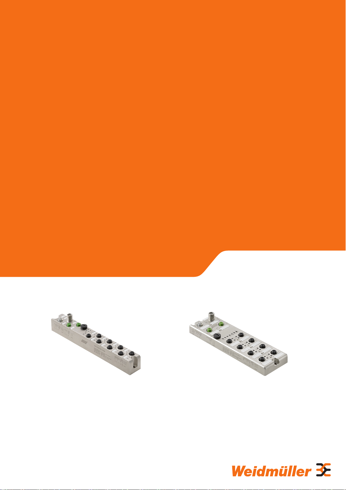
Remote-I/O-System u-remote UR67
I/O-Module IP67 for PROFINET IO-Link
Manual
Letʼs connect.
UR67-PN-HP-8IOL-12-30M 2426250000 UR67-PN-HP-8IOL-12-60M 2426260000

Content
1 About this documentation 3
1.1 Symbols and notes 3
1.2 Complete documentation 3
1.3 Standard data structure 3
2 Safety 4
2.1 General safety notice 4
2.2 Intended use 4
2.3 Legal notice 5
3 System overview 6
3.1 Port characteristics 6
3.2 Fieldbus characteristics 6
3.3 IO-Link functions 7
3.4 Web server 7
3.5 Accessories 7
4 Module descriptions 8
4.1 UR67-PN-HP-8IOL-12-30M 8
4.2 UR67-PN-HP-8IOL-12-60M 9
4.3 Connector pin assignment 10
4.4 Technical data 11
5 Installation and wiring 14
5.1 Preparations for installation 14
5.2 Installing the module and earth connection 14
5.3 Attaching markers 17
5.4 Wiring 17
5.5 Insulation test 17
6 Earthing and shielding 18
6.1 Earthing of shielded cables 18
6.2 Potential ratios 20
6.3 Electromagnetic compatibility (EMC) 20
6.4 Shielding of cables 21
7.5 Conguring IO-Link channels 27
7.6 Parameterising the IO-Link channels 28
7.7 Parameterising the status/control module 30
7.8 Parameterising the IO-Link device 32
7.9 Simple Network Management Protocol (SNMP) 33
7.10 Media Redundancy Protocol (MRP) 33
7.11 Identication & Maintenance functions (I&M) 34
8 Bit allocation 36
8.1 Process data of status/control module, slot1/subslot 1 36
8.2 Process data of IO-Link ports, slot1/subslots2–9 37
9 Diagnostics 38
9.1 System/sensor power supply 38
9.2 Auxiliary/actuator power supply 38
9.3 I/O port sensor power supply outputs 38
9.4 Digital 500mA outputs 38
9.5 Digital 2.0 A outputs 38
9.6 Type-B port aux. power supply 39
9.7 IO-Link C/Q 39
9.8 IO-Link device diagnoses 39
10 Web server 40
10.1 Connecting and starting up the web server 40
10.2 Getting to know and arranging the web server 40
10.3 Module settings and diagnostics 42
10.4 Web server in Force mode 44
10.5 Updating rmware 45
11 Disassembly and disposal 46
11.1 Disassembling the u-remote module 46
11.2 Disposing of the u-remote module 46
12 LED indicators 47
7 Commissioning 23
7.1 Requirements and factory settings 23
7.2 Installing the GSDML le 23
7.3 Connecting the module to the PROFINET network 24
7.4 Assiging device names 26
Manufacturer
Weidmüller Interface GmbH & Co. KG
Klingenbergstraße 16
D-32758 Detmold
T +49 5231 14-0
F +49 5231 14-292083
info@weidmueller.com
www.weidmueller.com
Dokument-No. 2492410000
Revision 00/January 2017
22492410000/00/01.2017 UR67-IO-Link Manual UR67 for PROFINET IO-Link

1 About this documentation
1 About this documentation | Symbols and notes
1.1 Symbols and notes
The safety notices in this documentation are designed according to the severity of the danger.
DANGER
Imminent danger to life!
Notes with the signal word “Danger” warn
you of situations that will result in serious
injury or death if you do not follow the
instructions given in this manual.
WARNING
Possible danger to life!
Notes with the signal word “Warning” warn
you of situations that may result in serious
injury or death if you do not follow the
instructions given in this manual.
CAUTION
Risk of injury!
Notes with the signal word “Caution” warn
you of situations that may result in injury if
you do not follow the instructions given in
this manual.
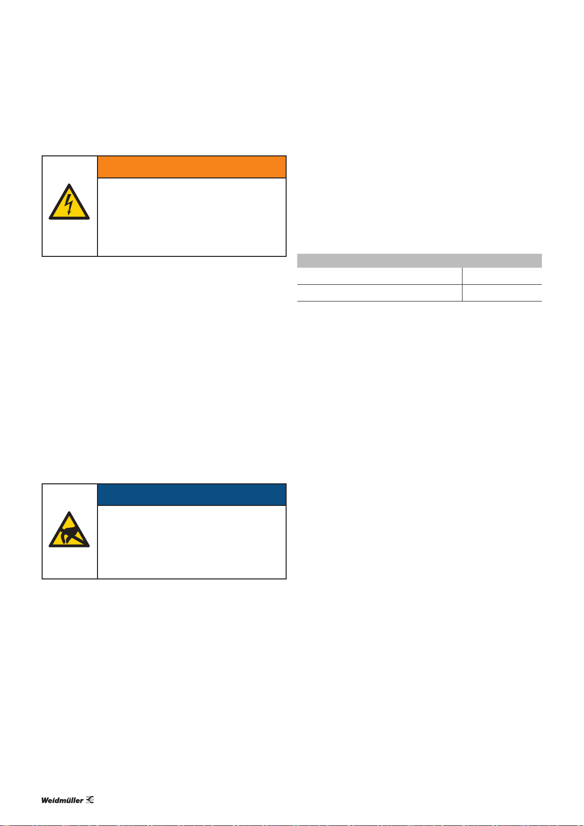
The situation-dependent safety notices may contain the following warning symbols:
Symbol Meaning
Warning against dangerous electrical voltage
Warning against electrostatically charged
components
Warning against automatic startup
Observe the documentation
▶ All instructions can be identified by the black triangles
next to the text.
– Lists are marked with a tick.
21
Female connections with sockets are illustrated
4
1
using empty circles.
3
Male connections with pins are illustrated using
34
lled circles.
2
ATTENTION
Material damage!
Notes with the signal word “Attention” warn you of
hazards that may result in material damage.
Text next to this arrow are notes that are not relevant to safety, but provide important information
about proper and effective work procedures.
1.2 Complete documentation
The documentation is intended for trained electricians who are familiar with national and international laws, provisions and standards.
All documents can also be downloaded from the
Weidmüller website.
1.3 Standard data structure
All information about the structure of data
(e.g.process data and parameters) refers to the
standard data format settings in the module parameters. These are shown in the Motorola format.
32492410000/00/01.2017 UR67-IO-Link Manual UR67 for PROFINET IO-Link

2 Safety
2 Safety | General safety notice
This chapter includes general safety instructions on handling
the UR67 modules. Specic safety instructions for specic
tasks and situations are given at the appropriate places in
the documentation.
All work may only be carried out by trained
electricians who are familiar with the
safety standards that apply to automation
technology.
The documentation must be stored in such a
way that it is accessible to operating staff at all
times.
2.1 General safety notice
When working during ongoing operations, the emergency
stop mechanisms must not be made ineffective.
If faults connected to a u-remote product cannot be rectied,
the product in question must be sent to Weidmüller. Weidmüller assumes no liability if the module is tampered with!
Fusing
The operator must set up the equipment so that it is protected against overloading. The upstream fuse must be designed so that it does not exceed the maximum load current.
The maximum permissible load current can be found in the
technical data. The operator must decide whether additi-
onal surge protection is required according to IEC62305.
Voltages that exceed +/-30V may cause the destruction of
the modules. A power supply with secure isolation must be
used.
Earthing (functional earth FE)
Every UR67-IO-Link module is equipped with an earth connection, with the connection point labelled “XE”. Further
information is available in chapters 5 and 6.
Shielding
Shielded lines are to be connected with shielded plugs in
compliance with the relevant standard (see chapter 6).
2.2 Intended use
All connected devices must comply with the requirements
set out in EN61558-2-4 and EN61558-2-6. Only cables
and accessories that meet the requirements and provisions
regarding safety, electromagnetic compatibility and, if necessary, telecommunications terminal equipment, as well as the
specications, may be installed. Information on the specic
cables and accessories that are permitted to be installed is
provided in this manual or can be requested from Weidmüller.
Electrostatic discharge
u-remote products can be damaged or destroyed by electrostatic discharge. When handling the products, the neces-
sary safety measures against electrostatic discharge (ESD)
according to IEC61340-5-1 and IEC61340-5-2 must be
observed. The packing and unpacking as well as the installation and disassembly of a device may only be carried out by
qualied personnel.
The UR67-IO-Link modules are decentral input and output
devices in a PROFINET network that can be used as an IOLink master. The products are designed for use in industrial
automation and may only be used within the scope of the
stated technical specications. The devices to be connected
must comply with the requirements set out in EN61558-2-4
and EN61558-2-6.
The industrial environment is labelled as such to ensure that
consumers are not directly connected to the public low-voltage network. Additional measures must be taken for use in
the home, and in the business and commercial sectors.
Any intervention in the products hardware or software other
than described in this manual may only be realised by Weidmüller.
Malfunction-free operation is only guaranteed if the housing
is fully assembled. Observance of the documentation is also
part of the intended use.
42492410000/00/01.2017 UR67-IO-Link Manual UR67 for PROFINET IO-Link

2.3 Legal notice
The UR67-series products comply with the EU Directive
2014/30/EU (EMC Directive).
Components of the following free software products are integrated into the modules:
Componente License Link
jQuery MIT
jQuery-custom-
Select
jQuery-i18n MIT
jQuery-overs-
croll
jQuery-ui MIT
JSZip MIT
md5 (as part
of CryptoJS)
snap-svg
underscore MIT
MIT
MIT
MIT
Apache
license 2.0
https://github.com/jquery/jquery/blob/master/
LICENSE.txt
https://github.com/jquery/jquery/blob/master/
LICENSE.txt
https://github.com/jquery/jquery/blob/master/
LICENSE.txt
https://github.com/jquery/jquery/blob/master/
LICENSE.txt
https://github.com/jquery/jquery/blob/master/
LICENSE.txt
https://github.com/Stuk/jszip/blob/master/
LICENSE.markdown
https://code.google.com/archive/p/crypto-js/
wikis/License.wiki
https://github.com/adobe-webplatform/Snap.
svg/blob/master/LICENSE
https://github.com/jashkenas/underscore/blob/
master/LICENSE
2 Safety | Legal notice
52492410000/00/01.2017 UR67-IO-Link Manual UR67 for PROFINET IO-Link

3 System overview
3 System overview | Port characteristics
The UR67-IO-Link modules are IO-Link master modules that
are based on PROFINET. The metal housing (zinc diecast,
completely encapsulated) ensures that they conform to the
IP67 protection class. The UR67-IO-Link modules come in
two designs:
– UR67-PN-HP-8IOL-12-30M: 30-mm width, 8I/O ports
– UR67-PN-HP-8IOL-12-60M: 60-mm width, 8I/O ports
The UR67-IO-Link modules support the IO-Link standard
V1.1. The output current is a maximum of 2A per port. Four
ports have output circuits that are electrically isolated from
the rest of the network and from the sensor electronics.
The modules support a fail-safe function, which can be used
to set how a channel congured as an output is to respond
to an impaired or interrupted PROFINET communication.
All of the module interfaces are equipped with protection
against inverse polarity, short circuits and overloads.
3.1 Port characteristics
All ports are colour-coded and therefore cannot be mixed up:
– PROFINET network (green): D-coded, 4-pole M12 plug-in
connector (IN and OUT). The maximum transmission rate
is 100Mbps.
– I/O ports (black): 8 A-coded, 5-pole M12 plug-in connec-
tors
– Power supply connections (grey): L-coded, 5-pole M12
connector (IN and OUT).
Characteristics of the I/O ports
Each module features 8I/O ports:
– 4type-A ports (IO-Link specification classA) with an addi-
tional, hard-wired digital input at pin2.
– 4type-B ports (IO-Link specification classB) with different
designs depending on the type of module:
– UR67-PN-HP-8IOL-12-30M:
with an electrically isolated auxiliary power supply connected to pins 2 and 5, respectively, and a total current
of 4A
– UR67-PN-HP-8IOL-12-60M:
with an electrically isolated auxiliary power supply connected to pins 2 and 5, respectively, each with a max.
current of 2A (8A total current). The auxiliary power
supply can be congured as a digital output.
LED
Each I/O port is assigned two status LEDs which change co-
lour and the frequency at which they ash according to the
status of the respective port (seechapter 12).
3.2 Fieldbus characteristics
PROFINET product characteristics
The UR67-IO-Link modules support PROFINET IO device IRT
(Isochronous Real-Time). This allows time-critical process
data to be transmitted between the network components
in real time. The modules conform to the PROFINET specication V2.3 as well as to the requirements of Conformance
ClassC (CC-C).
The integrated Ethernet switch with two PROFINET ports allows for the PROFINET network to be set up in a line or ring
topology A highly available network infrastructure can be set
up by also implementing the Media Redundancy Protocol
(MRP).
Supported protocols
The UR67-IO-Link modules use the following protocols:
– DCP: for the automatic allocation of IP addresses
– LLDP: for device detection in the immediate surroundings
(neighbourhood detection)
– SNMP: for monitoring network components and the
communication between the master and the device
I&M functions
Identication and maintenance data (I&M) is information saved in the module.
– The identification data is read-only manufacturer informa-
tion on the module.
– The maintenance data is system-independent information
created during the project planning process.
Modules can be easily identied online using the I&M data.
The following are supported:
– Module-specific I&M functions I&M 0–4 for the network
interfaces (slot0)
– The I&M functions specifically for IO-Link master I&M0
and I&M99 (IO-Link master directory) for the IO-Link
ports (slot1)
Alarm and diagnostic messages
The modules offer expanded PROFINET alarm and diagnostic messages.
Conguration and parameterisation
A GSDML le is needed to congure and parameterise the
module in the engineering tool.
The current GSDML le can be downloaded from
the Weidmüller website.
62492410000/00/01.2017 UR67-IO-Link Manual UR67 for PROFINET IO-Link

3 System overview | IO-Link functions
3.3 IO-Link functions
Parameter storage
This function saves and monitors the IO-Link device and
IO-Link master parameters so that it is easier to exchange in-
dividual components (IO-Link device or IO-Link master). The
function can only be used if it is supported by the IO-Link
device and IO-Link master (IO-Link specication V1.1 and
higher).
Device validation
After being enabled, this function checks whether the iden-
tication data for the connected IO-Link device matches the
values set in the IO-Link master. The transfer of the process
data will only start once all of the checked values match.
Parameterisation of IO-Link devices
The IO-Link devices can be parameterised in PROFINET using
the control unit with the Siemens function components
IO_LINK_CALL (STEP 7) and IO_LINK_DEVICE (TIA Portal).
3.4 Web server
The web server can be used to display the UR67-IO-Link module on a connected PC. This allows you to execute the following functions for test purposes or during commissioning
or service work:
– Query the module status
– Display and change the module parameters
– Access diagnostic information
– Operate the module in Force mode for testing purposes
3.5 Accessories
Protective caps
Protection class IP67 is only realised with a completely connected module. This means that all of the ports not being
used must be sealed off using protective caps.
Size Usage Protective cap Order No.
M12 Sensor connection SAI-SK M12 9456050000
M12 Bus-out and power-out SAI-SK-M12-UNI 2330260000
M12 Bus-in and power-in SAI-SK M12 connector 1781520000
Markers
Module and port markers are available to label equipment. All
of the markers can be printed using the Weidmüller PrintJet
ADVANCED (Order No. 1324380000).
Module Markers Order No.
UR67-PN-HP-8IOL-12-30M MF 5/10 MC NE WS 1954050000
UR67-PN-HP-8IOL-12-60M ESG-M8/20 MC NE WS 1027290000
Conductors and connections
In order to select suitable cables, we recommend referring to
Weidmüller Catalogue8 or the Product Congurator on the
Weidmüller website.
72492410000/00/01.2017 UR67-IO-Link Manual UR67 for PROFINET IO-Link

4 Module descriptions
4 Module descriptions | UR67-PN-HP-8IOL-12-30M
4.1 UR67-PN-HP-8IOL-12-30M
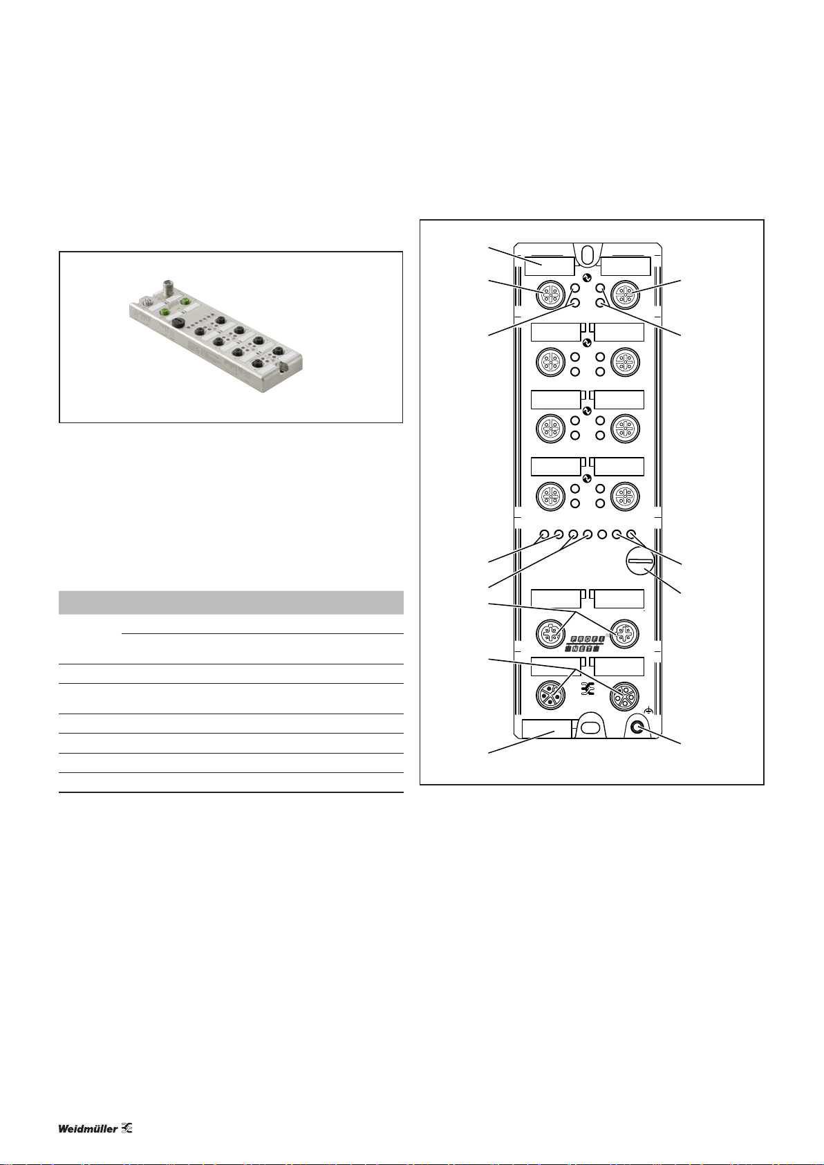
Digital IO-Link module UR67-PN-HP-8IOL-12-30M (Order No. 2426250000)
The digital IO-Link module UR67-PN-HP-8IOL-12-30M is intended for the decentralised control in a PROFINET-network.
The module has 8 slots (M12, 5-pole, A-coded, 4 of typeA
and 4 of typeB) for connecting signal lines as well as connections for the eldbus (M12, 4-pole, D-coded) and for the
power supply (M12, 5-pole, L-coded).
Diagnostic and status LEDs
LED Colour Meaning
1 ... 8 A Green
Yellow Standard I/O mode: status of the digital input or output at
1 ... 8 B
Lnk/Act
White
Green Ethernet connection to another participant available, link
P1, P2
U
U
BF
DIA
Aux
S
Green
Green
Off
Off
LED displays (normal operation), error messages see chapter 12
IO-Link COM mode: IO-Link communication
C/Q (pin 4), cable “on”
Status of the digital input at pin 2, cable “on”
detected
Auxiliary sensor/actuator power supply > 18V
System/sensor power supply > 18V
Connection to the PROFINET controller active
No diagnosis available
1
2
1
A B
A B
5
3
2
3
4
4
5
6
7
X01
IN
IN
8
A B
A B
A B
Link/Act
P2P1
BF
DIA
A B
6
A B
7
A B
8
U
SUAux
BUS
OUT
AUX
OUT
XE
UR67-PN-HP-8IOL-12-30M
1 I/O port typeA (1–4)
2 Status LED port 1
3 Marker port 1
4 Ethernet connection LED (Link/Act)
5 Fieldbus (BF) and diagnostics (DIA) LED
6 Micro-USB port (not to be used by the customer)
7 Fieldbus ports (IN, OUT)
8 Module markers
9 Status LED port 5
10 Marker port 5
11 I/O port typeB (5–8)
12 Status LED power supply
= system/sensor power supply, U
(U
S
= auxiliary sensor/actuator power
Aux
supply)
13 Supply voltage connections (IN, OUT)
14 Earth connection
9
10
11
12
13
14
82492410000/00/01.2017 UR67-IO-Link Manual UR67 for PROFINET IO-Link
4.2 UR67-PN-HP-8IOL-12-60M
4 Module descriptions | UR67-PN-HP-8IOL-12-60M
1
Digital IO-Link module UR67-PN-HP-8IOL-12-60M ( Order No. 2426260000)
The digital IO-Link module UR67-PN-HP-8IOL-12-60M is intended for the decentralised control in a PROFINET-network.
The module has 8 slots (M12, 5-pole, A-coded, 4 of typeA
and 4 of typeB) for connecting signal lines as well as connections for the eldbus (M12, 4-pole, D-coded) and for the
power supply (M12, 5-pole, L-coded).
Diagnostic and status LEDs
LED Colour Meaning
1 ... 8 A Green
Yellow Standard I/O mode: status of the digital input or output at
1 ... 8 B
Lnk/Act
White
Green Ethernet connection to another participant available, link
P1, P2
U
U
BF
DIA
Aux
S
Green
Green
Off
Off
LED displays (normal operation), error messages see chapter 12
IO-Link COM mode: IO-Link communication
C/Q (pin 4), cable “on”
Status of the digital input at pin 2, cable “on”
detected
Auxiliary sensor/actuator power supply > 18V
System/sensor power supply > 18V
Connection to the PROFINET controller active
No diagnosis available
2
3
1
2
3
4 8
A
DIA
B
UR67-PN-HP-8IOL-12-60M
A
DIA
B
A
DIA
B
A
DIA
B
BF DIA
Lnk/Act
P2P1
U
U
Aux
S
4
5
6
IN
BUS
7
IN
AUX
8
UR67-PN-HP-8IOL-12-60M
1 Marker port 1
2 I/O port typeA (1–4)
3 Status LED port 1
4 Ethernet connection LED (Link/Act)
5 Fieldbus (BF) and diagnostics (DIA) LED
6 Fieldbus ports (IN, OUT)
7 Supply voltage connections (IN, OUT)
8 Module markers
9 I/O port typeB (5–8)
10 Status LED port 5
11 Status LED power supply
= system/sensor power supply, U
(U
S
= auxiliary sensor/actuator power
Aux
supply)
12 Micro-USB port (not to be used by the customer)
13 Earth connection
9
5
10
6
7
11
X01
12
OUT
OUT
XE
13
92492410000/00/01.2017 UR67-IO-Link Manual UR67 for PROFINET IO-Link
4 Module descriptions | Connector pin assignment
5
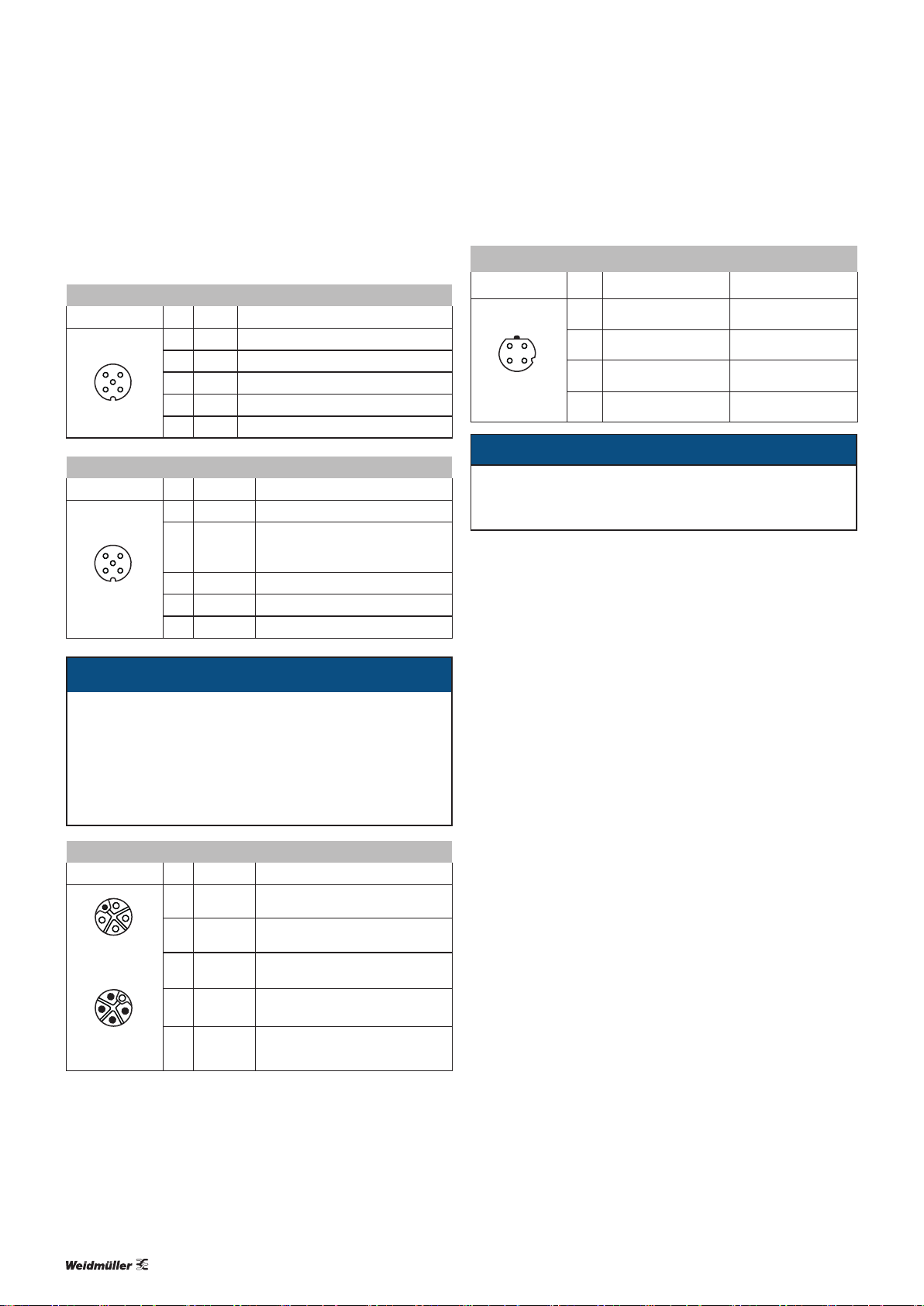
4.3 Connector pin assignment
I/O port typeA
M12, 5-pole Pin Signal Function
1 L+ IO-Link +24 V power supply
3
2
5
M12, 5-pole Pin Signal Function
3
2
2 IN-x Ch. B: Digital input (type 1)
4
3 L– IO-Link GND_U
1
4 C/Q Ch. A: IO-Link data communication
5 n. c. Not connected
I/O port typeB
1 L+ IO-Link +24 V power supply
Ch. B auxiliary power supply
2 U
(+24V)
4
1
Aux
(electrically isolated from the system/sensor
power supply)
3 L– IO-Link GND_US power supply
4 C/Q Ch. A: IO-Link data communication
5 GND_U
Earth/reference potential U
Aux
ATTENTION
power supply
S
PROFINET port
M12, 4-pole, D-coded Pin Signal Function
1 TD+ Transmission data +
21
4
3
2 RD+ Receive data +
3 TD– Transmission data –
4 RD– Receive data –
ATTENTION
The product can be destroyed!
▶ Never place the power supply (24VDC) on the signal
or data lines.
Aux
For the system/sensor power supply and the actuator
power supply, please only use power supplies that con-
form to PELV (Protective Extra Low Voltage) or SELV
(Safety Extra Low Voltage) requirements. Power supplies in accordance with EN61558-2-6 (transformer) or
EN60950-1 (switched-mode power supply) meet these
requirements.
Power supply connection
M12, 5-pole, L-coded Pin Signal Func tion
1
5
2
4
3
OUT
1
5
2
4
3
IN
(+24V) System/sensor power supply
1 U
S
2 GND_U
Earth/reference potential U
Aux
3 GND_USEarth/reference potential U
(+24V)
Auxiliary power supply
(electrically isolated)
4 U
Aux
5 FE (PE) Functional earth
Aux
S
102492410000/00/01.2017 UR67-IO-Link Manual UR67 for PROFINET IO-Link
4 Module descriptions | Technical data
4.4 Technical data
Technical data UR67-PN-HP-8IOL-12-30M (2426250000) UR67-PN-HP-8IOL-12-60M (2426260000)
Bus system
Protocol
Device identification (DeviceID)
Vendor identification (VendorID)
GSDML file
Update cycle
Data transmission rate
Auto-negotiation
Supported Ethernet protocols
SNMPv1 (network diagnosis): Read community: public; Write community: private
Switch functionality
Connection
Electrical isolation of the Ethernet ports/FE
I/O ports 1–8
Number
Connection
Ch.A / C/Q / pin 4 configured as a digital input
Number
Input type
Input wiring
Rated input voltage
Input current at 24VDC
Short-circuit-proof
Status indicator
Diagnosis indicator
Ch.A / C/Q / pin 4 configured as a digital output
Number
Output type
Rated output current per channel
1)
Signal status “1”
Signal status “0”
Signal level of the outputs
Signal status “1”
Signal status “0”
Max. output current
Short-circuit-proof
1) In the case of inductive loads in utilisation category DC13 (in acc. withEN60947-5-1), the outputs can operate with currents of 0.5A and a frequency of 1Hz..
2) Technically possible and approved on the following conditions: looped sensor/system power supply – max. 2.5 A; STL 204 power supply cable (5 x 1.0 mm²);
max. ambient temperature – 40°C; max. current-carrying capacity – 12 A
PROFINET IO device, Conformance Class C (CC-C)
0x0134hex
0x18C6hex
GSDML-Vx.x-WI-UR67-yyyymmdd.xml
1ms
100Mbps full duplex
Supported
Ping, ARP, LLDP, DCP, HTTP, TCP/IP, MRP Client,
integrated, IRT supported
M12, 4-pole, D-coded
2,000VDC
4 typeA and 4 typeB
M12, 5-pole, A-coded
max. 8 congurable
NO contact, P-switching
Type 1 in acc. with IEC 61131-2
24VDC
typically 3mA
yes
Yellow LED
Red LED for each port
max. 8 congurable
NO contact, P-switching
max. 500mA
max. 1mA
min. (US – 1V)
max. 2V
9 A/module
2)
yes
112492410000/00/01.2017 UR67-IO-Link Manual UR67 for PROFINET IO-Link

4 Module descriptions | Technical data
Technical data UR67-PN-HP-8IOL-12-30M (2426250000) UR67-PN-HP-8IOL-12-60M (2426260000)
Overload-proof
Short circuit or overload behaviour
Status indicator
Diagnosis indicator
Switch off, automatic switch on
Yellow LED for each output
yes
Red LED for each port
Ch.A / C/Q / pin 4 as IO-Link channel in COM mode
IO-Link master specification
Transfer rates
Cable lengths for the IO-Link device
Number of IO-Link ports
4.8 kbaud (COM 1), 38.4 kbaud (COM 2) and 230.4 kbaud (COM 3)
v1.1, IEC 61131-9
max. 20m
max. 8 congurable
Ports 1– 4, type B, ch. B / pin 2 as digital inputs
Number
Input type
Input wiring
Rated input voltage
Input current at 24 V DC
Status indicator
Diagnosis indicator
NO contact, P-switching
Type 1 in acc. with IEC 61131-2
4
24VDC
typically 3mA
White LED
Red LED for each port
Ports 5–8, type B, ch. B / pin 2 configured as digital 2-A output
Number
Output type
Rated output current per channel
Signal status “1”
Signal status “0”
Signal level of the outputs
Signal status “1”
Signal status “0”
Max. output current
Short-circuit-proof
Overload-proof
Short circuit or overload behaviour
Filter period in the event of a signal
1)
– 4
– NO contact, P-switching
– 2A
– max. 2A
– max. 1mA
–
– min. (U
– max. 2V
– 16A/module
– yes
– yes
– Switch off, no automatic switch on
– 0–255ms; default 80ms
Aux
– 1V)
2)
change
Status indicator
Diagnosis indicator
– White LED for each output
– Red LED for each port
Module electronics/sensor power supply
Rated voltage U
S
Voltage range
Electronics current consumption
typically 160 mA (± 20% with rated voltage US)
24VDC (SELV/PELV)
24VDC ± 25%
1) In the case of inductive loads in utilisation category DC13 (in acc. withEN60947-5-1), the outputs can operate with currents of 0.5A and a frequency of 1Hz..
2) Technically possible and approved on the following conditions: looped sensor/system power supply – max. 2.5 A; STL 204 power supply cable (5 x 1.0 mm²);
max. ambient temperature – 40°C; max. current-carrying capacity – 12 A
122492410000/00/01.2017 UR67-IO-Link Manual UR67 for PROFINET IO-Link

4 Module descriptions | Technical data
Technical data UR67-PN-HP-8IOL-12-30M (2426250000) UR67-PN-HP-8IOL-12-60M (2426260000)
Sensor voltage
Sensor current consumption (L+/pin 1)
min. (US–1.5 V)
max. 500mA per port (at Tu 30°C)
Short-circuit protection/
overload-protection for the sensor power
yes, for each port
supply
Polarity protection
Status indicator (US)
Connection
M12-Power, 5-pole, L-coded, pin 1
yes
Green LED
Power supply for type-B ports (auxiliary power supply)
Rated voltage U
Aux
Voltage range
Polarity protection
Status indicator (U
Connection
)
Aux
24 V DC (SELV/PELV)
24VDC ± 25%
yes
Green LED
M12-Power, 5-pole, L-coded, pin 4
General data
Protection class
Ambient temperature
Weight
480 g 500 g
IP 67 (when screwed in only)
–20°C to +70°C (–4°F to +158°F)
Dimensions
Housing material
Vibration resistance – vibration
Zinc diecast, nickel matt surface nish
15g/5–500Hz
(DIN EN 60068-2-6 (2008-11))
Vibration resistance – impact
50g/11ms, ±X,Y,Z
(DIN EN 60068-2-27 (2010-02))
Tightening torques
M12 plug-in connector
0.5Nm
1) In the case of inductive loads in utilisation category DC13 (in acc. withEN60947-5-1), the outputs can operate with currents of 0.5A and a frequency of 1Hz..
2) Technically possible and approved on the following conditions: looped sensor/system power supply – max. 2.5 A; STL 204 power supply cable (5 x 1.0 mm²);
max. ambient temperature – 40°C; max. current-carrying capacity – 12 A
132492410000/00/01.2017 UR67-IO-Link Manual UR67 for PROFINET IO-Link
5 Installation and wiring
5 Installation and wiring | Preparations for installation
WARNING
Dangerous contact voltage!
▶ All installation and wiring work must be
carried out with the power supply disconnected.
▶ Make sure that the place of installation
has been disconnected from the power
supply!
5.1 Preparations for installation
Make sure that the permitted environmental conditions for
installation and operation are observed (see Technical data).
Installation position and dimensions
The modules must be installed on a level surface. The instal-
lation dimensions and tightening torques for the xings are
provided in the installation drawings on the following pages.
Unpacking the delivery
▶ Please check the delivery for completeness and transport
damage.
▶ Please report any transport damage immediately to the
respective transport company.
5.2 Installing the module and earth connection
▶ Drill the holes for the fixings (for the drilling dimensions,
see the installation drawings on the following pages).
▶ Affix each module with two screws and a washer (as per
DINEN ISO 7089).
▶ Observe the screw dimension and tightening torques indi-
cated.
Element Torque
M12 plug-in connector 0.5Nm
M12 protective cap 0.5Nm
The modules have an earth connection (“XE”) with an M4
thread for discharging interference currents and for EMC
stability.
▶ Connect the earth connection to the reference earth via a
low-impedance connection.
If the mounting surface is earthed, the connection can be
made directly via the mounting screws.
If the mounting surface is not earthed, use an earthing strap
or a suitable cable!
▶ Connect the earthing strap or the FE cable to the earth
connection (“XE”) using an M4 screw.
ATTENTION
The product can be destroyed by electrostatic discharge!
u-remote products can be destroyed by electrostatic discharge.
▶ Please make sure that personnel and work
equipment are adequately earthed!
▶ Unpack the parts.
▶ Dispose of all packaging in accordance with the local dis-
posal guidelines. The cardboard packaging can be sent
for paper recycling.
142492410000/00/01.2017 UR67-IO-Link Manual UR67 for PROFINET IO-Link

5 Installation and wiring | Installing the module and earth connection
M12
33.4
3
4
female
2
1
5
M12 IO-L Type B
(5-8)
Function Pin
1
+24V
2
+24V
Aux/Out
3
GND
4
C/Q
5
GND Aux
Max. Amblent Temp.: -20° ... +70 °C / -4° ... +158 °F
System Power Supply: 24V +25% / -25%; 200mA
UR67-PN-HP-8IOL-12-30M
Input Power Supply: 24V 200mA
Output Power Supply: 24V 0,5A per Port / PD max.9A
225
1
A B
2
A B
3
A B
4
A B
215.7 ... 217
Link/Act
P2P1
30
15
A B
A B
A B
A B
U
SUAux
M4x 30/35
5
6
7
8
M12
PROFINET
M12
AUX
Installation dimensions UR67-PN-HP-8IOL-12-30M
3
2
BUS
(IN-OUT)
Function Pin
TD +
RD+
TDRD-
FE
POWER
(IN-OUT)
Function Pin
+24V
GND Aux
GND
+24V Aux
FE
43.1
1
4
30
BF
DIA
4
female
1
1
2
3
4
2
female
3
1
2
3
4
5
X01
IN
IN
BUS
OUT
AUX
OUT
XE
M4
XE
M4x 30/35
152492410000/00/01.2017 UR67-IO-Link Manual UR67 for PROFINET IO-Link
 Loading...