

Page 1
Instructions for 0E-RXDST
Request-to-Exit PIR Detector
Application:
The W BOX 0E-RXDST combines a passive-infrared detector with relay
output to allow control of door ingress and egress in request-to-exit
(REX) applications. It is UL Listed as an access control device under
the UL 294 standard. It is for indoor use only. 0E-RXDST is not
designed for use as the primary means of exit for emergency egress.
0E-RXDST can be ceiling or wall mounted over the door and the
detection pattern can be tailored via vertical aim adjustment and/or
masking of the detection pattern.
The relay output consists of two form "C" contacts that can be
adjusted to latch from 0.5 second to 64 seconds. Resettable or
non-resettable can be selected for the latch time. The relay can also
be programmed to fail safe (doors unlocked) or fail secure (doors
locked) mode in the event of a power loss.
0E-RXDST provides advanced features not included on W BOX
model 0E-RXD, including:
• Sequential Triggering to require another input (such as motion
detector or pressure mat) prior to the REX detector motion trigger to
unlock the door (extra security feature to thwart invalid motion triggering)
• Internal sounder (to annunciate door ajar) with volume control
• Door contact monitoring to warn if door is left ajar or door is opened
prior to motion detection.
• Disable function via external device such as access control system
• Selection of normal or high detection sensitivity for the detector’s PIR
• Door Security to prevent tailgating and other unauthorized entry
• Remote input for device such as a card reader to unlock the door.
• Tamper switch
An optional trimplate (W BOX model 0E-TP) is available for easy and
attractive installation using a standard single gang electrical box
oriented horizontally.
Product specications:
• Voltage input: 12VDC or 12VAC; 24VDC or 24VAC
• Current draw: 5-75mA @ 12VDC, depending on setting and status
• NO INTERNAL BATTERY. Budget 38mAh per hour standby
• Relay output: 2 Form C relay contacts rated 2A 30VDC/VAC max.
for DC resistive loads
• Sounder output: Adjustable up to 75dB@1m (dB not UL evaluated)
• Tamper switch rating: 12VDC, 50mA
• Indicator: Green LED for PIR detection
• Relay latch duration: Adjustable from 0.5 second to 64 seconds
• Timer modes: Selectable for resettable (cumulative) or non-resettable
(counting)
• Power loss operation modes: Selectable for fail safe (doors unlocked)
or fail secure (doors locked)
• Mounting locations: Above door(s) controlled on door frame, wall or ceiling
• Mounting height: 7’ to 15’
• Housing: High impact ABS plastic
• Dimensions: 7”W X 1.75”H X 1.88” D (178W X 44H X 48Dmm)
• Operating temperature: -20F to 120F (-29C to 49C); RH: 0-95%
• RFI immunity: 26MHz to 1000 MHz @ 50 V/m (not veried by UL)
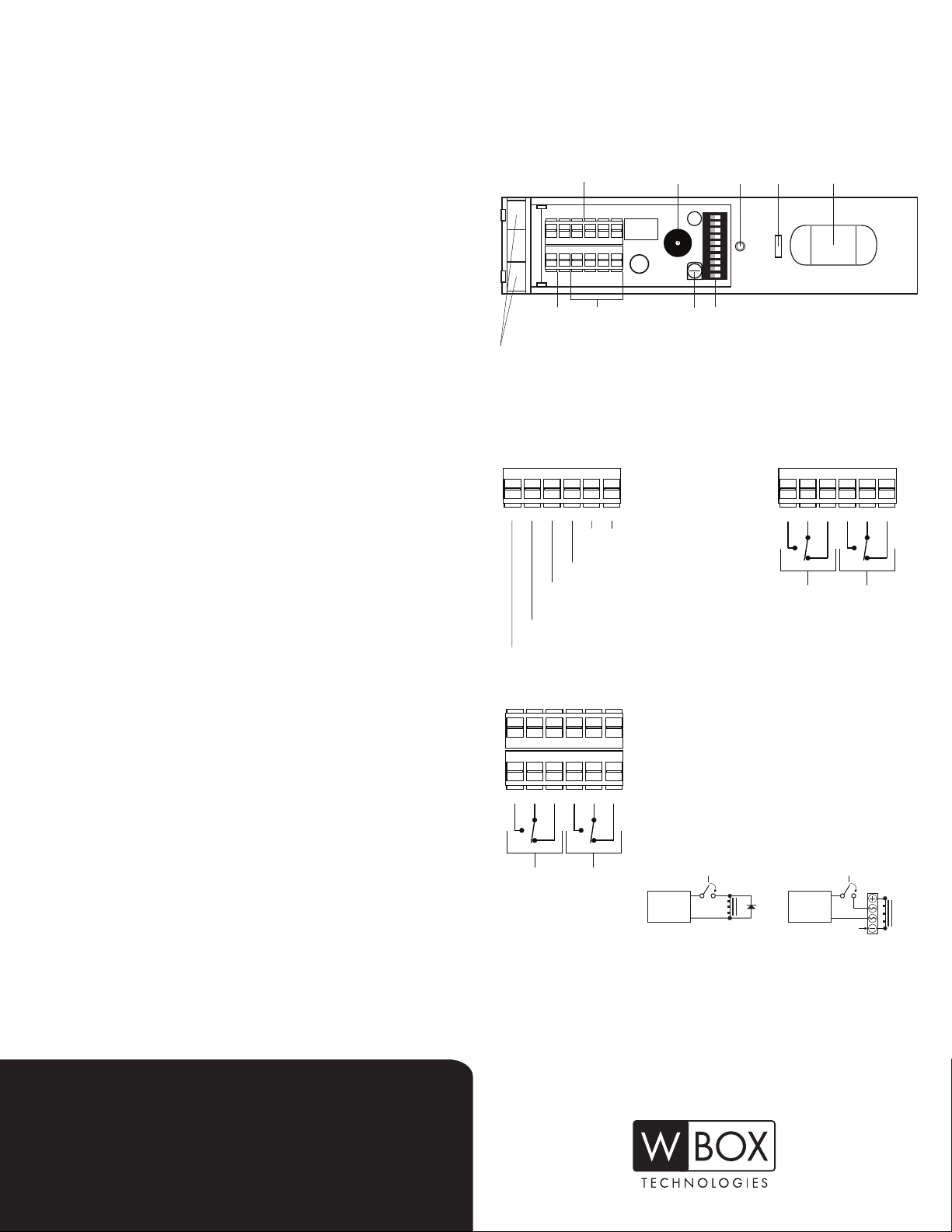
Wiring:
Wiring Terminals
(Relay Contact)
– + R D T T
Terminals
(Power)
Wire Channels
Sounder
NC C NO NC C NO
Advanced
function input
terminals and
tamper contacts (T,T)
Volume
Control
Tamper
Switch
ON DP
1 2 3 4 5 6789 10
DIP Switches Wiring
LED PIR Lens
All wiring connections should be made and veried before any
power, including standby battery if used, is connected to detector.
Connect wires to terminals as follows:
– + R D T T
Tamper switch circuit
(non-polarized)
Door contact monitoring
Input for Sequential Trigger, card
reader or remote control of sounder
+12 OR 24
VDC/VAC
( – ) COM
– + R D T T
Use EMF (voltage) spike-protected relay
NC C NO NC C NO
Non EMF
EMF
(voltage)
spike-
protected
relay
(voltage)
spike-
protected
relay
when connecting inductive loads to the detector
to protect against possible harmful EMF spikes.
Use Non EMF (voltage) spike-protected relay
for non-inductive loads. When connecting an
NC C NO NC C NO
inductive load to the detector that is not spikeprotected (such as a magnetic lock), use either
a 1KV 1A diode or 100V, 4A bridge rectier.
Otherwise relay life may be shortened.
EMF
(voltage)
spike-
protected
relay
Non EMF
(voltage)
spike-
protected
relay
NON SPIKE- PROTECTED RELAY
+
POWER
SUPPLY
–
INDUCTIVE
Most UL1034 listed magnetic locks are already EMF spike-protected
and therefore do NOT require a diode or bridge rectier, and adding
either could cause response delays. Check magnetic lock specications.
LOAD
NON SPIKE- PROTECTED RELAY
+
POWER
SUPPLY
DIODE
–
RECTIFIER
LOAD
INDUCTIVE
REQUEST-TO-EXIT
PIR DETECTOR
Page 2
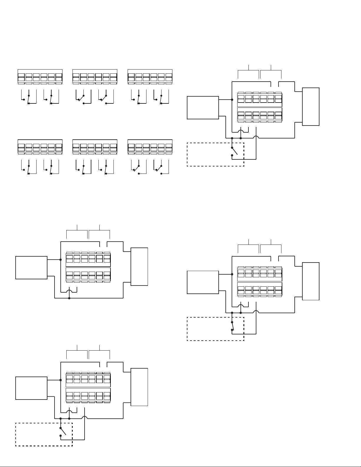
Choose either Fail Safe or Fail Secure operation and wire to
either EMF or Non EMF contacts as follows:
FAIL SAFE
(Switch 3 ON)
Power OFF
FAIL SAFE
(Switch 3 ON)
No Motion
FAIL SAFE
(Switch 3 ON)
Motion Detected
In an installation requiring direct control of the internal sounder
via door contacts or other remote contacts, the wiring is typically
as follows (Fail Safe mode–DIP switch 3 ON, and DIP switch 9 OFF
and 10 ON– Direct Sounder Control mode):
Non EMF EMF
NC C NO NC C NO NC C NO NC C NONC C NO NC C NO
FAIL SECURE
(Switch 3 OFF)
Power OFF
NC C NO NC C NO NC C NO NC C NONC C NO NC C NO
In a basic installation, power is routed through the on-board relay to
a magnetic lock and when motion triggers the PIR detector, the relay is
activated to cut the power to the lock, thereby unlocking the door. The
wiring can be as simple as follows (Fail Safe mode–DIP switch 3 ON):
POWER
SUPPLY
+
–
FAIL SECURE
(Switch 3 OFF)
No Motion
Non EMF EMF
NC C NO NC C NO
– + R D T T
FAIL SECURE
(Switch 3 OFF)
Motion Detected
MAGNETIC
+
LOCK
–
POWER
SUPPLY
NC C NO NC C NO
+
–
– + R D T T
MAGNETIC
+
LOCK
–
ACCESS
CONTROL
CONTACTS
The sounder remains on until the contacts are closed. The relay and
relay latch time are not affected, nor is power removed from the lock.
In an installation requiring higher security, Sequential Triggering
can be implemented to unlock the door (via triggering the PIR motion
detector) only when another device–such as a switch mat, photo
beam or PIR–is activated rst, and the wiring is typically as follows (Fail
Safe mode–DIP switch 3 ON, and DIP switch 9 ON and 10 OFF–
Sequential Triggering mode):
POWER
SUPPLY
Non EMF EMF
+
–
– + R D T T
NC C NO NC C NO
MAGNETIC
+
LOCK
–
In an installation using a card reader for access from outside the
premises, allowing either the card reader or the REX detector to unlock
the door, the wiring is typically as follows (Fail Safe mode–DIP switch 3
ON, and DIP switches 9 and 10 OFF (Card Reader mode):
POWER
SUPPLY
+
–
Non EMF EMF
– + R D T T
NC C NO NC C NO
MAGNETIC
+
LOCK
–
CARD
READER
1ST TRIGGER
DEVICE
Normally Closed contacts
When the rst trigger device is activated, motion detection by
0E-RXDST can unlock the door while the device remains activated
(Terminal R contact is open) and within 10 seconds of when it
deactivates (resets and terminal R contact closes). After the 10
seconds elapse, motion detection by 0E-RXDST cannot unlock the
door unless the rst trigger device is once again activated prior to the
motion detection.
Page 3

One of two options may be selected to utilize Door Contact
Monitoring to warn if door is left ajar or door is opened prior to motion
detection. In Conguration 1, the sounder will activate if the relay
timer is in the last 10 seconds of latch time (latch time must be set to
16 seconds or more via DIP switches 4, 5 and 6–see DIP Switch
Settings) and the door is held or propped open. The sounder will also
activate if the door is opened prior to motion detection. In either
circumstance, the sounder will remain on until either the door closes or
motion is detected. The wiring is typically as follows:
POWER
SUPPLY
Non EMF EMF
+
–
– + R D T T
NC C NO NC C NO
MAGNETIC
+
LOCK
–
DOOR
CONTACTS
Door Contact Monitoring Conguration 2 causes the relay to drop
out after 10 seconds if the detector is triggered by motion but the door
is not opened, or after 2 seconds if the detector is triggered by motion
and the door is opened and then closed. This is designed to prevent
tailgating and other unauthorized entry. The detector can be triggered
by motion or another trigger device such as a switch mat, photo beam
or PIR (similar to first trigger devices for Sequential Triggering) if the R
terminal is used (DIP switch 2 must be ON–Resettable Mode). The
wiring is typically as follows:
POWER
SUPPLY
TRIGGER
DEVICE
Non EMF EMF
+
–
– + R D T T
NC C NO NC C NO
MAGNETIC
+
LOCK
–
DOOR
CONTACTS
Normally Closed contacts
In an installation requiring disabling of 0E-RXDST by another
device such as an intrusion alarm or access control system, the wiring
is typically as follows:
Non EMF EMF
NC C NO NC C NO
+
POWER
SUPPLY
+
–
– + R D T T
DOOR
CONTROLLER
Normally Closed contacts
When the contact connected to Terminal R closes, 0E-RXDST is
disabled following a 10-second delay, resulting in power disconnecting
from the magnetic lock and allowing the door to be opened. This
enables compliance with NFPA Life Safety Code requiring a manual
release device for secured doors that results in interruption of power to
the lock independent of the access control system. Consult with local
AHJ and ensure compliance with all local, regional and national codes.
DIP switch settings:
Selectable operational settings for the detector are programmed via
the ten (10) DIP switches on the circuit board and accessible with the
detector cover removed. Switches are in the on position when the
raised part (shown as white below) is in the upward position toward the
word “ON,” and are in the off position when the raised part is in the
downward position toward the switch number. Shown below are
switches 1-9 in the ON position and switch 10 in the OFF position:
LOCK
–
ON DP
1 2 3 4 5 6789 10
The following operational settings must be selected:
DIP SWITCH 1—LED Enable/LED Disable selection
DIP Switch 3 selects either the LED to light upon detection of motion
or remain off. It is recommended not to select disable prior to walk
testing the detector as it can provide visual feedback of detector
coverage pattern.
LED Enable—switch ON: LED lights upon detection of motion.
LED Disable—switch OFF: LED remains off.
MAGNETIC
Page 4

DIP SWITCH 2—Resettable/Non-resettable timer selection
DIP Switch 2 selects either relay reset at the end of latch time (”Resettable”) or latch time extention upon additional motion (”Non-Resettable”).
Resettable—switch ON: After motion initially activates the relay,
each additional detection of motion motion causes the latch timer to
restart. Only when there is no longer motion and the latch time is
allowed to expire will the relay deactivate. This setting is suitable for
bypassing a 24-hour contact.
Non-resettable—switch OFF: After motion initially activates the
relay, the relay will deactivate when the latch time ends even if there is
additional motion. This setting is suitable for use with access control
systems.
DIP SWITCH 3—Fail Safe/Fail Secure relay mode selection
DIP Switch 3 selects either Fail Safe (doors unlocked) or Fail Secure
(doors locked) operation in the event of a power failure. Setting
selected must comply with all applicable regulations and be veried by
local AHJ (Authority Having Jurisdiction).
Fail Safe—switch ON: In the event of a power failure, the relay
causes the locking mechanism (such as door strike or magnetic lock)
to unlock.
Fail Secure—switch OFF: In the event of a power failure, the relay
causes the locking mechanism (such as door strike or magnetic lock)
to remain locked. Use this setting only with AHJ approval as life safety
can be affected. In addition, ensure there is no interference with
functioning of any panic devices associated with the system 0E-RXDST
is connected to.
DIP SWITCHES 4, 5 and 6—Latch Time selection
DIP Switch 4, 5 and 6 are used in combination to select the duration
of the relay latch time after the relay is ativated by motion detection. Use
the following chart to select a latch time from 0.5 second to 64
seconds:
TIME (seconds) SWITCH 4 SWITCH 5 SWITCH 6
0.5 (default) OFF OFF OFF
1 OFF OFF ON
2 OFF ON OFF
4 OFF ON ON
8 ON OFF OFF
16 ON OFF ON
32 ON ON OFF
64 ON ON ON
DIP SWITCH 7—PIR Sensitivity selection
DIP Switch 7 se;lects either normal or low PIR sensitivity.
Normal Sensitivity—switch ON: Normal sensitivity for REX motion
detection may be higher than the level for security applications because
an unintended trigger does not have the same effect as a false alarm in
an intrusion alarm system, and higher sensitivity improves egress
response.
Reduced Sensitivity—switch OFF: Reduced sensitivity decreases
response but can also decrease unintented triggering.
DIP SWITCHES 8, 9 and 10—Door Security Mode
DIP Switches 8, 9 and 10 are used to select the type of security applied
to the operation of the door. Under the wiring instructions the available
options for door security are shown with respect to the contact relay wiring
that is typically appropriate. These options include the following:
Card Reader Activation—switch 8 does not apply, switch 9 and 10
OFF: Enables input (Terminal R) of a card reader via for access from
outside the premises, allowing either the card reader or the REX detector
to unlock the door.
Internal Sounder Control—switch 8 does not apply, switch 9 OFF
and 10 ON: Enables direct control of the internal sounder via input
(Terminal R) of door contacts or other remote contacts. The sounder
remains on until the contacts are closed. The relay and relay latch time are
not affected, nor is power removed from the lock.
Sequential Triggering—switch 8 does not apply, switch 9 ON and
10 OFF: Enables input (Terminal R) of another device–such as a switch
mat, photo beam or PIR–that must be activated first before motion
detection by 0E-RXDST can unlock the door. 0E-RXDST can unlock the
door while the rst trigger device remains activated (Terminal R contact is
open) and within 10 seconds of when it deactivates (resets and terminal R
contact closes). After the 10 seconds elapse, motion detection by
0E-RXDST cannot unlock the door unless the rst trigger device is once
again activated prior to the motion detection. Sequential Triggering
provides higher security against attempts to trick 0E-RXDST into unlocking
the door by simulating motion that would trigger the PIR (such as slipping
objects under or between doors). This cannot be successful if triggering of
another device is required rst before PIR activation will unlock the door,
assuming the other device is protected from false activation.
Door Contact Monitoring Conguration 1—switch 8 OFF, switch 9
and 10 ON: Enables activation of the internal sounder (via door contacts
connected to Terminal D) if the relay timer is in the last 10 seconds of latch
time (latch time must be set to 16 seconds or more via DIP switches 4, 5
and 6–see DIP Switch Settings) and the door is held or propped open.
The sounder will also activate if the door is opened prior to motion
detection. In either circumstance, the sounder will remain on until either
the door closes or motion is detected.
Door Contact Monitoring Conguration 2—switch 8, 9 and 10 ON:
Enables triggering the internal relay to drop out (via input of door contacts
connected to Terminal D) after 10 seconds if the detector is triggered by
motion but the door is not opened, or after 2 seconds if the detector is
triggered by motion and the door is opened and then closed. This is
designed to prevent tailgating and other unauthorized entry. The detector
can be triggered by motion or another trigger device such as a switch mat,
photo beam or PIR (similar to first trigger devices for Sequential Triggering)
if Terminal R is used (DIP switch 2 must be ON–Resettable Mode).
REX Detector Disable—switch 8 does not apply, switch 9 ON and
10 OFF: Enables (via contacts connected to Terminal R) disabling of
0E-RXDST by another device such as an intrusion alarm or access control
system. When the contact connected to Terminal R closes, 0E-RXDST is
disabled following a 10-second delay, resulting in power disconnecting
from the magnetic lock and allowing the door to be opened. This enables
compliance with NFPA Life Safety Code requiring a manual release device
for secured doors that results in interruption of power to the lock independent of the access control system. Consult with local AHJ and ensure
compliance with all local, regional and national codes.
Page 5

Installation:
Remove the cover of the detector by inserting a at head screwdriver into
the slot visible (at the extreme end opposite the end with the PIR lens) on
the back of the detector and prying it off. Follow instructions for wiring and
DIP switch settings.
Cover
Detection Module
Remove detection
module from base
by rotating clockwise
Base
with right hand as you
view PIR lens side on
your right, and lifting.
Route wires through the wiring entrances on the left side of the detector.
For surface wiring, carefully cut out the breakaway notch provided on the
cover at the same end as the wire entrances appear on the base.
The detector can be mounted from 7 ft to 15 ft. (2.1m to 4.6m) above the
oor. Mounting height affects the detection pattern, generally expanding it
as the height increases.
Mount the base to the mounting surface using mounting screws supplied.
The word “DOOR” on the base must be right side up (and arrows
pointing down toward door) for correct mounting.
Re-insert the detection module into the base (turning counter-clockwise,
opposite of removal shown above). Aim the detector for coverage desired.
Tighten detector module lock screw to prevent movement of the detector
module and disruption of coverage pattern due to vibration, etc.
NC C NO NC C NO
– + R D T T
ON DP
1 2 3 4 5 6789 10
After aiming detector
for desired coverage,
tighten lock screw to
secure detector
positioning.
Detection coverage pattern:
The ideal installation of 0E-RXDST provides responsiveness to the
motion of persons attempting to exit while minimizing unintended
triggering of the detector. Persons moving at a normal pace toward the
door(s) to exit should be able to push the door open without waiting for
the door to unlock. Persons in areas not close to the door and not
moving toward the door to exit should generally not cause the door to
unlock by triggering the detector. In addition to advanced feature
settings and congurations such as PIR Sensitivity and Door Security
Mode, achieving the proper balance of ensuring responsiveness while
minimizing unintended triggering is mostly a function of the following
factors affecting the coverage pattern:
• Choice of wall (including door frame) or ceiling mount
• Mounting height
• Aiming of the detector (vertical only)
• Masking of the PIR lens (see “Installation” on previous page)
In general, the further from the oor the detector is located, the larger
the detection pattern becomes. The higher the detector is aimed, the
further the pattern extends (when wall mounted) though detection
range is limited to about 20 feet (about 6 meters) maximum. Aiming the
detector lower to bring the coverage pattern closer to the door can
help eliminate triggering from persons moving in the vicinity of the door
without intending to exit. When selecting Non-resettable latch time (DIP
switch 2 OFF), adjust latch time (DIP switches 4,5 and 6) to allow persons
intending to exit to reach the door in time after triggering the detector.
The Fresnel lens of the PIR detector is segmented to provide six (6)
dual detection zones. The body heat (IR energy) of a person moving
through a zone triggers the detector. When wall mounted at a height of 7’
with the detector aimed downward by 14° 0E-RXDST, produces approximately the follwing coverage pattern on the oor as seen from above:
Top view of coverage pattern on the oor
at 7’ wall mount height with -14 aim
4.5 3.0 1.5 1.5 3.0 4.5
0
5
DETECTOR
Aimed -14°
0
1.5
Meters
Meters
To mask the PIR detection pattern, insert masking wedges using small
holes at top and bottom of PIR lens on outside surface of detector.
Masking can reduce unintended activation by persons not intending egress.
Masking wedge
inserted to block part
of detection pattern
After verifying detection coverage pattern by walk test, make sure all wiring
and DIP switch settings are correct and that detection module aim is
locked. Replace cover and press rmly to snap in place.
Optional trim plate:
0E-RXDST is not tall enough to cover a single gang box. For a neat,
attractive installation, mount the detector using the optional trimplate (0E-TP):
Wire port
Screw holes for
mounting to single
gang electical box
Route wires through trim plate, into channels on back of detector base
and through wiring channels on left side. When mounting detector base as
described above, after inserting screws through holes in detector base,
pass them through trim plate holes and into mounting holes on installed
single gang box. Tighten screws.
Feet
10
15
15 10 5 0 5 10 15
3
4.5
Feet
When wall mounted at a height of 15’ with the detector aimed upward
by 14° 0E-RXDST, produces approximately the following expanded
coverage pattern on the oor as seen from above:
Top view of coverage pattern on the oor
at 15’ wall mount height with +14 aim
4.5 3.0 1.5 1.5 3.0 4.5
0
5
Feet
10
15
15 10 5 0 5 10 15
DETECTOR
Aimed +14°
Feet
0
1.5
3
4.5
Meters
Meters
Page 6

Aiming the detector lower brings coverage closer to the door, possibly
reducing unintended triggering of the detector. When wall mounted at a
height of 7’ with the detector aimed downward by 14°, 0E-RXDST
produces approximately the following coverage pattern on the oor as
seen from above:
Top view of coverage pattern on the oor
at 7’ wall mount height with -14 aim
3.0 1.5 1.5 3.0
0
Feet
5
10 5 0 5 10
DETECTOR
Aimed -14°
Feet
0
Meters
1.5
Meters
When wall mounted at a height of 15’ with the detector aimed
downward by 14°, 0E-RXDST, produces approximately the following
expanded coverage pattern on the oor as seen from above:
Top view of coverage pattern on the oor
at 15’ wall mount height with -14 aim
3.0 1.5 1.5 3.0
0
Feet
5
10 5 0 5 10
DETECTOR
Aimed -14°
Feet
0
Meters
1.5
Meters
Viewed from the side, the coverage range is approximately as follows:
Side view of coverage range
with -14 aim
0 1.5 3 4.5 Meters
0
7’
5
15’
Feet
10
15
0 5 10 15
Feet
0
1.5
3
4.5
Meters
Side view of coverage range
with +14 aim
0 1.5 3 4.5 Meters
0
7’
5
15’
Feet
10
15
0 5 10 15
Feet
0
1.5
3
4.5
Meters
To provide responsive egress for double doors, mount one 0E-RXDST above
the center of each door and wire the outputs so that detection of motion
by either detector will unlock the doors. In most cases, masking the inside
zones on both detectors will not affect responsiveness yet may reduce the
possibility of triggering from insertion of an object between the two doors.
Installation testing:
All wiring connections should be made and veried before any power is
connected to the detector. All power, including standby battery if used,
should be disconnected.
Do not replace detector cover before the following have been completed:
• All wiring connections have been made and veried
• Detector has been properly mounted
• A walk test has been conducted to conrm coverage and proper functioning
of the system
Apply power to the unit after determining all wiring connections have been
properly made and that no hazards exist. The detector’s green LED will initially
ash on and off unless it has been disabled (DIP switch 1 set to OFF position).
The LED should be enabled (DIP switch 1 set to ON position) to conduct a
proper walk test and can be disabled afterward if required prior to replacing
detector cover.
Allow the detector to stabilize for ve (5) minutes. Conduct a walk test by
approaching the door from all angles that persons can normally be expected to
approach from and verify responsiveness. Adjust the detector aim up or down
as necessary to optimize the detection pattern. Also verify that trafc not
intending to exit does not typically trigger the detector. If necessary, adust the
detector aim. Mask the PIR lens if necessary.
Be sure to tighten the lock screw for the detector aim after detection coverage
has been nalized.
Ensure that latch duration allows enough time to reach the door after detection
and adjust if necessary.
Verify Fail-Safe or Fail-Secure operation by temporarily disconnecting power to
the unit and determining that door is unlocked (Fail-Safe) or locked (Fail-Secure).
Reset DIP switch 3 if necessary and repeat test. Setting selected must comply
with all applicable regulations and be veried by local AHJ (Authority Having
Jurisdiction).
After conrming the detector is operating as required (including leaving LED
enabled or disabling it following nal walk test), replace the cover and perform
one nal walk test to ensure proper operation.
The detector should be tested at least once a year to ensure proper operation
of all functions.
Important Note:
0E-RXDST is designed for installation by properly trained, experienced and
qualied technicians only. It should
be installed in compliance with all applicable
local, regional and national electrical and safety codes.
Performance Level Current Ratings
0E-RXDST meets the following The following are the maximum
performance levels for Access current ratings for each input
Control (UL294 6th Edition): voltage:
Feature Level Input Voltage Max. Current
Destructive Attack I 12VDC 16mA
Line Security I 12VAC 52mA
Endurance IV 24VDC 20mA
Standby Power I 24VAC 64mA
Install in accordance with National Electric Code (NEC 70) and the
applicable National Fire Protection Association (NFPA) Installation
Standards, local codes and the local Authority Having Jurisdiction (AHJ).
All Circuits Class 2. Units shall be connected to a UL 294 or 603 power
limited class 2 output power supply.
The gap between double doors without a center post may allow intruders
to trigger the motion detector by inserting a hot or cold object into the
detection pattern. An alternative mounting option should be chosen to
avoid this possibility, such as ceiling mounting away from the door.
ACCESS CONTROL
UL 294 LISTED
ACCESS CONTROL SYSTEM UNITS
Edition 6
LISTED
www.wboxtech.com Questions: Info@wboxtech.com
Doc. N0.: 0E-RXDST II Rev. 001 12-03-18
 Loading...