

Page 1
IN-CEILING
8” SUBWOOFER
0E-ICS8
Page 2

2
Introduction
Congratulations and thank you for purchasing W Box Technologies
0E-ICS8 In-Ceiling Subwoofer with Sonic Vortex.
Our patented Sonic Vortex Technology is based on Ported Transmission
Line design and incorporates a compact, integrated enclosure. Most
In-ceiling speakers do not utilize a back box, even fewer have an
enclosure, and only a Sonic Vortex speaker has an Integrated
Transmission Line Ported Enclosure. Without something behind the
speaker driver the music not only plays into the room, but also bleeds
into adjoining rooms such as the attic or an occupied room. The bleed
negatively affects performance, and sound consistency.
The Sonic Vortex enclosure directs all of the sound from the speaker
driver into the room it is intend to be in, so you get to enjoy your
speakers without disturbing the rest of the house. Great bass response,
stereo image, and big sound that you can’t get with any other in-ceiling
speaker.
The 0E-ICS8 subwoofer installs with ease using the ‘dog’ mounting
system and magnetic bezelless grills for fast, clean installations.
Please follow the instructions in this manual to assure proper
installation and to achieve the full performance and satisfaction you
would expect from W Box Technologies.
TECHNOLOGY
POWERED BY:
Page 3

3
Speaker Placement
When installing in-ceiling speakers or subs, (or in-ceiling anything for
that matter) it is always a good idea to nd out what is in the ceiling
before cutting holes. Be aware of the location of plumbing, electrical
and structural elements that may affect speaker placement.
Stereo
It is also a good idea to locate stereo speakers so they are centered to
the main listening position in which the user/s will normally be located.
Whenever possible, try to position the left and right speakers at the
same distance from each other as they are from the main listening
position.
Subwoofer
Subwoofers are omni-directional so placement of in-ceiling subs is
somewhat less critical, but placement can be affected (good and bad)
by corners and walls, so try to nd a location that will be somewhat
unaffected by placement.
Surround
Locate surround speakers according to the recommendations in the
surround processor’s owner’s manual.
Page 4

4
Installation
SPEAKER WIRE
Pull one run of 16AWG stranded speaker wire from the amplier
location to each speaker location. If in pre-wire, while the walls are
open and it’s easy, pull extra wire to any location that may be desirable
to add speakers at a later date. Leave extra length of wire on each end
to allow making connections and installing/removing speakers.
Use the chart below to determine the proper gauge of wire, based upon
wire length from the amp to the speakers. If using volume controls,
include the total length from the amp to the volume control and then to
the speakers.
SPEAKER WIRE GAUGE TABLE
SPEAKER WIRE LENGTH SPEAKER WIRE GAUGE
150’ (46m) 16AWG
400’ (122m) 14AWG
NEW CONSTRUCTION
W Box Technologies speaker installation can be simplied by using a W
Box Technologies new construction 0E-EZBRACKET, (sold separately).
This is installed prior to drywall installation and allows for precise
speaker placement and simplies the nal installation of the speaker.
EXISTING CONSTRUCTION
Speaker wire must be run from the equipment or volume control
location to each potential speaker location.
• Choose a location for each speaker that is free of obstructions
created by joists, HVAC duct-work, electrical wire runs, plumbing
or anything else that might not allow for the depth of the speaker or
create interference or noise.
Page 5
5
Installation
• Once you have determined your locations, use a pencil to mark the
hole to cut out for the speaker using the supplied template. Don’t
forget to allow for the size of the speaker bezel if you are installing
the speaker near a sidewall or other item that could become an
obstacle.
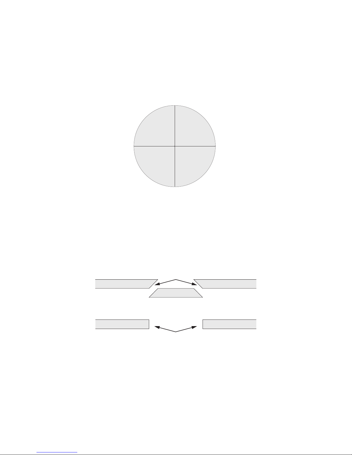
• If you are unsure of potential obstacles, carefully cut your holes
using an angle to the inside of the cutout area. This will allow you
to “plug” the hole easily if needed. If the area is clear and is a good
location for the speaker, go ahead and cut the edges of the opening
at 90 degrees to accommodate the speaker diameter.
Cut hole at an angle in case patching is necessary
Save cutout for patching if necessary
Cut edge at 90°if area is clear of obstructions
Page 6
6
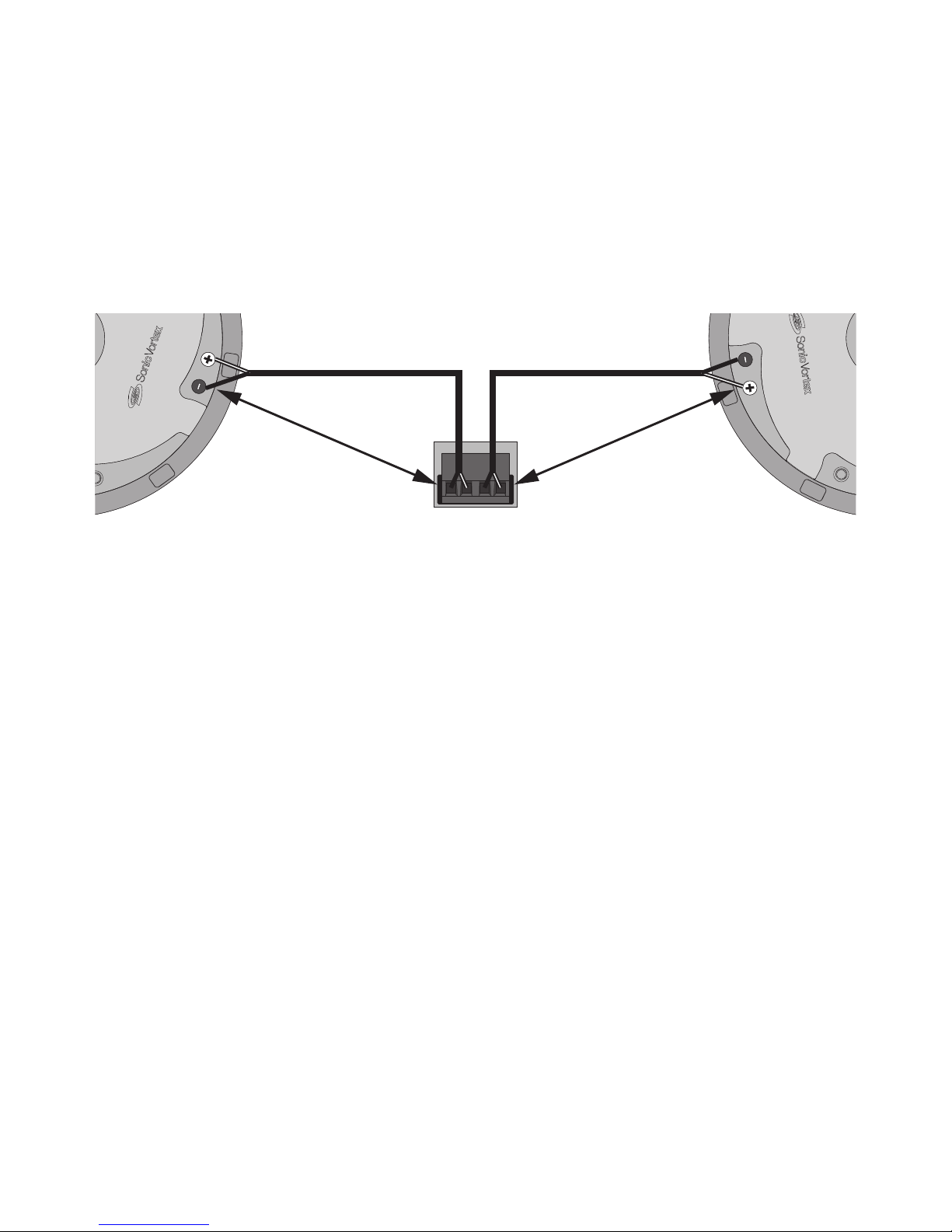
• Strip the insulation on each conductor approximately 1/2” (12.7mm)
and insert to the speaker terminals. Ensure that there are no stray
strands of wire protruding from the connectors that can cause
shorts. Observe proper polarity (+ to + and – to – for each speaker
and at the amplier) and that surround channels are properly
positioned and connected, if used.
L-
L+ R- R+
Amplifier Speaker Terminal
16AWG (min)
Stranded Speaker Wire
+ to +
- to -
+ to +
- to -
16AWG (min)
Stranded Speaker Wire
Installation
Page 7
7
Installation
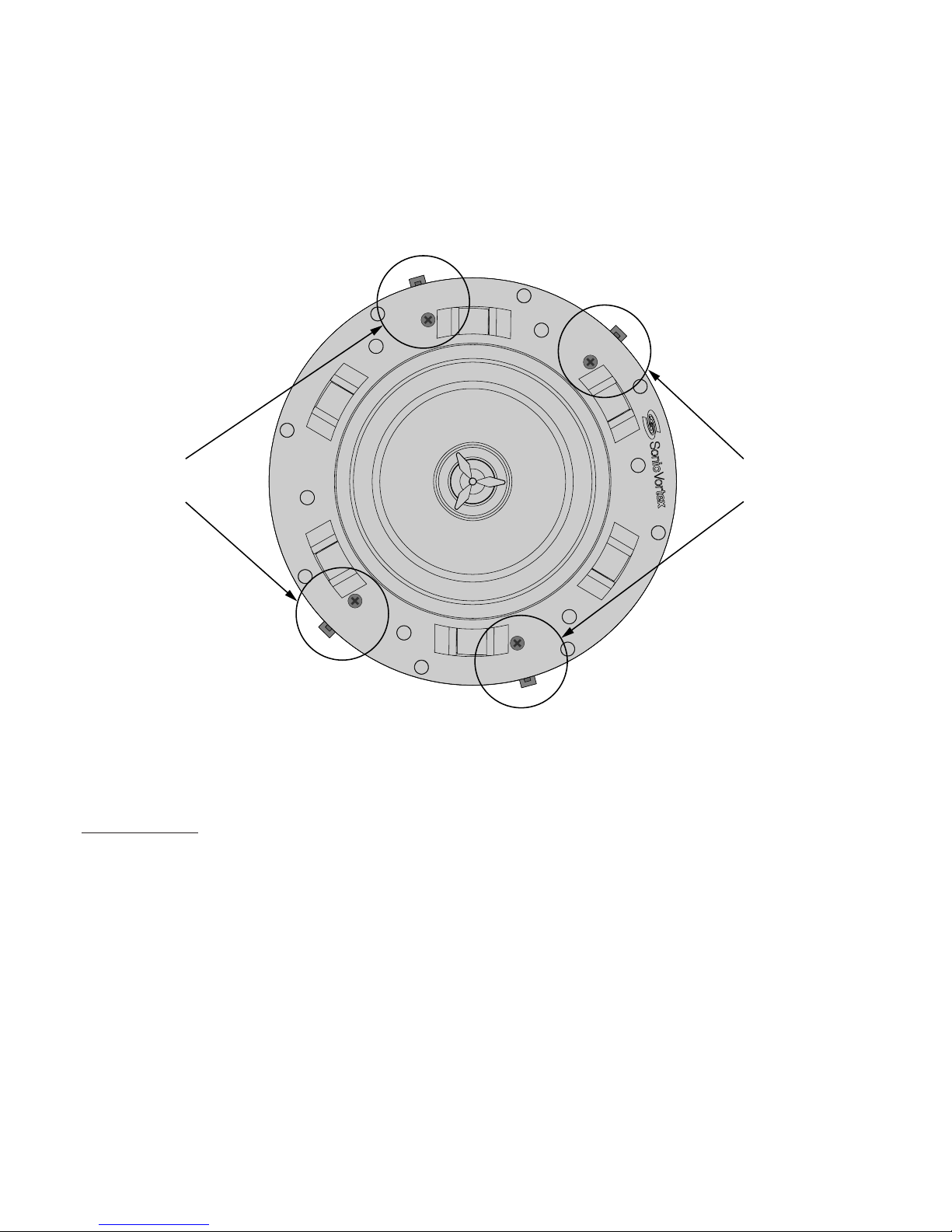
• With the ‘dogs’ ush to the side of the speaker, insert the speaker
into the ceiling and tighten each of the four screws for the
speakers’ dogs, enough to clamp the speaker to the drywall. Do not
overtighten.
Turn screws to extend dogs
as shown
Turn screws to extend dogs
as shown
• Attach the grill to the subwoofer. The grill attaches with magnets so
it will just snap into place.
PAINTING
The grill may be painted, but go as light as possible to not to clog the
ne holes with paint. Only paint grills when they have been removed
from the speakers and be sure to remove the cloth on the backside of
the grill before painting. If the cloth is not removed for painting, it will
absorb the paint and clog the grill, signicantly affecting the sound...and
not in a good way.
Page 8

8
Troubleshooting
W Box Technologies speakers are designed to function trouble-free.
Most problems that occur are due to simple issues. If you have trouble,
please check the list of simple xes below.
SPEAKER TROUBLESHOOTING
PROBLEM SOLUTION
NO SOUND Verify that there is audio from the
source selected. Select another
source if necessary.
Ensure that the amplier is turned
on and connected properly.
Check any connections at oth-
er devices, such as a volume
control. Temporarily bypass the
control if needed.
Check wire connections at each
speaker not producing sound for
good contact to bare wire, not
wire insulation.
Page 9

9
Specications
Frequency Response: .............................................................. 36-400Hz
Frequency/Crossover Setting: ........................................80Hz and Below
RMS Power: ............................................................................ 100 Watts
Max Power: ..............................................................................200 Watts
Speaker Driver: ........................................................ 8” Silver IMPP Cone
Impedance: ................................................................................... 8 Ohm
Grill Diameter: .................................................................................. 11. 2”
Mounting Diameter: ......................................................................... 10.3”
Mounting Depth: ................................................................................8.6”
Mounting Style: .............................................................. 4 Locking ‘Dogs’
Grill: ................................................................... Bezelless Magnetic Grill
Page 10

10
Limited Warranty
1. Limited Warranty
a. General
Subject to the terms and conditions of this Limited Warranty, from the date of sale
through the period of time for product categories specied in Section 1(b), ADI
warrants its W Box Technologies products to be free from defects in materials and
workmanship under normal use and service, normal wear and tear excepted. Except
as required by law, this Limited Warranty is only made to Buyer and may not be
transferred to any third party.
ADI shall have no obligation under this Limited Warranty or otherwise if:
(i) The product is improperly installed, applied or maintained;
(ii) The product is installed outside of stated operating parameters, altered, or
improperly services or repaired;
(iii) Damage is caused by outside natural occurrences, such as lightning, power
surges, re, oods, acts of nature, or the like.
(iv) Defects resulting from unauthorized modication, misuse, vandalism, or other
causes
unrelated to defective materials or workmanship, or failures related to batteries of
any type used in connection with the products sold hereunder.
ADI only warrants those products branded as W Box Technologies products and sold
by ADI. Any other products branded by third parties are warranted by the third party
manufacturer for a period as dened by the third party manufacturer, and ADI assigns
to Buyer those warranties and only those warranties extended by such third party
manufacturers or vendors for non-ADI branded products. ADI does not itself warrant
any non-ADI branded product and sells only on an as is basis in accordance with
ADI’s terms and conditions of sale.
Page 11

11
b. Specic Warranties for product categories are as follows:
Product Categories Warranty Period
Soundbars 12 months
Televisions 12 Months
Intrusion Wireless Communication
Accessories
12 Months
Analog Cameras 24 months
CCTV Power Supplies 24 months
In-Ceiling Speakers 24 months
Ampliers 24 months
Magnetic Locks 24 Months
Request to Exit Devices 24 Months
Surge Protection 24 months
UPS (uninterruptible power supplies) 24 months
Volume Controls 24 months
Intrusion Audio Devices 30 months
Monitors 30 months
Video Baluns 30 months
DVR’s, NVR’s 60 Months
IP Cameras 60 Months
Racks 60 months
TV Mounts 60 months
PIR’s 84 months
Analog Cables Limited Lifetime
B Connectors Limited Lifetime
Bus Terminals Limited Lifetime
Extension Cords Limited Lifetime
HDMI Cables Limited Lifetime
Jacks, Cords and Intrusion
Communication Accessories
Limited Lifetime
Patch Cables Limited Lifetime
Raceway Conduit Limited Lifetime
Wire Ties Limited Lifetime
Magnetic Contacts Limited Lifetime
Limited Warranty
Page 12

12
2. EXCLUSION OF WARRANTIES, LIMITATION OF LIABILITY
THERE ARE NO WARRANTIES OR CONDITIONS, W Box Technologies OR
IMPLIED, OF MERCHANTABILITY, OR FITNESS FOR A PARTICULAR PURPOSE
OR OTHERWISE, WHICH EXTEND BEYOND THE DESCRIPTION ON THE FACE
HEREOF. TO THE FULLEST EXTENT PERMITTED BY LAW, IN NO CASE SHALL
ADI BE LIABLE TO ANYONE FOR ANY (I) CONSEQUENTIAL, INCIDENTAL,
INDIRECT, SPECIAL, OR PUNITIVE DAMAGES ARISING OUT OF OR RELATING
IN ANY WAY TO THE PRODUCT AND, OR FOR BREACH OF THIS OR ANY
OTHER WARRANTY OR CONDITION, W Box Technologies OR IMPLIED, OR
UPON ANY OTHER BASIS OF LIABILITY WHATSOEVER, EVEN IF THE LOSS
OR DAMAGE IS CAUSED BY ADI’S OWN NEGLIGENCE OR FAULT AND EVEN
IF ADI HAS BEEN ADVISED OF THE POSSIBILITY OF SUCH LOSSES OR
DAMAGES. Any product description (whether in writing or made orally by ADI
or ADI’s agents), specications, samples, models, bulletin, drawings, diagrams,
engineering sheets, or similar materials used in connection with the Buyer’s order
are for the sole purpose of identifying ADI’s products and shall not be construed
as a W Box Technologies warranty or condition. Any suggestions by ADI or ADI’s
agents regarding use, applications or suitability of the products shall not be
construed as a W Box Technologies warranty or condition unless conrmed to be
such in writing by ADI. ADI does not represent that the products it sells may not be
compromised or circumvented; that the products will prevent any personal injury or
property loss by burglary, robbery, re or otherwise, or that the products will in all
cases provide adequate warning or protection. Buyer understands and will cause
its customer to understand that a properly installed and maintained product is not
insurance or guarantee that such will not cause or lead to personal injury or property
loss. CONSEQUENTLY ADI SHALL HAVE NO LIABILITY FOR ANY PERSONAL
INJURY, PROPERTY DAMAGE OR OTHER LOSS BASED ON ANY CLAIM AT ALL
INCLUDING A CLAIM THAT THE PRODUCT FAILED TO GIVE WARNING. However,
if ADI is held liable whether directly or indirectly for any loss or damage with respect
to the products it sells, regardless of cause or origin, its maximum liability shall not in
any case exceed the purchase price of the product, which shall be xed as liquidated
damages and not as a penalty and shall be the complete and exclusive remedy
against ADI.
3. Limitation on Liability to Buyer’s Customers.
Buyer agrees to limit liability to its customers to the fullest extent permitted by
law. Buyer acknowledges that ADI shall only be deemed to give consumers of its
products such statutory warranties as may be required by law and at no time shall
Buyer represent to its customers and/or users of ADI products that ADI provides any
additional warranties. By accepting the products, to the fullest extent permitted by law,
Buyer assumes all liability for, and agrees to indemnity and hold ADI harmless against
Limited Warranty
Page 13

13
and defend ADI from, any and all suits, claims, demands, causes of action and
judgments relating to damages, whether for personal injury or to personal property,
suffered by any person, rm, corporation or business association, including but not
limited to, Buyer’s customers and/or users of the products because of any failure of
the products to detect and/or warn of the danger for which the goods were designed
or any other failure of the products whether or not such damages are caused or
contributed to by the sold or joint concurring negligence or fault of ADI.
4. Returns
Subject to the terms and conditions listed below, during the applicable warranty
period, ADI will replace Product or provide a credit at purchase at its sole option free
of charge any defective products returned prepaid. Any obligations of ADI to replace
Limited Lifetime warranty products pursuant to this warranty which result from defect
are limited to the availability of replacement product. ADI reserves the right to replace
any such products with the then currently available products, or provide a credit in its
sole discretion. In the event Buyer has a problem with any ADI product, please call
your local ADI branch for return instructions:
For US call 1-800-233-6261
For Canada call 877-234-7378
For Puerto Rico call 787-793-8830
Be sure to have the model number and the nature of the problem available. In the
event of replacement, the return product will be credited to Buyer’s account and a new
invoice issued for the replacement item. ADI reserves the right to issue a credit only in
lieu of replacement.
If any W Box Technologies product is found to be in good working order or such
product’s inability to function properly is a result of user damage or abuse, the product
will be returned to Buyer in the same condition as received and Buyer shall be
responsible for any return freight changes.
5. Governing Law
The laws of State of New York apply to this Limited Warranty.
6. Miscellaneous
Where any term of this Limited Warranty is prohibited by such laws, it shall be null and
void, but the remainder of the Limited Warranty shall remain in full force and effect.
Limited Warranty
Page 14

14
Introduction
Bravo et merci d’avoir acheté le caisson de basses pour plafond
0E-ICS8 W Box Technologies avec Sonic Vortex.
Notre technologie Sonic Vortex brevetée se base sur une conception
d’enceinte à ligne de transmission portée, mais aussi intégrée et
compacte. La plupart des haut-parleurs pour plafond ne comportent
pas de boîte d’encastrement. Il est encore plus rare qu’ils soient équipés
d’une enceinte, et seul le haut-parleur Sonic Vortex dispose d’une
enceinte portée à ligne de transmission intégrée. S’il n’y a rien derrière
le haut-parleur élémentaire, la musique sera non seulement diffusée dans
la pièce où les haut-parleurs sont installés, mais aussi dans les pièces
voisines telles que le grenier ou une chambre occupée. Cette situation nuit
aux performances sonores et à la spatialisation.
L’enceinte Sonic Vortex dirige le son provenant du haut-parleur
élémentaire vers la pièce prévue an que vous puissiez proter de vos
haut-parleurs sans déranger le reste de la maison. Basse excellente,
image stéréo et son puissant que vous n’obtiendrez avec aucun autre
haut-parleur pour plafond.
Grâce à son système de montage par « levier » et ses grilles aimantées
sans cadre, l’installation du caisson de basses 0E-ICS8 est nette, facile
et rapide.
Veuillez suivre les instructions du présent manuel pour assurer une
installation appropriée, mais aussi obtenir la performance optimale
et la satisfaction que vous attendez des W Box Technologies.
TECHNOLOGY
POWERED BY:
Page 15

15
Emplacement du haut-parleur
Lorsque vous installez les caissons de basses ou haut-parleurs pour
plafond, (ou que vous encastrez tout autre appareil de ce genre au
plafond), essayez toujours de savoir ce qui se trouve dans le plafond avant
d’y percer des trous. Essayez de connaître l’emplacement de la plomberie,
des éléments électriques et des éléments structurels pouvant gêner
l’installation du haut-parleur.
Stéréo
Essayez aussi de centrer les haut-parleurs stéréo par rapport à
l’emplacement d’écoute principal prévu par l’utilisateur/des utilisateurs.
Dans la mesure du possible, la distance qui sépare les haut-parleurs de
droite et de gauche doit être égale à celle qui les sépare de l’emplacement
d’écoute principal.
Caisson de basses
Les caissons de basses sont omnidirectionnels. L’emplacement des
caissons de basses pour plafond est donc relativement moins important,
mais il peut être affecté (en bien et en mal) par les coins et les murs.
Essayez donc de trouver un endroit qui sera relativement peu gêné par
l’emplacement.
Surround
Placez les haut-parleurs surround conformément aux recommandations du
manuel d’utilisation du processeur surround.
Page 16

16
Installation
CÂBLE POUR HAUT-PARLEUR
Installez un câble pour haut-parleur torsadé de calibre 16 entre
l’amplicateur et chacun des haut-parleurs. Pendant la phase de pré-
câblage, si les parois peuvent s’ouvrir et que l’opération est aisée,
mettez un câble supplémentaire jusqu’à l’emplacement souhaité pour
ajouter les haut-parleurs ultérieurement. Laissez une longueur de câble
supplémentaire sur chaque extrémité pour permettre les raccordements et
l’installation/le retrait des haut-parleurs.
Consultez le tableau ci-dessous pour déterminer le bon calibre de câble en
fonction de la longueur de câble entre l’ampli et les haut-parleurs. Si vous
utilisez le contrôle du volume, comptez la longueur totale entre l’ampli et le
contrôle du volume, puis les haut-parleurs.
TABLEAU DE CALIBRES DE CÂBLES POUR HAUT-PARLEURS
LONGUEUR DE CÂBLE POUR
HAUT-PARLEUR
CALIBRE DE CÂBLE POUR
HAUT-PARLEUR
150 pi. (46 m) Calibre 16
400 pi. (122 m) Calibre 14
HABITATION NEUVE
L’installation des haut-parleurs W Box Technologies peut être facilitée par
l’utilisation d’un 0E-EZBRACKET W Box Technologies pour habitation neuve
(vendu séparément). Ce support est installé avant la cloison sèche et permet
un placement précis et une installation nale simple des haut-parleurs.
HABITATION EXISTANTE
Le câble de chaque haut-parleur doit être acheminé depuis l’emplacement
de l’équipement ou du contrôleur de volume vers l’emplacement potentiel
du haut-parleur.
• Choisissez pour chaque haut-parleur un emplacement où il n’y a
aucune obstruction créée par des solives, aucune conduite CVCA,
aucun passage de ls électriques, aucune tuyauterie ni aucun élément
qui ne laisse pas assez de profondeur au haut-parleur ou qui crée des
interférences ou du bruit.
Page 17

17
Installation
• Une fois que les emplacements ont été déterminés, marquez le trou
à réaliser pour le haut-parleur à l’aide du modèle fourni. N’oubliez
pas de tenir compte des dimensions du cadre du haut-parleur si vous
choisissez d’installer le haut-parleur près d’un mur latéral ou de tout
autre élément pouvant être un obstacle.
• Si vous ne savez pas si vous rencontrerez des obstacles, découpez
avec précaution vos trous en prenant un angle vers l’intérieur de la
zone de découpe. Cela vous permettra de « boucher » facilement
le trou si nécessaire. Si la zone est dégagée et représente un bon
emplacement pour le haut-parleur, poursuivez l’installation et découpez
les bords de l’ouverture à 90 degrés pour pouvoir recevoir le diamètre
du haut-parleur.
Cut hole at an angle in case patching is necessary
Save cutout for patching if necessary
Cut edge at 90°if area is clear of obstructions
Découpez un trou à un angle quelconque au cas où le rapiéçage s’avère nécessaire
Découpez les extrémités à 90° si la zone est exempte d’obstructions
Découpez les extrémités à 90° si la zone est exempte d’obstructions
Page 18

18
• Dénudez la gaine isolante de chaque conducteur d’environ 0,5 po
(12,7 mm) et insérez chaque conducteur dans les bornes du hautparleur. Assurez-vous qu’aucun toron de câble ne ressorte des
connecteurs, car ceci causerait des courts-circuits. Respectez la
polarité (le + avec le + et le – avec le – pour chaque haut-parleur
et au niveau de l’ampli) et vériez que les canaux surround sont
correctement raccordés.
L-
L+ R- R+
Amplifier Speaker Terminal
16AWG (min)
Stranded Speaker Wire
+ to +
- to -
+ to +
- to -
16AWG (min)
Stranded Speaker Wire
Installation
Borne de haut-parleur de l’amplicateur
Fil pour haut-parleur torsadé
de calibre 16 (min)
Fil pour haut-parleur torsadé
de calibre 16 (min)
+ sur +
- sur -
+ sur +
- sur -
Page 19

19
Installation
• Une fois que les « leviers » sont alignés avec le côté du haut-parleur,
encastrez le haut-parleur dans le plafond, puis serrez sufsamment
chacune des quatre vis des « leviers » du haut-parleur pour pouvoir
xer le haut-parleur sur la cloison sèche. Ne serrez pas trop.
Turn screws to extend dogs
as shown
Turn screws to extend dogs
as shown
• Fixez la grille au caisson de basses. La grille se xe avec des aimants.
Il suft donc de l’emboîter.
PEINTURE
Vous pouvez peindre la grille, mais veillez à ne pas boucher les petits
trous en appliquant la peinture. Ne peignez les grilles qu’après les avoir
retirées des haut-parleurs. Avant de peindre, retirez le chiffon situé à
l’arrière des grilles. Si vous n’enlevez pas le chiffon avant de peindre
la grille, il absorbera la peinture et bouchera la grille, ce qui nuira
considérablement à la qualité du son.
Tournez les vis pour étendre
les leviers, comme illustré
Tournez les vis pour étendre
les leviers, comme illustré
Page 20

20
Dépannage
Les haut-parleurs W Box Technologies sont conçus pour fonctionner sans
problème. La plupart des problèmes qui surviennent ont une explication
simple. Si vous rencontrez des problèmes, consultez la liste des solutions
simples ci-dessous.
DÉPANNAGE HAUT-PARLEUR
PROBLÈME SOLUTION
AUCUN SON Vériez que la source sélectionnée
joue du contenu audio.
Sélectionnez une autre source si
nécessaire.
Vériez si l’amplicateur est sous
tension et correctement branché.
Vériez les branchements au
niveau des autres appareils, tels
que le contrôleur de volume.
Contournez temporairement le
contrôleur si nécessaire.
Si des haut-parleurs n’émettent
aucun son, vériez que le contact
entre les câbles et les bornes est
bien avec le l nu et non la gaine.
Page 21

21
Spécications
Courbe de résonance : ..............................................................36 à 400 Hz
Réglage du ltre passif/fréquence : ............................. 80 Hz et en dessous
Puissance RMS : ...........................................................................100 watts
Puissance maximale : ......................................................................... 200 W
Haut-parleur élémentaire : ......................................................cône en IMPP
(polypropylène moulé par injection)
coloris argent de 8 po.
Impédance : ...................................................................................... 8 ohms
Diamètre de la grille : ........................................................................11,2 po.
Diamètre de montage : .................................................................... 10,3 po.
Profondeur de montage : ................................................................... 8,6 po.
Style de montage : ..............................................4 « leviers » de débrayage
Grille : ................................................................. grille aimantée sans cadre
Page 22

22
Garantie limitée
1. Garantie limitée
a. Généralités
Sous réserve des modalités de la présente garantie limitée, à compter de la date
de vente et pendant la période de garantie applicable aux catégories de produits
précisée au paragraphe 1b), ADI garantit que ses produits W Box Technologies sont
libres de tout vice de matériaux et de fabrication dans des conditions d’utilisation
et d’entretien normales, sauf l’usure normale. Sauf si les lois l’exigent, la présente
garantie limitée est offerte uniquement à l’acheteur et ne peut être transférée à un
tiers.
ADI n’a aucune obligation aux termes de la présente garantie limitée ou autrement
dans les circonstances suivantes :
i. le produit est mal installé, appliqué ou entretenu;
ii. le produit est installé de manière non conforme aux paramètres d’exploitation
indiqués, modié ou mal entretenu ou réparé;
iii. le produit est endommagé par des phénomènes naturels extérieurs comme la
foudre, une surcharge, un incendie, une inondation, une force majeure ou un
phénomène similaire;
iv. les défectuosités du produit résultent d’une modication non autorisée, d’une
mauvaise utilisation, d’un acte de vandalisme ou d’autres causes non liés aux
vices de matériaux ou de fabrication, ou à une défaillance des piles de quelque
type que ce soit utilisées avec les produits vendus aux termes des présentes.
ADI ne garantit que les produits portant la marque W Box Technologies qu’elle vend.
Les autres produits portant une marque de tiers sont garantis par le fabricant tiers
pendant une période dénie par ce dernier, et ADI cède à l’acheteur ces garanties et
uniquement les garanties offertes par ces fabricants tiers ou vendeurs à l’égard de
produits ne portant pas ses marques. ADI ne garantit pas de produits ne portant pas
ses marques et vend ces produits tels quels, conformément à ses modalités de vente.
b. Les garanties particulières applicables aux catégories de produits sont les
suivantes :
Catégories de produits Période de la garantie
Téléviseurs 12 mois
Accessoires de communication d’intrusion sans l 12 mois
Barres de son 12 mois
UPS (systèmes d’alimentation sans coupure) 24 mois
Page 23

23
Caméras analogiques 24 mois
Blocs d’alimentation CCTV 24 mois
Contrôles du volume 24 mois
Protection contre les surcharges 24 mois
Haut-parleurs pour le plafond 24 mois
Modules de requête de sortie 24 mois
Mise à jour des serrures magnétiques 24 mois
Serrures magnétiques 24 mois
Amplicateurs 24 mois
Écrans 30 mois
Balluns vidéo 30 mois
Système d’alarme anti-intrusion 30 mois
Bâtis 60 mois
Supports de télévision 60 mois
Caméras IP 60 mois
DVR, NVR 60 mois
Détecteurs de mouvement infrarouge 84 mois
Attaches pour câbles À vie limitée
Câbles analogiques À vie limitée
Câbles de raccordement À vie limitée
Bornes de bus À vie limitée
Connecteurs B À vie limitée
Cordes d’extension À vie limitée
Contacts magnétiques À vie limitée
Bloc modulaire, câbles et accessoires de communication À vie limitée
Conduits cache-l À vie limitée
Câbles HDMI À vie limitée
2. EXCLUSION DE GARANTIES ET LIMITATION DE RESPONSABILITÉ
IL N’EXISTE AUCUNE GARANTIE OU CONDITION, EW Box TechnologiesE
OU IMPLICITE, DE QUALITÉ MARCHANDE, D’ADAPTATION À UNE FIN
PARTICULIÈRE OU AUTRE QUI DÉPASSE LE CADRE DE LA DESCRIPTION
FOURNIE AU RECTO DES PRÉSENTES. DANS LA PLEINE MESURE PERMISE
PAR LA LOI, ADI NE SAURAIT EN AUCUN CAS ÊTRE TENUE RESPONSABLE
Garantie limitée
Page 24

24
ENVERS QUICONQUE DES DOMMAGES CONSÉCUTIFS, INDIRECTS, SPÉCIAUX
OU PUNITIFS DÉCOULANT DU PRODUIT OU LIÉS À CELUI-CI DE QUELQUE
FAÇON QUE CE SOIT ET/OU DU NON-RESPECT DE LA PRÉSENTE GARANTIE
OU DE TOUTE AUTRE GARANTIE OU CONDITION, EW Box TechnologiesE
OU IMPLICITE, OU DE TOUTE AUTRE RÉCLAMATION FONDÉE SUR LA
RESPONSABILITÉ, MÊME SI LA PERTE OU LES DOMMAGES SONT CAUSÉS
PAR LA NÉGLIGENCE OU LA FAUTE D’ADI ET MÊME SI CETTE DERNIÈRE A ÉTÉ
AVISÉE DE LA POSSIBILITÉ QUE DE TELLES PERTES OU DE TELS DOMMAGES
SURVIENNENT. Les descriptions de produits (fournies par écrit ou verbalement
par ADI ou ses mandataires), caractéristiques techniques, échantillons, modèles,
bulletins, dessins, diagrammes, esquisses techniques ou documents similaires
utilisés par l’acheteur pour passer une commande visent uniquement à décrire les
produits d’ADI et ne doivent pas être interprétés comme des garanties ou conditions
eW Box Technologieses. Les suggestions faites par ADI ou ses mandataires au sujet de
l’utilisation, de l’application ou du caractère appropriés des produits ne doivent pas être
interprétées comme des garanties ou conditions eW Box Technologieses, sauf si ADI
conrme par écrit qu’il s’agit de garanties ou de conditions eW Box Technologieses. ADI
ne garantit pas qu’il n’y aura aucune atteinte à l’intégrité des produits qu’elle vend ou
que les produits qu’elle vend ne seront pas contournés, qu’ils préviendront les blessures
ou les pertes matérielles en cas de cambriolage, de vol, d’incendie ou autrement ou
qu’ils constitueront dans tous les cas une protection ou un avertissement approprié.
L’acheteur comprend qu’un produit dûment installé et entretenu permet uniquement
de réduire le risque de cambriolage, de vol ou d’incendie sans avertissement, mais
qu’il ne constitue pas une assurance ou une garantie qu’un tel événement ne se
produira pas ou qu’il n’entraînera pas des blessures ou des pertes matérielles. PAR
CONSÉQUENT, ADI NE SAURAIT ÊTRE TENUE RESPONSABLE DES BLESSURES,
DES DOMMAGES MATÉRIELS OU D’AUTRES PERTES FAISANT L’OBJET D’UNE
RÉCLAMATION, Y COMPRIS UNE RÉCLAMATION SELON LAQUELLE LE PRODUIT
N’AURAIT PAS DONNÉ DE SIGNAL D’AVERTISSEMENT. Toutefois, si ADI est tenue
responsable, directement ou indirectement, de pertes ou de dommages à l’égard
des produits qu’elle vend, quelle qu’en soit la cause ou l’origine, sa responsabilité
n’excédera en aucun cas le prix d’achat du produit, dont le remboursement sera exigé
à titre de dommages-intérêts extrajudiciaires et non d’amende, et il s’agira du recours
exclusif et intégral pouvant être exercé contre ADI.
3. Limitation de la responsabilité envers les clients de l’acheteur.
L’acheteur s’engage à limiter la responsabilité envers ses clients dans la pleine
mesure permise par la loi. L’acheteur reconnaît qu’ADI ne sera réputée avoir fourni
aux consommateurs de ses produits que les garanties qui sont exigées par la loi.
L’acheteur ne doit en aucun cas déclarer à ses clients et/ou aux utilisateurs des
produits d’ADI que cette dernière offre d’autres garanties. Par l’acceptation des
produits, l’acheteur assume, dans la pleine mesure permise par la loi, la pleine
Garantie limitée
Page 25

25
responsabilité à l’égard de toutes les poursuites, réclamations, mises en demeure et
causes d’action et à l’égard de tous les jugements se rapportant à des dommagesintérêts, que ce soit pour des préjudices personnels ou des dommages matériels,
subis par une personne, une rme, une société ou une association commerciale, y
compris les clients de l’acheteur et/ou les utilisateurs des produits, en raison de toute
omission de la part des produits de déceler le danger pour la détection duquel ils
sont conçus et/ou de donner l’alerte de ce danger ou un avertissement de toute autre
défaillance des produits, que ces dommages aient été causés par la négligence dont
ADI est l’auteur ou le coauteur, et il tiendra ADI à couvert à cet égard et prendra fait et
cause pour lui.
4. Retours
Sous réserve des modalités énumérées ci-après, durant la période de garantie
applicable, ADI remplacera le produit ou donnera une note de crédit à l’achat, à son
gré et sans frais, à l’égard de tout produit défectueux qui lui est retourné. L’obligation
qui incombe à ADI de remplacer le produit visé par une garantie à vie limitée aux
termes de la garantie en question si celui-ci est défectueux se limite à la disponibilité
d’un produit de remplacement. ADI se réserve le droit de remplacer un produit
défectueux par le produit qui est disponible à ce moment-là, ou de donner une note
de crédit, à son gré. Si l’acheteur a un problème avec un produit d’ADI, il doit appeler
sa succursale ADI locale pour connaître la marche à suivre pour retourner le produit.
Aux États-Unis, composer le 1 800 233-6261
Au Canada, composer le 877 234-7378
À Porto Rico, composer le 787 793-8830
L’acheteur doit avoir en main le numéro du modèle et décrire la nature du problème.
En cas de remplacement, le prix du produit retourné sera porté au crédit du compte
de l’acheteur et une nouvelle facture sera établie pour le produit de remplacement.
ADI se réserve le droit de donner une note de crédit plutôt que de remplacer le produit.
Si l’on établit que le produit W Box Technologies n’est pas défectueux ou que son
mauvais fonctionnement résulte d’une utilisation abusive ou de dommages causés
par l’utilisateur, le produit sera retourné à l’acheteur dans le même état que celui dans
lequel il a été reçu et l’acheteur devra acquitter les frais de transport.
Garantie limitée
Page 26

26
5. Lois applicables
Les lois de l’État de New York s’appliquent à la présente garantie limitée.
6. Modalités diverses
Si une modalité de la présente garantie limitée est interdite par ces lois, elle sera
nulle, mais le reste de la présente garantie limitée demeurera pleinement en vigueur.
Garantie limitée
Page 27

27
Remarques
Page 28

0E-ICS8
 Loading...