

W Box Technologies 0E-HDD1MP28, 0E-HDD2MP28, 0E-HDDMO2812, 0E-HDD1MP28G, 0E-HDDM2812G Operation Manual
...Page 1
Special Announcement
For m ore in formati on, ple ase ref er to wboxte ch.com or ca ll W B ox
Tech Suppor t 1-833-574-9124.
Fully understand this document before using this device, and
strictly observe rules in this document when using this device. If
you i nstal l this de vice in p ublic p laces , provi de the ti p "You have
entered the area of electronic surveillance" in an eye-catching
place. Failure to correctly use electrical products may cause fire
and severe injuries.
It al erts yo u to mode rate da ngers w hich, i f not
avoided, may cause minor or moderate injuries.
It al erts yo u to risk s. Negl ect of th ese ris ks may
cause device damage, data loss, device
performance deterioration, or unpredictable results.
It provides additional information.
Strictly observe installation requirements when installing the
device. The manufacturer shall not be held responsible for
device damage caused by users' non-conformance to these
requirements.
Strictly conform to local electrical safety standards and use
power adapters that are marked with the LPS standard when
installing and using this device. Otherwise, this device may be
damaged.
Use accessories delivered with this device. The voltage must
meet input voltage requirements for this device.
If this device is installed in places with unsteady voltage, ground
this device to discharge high energy such as electrical surges in
order to prevent the power supply from burning out.
Whe n this de vice is i n use, en sure th at no wat er or any l iquid
flows into the device. If water or liquid unexpectedly flows into
the device, immediately power off the device and disconnect all
cables (such as power cables and network cables) from this
device.
Do not focus strong light (such as lighted bulbs or sunlight) on
Avoid heavy loads, intensive shakes, and soaking to prevent
damages during transportation and storage. The warranty does
not cover any device damage that is caused during secondary
packaging and transportation after the original packaging is
taken apart.
Protect this device from fall-down and intensive strikes, keep the
device away from magnetic field interference, and do not install
the device in places with shaking surfaces or under shocks.
Cle an the de vice wi th a soft d ry clot h. For st ubbor n dirt, d ip the
clo th into s light n eutra l clean ser, gen tly wip e the dir t with th e
cloth, and then dry the device.
Do not jam the ventilation opening. Follow the installation
instructions provided in this document when installing the device.
Keep the device away from heat sources such as radiators,
electric heaters, or other heat equipment.
Kee p the dev ice awa y from mo ist, du sty, extr emely h ot or col d
places, or places with strong electric radiation.
If the device is installed outdoors, take insect- and moistureproof measures to avoid circuit board corrosion that can affect
monitoring.
Rem ove the p ower pl ug if the d evice i s idle fo r a long ti me.
Before unpacking, check whether the fragile sticker is damaged.
If th e fragi le stic ker is da maged , conta ct cust omer se rvice s or
sales personnel. The manufacturer shall not be held responsible
for a ny arti ficia l damag e of the fr agile s ticke r.
All complete products sold by the manufacturer are delivered
along with nameplates, and accessories after
strict inspection. The manufacturer shall not be held responsible
for counterfeit products.
The manufacturer will update this manual according to product
function enhancement or changes and regularly update the
software and hardware described in this manual. Update
information will be added to new versions of this manual without
prior notice.
This manual may contain misprints, technology information that
is not accurate enough, or product function and operation
description that is slightly inconsistent with the actual product,
the final interpretation of company is as a standard.
This manual is only for reference and does not ensure that the
information is totally consistent with the actual product. For
consistency, see the actual product.
quick setup guide
Precautions
Open the package, check the appearance of product for no
obv ious da mage, a nd conf irm the i tem for t 1-1 i s
consistent.
list able
Table 1-1 Packing list
2.1 P ower an d video c ables
Component
Quantity
Remark
Turret HD Camera
Black stainless self-tapping screw
PA4.0×35mm
Swell plastic button φ10.8×39mm
Black stainless self-tapping screw
PA4.0×30mm
L wrench
Installation location sticker
Quick Setup Guide
1
4
3
1
1
1
NOTE
NOTE
thi s devic e. Othe rwise , the ser vice li fe of the i mage se nsor ma y
be shortened.
If th is devi ce is ins talle d in plac es wher e thund er and li ghtni ng
frequently occur, ground the device nearby to discharge high
energy such as thunder strikes in order to prevent device
damage.
T15 screwdriver
Swell plastic button S8×30mm
1
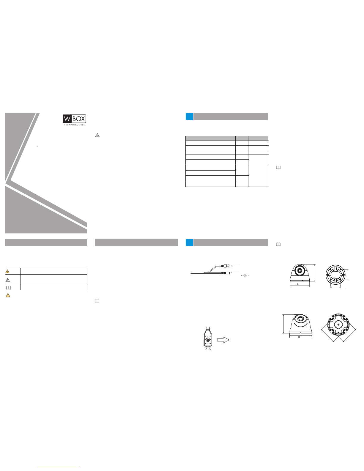
Figure 2-1 Power and video cable
2.3 Camera Dimensions(Unit:mm)
Figure 2-3 Fixed focus small Eyeball
Different device may have different dimensions, please refer
to th e .actual product
NOTE
CAUTION
WARNING
WARNING
CAUTION
Open Package Examination
1
Device Structure
2
Video
12V D C
Con nect th e BNC con necto r of the po wer or vi deo cab le to a
video signal cable and connect the other connector to a low-
voltage power cable 12V DC
Afte r insta lling t he
camera, directly connect the video cable and power cable.
2.2 Function Keys
Use rs can ca ll OSD ma in menu s throu gh mult i funct ion swi tch
control keys, and check and set camera parameters, function keys
is shown as figure 2-2.
Figure 2-2 Function keys
Up
Down
Left
Right
SET
DN
UP
Operation description
SET key: It is use d to ente r OSD men us or sel ect men u items
whe n you pre ss this k ey in the m iddle o f the mul ti func tion sw itch.
UP/DOWN keys: The UP and D OWN key s are use d to sele ct menu
items upwards and downwards by prodding the multi function
switch upwards and downwards,
LEFT/RIGHT keys: The LEF T and RIGH T keys ar e used to s elect
menu items horizontally or modify parameters by prodding the
mul ti func tion sw itch to wards t he left o r the rig ht,
the menu items rapidly roll
upwards and downwards accordingly;
the parameter
values will rapidly decrease or increase.
Pre ss and ho ld the LE FT butto n for 5s to s witch t o AHD mode .
Pre ss and ho ld the RI GHT butt on for 5s t o switc h to TVI mo de.
Pre ss and ho ld the UP bu tton fo r 5s to swi tch to CV BS mode .
Pre ss and ho ld the DO WN butt on for 5s t o switc h to CVI mo de.
94
84
48.5
48.5
NOTE
The d etail o perat ion of OS D refer t o Camera OSD Operation
Guide.
Alternative
Alternative
HD EYEBALL Camera
Quick Setup Guide
0E-HDD1MP28
0E-HDD2MP28
0E-HDDMO2812
100
119
Figure2-4 Zoom lens l arge eyeball
98
98
0E-HDD1MP28G
0E-HDD2MP28G
0E-HDDM2812G
Page 2
you ca n route c able s from the t op or fro m aside . If you us e the top
rou ting me thod, dr ill a ho le in the s urface f irst. I f the aside
routing method. When you route cables from aside,
you u se
please cut the
compression ring outlet, as shown in figure 3-3, and route the cable
out fr om the si de gap at t he bott om of the c amera .
NOTE
Figure 3-3 Cutting the compression ring outlet
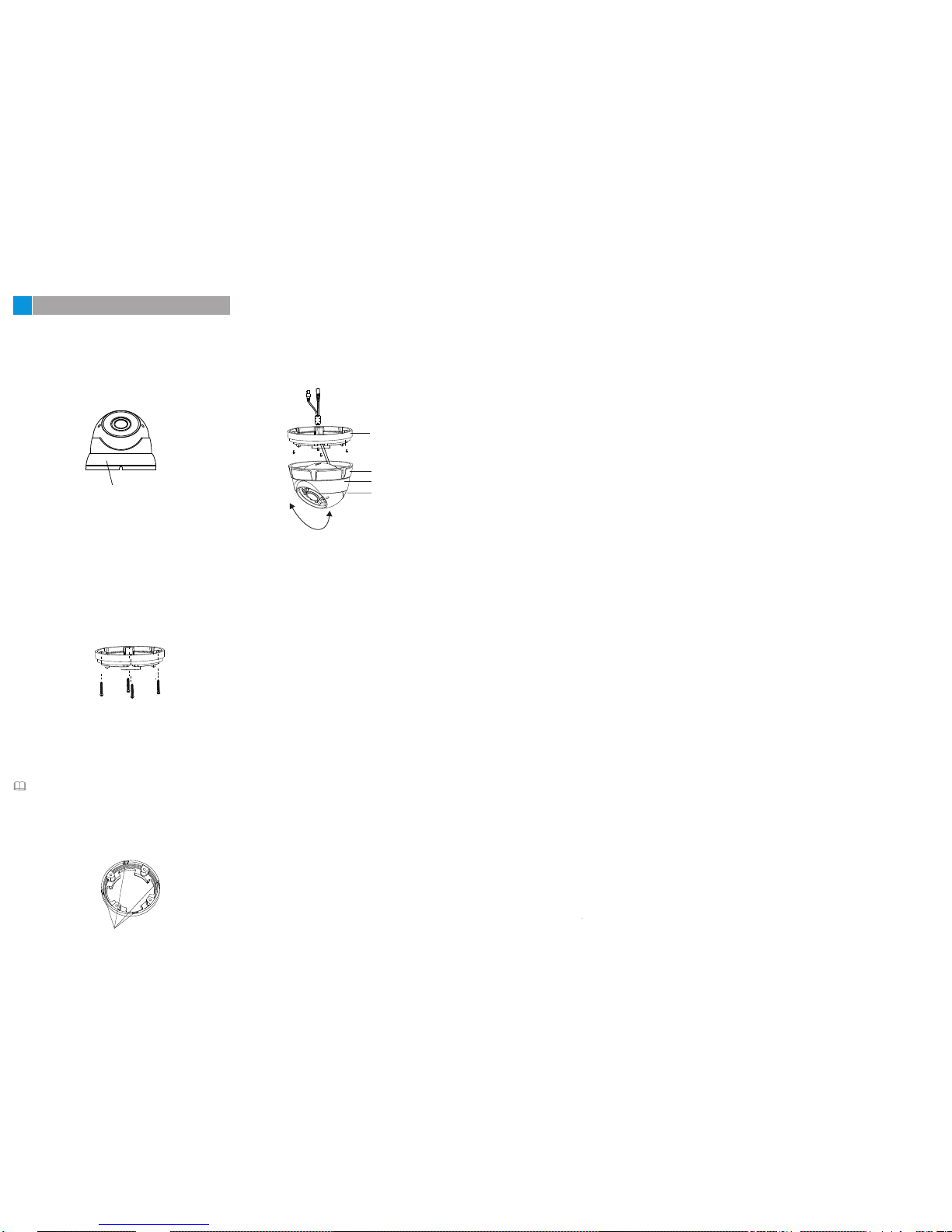
Step 4 Install the dome shell and the compression ring on the mount-
ing base, adjust the position so that the camera faces the monitored area, then tighten the screw, as shown in figure 3-4.
Figure 3-1 Removing compression ring
Ste p 2 Stick the Installation location sticker on the ceiling or wall,
Dri ll thre e holes b ased on t he mark s on the st icker. D rive
the swell plastic buttons into the holes.
Ste p 3 Fix the c amera m ounti ng base t o the mou nting s urfac e, by
use of self-tapping screws, as shown in figure 3-2.
Figure 3-2 Fixing the mounting base
Installation Steps:
Ste p 1 Open a package, take out the camera and the accessories,
uns crew th e compr essio n ring or u se the sc rewdr iver to
loosen the screw, remove the compression ring, as shown
in figure 3-1.
3
Device Installation
Compression ring
Outlet
Figure 3-4 Installing and djusting camera
Mounting base
Compression ring
Dome shell fixed base
Dome shell
If you have any questions, please call W Box Tech Support 1-
833-574-9124
for assistance.
 Loading...