

Page 1
Digital Video Recorder(DVR)
User Manual
0E-HD4C1TB
0E-HD8C2TB
0E-HD16C2TB
If you have any questions, please call
W Box Tech Support 1-833-574-9124
for assistance.
E-mail:tech@wboxsupport.com
Page 2

Page 3
Digital Video Recorder(DVR)
User Manual
Precautions
Issue V1.0 (2018-06-04) i
Precautions
Symbol
Description
It alerts you to fatal dangers which, if not avoided, may
cause deaths or severe injuries.
It alerts you to moderate dangers which, if not avoided,
may cause minor or moderate injuries.
It alerts you to risks. Neglect of these risks may cause
device damage, data loss, device performance
deterioration, or unpredictable results.
It provides a tip that may help you resolve problems or
save time.
It provides additional information.
Fully understand this document before using this device, and strictly observe rules in
this document when using this device. If you install this device in public places,
provide the tip "You have entered the area of electronic surveillance" in an eyecatching place. Failure to correctly use electrical products may cause fire and severe
injuries. To prevent accidents, carefully read the following context:
Symbols
This document may contain the following symbols whose meanings are described
accordingly.
Precautions
To prevent electric shocks or other dangers, keep power plugs dry and clean.
Strictly observe installation requirements when installing the device. The
manufacturer shall not be held responsible for device damage caused by users' nonconformance to these requirements.
Page 4

Precautions
Digital Video Recorder(DVR)
User Manual
ii Issue V1.0 (2018-06-04)
Strictly conform to local electrical safety standards and use power adapters that are
marked with the LPS standard when installing and using this device. Otherwise,
this device may be damaged.
Use accessories delivered with this device. The voltage must meet input voltage
requirements for this device.
If this device is installed in places with unsteady voltage, ground this device to
discharge high energy such as electrical surges in order to prevent the power supply
from burning out.
When this device is in use, ensure that no water or any liquid flows into the device.
If water or liquid unexpectedly flows into the device, immediately power off the
device and disconnect all cables (such as power cables and network cables) from
this device.
Do not focus strong light (such as lighted bulbs or sunlight) on this device.
Otherwise, the service life of the image sensor may be shortened.
If this device is installed in places where thunder and lightning frequently occur,
ground the device nearby to discharge high energy such as thunder strikes in order
to prevent device damage.
Avoid heavy loads, intensive shakes, and soaking to prevent damages during
transportation and storage. The warranty does not cover any device damage that is
caused during secondary packaging and transportation after the original packaging
is taken apart.
Protect this device from fall-down and intensive strikes, keep the device away from
magnetic field interference, and do not install the device in places with shaking
surfaces or under shocks.
Clean the device with a soft dry cloth. For stubborn dirt, dip the cloth into slight
neutral cleanser, gently wipe the dirt with the cloth, and then dry the device.
Do not jam the ventilation opening. Follow the installation instructions provided in
this document when installing the device.
Keep the device away from heat sources such as radiators, electric heaters, or other
heat equipment.
Keep the device away from moist, dusty, extremely hot or cold places, or places
with strong electric radiation.
If the device is installed outdoors, take insect- and moisture-proof measures to
avoid circuit board corrosion that can affect monitoring.
Remove the power plug if the device is idle for a long time.
Before unpacking, check whether the fragile sticker is damaged. If the fragile
sticker is damaged, contact customer services or sales personnel. The manufacturer
shall not be held responsible for any artificial damage of the fragile sticker.
Page 5

Digital Video Recorder(DVR)
User Manual
Precautions
Issue V1.0 (2018-06-04) iii
Special Announcement
All complete products sold by the manufacturer are delivered along with nameplates,
operation instructions, and accessories after strict inspection. The manufacturer shall
not be held responsible for counterfeit products.
This manual may contain misprints, technology information that is not accurate enough,
or product function and operation description that is slightly inconsistent with the
actual product. The manufacturer will update this manual according to product function
enhancement or changes and regularly update the software and hardware described in
this manual. Update information will be added to new versions of this manual without
prior notice.
This manual is only for reference and does not ensure that the information is totally
consistent with the actual product. For consistency, see the actual product.
Page 6

Contents
Digital Video Recorder(DVR)
User Manual
iv Issue V1.0 (2018-06-04)
Contents
Precautions .................................................................................................................... i
1 Specifications............................................................................................................ 1
2 Hard Disk .................................................................................................................. 3
2.1 Precautions ..................................................................................................................... 3
2.2 Hard Disk Recommendation .......................................................................................... 3
2.3 Approximate Video Storage Duration ............................................................................. 3
2.4 Hard Disk Installation .................................................................................................... 4
3 Operation Instruction.............................................................................................. 8
3.1 Front panel ..................................................................................................................... 8
3.2 Rear panel....................................................................................................................... 8
3.3 Startup .......................................................................................................................... 10
3.4 Powering off the Device ................................................................................................ 11
3.5 Logging In to the System .............................................................................................. 11
3.6 Changing the Password ................................................................................................ 12
3.7 Adding Cameras ........................................................................................................... 13
4 Quick Navigation ................................................................................................... 15
4.1 PTZ Operations ............................................................................................................ 17
4.1.1 PTZ .................................................................................................................. 17
4.1.2 UTC ................................................................................................................. 19
4.2 Playback ................................ ................................ ................................ ....................... 20
4.3 Search ........................................................................................................................... 21
4.4 Picture Grid .................................................................................................................. 22
4.5 Event ............................................................................................................................ 23
4.6 Main Menu ................................................................................................................... 23
5 Camera Management ............................................................................................ 25
5.1 Camera Management .................................................................................................... 26
5.1.1 Lock a Camera ................................................................................................. 26
5.1.2 Unlock a Camera .............................................................................................. 26
5.2 Picture Parameter ......................................................................................................... 27
5.3 Encode Parameter ......................................................................................................... 28
Page 7

Digital Video Recorder(DVR)
User Manual
Contents
Issue V1.0 (2018-06-04) v
5.4 Video loss ..................................................................................................................... 29
5.5 Motion Detection.......................................................................................................... 33
5.6 Privacy Area ................................................................................................................. 35
5.7 Camera tamper ............................................................................................................. 35
5.8 OSD settings................................................................................................................. 36
6 System setting......................................................................................................... 38
6.1 Basic ............................................................................................................................. 38
6.1.1 System .............................................................................................................. 39
6.1.2 Time ................................................................................................................. 39
6.1.3 Time zone ......................................................................................................... 40
6.1.4 DST .................................................................................................................. 41
6.2 Network ........................................................................................................................ 42
6.2.1 Ipv4 .................................................................................................................. 42
6.2.2 Port ................................................................................................................... 44
6.2.3 UPNP ............................................................................................................... 45
6.2.4 SMTP ................................................................ ................................ ............... 46
6.2.5 DDNS ................................................................................................ ............... 47
6.2.6 Blacklist ........................................................................................................... 48
6.3 Record .......................................................................................................................... 50
6.4 Output........................................................................................................................... 51
6.5 Alarm Manager ............................................................................................................. 54
6.5.1 Surveillance ................................ ................................................................ ...... 54
6.5.2 Alarm in ........................................................................................................... 55
6.6 Disk .............................................................................................................................. 56
6.6.1 Viewing Disk Information ................................................................................ 57
6.6.2 Clearing Disk Data ........................................................................................... 57
6.7 Privilege manager ......................................................................................................... 58
6.7.1 User manager ................................................................................................... 58
6.7.2 Modify Password ............................................................................................. 60
6.8 Privacy ......................................................................................................................... 60
6.9 Advanced setting .......................................................................................................... 61
6.10 App ............................................................................................................................. 62
7 Log Center ............................................................................................................... 64
8 Alarm ........................................................................................................................ 66
8.1 Event ............................................................................................................................ 66
8.2 Timeline ....................................................................................................................... 67
8.3 Clear alarm ................................................................................................................... 68
Page 8

Contents
Digital Video Recorder(DVR)
User Manual
vi Issue V1.0 (2018-06-04)
9 Web Access .............................................................................................................. 69
9.1 Login ............................................................................................................................ 69
9.2 Live Video .................................................................................................................... 70
9.3 Video Playback ............................................................................................................. 70
9.4 Alarm Search ................................ ................................................................ ................ 72
9.5 DVR Setting ................................................................................................................. 74
9.5.1 Viewing basic information ............................................................................... 75
9.5.2 Network management ...................................................................................... 76
9.5.2.1 IPv4 ............................................................................................. 76
9.5.2.2 Port .............................................................................................. 77
9.5.2.3 DDNS .......................................................................................... 78
9.5.2.4 SMTP .......................................................................................... 79
9.5.3 Device management ......................................................................................... 80
9.6 Alarm ............................................................................................................................ 82
9.7 Storage.......................................................................................................................... 84
9.8 User .............................................................................................................................. 85
9.8.1 Privilege management ...................................................................................... 85
9.8.2 Modify password ................................ ................................ .............................. 88
9.8.3 Local ................................................................................................................ 88
10 FAQ ........................................................................................................................ 90
Page 9
Digital Video Recorder(DVR)
User Manual
1 Specifications
Issue V1.0 (2018-06-04) 1
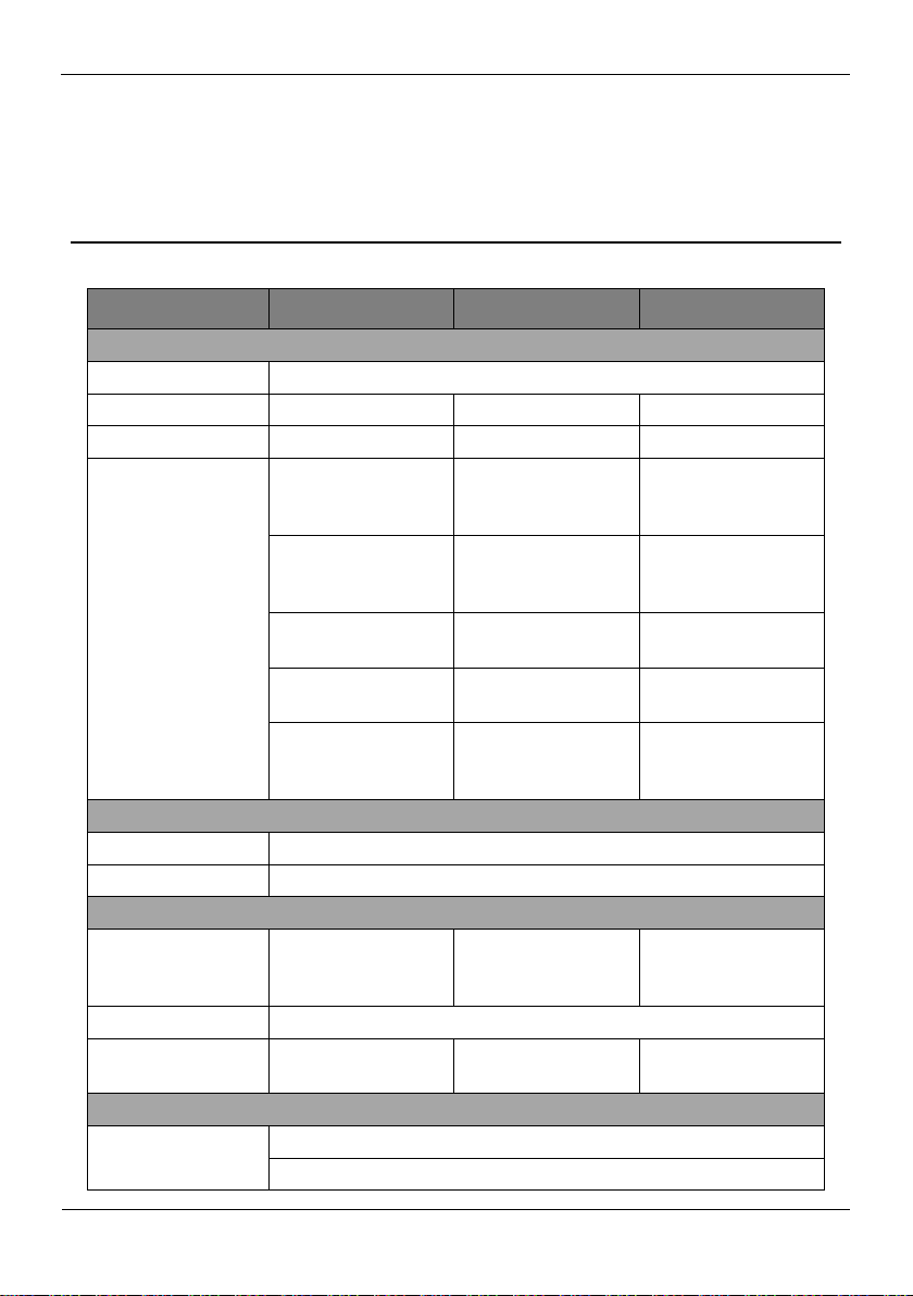
1 Specifications
Model
0E-HD4C1TB
0E-HD8C2TB
0E-HD16C2TB
VIDEO
Video Compression
H.264 High Profile
Encode Ability
4ch*1080P@15fps
8ch*1080P@15fps
16ch*1080P@15fps
Decode Ability
4ch *1080P@15fps
8ch*1080P@15fps
16ch*1080P@15fps
Video Input
Pure Analog:
4ch*1080P/4ch*720
P
Pure Analog:
8ch*1080P/8ch*720
P
Pure Analog:
16ch*1080P/8ch*72
0P
Mixed Input:
4ch*1080P(AHD+T
VI+CVI)
Mixed
Input:8ch*1080P(A
HD+TVI+CVI)
Mixed
Input:16ch*1080P(
AHD+TVI+CVI
4ch*1080P(AHD
+CVI+ Network
8ch*1080P(AHD
+CVI+ Network
16ch*1080P(AHD
+CVI+ Network)
4ch*1080P(TVI
+CVI+ Network)
8ch*1080P(TVI
+CVI+ Network)
16ch*1080P(TVI+C
VI + Network
Pure Network:
4ch*1080P/4ch*720
P
Pure Network:
8ch*1080P/8ch*720
P
Pure
Network:16*1080P/
16ch*720P
AUDIO
Audio Compression
G711A
Two Way Audio
Support
RECORD AND PLAYBACK
Hard Drive
1 SATA(Each
maximum support
6T )
2 SATA(Each
maximum support
6T )
2 SATA(Each
maximum support
6T )
Record
Manual/Event/Timer
Playback
4ch(pure local input
mode)
8ch(pure local input
mode)
16ch(pure local
input mode)
STORAGE AND BACKUP
Space Occupation
960H:12G~20G/ day*channel
720P:10G~20G/ day*channel
Page 10
1 Specifications
Digital Video Recorder(DVR)
User Manual
2 Issue V1.0 (2018-06-04)
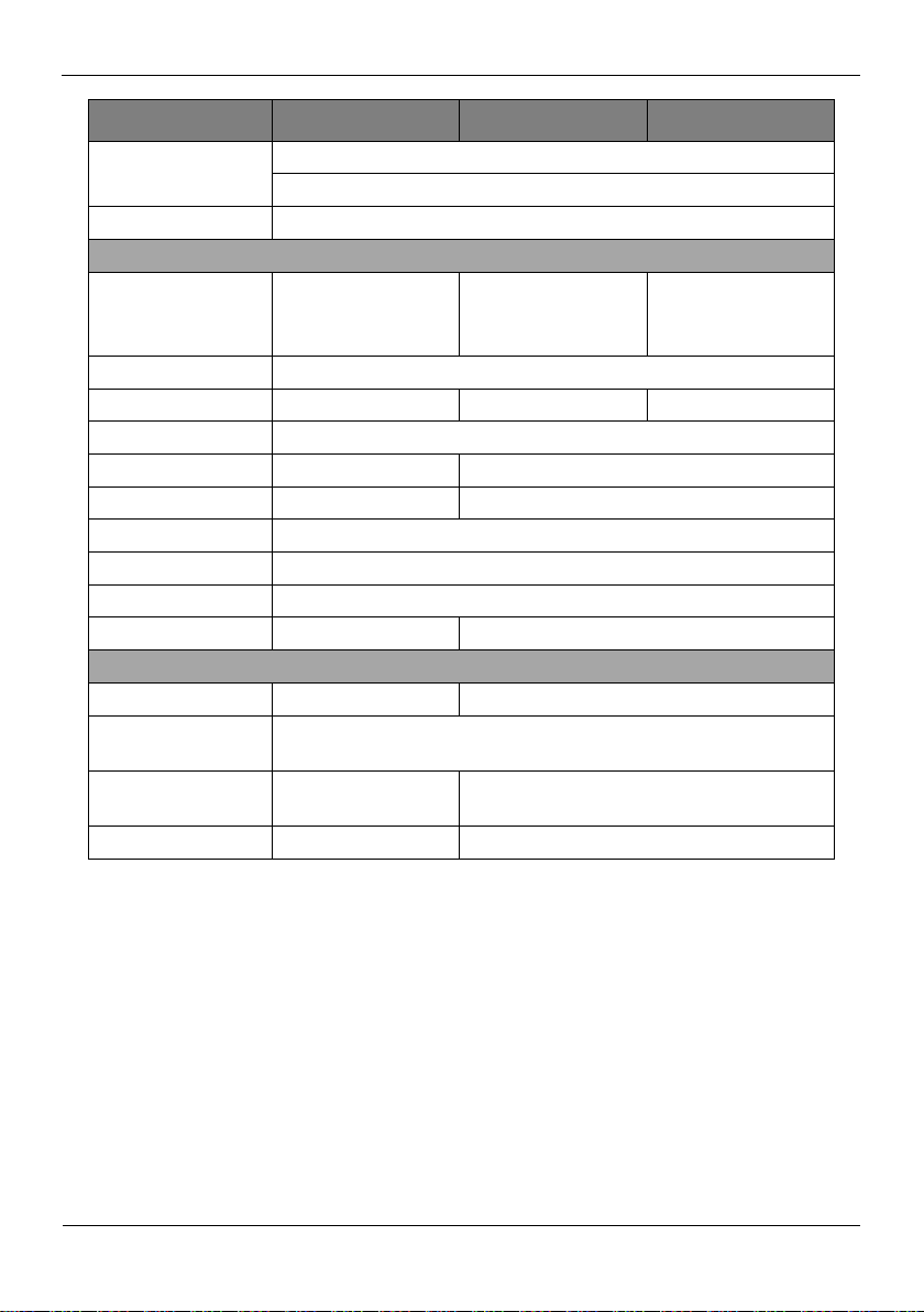
Model
0E-HD4C1TB
0E-HD8C2TB
0E-HD16C2TB
1080P: 20G~30G/ day*channel
Audio:691.2M/ day*channel
Backup Mode
USB HDD
INTERFACE
Video Input
4ch BNC
(AHD/TVI/CVI/C
VBS)
8ch BNC
(AHD/TVI/CVI/C
VBS)
16ch BNC
(AHD/TVI/CVI/C
VBS)
Video Output
1ch VGA,1ch HDMI,1ch CVBS
Audio Input
4ch RCA
8ch RCA
6ch RCA
Audio Output
1ch RCA
Alarm Input
N/A
4ch
Alarm Output
N/A
1ch
Network Interface
1 RJ45 10M/100M Adaptive Ethernet Port
PTZ Control
RS485, Support Multiple PTZ Protocols
USB
2 USB
Hard Disk
1 SATA
2 SATA
GENERAL
Power
DC12V/2A
DC12V/4A
Operating
Temperature
-10°C ~ 50°C (14°F ~ 122°F )
Dimension
255mm(L)*255mm(
W)*45mm(H)
350mm(L)* 295mm(W)*45mm(H)
Product Weight
900g
1900g
Page 11
Digital Video Recorder(DVR)
User Manual
2 Hard Disk
Issue V1.0 (2018-06-04) 3
2.1 Precautions
Maximum Hard Disk
Capacity
Maximum Bit Rate
Approximate Video
Storage Duration
1 × 6 TB
18 Mbps
28 days
2×6 TB
36 Mbps
28 days
4 × 6 TB
72 Mbps
28 days
2 Hard Disk
Formatting will clear all video data on the hard disk. Use this function only when
necessary.
Be sure to uninstall the hard disk before removing it from the DVR during runtime;
otherwise, the hard disk may be damaged or data may be lost.
The DVR must be connected to a stable power supply during runtime; otherwise,
the hard disk may be damaged or data may be lost.
The maximum capacity of a single hard disk cannot exceed 6 TB.
2.2 Hard Disk Recommendation
Seagate or Western Digital hard disks which are highly stable and inexpensive are
recommended.
2.3 Approximate Video Storage Duration
Table 2-1 Approximate Video storage duration
Formulae for calculating the approximate video storage duration:
Step 1 Use the following formula to calculate the storage capacity q (unit: MBybte)
required to record a single video per hour:
q = d/8×3600/1024
Page 12
2 Hard Disk
Digital Video Recorder(DVR)
User Manual
4 Issue V1.0 (2018-06-04)
d indicates the bit rate (unit: Kbit/s).
Hard Disk
Capacity
Bit Rate
Video Count
Approximate Video
Storage Duration
1×6TB
D1, 1.5Mbps
4
85 days
1×6TB
720p, 3Mbps
4
47 days
1×6TB
1080p, 4.5Mbps
4
28 days
2×6TB
D1, 1.5Mbps
8
85 days
2×6TB
720p, 3Mbps
8
47 days
2×6TB
1080p, 4.5Mbps
8
28 days
4×6TB
D1, 1.5Mbps
16
85 days
4×6TB
720p, 3Mbps
16
47 days
4×6TB
1080p, 4.5Mbps
16
28 days
Step 2 Use the following formula to calculate the approximate video storage duration t
(unit: day)
w indicates the capacity (unit: Mbyte) of a single hard disk.
n indicates the number of disks.
h indicates the recording duration per day.
c indicates the number of video inputs of the DVR.
Table 2-2 shows examples of approximate video storage duration (h is 24 hours).
Table 2-2 Examples of approximate video storage duration
The data listed in the preceding table is only for your reference. The recording time estimate
may be different from the actual recording time. The user shall be liable for any loss
incurred as a result thereof.
2.4 Hard Disk Installation
Take the following steps to install a hard disk:
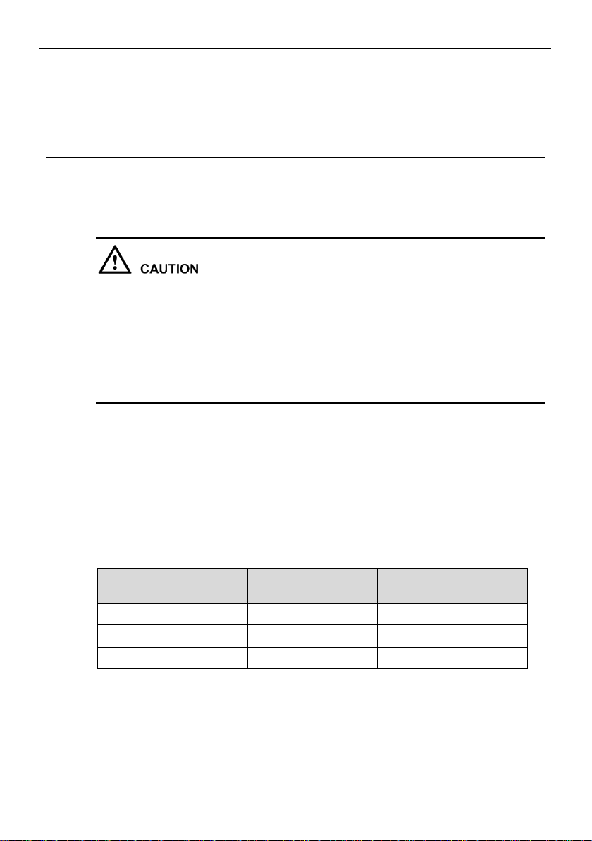
Step 1 Unscrew the four fixing screws on both sides and one fixing screw on the back, then
remove the upper cover, as shown in Figure 2-1.
Page 13
Digital Video Recorder(DVR)
User Manual
2 Hard Disk
Issue V1.0 (2018-06-04) 5
Figure 2-1 Removing the upper cover
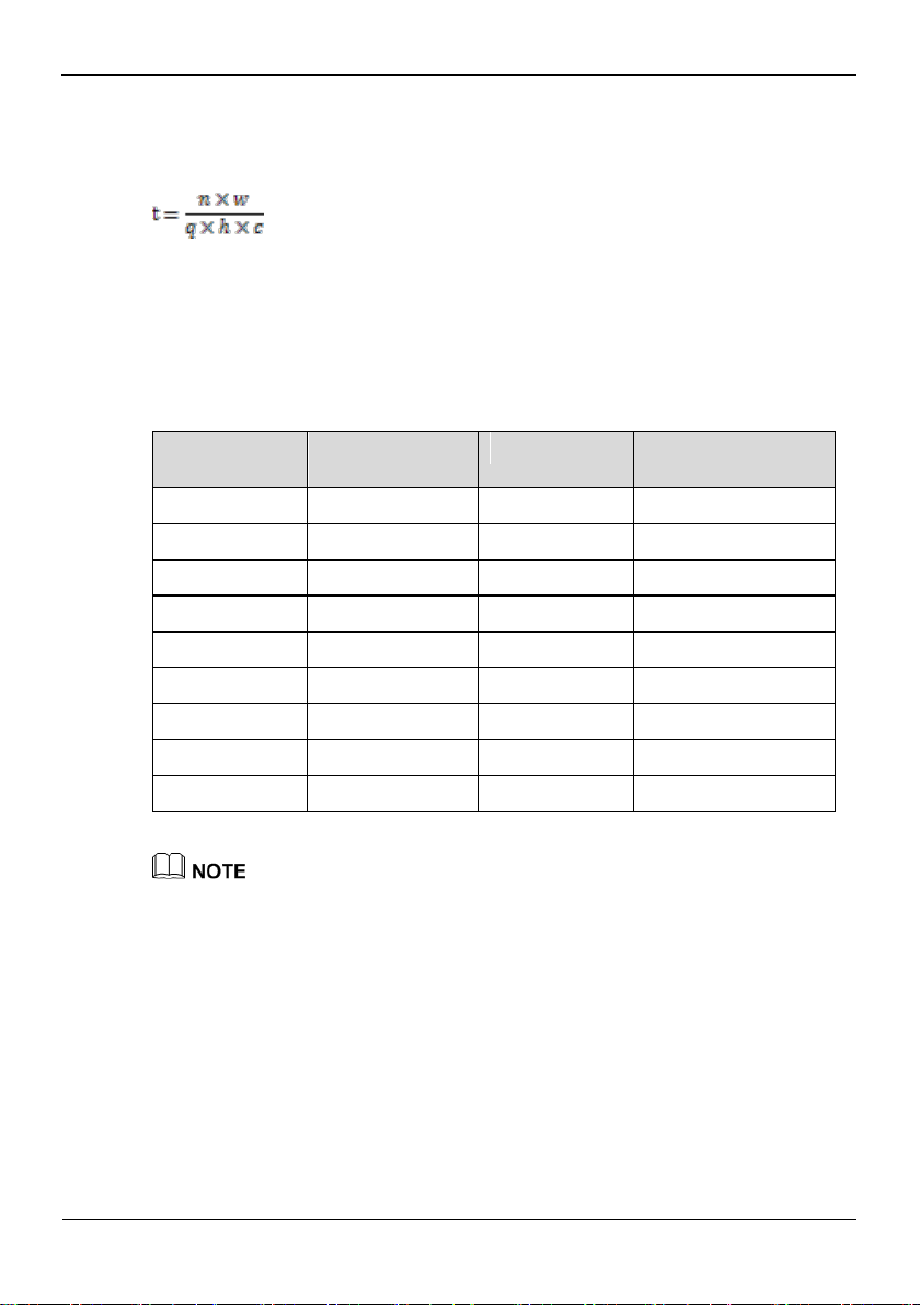
Step 2 Take out the hard disk fixing screws and silicone cushion included in the accessory
package, route the fixing screw through the silicone cushion, and install it to the screw
holes, as shown in Figure 2-2.
Figure 2-2 Installing the hard disk fixing screw
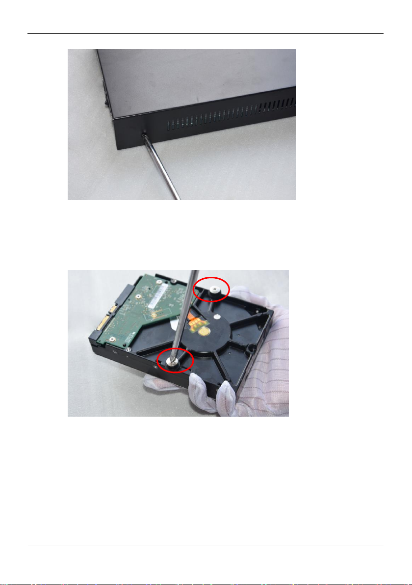
Step 3 Route the hard disk fixing screws through the holes on the base, push the hard disk to
the appropriate position according to the direction of arrow, as shown in Figure 2-3.
Page 14
2 Hard Disk
Digital Video Recorder(DVR)
User Manual
6 Issue V1.0 (2018-06-04)
Figure 2-3 Inserting the hard disk
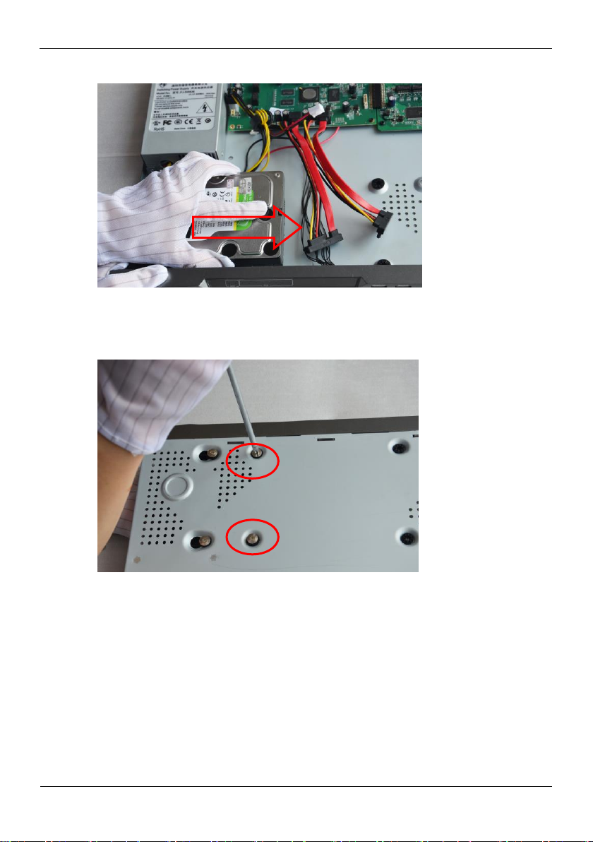
Step 4 Turn the device over, and fasten two hard disk fixing screws, as shown in Figure 2-4.
Figure 2-4 Fixing the hard disk
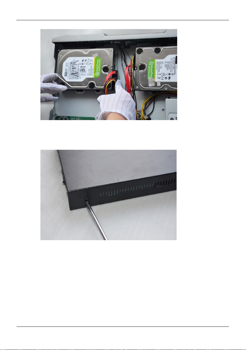
Step 5 Install the other hard disk according to Step 2, Step 3, and Step 4, then insert the hard
disk data cable and power cable, as shown in Figure 2-5.
Page 15
Digital Video Recorder(DVR)
User Manual
2 Hard Disk
Issue V1.0 (2018-06-04) 7
Figure 2-5 Inserting the cable
Step 6 Put on the upper cover, and fasten the fixing screws, as shown in Figure 2-6.
Figure 2-6 Put on the upper cover
----End
Page 16
3 Operation Instruction
Digital Video Recorder(DVR)
User Manual
8 Issue V1.0 (2018-06-04)
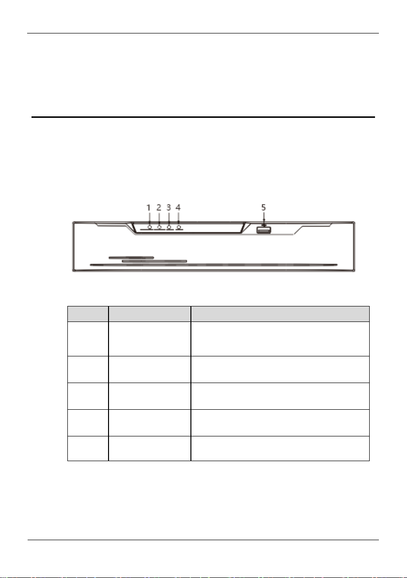
3.1 Front panel
NO.
Element
Description
1
POWER
Power indicator, When DVR is operating, the
Power indicator is steady on. When DVR is
shut down, the PWR indicator is turned off.
2
ALARM
Alarm indicator
This indicator flashes when alarm is transmitted
3
REC
Record indicator
This indicator flashes when DVR is recording
4
NET
Net indicator
This indicator flashes when DVR record
5
USB
Supports connection to a USB mouse, a USB
flash drive or USB removable hard disk.
Figure 3-1 shows the front panel of DVR. Table 3-1 shows the description of front
panel.
Figure 3-1 Front panel
Table 3-1 Elements of the front panel
3 Operation Instruction
3.2 Rear panel
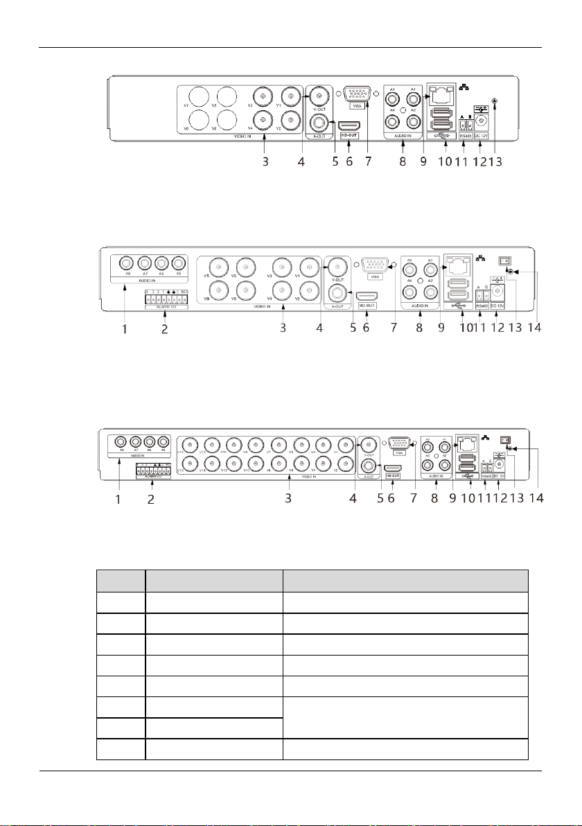
Figure 3-2 shows the rear panel of 0E-HD4C1TB and the interfaces on it.
Page 17
Digital Video Recorder(DVR)
User Manual
3 Operation Instruction
Issue V1.0 (2018-06-04) 9
Figure 3-2 Rear panel of 0E-HD4C1TB
NO.
Name
Description
1
AUDIO IN
Audio Input
2
ALARM I/O
Alarm Input/Output
3
VIDEO IN
Video input
4
CVBS
CVBS output interface
5
A-OUT
Audio output
6
HD-OUT
Video output interface
7
VGA
8
AUDIO IN
Audio Input
Figure 3-3 shows the rear panel of 0E-HD8C2TB and the interfaces on it.
Figure 3-3 Rear panel of 0E-HD8C2TB
Figure 3-3 shows the rear panel of 0E-HD16C2TB and the interfaces on it.
Figure 3-4 Rear panel of 0E-HD16C2TB
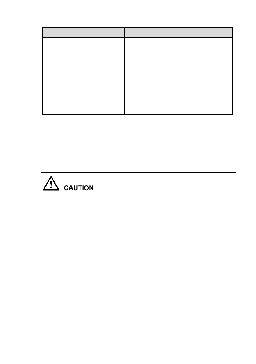
Table 3-2 shows the description of rear panel
Table 3-2 Elements of the real panel
Page 18
3 Operation Instruction
Digital Video Recorder(DVR)
User Manual
10 Issue V1.0 (2018-06-04)
NO.
Name
Description
9
LAN network
interface
RJ45 10 /100/1000 Mbps adaptive
Ethernet interface
10
USB
Supports connection to a USB mouse, a USB
flash drive or USB removable hard disk.
11
RS485
RS485 port
12
DC power
interface
Connected to an external power adapter
13
Power switch
-(Optional for different DVR)
14
Ground screw
Safe ground screw of the device
3.3 Startup
Before starting the DVR, ensure that the DVR is connected to a power supply.
When the DVR is connected to a power supply, it starts automatically upon the initial
power-on.
Ensure that a power supply is connected to the DVR correctly.
Before starting the DVR, ensure that a monitor is connected to the HD-OUT or
VGA interface of the DVR correctly.
The DVR may not operate normally when a power supply exception occurs, likely
causing damage to the DVR in serious conditions. In such a circumstance, you are
advised to use a regulated power supply.
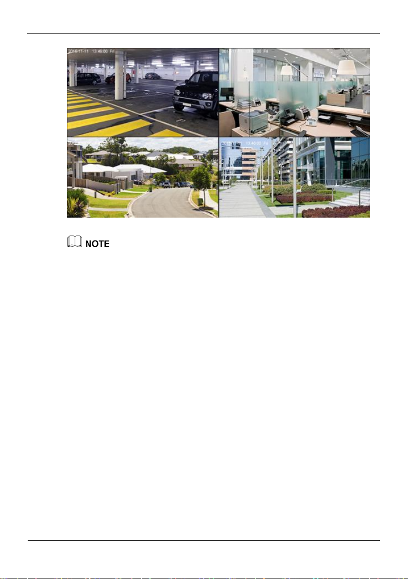
After the DVR is connected to a power supply, the power indicator is steadily on. Start
the DVR. The real-time video screen is displayed, as shown in Figure 3-5.
Page 19
Digital Video Recorder(DVR)
User Manual
3 Operation Instruction
Issue V1.0 (2018-06-04) 11
Figure 3-5 Real-time video screen
Users need to provide a hard disk for the DVR. The hard disk is strictly detected during
device startup. If the detection result failed, the possible causes are as follows:
The hard disk is new and is not formatted. Log in to the system and format the hard disk.
The hard disk is formatted, but the file system is inconsistent with the file system
supported by the DVR. Format the hard disk.
The hard disk is damaged.
3.4 Powering off the Device
Click the main menu and choose System setting > Advanced setting, the advanced
setting page is displayed, click shutdown to power off the DVR. If there is a power
switch on the rear panel of the DVR, you can turn off the power switch to disconnect
the DVR from the power supply.
3.5 Logging In to the System
Logging In to the Device
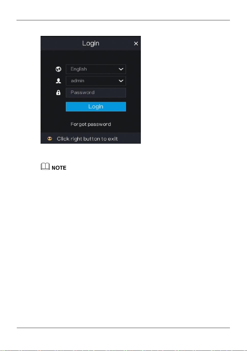
Step 1 On the DVR login page, select the language, as shown in Figure 3-6.
Page 20
3 Operation Instruction
Digital Video Recorder(DVR)
User Manual
12 Issue V1.0 (2018-06-04)
Figure 3-6 Login page
Step 2 Enter the username and password.
The username and password are both admin.
If you forget password, click Forgot password. You can choose a way to find previous
password:
1. Scan the QR code and send the QR code to your seller.
2. Click Send Password to you E-mail. A password retrieval email will be sent to your
email address (for details, see 6.2.4 Step 6). Then, you can retrieve password by
following operations described in the email.
Step 3 Click Login to access the main User Interface (UI).
----End
3.6 Changing the Password
Description
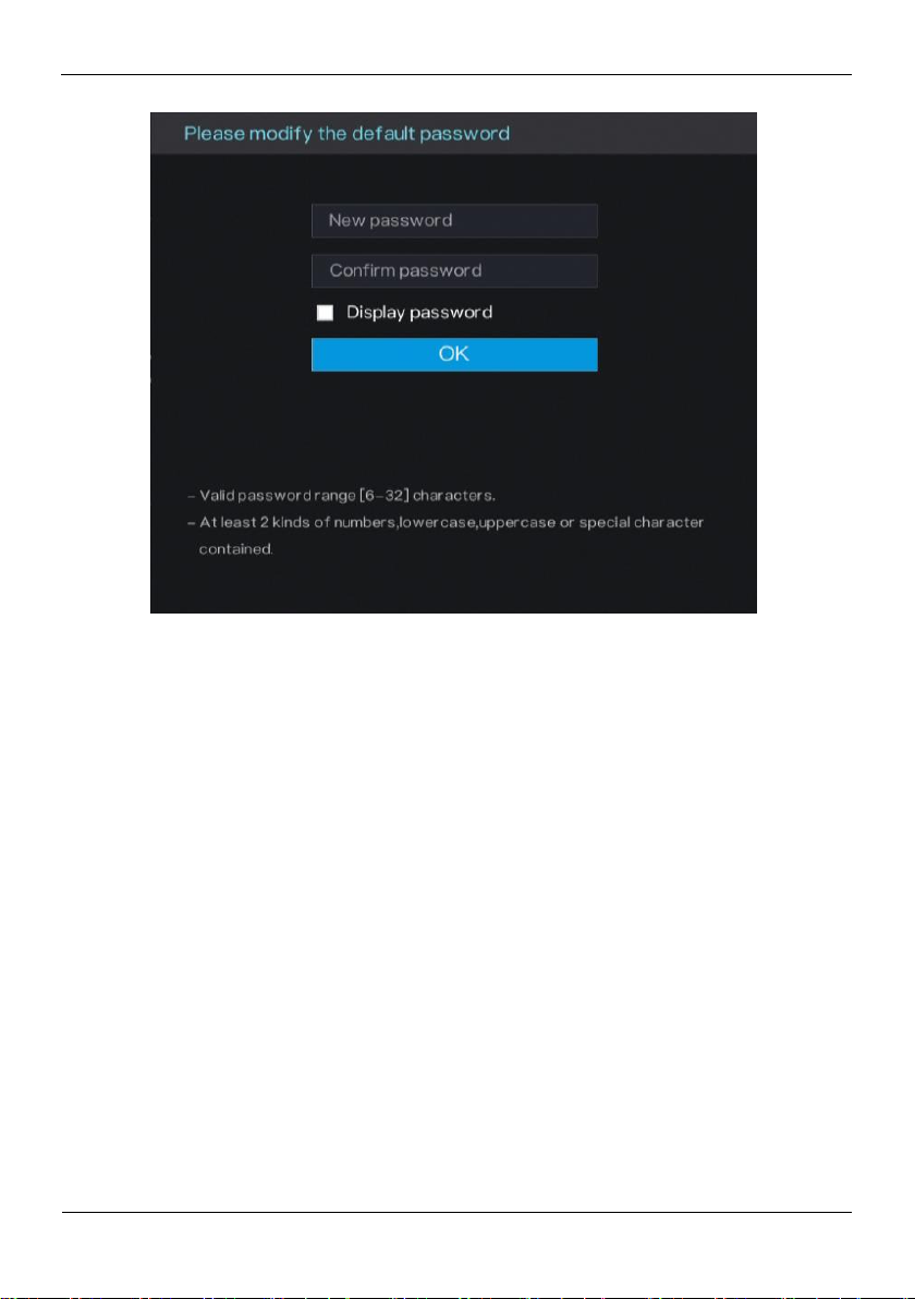
The change default password page will be displayed as shown in Figure 3-7, when you
login the system for the first time.
Page 21
Digital Video Recorder(DVR)
User Manual
3 Operation Instruction
Issue V1.0 (2018-06-04) 13
Figure 3-7 Change the default password page
Operation Steps
Step 1 Enter the new password, and confirmation password.
Step 2 Click OK.
The real-time video screen is displayed
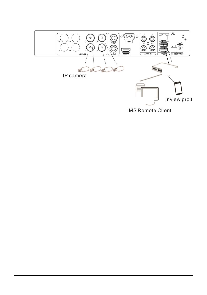
3.7 Adding Cameras
This DVR can be connected to both analog cameras and network cameras. The DVR
gives preference to the access of the analog camera by default.
The DVR can be directly connected to analog cameras through bayonet nut connector
(BNC) cables.
Figure 3-8 shows the topology of the DVR.
Page 22
3 Operation Instruction
Digital Video Recorder(DVR)
User Manual
14 Issue V1.0 (2018-06-04)
Figure 3-8 DVR topology
Switch
Remote monitor
----End
Page 23
Quick Navigation
Digital Video Recorder(DVR)
User Manual
Issue V1.0 (2018-06-04) 15
4 Quick Navigation
After the DVR operation screen is displayed, move the cursor to the downmost position
of the DVR screen. The DVR floating menu bar is displayed.
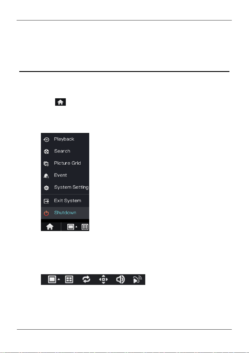
Click in the left of DVR floating menu bar. a quick main menu is displayed. The
quick main menu provides Playback, Search, Picture Grid, Event, System Setting,
Exit System and Shutdown, as shown in Figure 4-1.
Figure 4-1 Quick main menu
In the middle of DVR floating menu bar, the video tool bar provides video window
switching, Dwell on, pan-tilt-zoom (PTZ) control, audio, and video signal, as
shown in Figure 4-2.
Figure 4-2 Real-time video toolbar
The real-time video toolbar is described as follows:
Page 24
Digital Video Recorder(DVR)
User Manual
Quick Navigation
16 Issue V1.0 (2018-06-04)
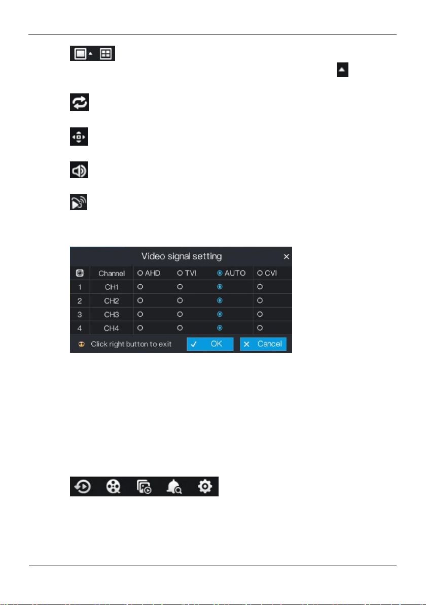
: layout button. After this button is clicked, the real-time video window is
switched between the single-screen mode and multi-screen mode. Click on the
right of screen splitting format and choose the channels to view the video.
: Dwell on, After this button is clicked, the layout dwell on screen is enable, for
how to set the dwell on, please see 6.4 Step 2.
: PTZ button. After this button is clicked, the PTZ operation screen is displayed,
where you can adjust the PTZ to control cameras.
: Audio button. After this button is clicked, the audio setting screen is displayed,
where you can choose the channel and adjust the volume.
: Video signal button. After this button is clicked, the video signal setting screen is
displayed, as show in Figure 4-3.
Figure 4-3 Video signal setting
Normally, DVR video signal setting is auto by default, the DVR obtains the video
signal of analog camera automatically.
When the video is displayed incorrectly, choose the same video signal according to the
video signal of analog camera and click OK to save the signal setting.
A main menu quick toolbar is display on the right of DVR floating menu bar. The main
menu quick toolbar provides Playback, Search, Picture grid, Event, System setting,
as shown in Figure 4-4.
Figure 4-4 Main menu quick toolbar
Page 25
Quick Navigation
Digital Video Recorder(DVR)
User Manual
Issue V1.0 (2018-06-04) 17
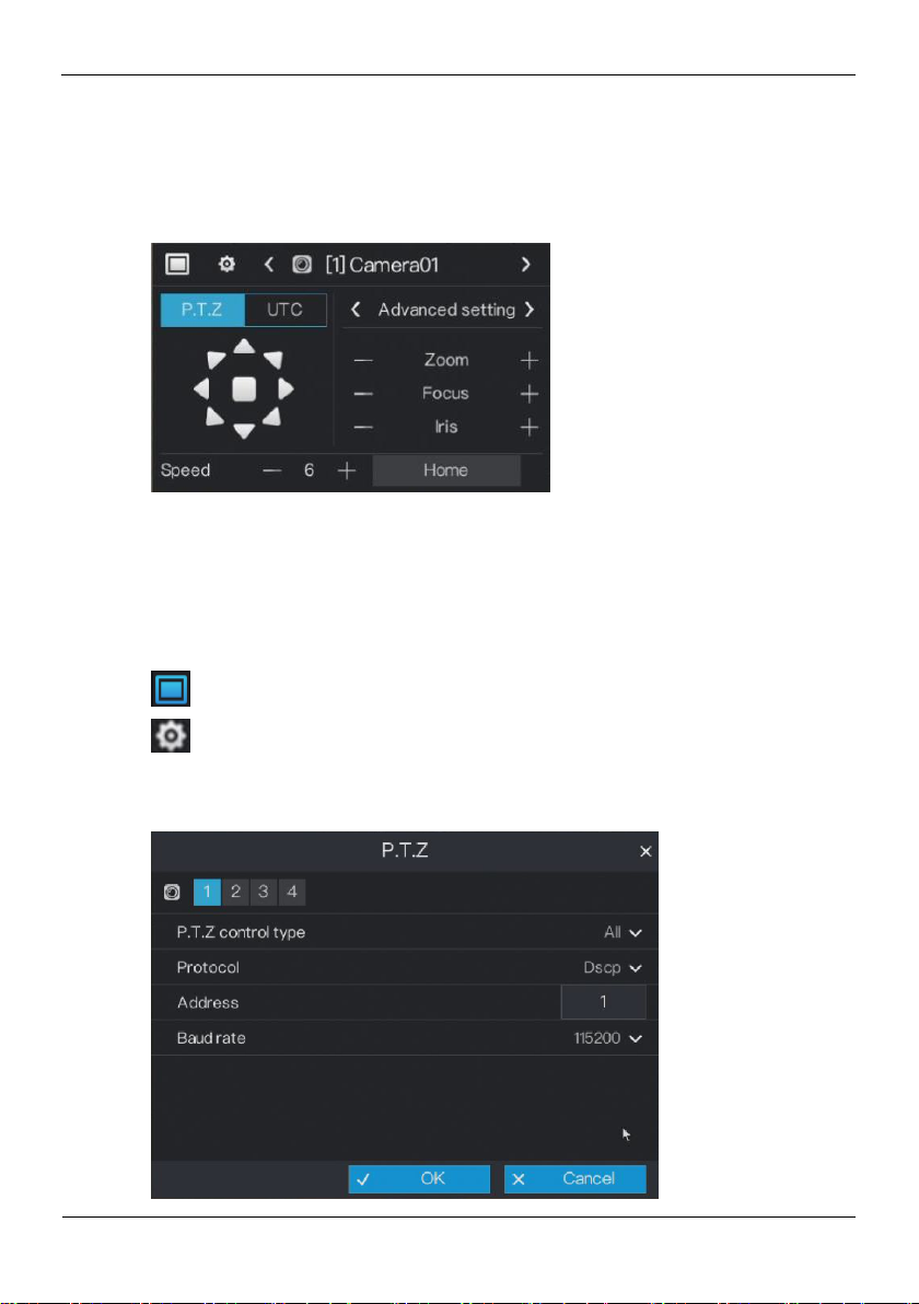
4.1 PTZ Operations
Click the PTZ button on the real-time video toolbar. The PTZ control page is displayed,
as shown in Figure 4-5.
Figure 4-5 PTZ control
4.1.1 PTZ
The PTZ control and function settings are applicable only to high-speed dome, PTZ
cameras and cameras externally connected to PTZs,
The function in the PTZ control screen is described as follows:
: layout button. After this button is clicked, the real-time video window is switched.
: PTZ setting button. After this button is clicked, the PTZ setting page is displayed,
as shown in Figure 4-6.
Figure 4-6 PTZ setting
Page 26
Digital Video Recorder(DVR)
User Manual
Quick Navigation
18 Issue V1.0 (2018-06-04)
Operation Steps
Step 2 Select a P.T.Z control type from the drop-down list box.
RS485: Use RS485 protocol to control analog high-speed domes and analog cameras
with Motorized zoom lenses.
Coaxial: Use coaxial protocol to control analog high-speed domes and analog cameras
with Motorized zoom lenses.
All: Math the RS485 or coaxial protocol automatically to control analog high-speed
domes and analog cameras with Motorized zoom lenses.
Step 3 Select a type of protocol from the drop-down list box.
Step 4 Set an address.
Step 5 Select a baud rate from the drop-down list box.
Step 6 Click OK to save P.T.Z setting or click cancel to cancel the P.T.Z setting.
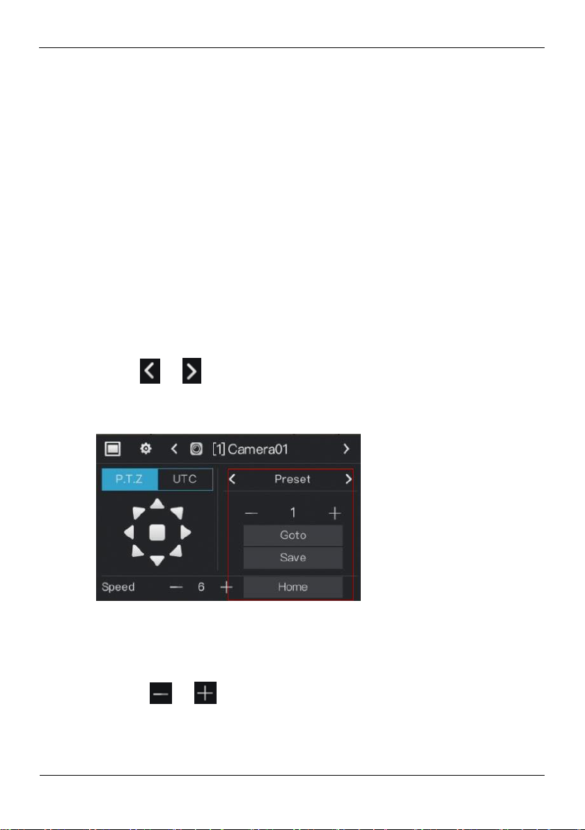
Preset
You can configure preset positions and quickly rotate the camera to a preset position by
invoking the preset position.
Click or of Advanced setting, the preset setting page is displayed, as the
red frame shown in Figure 4-7.
Figure 4-7 . PTZ setting
Operation Steps
Step 1 Set preset.
1. Click or to set the preset ID.
2. Click direction button to rotate the camera to a position and click Save to save the
preset.
Step 2 Invoke preset.
Page 27

Quick Navigation
Digital Video Recorder(DVR)
User Manual
Issue V1.0 (2018-06-04) 19
1. Select the preset ID.
2. Click Goto to invoke preset, the camera rotate the preset position.
4.1.2 UTC
The UTC control and function settings are applicable to front-end HD camera and OSD
operation of front-end HD camera.
Click UTC in PTZ control page, the UTC screen is displayed, as shown in Figure 4-8.
Or click Home to rotate the camera to the first preset position.
: Channel button. Click or to select the P.T.Z control channel.
: Click or to enter the preset setting page.
: direction button. Click this button to rotate the position of camera..
: Click or to set the camera speed.
: Click or to zoom the lens in or out.
: Click or to adjust the focal length.
: Click or to adjust the aperture.
Figure 4-8 UTC screen
For HD camera of Motorized lens, click or of zoom, focus and iris to
adjust the view angle and focal length.
For details of OSD operation, see Camera OSD Operation Guide.
Page 28
Digital Video Recorder(DVR)
User Manual
Quick Navigation
20 Issue V1.0 (2018-06-04)
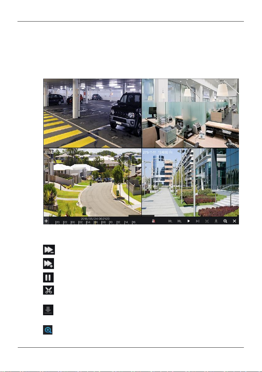
4.2 Playback
Playback refers to playing back a video.
Click Playback in the quick navigation bar to access the playback screen, as shown in
Figure 4-9.
Figure 4-9 Playback screen
The toolbar at the bottom of the playback screen is described as follows:
: Slow play
: Fast forward
: Pause
: Backup. After this button is clicked, the video backup starts. This function is
available after a USB flash drive is connected to the DVR.
: Download. After this button is clicked, the backup ends. This function is
available after the backup function is enabled.
: Magnify. Apply only to a single screen. After this button is clicked, the image
magnified to 150%, click this button again to restore the original size.
Page 29
Quick Navigation
Digital Video Recorder(DVR)
User Manual
Issue V1.0 (2018-06-04) 21
: Full screen off. After this button is clicked, the device returns to the real-time
video screen.
: Indicates whether to insert a USB flash drive. indicates that a USB flash
drive is inserted into the DVR. indicates that no USB flash drive is inserted into
the DVR.
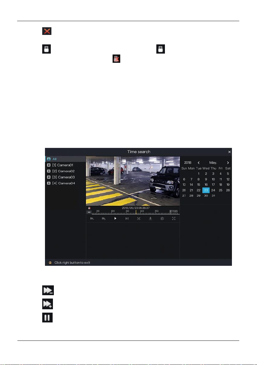
4.3 Search
Search refers to searching for a video by date and time.
Operation Description
Click Search in the quick navigation bar to access the search screen, as shown in
Figure 4-10.
Figure 4-10 Search screen
The toolbar at the bottom of the play window is described as follows:
: Slow play
: Fast forward
: Pause
Page 30
Digital Video Recorder(DVR)
User Manual
Quick Navigation
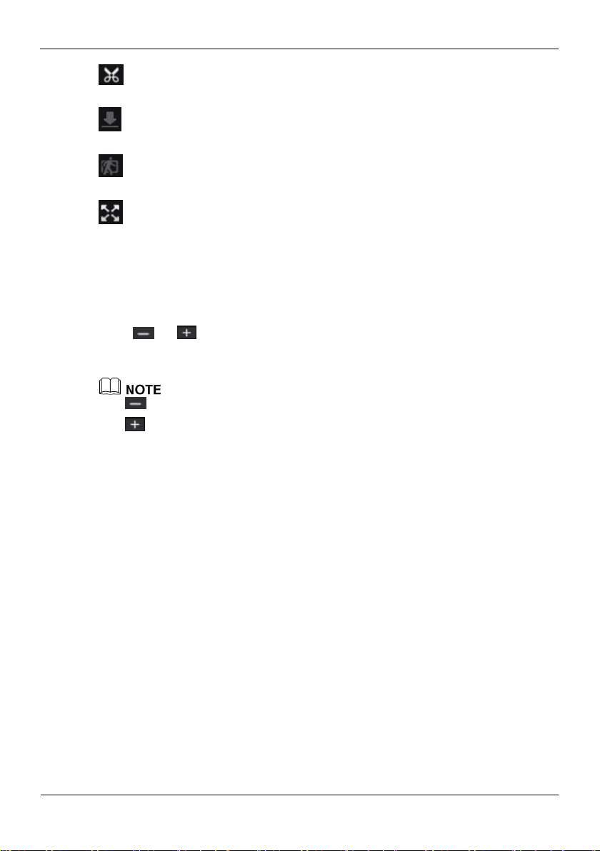
22 Issue V1.0 (2018-06-04)
: Backup. After this button is clicked, the video backup starts. This function is
available after a USB flash drive is connected to the DVR.
: Download. After this button is clicked, the backup ends. This function is available
after the backup function is enabled.
: Intelligent motion detection. After this button is clicked, the device automatically
locates a moving target.
: Full screen. After this button is clicked, the device plays a video in full screen.
Operation Steps
Step 1 Click a camera in the camera list on the left side of the search screen. The video view
of the selected camera is displayed in the play window.
Step 2 Select a date in the calendar on the right side of the search screen.
Click or on the left side of the time axis below the play window to switch
the time axis, and then select time. Then, the play window plays the video in the
specified time range.
: Videos are searched on an hourly basis.
: Videos are searched on 24 hourly basis.
----End
4.4 Picture Grid
Picture grid refers to evenly dividing the video of a channel by time range and
searching for a video based on thumbnails divided by time range.
Click Picture Grid on the quick navigation bar to access the picture grid screen, as
shown in Figure 4-11.
Page 31

Quick Navigation
Digital Video Recorder(DVR)
User Manual
Issue V1.0 (2018-06-04) 23
Figure 4-11 Picture grid screen
Operation Steps
Step 1 Select a camera in the camera list on the left side of the picture grid screen. Videos shot
by the camera in the earliest time range on the current day are displayed as thumbnails
in the window on the right side.
Step 2 Select a day of a week on the right of .
Step 3 Select a time range on the right of . For example, if you select 7, it indicates that
the selected time range is 07:00:00-08:00:00.Videos in this time range are displayed as
12 thumbnails at an interval of 5 minutes in the window on the right.
Step 4 Select a required thumbnail, double-click it or right-click it and choose Play from the
shortcut menu to play the video.
----End
4.5 Event
Click Event on the quick navigation bar to access the alarm event screen. For details
about the screen and operations on this screen, see 8.1 "Event".
4.6 Main Menu
Right-click on the main UI. The main menu as shown in Figure 4-12 is displayed. The
main menu includes Camera, Setting, Log Center, and Alarm.
Page 32

Digital Video Recorder(DVR)
User Manual
Quick Navigation
24 Issue V1.0 (2018-06-04)
Figure 4-12 DVR main menu
----End
Page 33

Camera Management
Digital Video Recorder(DVR)
User Manual
Issue V1.0 (2018-06-04) 25
Camera management mainly involves analog cameras and network cameras. Analog
cameras can be directly connected to input channels of the DVR. When analog cameras
are insufficient, the DVR automatically searches for and adds network cameras in the
same Local Area Network (LAN).
Camera management includes camera add or delete, picture parameter, encode
parameter, video loss, motion detection, privacy area, camera tamper, and setup OSD.
Operation Description
Click Camera in the main menu to access the camera management screen, as shown in
Figure 5-1.
Figure 5-1 Camera management screen
5 Camera Management
Page 34

Digital Video Recorder(DVR)
User Manual
Camera Management
26 Issue V1.0 (2018-06-04)
5.1 Camera Management
5.1.1 Lock a Camera
On the camera management screen, check the locking status of network cameras in the
camera list on the right side. If the locking status of a network camera is , you can
lock the camera manually.
Operation Steps
Step 1 Select a network camera to be locked in the camera list on the right side. The real-time
video and basic information of the network camera are displayed on the left side.
Step 2 Click the button next to Lock below the play window. The button turns blue and the
locking status is changed to in the camera list on the right side, click OK,
indicating that the camera is locked successfully.
Analog addresses directly connected to the DVR are locked preferentially and are
assigned the IP address 127.0.0.1. When channels of the DVR are insufficient for the
access of analog cameras, they automatically occupy the channels of network cameras.
If all channels of the DVR are bound to cameras, you need to unbind cameras that do not
need to be bound.
You can choose Click Add to automatically add cameras of all idle channels.
If a network camera is added, enter the username and password of the camera below the
play window. The video of the camera can be viewed only after successful login.
5.1.2 Unlock a Camera
Operation Steps
Step 1 Select a camera to be unlocked in the camera list on the right side. Information about
the camera is displayed below the play window.
Step 2 Click the button next to Lock below the play window. The button turns white and the
locking status is changed to in the camera list on the right side, indicating that
the camera is unlocked successfully.
If you click Clear, a message as shown in Figure 5-2 is displayed. Click OK to unbind
network cameras of all channels of the DVR.
Page 35

Camera Management
Digital Video Recorder(DVR)
User Manual
Issue V1.0 (2018-06-04) 27
Figure 5-2 Unlock confirmation message
5.2 Picture Parameter
Picture parameters refer to basic attributes of a picture, including the lightness,
saturation, contrast, and sharpness. You can set picture parameters for each channel
based on scenarios.
Operation Description
Click Picture Param next to Camera in the main menu or click Menu in the upper
left corner of the camera management screen and choose Picture Param to access the
Picture Parameter screen, as shown in Figure 5-3.
Figure 5-3 Picture Parameter screen
The picture parameters are described as follows:
Page 36

Digital Video Recorder(DVR)
User Manual
Camera Management
28 Issue V1.0 (2018-06-04)
Brightness: picture brightness.
Saturation: brilliance of the picture color.
Sharpness: picture clarity.
Contrast: picture transparency.
Operation Steps
Step 1 Click a camera in the camera list on the left side of the Picture Parameter screen.
Step 2 Select where to install this camera from the drop-down list. The default values of
picture parameters vary with scenarios.
Step 3 Set the camera brightness, contrast, saturation, and sharpness.
Step 4 Click OK to save picture parameter settings or click Copy to all, then click OK to
apply the parameter settings to cameras of all channels.
----End
5.3 Encode Parameter
The system allows you to set the main video resolution, sub video resolution, and
image quality (low-quality, medium-quality, high-quality, or best-quality) for cameras
in a channel, and view the frame rate and stream size in Encode Parameter.
Operation Description
Click Menu in the upper left corner of the camera management screen and choose
Encode Param to access the Encode Parameter screen, as shown in Figure 5-4.
Page 37

Camera Management
Digital Video Recorder(DVR)
User Manual
Issue V1.0 (2018-06-04) 29
Figure 5-4 Encode Parameter screen
Operation Steps
Step 1 Click a camera in the camera list on the left side of the Encode Parameter screen.
Step 2 Select Main Video or Sub Video.
Step 3 Set Resolution, Quality, Frame rate, Bitrate and Bitrate type.
Step 4 Click OK to save encode parameter settings or click Copy to all , then click OK to
apply the parameter settings to cameras of all channels.
----End
5.4 Video loss
If a camera was disconnected, it will show video loss.
Operation Description
Click Menu in the upper left corner of the camera management screen and choose
Video loss to access the video loss screen, as shown in Figure 5-5.
Page 38

Digital Video Recorder(DVR)
User Manual
Camera Management
30 Issue V1.0 (2018-06-04)
Figure 5-5 Encode Parameter screen
Operation Steps
Step 1 Enable video loss.
Click next to Start video loss to enable video loss.
Step 2 Set arming time.
Click on the right of Processing method to access arming time setting screen of
processing method, as shown in Figure 5-6.
Page 39

Camera Management
Digital Video Recorder(DVR)
User Manual
Issue V1.0 (2018-06-04) 31
Figure 5-6 Arming time screen
NOTE
Step 3 Arming time setting:
Method 1:Click left mouse button to select any time point within 0:00-24:00 from
Monday to Sunday.
Method 2:Hold down the left mouse button, drag and release mouse to select the
arming time within 0:00-24:00 from Monday to Sunday.
When you select time by dragging the cursor, the cursor cannot be moved out of the time
area. Otherwise, no time can be selected.
Method 3:Click in the arming time page to select the whole day or whole week.
Deleting arming time: Click again or inverse selection to delete the selected
arming time.
Step 4 Set trigger channel.
1. Click Trigger channel tag to access trigger channel screen, as shown in Figure 5-7.
Page 40

Digital Video Recorder(DVR)
User Manual
Camera Management
32 Issue V1.0 (2018-06-04)
Figure 5-7 Trigger channel screen
.
2. Select the trigger channel of current channel.
3. Click OK to save trigger channel settings or click Cancel to cancel the settings.
Step 5 Set Processing method.
1. Click Processing method tag to access processing method screen, as shown in
Figure 5-8.
Page 41

Camera Management
Digital Video Recorder(DVR)
User Manual
Issue V1.0 (2018-06-04) 33
Figure 5-8 Processing method screen
2. Click of “Buzzer alarm”, Push message”, “Alarm message”, “Linkage
record” respectively to enable or disable these function.
3. Click OK to save processing method settings or click Cancel to cancel the settings.
Step 6 Click OK to save video loss settings or click Copy to all, then click OK to apply the
video loss settings to cameras of all channels.
----End
5.5 Motion Detection
Motion detection refers that an alarm is triggered when an image in a specified area
changes.
Operation Description
Click Menu in the upper left corner of the camera management screen and choose
Motion Detection to access the Motion Detection screen, as shown in Figure 5-9.
Page 42

Digital Video Recorder(DVR)
User Manual
Camera Management
34 Issue V1.0 (2018-06-04)
Figure 5-9 Motion Detection screen
Operation Steps
Step 1 Select a camera in the camera list on the left side of the Motion Detection screen.
Step 2 Click next to Start Motion Detection to enable motion detection.
Step 3 In the video window, hold down and drag the left mouse button to draw a motion
detection area.
Step 4 Select a value from the drop-down list next to Sensitivity.
Step 5 Click next to Processing method to access processing method screen.
For details, please see Step 2~Step 5.
Step 6 Click OK to save motion detection settings or click Copy to all, then click OK to
apply the motion detection settings to cameras of all channels.
After a motion detection area is selected, you can double-click it to delete the selected
area.
A maximum of four areas can be configured.
----End
Page 43

Camera Management
Digital Video Recorder(DVR)
User Manual
Issue V1.0 (2018-06-04) 35
5.6 Privacy Area
The system allows you to mask images in a specified area and this area is called
privacy area.
Operation Description
Click Menu in the upper left corner of the camera management screen and choose
Privacy area to access the Privacy area screen, as shown in Figure 5-10.
Figure 5-10 Privacy Area screen
Operation Steps
Step 1 Select a camera in the camera list on the left side of the Privacy area screen.
Step 2 In the video window, hold down and drag the left mouse button to draw a privacy area.
Step 3 Click OK to save privacy area settings or click Copy to all, then click OK to apply the
privacy area settings to cameras of all channels.
----End
5.7 Camera tamper
Camera Tamper refers to the occurrence of tampered or shifted in video image. An
alarm is generated if such an event occurs.
Page 44

Digital Video Recorder(DVR)
User Manual
Camera Management
36 Issue V1.0 (2018-06-04)
Operation Description
Click Menu in the upper left corner of the camera management screen and choose
Camera tamper to access the Camera tamper screen, as shown in Figure 5-11.
Figure 5-11 Camera tamper screen
Operation Steps
Step 1 Select a camera in the camera list on the left side of the camera tamper screen.
Step 2 Click next to Start camera tamper to enable camera tamper.
Step 3 Click next to Processing method to access processing method screen.
For details, please see Step 2~Step 5.
Step 4 Click OK to save camera tamper settings or click Copy to all, then click OK to apply
the camera tamper settings to cameras of all channels.
----End
5.8 OSD settings
Click Menu in the upper left corner of the camera management screen and choose
Setup OSD to access the OSD setting screen, as shown in Figure 5-12.
Page 45

Camera Management
Digital Video Recorder(DVR)
User Manual
Issue V1.0 (2018-06-04) 37
Figure 5-12 OSD setting screen
Operation Steps
Step 1 Select a camera in the camera list on the left side of the OSD setting screen.
Step 2 Click next to Time to enable or disenable OSD time setting.
Step 3 Click next to Channel to enable or disenable OSD channel setting.
Step 4 Click OK to save OSD settings or click Copy to all ,then click OK to apply the OSD
settings to cameras of all channels.
In the video window, click and drag time or channel to move to a location.
Page 46

Digital Video Recorder(DVR)
User Manual
System setting
38 Issue V1.0 (2018-06-04)
6 System setting
The system setting allows you to set basic information, network, record, output, alarms
manager, disk, privacy manager, advanced setting, and App for the system in System
Setting. Figure 6-1 shows the system setting screen.
Figure 6-1 System setting screen
6.1 Basic
The system allows you to view the firmware version, compile time and product model,
set the device name, display resolution, system language, time zone, time and date and
DST in Basic.
Page 47

System setting
Digital Video Recorder(DVR)
User Manual
Issue V1.0 (2018-06-04) 39
6.1.1 System
Operation Steps
Step 1 On the System setting screen, choose Basic > System to access the System setting
screen, as shown in Figure 6-2.
Figure 6-2 System setting screen
Step 2 Enter Device name for selected device.
Step 3 Select a proper resolution from the Display drop-down list based on the adopted
monitor.
Step 4 Select a required language from the Language drop-down list.
Step 5 Click OK to save system settings or click Cancel to cancel settings.
----End
6.1.2 Time
Operation Steps
Step 1 On the System setting screen, choose Basic > Time to access the time setting screen,
as shown in Figure 6-3.
Page 48

Digital Video Recorder(DVR)
User Manual
System setting
40 Issue V1.0 (2018-06-04)
Figure 6-3 Time setting screen
Step 2 Select a required date format from the Date Format drop-down list.
Step 3 Click next to 24 Hour to disable the 24-hour system. Then, the 12-hour system
is enabled. If 24 Hour is set to On, the 24-hour system is used and is enabled by
default.
Step 4 Click next to Sync Time to disable time synchronization. Time
synchronization is enabled by default. Time is synchronized with the PC time.
Step 5 After Sync Time is disabled, you can manually set the system time:
Click Date and scroll the mouse scroll wheel to select the year, month, and date.
1. Click Time and scroll the mouse scroll wheel to select the hour, minute, and
second.
2. Click Modify Time to save the time settings.
Step 6 Click OK to save settings or click Cancel to cancel settings.
----End
6.1.3 Time zone
Operation Steps
Step 1 On the System setting screen, choose Basic > Time zone to access the time zone
setting screen, as shown in Figure 6-4.
Page 49

System setting
Digital Video Recorder(DVR)
User Manual
Issue V1.0 (2018-06-04) 41
Figure 6-4 Time zone setting screen
Step 2 Select a required time zone from the Time Zone drop-down list.
Step 3 Click OK to save settings or click Cancel to cancel settings.
----End
6.1.4 DST
When the DST start time arrives, the device time automatically goes forward one hour. When the
DST end time arrives, the device time automatically goes backward one hour.
Operation Steps
Step 1 On the System setting screen, choose Basic > DST to access the DST setting screen,
as shown in Figure 6-5.
Page 50

Digital Video Recorder(DVR)
User Manual
System setting
42 Issue V1.0 (2018-06-04)
Figure 6-5 DST setting screen
Step 2 Click next to Daylight saving time to enable DST.
Step 3 Select start time, end time, offset time from the drop-down list respectively.
Step 4 Click OK to save settings or click Cancel to cancel settings.
----End
6.2 Network
6.2.1 Ipv4
IPv4 is the IP protocol that uses an address length of 32 bits.
Operation Steps
Step 1 On the System setting screen, choose Network > IPv4 to access the Ipv4 setting
screen, as shown in Figure 6-6.
Page 51

System setting
Digital Video Recorder(DVR)
User Manual
Issue V1.0 (2018-06-04) 43
Figure 6-6 Ipv4 setting screen
Step 2 Click next to Obtain IP automatically to enable or disable the function of
automatically getting an IP address. The function is enabled by default.
If the function is disabled, click input boxes next to IP, Netmask, and Gateway to set
the parameters as required.
Step 3 Click next to Obtain DNS Automatically to enable or disable the function of
automatically getting a DNS address. The function is enabled by default.
If the function is disabled, click input boxes next to DNS1 and DNS2, delete
original addresses, and enter new addresses.
Step 4 Click Check. The system automatically checks network settings and the dialog box as
shown in Figure 6-7 is displayed. Check and connect the network based on network
check results.
Page 52

Digital Video Recorder(DVR)
User Manual
System setting
44 Issue V1.0 (2018-06-04)
Figure 6-7 Network check screen
Step 5 Click OK to save IPv4 network settings or click Cancel to cancel settings.
----End
6.2.2 Port
Operation Steps
Step 1 On the System setting screen, choose Network > PORT to access the port setting
screen, as shown in Figure 6-8.
Page 53

System setting
Digital Video Recorder(DVR)
User Manual
Issue V1.0 (2018-06-04) 45
Figure 6-8 Port setting screen
Step 2 Set HTTP port, Data port1 and Data port2 respectively.
Step 3 Click OK to save settings or click Cancel to cancel settings.
Data Port1 used as RTSP port
Data Port2 used as video control port
After Ports is set and saved ,please click OK and Reboot. the port is set successfully.
----End
6.2.3 UPNP
Operation Steps
Step 1 On the System setting screen, choose Network > UPNP to access the port mapping
setting screen, as shown in Figure 6-9.
Page 54

Digital Video Recorder(DVR)
User Manual
System setting
46 Issue V1.0 (2018-06-04)
Figure 6-9 Port mapping setting screen
Step 2 Click next to UPNP to enable or disable the function of UPNP. The function is
enabled by default.
Step 3 After UPNP is disabled, you can manually set the HTTP port and Data port1.
Step 4 Click OK to save settings or click Cancel to cancel settings.
After UPNP button is enabled, System perform port mapping automatically.
If UPNP is set OFF, you need to forward the ports by manually on router.
----End
6.2.4 SMTP
If the Simple Mail Transfer Protocol (SMTP) function is enabled, the device
automatically sends alarm information to specified email addresses when an alarm is
generated.
Operation Steps
Step 1 On the System setting screen, choose Network > SMTP to access the SMTP setting
screen, as shown in Figure 6-10.
Page 55

System setting
Digital Video Recorder(DVR)
User Manual
Issue V1.0 (2018-06-04) 47
Figure 6-10 SMTP setting screen
Step 2 Click next to SSL to enable or disable the function of SSL. The function is
disabled by default.
Step 3 Set SMTP server and SMTP server port manually.
Step 4 Set sender E-mail, user name and password manually.
Step 5 Set E-mail for receive alarm. the message “Mail has been sent, please check” is
displayed. Open the mail, if the verification code is received, that shows the E-mail is
set successfully.
Step 6 Set E-mail for retrieve the password. the message “Mail has been sent, please check” is
displayed. Open the mail,
Step 7 if the verification code is received, that shows the E-mail is set successfully.
Step 8 Click OK to save settings or click Cancel to cancel settings.
----End
6.2.5 DDNS
Connect the specified camera to the Internet, and obtain the user name and password
for logging into the Dynamic Domain Name System (DDNS) server.
Operation Steps
Step 1 On the System setting screen, choose Network > DDNS to access the DDNS network
setting screen, as shown in Figure 6-11.
Page 56

Digital Video Recorder(DVR)
User Manual
System setting
48 Issue V1.0 (2018-06-04)
Figure 6-11 DDNS setting screen
Step 2 Click the button next to Enable to enable the DDNS function. It is disabled by default.
Step 3 Select a required value from the Protocol drop-down list.
Step 4 Click OK to save DDNS network settings or click Cancel to cancel settings.
An external network can access an address specified in the DDNS settings to access the
DVR.
----End
6.2.6 Blacklist
Set the IP address in specified network segment to allow access or prohibit access.
Operation Steps
Step 1 On the System setting screen, choose Network > Blacklist to access the blacklist
setting screen, as shown in Figure 6-12.
Page 57

System setting
Digital Video Recorder(DVR)
User Manual
Issue V1.0 (2018-06-04) 49
Figure 6-12 Blacklist screen
Step 2 Click next to Blacklist to enable or disable the function of blacklist. The
function is disabled by default.
Step 3 Select a required value from the rule type drop-down list.
Step 4 Click Add, the set the black and white list IP segment screen is displayed, as show in
Figure 6-13.
Figure 6-13 IP Address Segment screen
2. Enter value manually for Start IP address, end IP address.
3. Click OK. The system saves the settings. And the black and white list IP segment
listed in the black (white) list.
Page 58

Digital Video Recorder(DVR)
User Manual
System setting
50 Issue V1.0 (2018-06-04)
Blacklist: IP address in specified network segment to prohibit access.
Whitelist: IP address in specified network segment to allow access
Select a name in the list and click Delete to delete the name from the list.
Select a name in the list and click Edit to edit the name in the list.
Only one rule type is available, and the last rule type set is efficient.
----End
6.3 Record
Operation Steps
Step 1 On the System setting screen, choose Record to access the record screen, as shown in
Figure 6-14.
Figure 6-14 Record setting screen
Step 2 Click next to Enable schedule record to enable or disable the function of
schedule record. The function is enabled 7*24 recording by default.
Step 3 Set Schedule.
For details, please see Step 2~Step 5.
Step 4 Click OK to save record settings or click Cancel to cancel settings.
----End
Page 59

System setting
Digital Video Recorder(DVR)
User Manual
Issue V1.0 (2018-06-04) 51
6.4 Output
Operation Steps
Step 1 On the System setting screen, choose Output to access the output setting screen, as
shown in Figure 6-15.
Figure 6-15 Output setting screen
Step 2 Click next to Dwell time to access the dwell time screen, as shown in Figure 6-16.
Page 60

Digital Video Recorder(DVR)
User Manual
System setting
52 Issue V1.0 (2018-06-04)
Figure 6-16 Dwell time screen
2. Select a required value from the Dwell interval drop-down list.
3. Set layout. Click to choose layout.
4. Select dwell channel. Click the video window and select a channel from the
channel list to set the dwell channel.
5. Click OK to save dwell settings or click Cancel to cancel settings.
Step 3 Click next to CVBS output settings to access CVBS output settings screen, as
shown in Figure 6-17.
Page 61

System setting
Digital Video Recorder(DVR)
User Manual
Issue V1.0 (2018-06-04) 53
Figure 6-17 CVBS output settings screen
2. Set the display offset. Press and hold the left mouse button and drag the value bar
to set the left, up, right, down display offset of the CVBS monitor.
3. Set the display colour. Click Display colour tag to access the display colour screen,
as shown in Figure 6-18.
Page 62

Digital Video Recorder(DVR)
User Manual
System setting
54 Issue V1.0 (2018-06-04)
Figure 6-18 Display colour settings screen
4. Press and hold the left mouse button and drag the value bar to set the brightness,
contrast, chroma, saturation of the CVBS monitor.
5. Click OK to save CVBS output settings or click Cancel to cancel settings.
6.5 Alarm Manager
The system allows you to set alarm surveillance and alarm in in Alarm manager.
6.5.1 Surveillance
Operation Steps
Step 1 On the System setting screen, choose Alarm manager > Surveillance to access the
surveillance setting screen, as shown in Figure 6-19.
Page 63

System setting
Digital Video Recorder(DVR)
User Manual
Issue V1.0 (2018-06-04) 55
Figure 6-19 Surveillance setting screen
Step 2 Click next to Enable to enable the surveillance function.
Step 3 Select alarm duration from the drop-down list.
Step 4 Click OK to save surveillance settings or click Cancel to cancel settings.
----End
6.5.2 Alarm in
Operation Steps
Step 1 On the System setting screen, choose Alarm manager > Alarm in to access the alarm
in setting screen, as shown in Figure 6-20.
Page 64

Digital Video Recorder(DVR)
User Manual
System setting
56 Issue V1.0 (2018-06-04)
Figure 6-20 Alarm in setting screen
Step 2 Select a channel in alarm in.
Step 3 Click next to Enable to enable or disable the functions.
Step 4 Select Alarm type from the drop-down list.
NC: Closed alarm circuit
NO: Opened alarm circuit
Step 5 Set name.
Step 6 Set Processing method.
For details, please see Step 2~Step 5.
Step 7 Click OK to save alarm in settings or click Cancel to cancel settings.
----End
6.6 Disk
The system allows you to view the total capacity, used capacity, and SNs of disks, and
clear all video data in a disk in disk management.
Page 65

System setting
Digital Video Recorder(DVR)
User Manual
Issue V1.0 (2018-06-04) 57
6.6.1 Viewing Disk Information
Operation Steps
Step 1 On the System setting screen, choose Disk to access the disk management screen, as
shown in Figure 6-21.
Figure 6-21 Disk management screen
Step 2 You can view the total capacity, used capacity, and SN of a disk on the disk
management screen.
----End
6.6.2 Clearing Disk Data
Click Clear in the lower part of the disk management screen. A message, indicating
that all video data will be cleared and asking you whether to continue the operation, is
displayed. Click OK to delete all video data on the disks.
You should clear the disk data when the disk is installed to the DVR for the first time.
Page 66

Digital Video Recorder(DVR)
User Manual
System setting
58 Issue V1.0 (2018-06-04)
6.7 Privilege manager
6.7.1 User manager
Operation Steps
Step 1 On the System setting screen, choose Privilege manager > User manager to access
the user management screen, as shown in Figure 6-22.
Figure 6-22 User manager screen
Step 2 Add or delete a user.
Adding a user
1. Click Add.
The Add User dialog box appears, as shown in Figure 6-23.
Page 67

System setting
Digital Video Recorder(DVR)
User Manual
Issue V1.0 (2018-06-04) 59
Figure 6-23 Add user screen
2. Enter a username, password and confirm password.
The password should include letter, character and number.
The password should be 6~32.
3. Select a Group from the drop-down list box.
4. Select the operation privileges in the list of the add user screen.
5. Click OK.
The user is set successfully.
The default user is Administrator and cannot be deleted or modified.
Select a user from user list to edit or delete user.
Step 3 Click OK to save user manager settings or click Cancel to cancel settings.
-----End
Page 68

Digital Video Recorder(DVR)
User Manual
System setting
60 Issue V1.0 (2018-06-04)
6.7.2 Modify Password
Operation Steps
Step 1 On the System setting screen, choose Privilege manager > Modify password to
access the modify password screen, as shown in Figure 6-24.
Figure 6-24 Password modification screen
Step 2 Enter the correct old password, new password, and confirm password, and click
Modify. The password is modified successfully.
The password should include at least two kinds of letter, character and number.
The password should be 6~32.
Step 3 Click OK to save modify password settings or click Cancel to cancel settings.
----End
6.8 Privacy
Operation Steps
Step 1 On the System setting screen, choose Privilege manager > privacy to access the
privacy screen, as shown in Figure 6-25.
Page 69

System setting
Digital Video Recorder(DVR)
User Manual
Issue V1.0 (2018-06-04) 61
Figure 6-25 Privacy screen
Step 2 Click next to Enable password to enable or disable the function. The function
is enabled by default.
Step 3 Click OK to save enable password settings or click Cancel to cancel settings.
----End
6.9 Advanced setting
Operation Steps
Step 1 On the System setting screen, choose Advanced setting to access the advanced setting
screen, as shown in Figure 6-26.
Page 70

Digital Video Recorder(DVR)
User Manual
System setting
62 Issue V1.0 (2018-06-04)
Figure 6-26 Advanced setting screen
Step 2 Click Import to import the configuration.
Step 3 Click Export to export the configuration.
Step 4 Click Reset, Reboot, Shutdown to reset the DVR, reboot the DVR or Shutdown the
DVR if you need.
Step 5 Click OK to save enable password settings or click Cancel to cancel settings.
----End
6.10 App
You can use application software that supports QR code scanning to scan the QR code
in App to download the application for mobile phones. Then, you can perform
operations on the DVR by using the App.
Operation Description
On the System setting screen, choose App to access the mobile phone App screen, as
shown in Figure 6-27.
Page 71

System setting
Digital Video Recorder(DVR)
User Manual
Issue V1.0 (2018-06-04) 63
Figure 6-27 Mobile phone App screen
QR codes are described as follows:
iOS QR code: used by iOS-based devices to download the App client.
Android QR code: used by Android-based devices to download the App client.
UUID QR code: After the mobile phone App is installed, you can scan the UUID QR
code to add an DVR.
----End
Page 72

Digital Video Recorder(DVR)
User Manual
Log Center
64 Issue V1.0 (2018-06-04)
7 Log Center
The system allows you to set and view records of any operations performed on the
DVR in Log Center, including power-on, parameter settings, and camera management.
Operation Steps
Step 1 Click Log Center in the main menu to access the Log Center screen, as shown in
Figure 7-1.
Figure 7-1 Log Center screen
Step 2 Select an object whose logs need to be queried on the left side of the Log Center
screen. The logs include system logs and logs of a camera in a channel.
Step 3 Set the log start time and end time on the right side of the Log Center screen.
Step 4 Click Inquire to query logs.
Step 5 Double-click a log to play the video generated at the log time point, as shown in Figure
7-2.
Page 73

Log Center
Digital Video Recorder(DVR)
User Manual
Issue V1.0 (2018-06-04) 65
Figure 7-2 Log play screen
Step 6 Click Export log to export logs to USB storage..
----End
Page 74

Digital Video Recorder(DVR)
User Manual
Alarm
66 Issue V1.0 (2018-06-04)
8 Alarm
The system allows you to view alarm events, set the timeline, and clear alarms in
Alarm.
8.1 Event
Operation Steps
Step 1 Click Alarm in the main menu to access the Event Center screen, as shown in Figure
8-1.
Figure 8-1 Event Center screen
Step 2 Select a camera or all cameras on the left side of the Event Center screen.
Step 3 Select the event type below Event in the lower right part of the Event Center screen.
All event types are selected by default. You can click one event type to deselect it.
Step 4 Set the alarm start time and end time in the upper right part of the Event Center screen.
Step 5 Click Refresh to query alarm events.
Step 6 Double-click an alarm event to play the alarm video, as shown in Figure 8-2.
Page 75

Alarm
Digital Video Recorder(DVR)
User Manual
Issue V1.0 (2018-06-04) 67
Figure 8-2 Alarm video play screen
----End
8.2 Timeline
The system allows you to set the timeline to play alarm videos presented by time on
each day of a week.
Operation Steps
Step 1 Choose Alarm > Timeline in the main menu to access the Timeline screen, as shown
in Figure 8-3.
Page 76

Digital Video Recorder(DVR)
User Manual
Alarm
68 Issue V1.0 (2018-06-04)
Figure 8-3 Timeline screen
Step 2 Select the alarm time to view the alarm records on that day.
Step 3 Double-click an alarm picture to play the alarm video.
----End
8.3 Clear alarm
When the buzzer beeps, click Clear alarm in the main menu to clear the alarm.
----End
Page 77

Web Access
Digital Video Recorder(DVR)
User Manual
Issue V1.0 (2018-06-04) 69
The DVR is embedded with a web server and supports mainstream browsers such as
Internet Explorer, Chrome, Firefox, and Safari. Operations such as quick setup, realtime preview, video playback, alarm search, DVR setup, and camera setup can be
performed through the web.
9.1 Login
The default IP address of the DVR is 192.168.0.121 when network interface 1 is used
and is 92.168.0.121 when network interface 2 is used. To access the DVR, enter the
corresponding IP address in the address bar of your web browser. If the DVR is
connected through network interface 1, enter http://1 92.168.0.121.
9 Web Access
Before accessing the DVR through the web, ensure that the network connection is
correct and smooth.
Identify the connected network interface and enter the corresponding IP address in
the address bar of your browser.
Figure 9-1 shows the web-based login interface of the DVR.
Figure 9-1 Login interface of the DVR
Page 78

Digital Video Recorder(DVR)
User Manual
Web Access
70 Issue V1.0 (2018-06-04)
Enter your user name and password to access the main interface.
The default user name and password are both admin.
9.2 Live Video
On the Live Video interface, you can select an online camera in the left Cameras pane
and view the corresponding live video.
Click Live Video. The Live Video interface appears, as shown in Figure 9-2.
Figure 9-2 Live Video interface
9.3 Video Playback
Video playback refers to playing of videos stored in local hard disks.
Operation Operation Steps
Step 1 Click in the function navigation bar, the video playback interface is displayed, ,
as shown in Figure 9-3.
Page 79

Web Access
Digital Video Recorder(DVR)
User Manual
Issue V1.0 (2018-06-04) 71
Figure 9-3 Playback interface
Step 2 Select a camera.
Click a camera in the device list. A selected device is marked with . An unselected
device is marked with .
Step 3 Select a date.
Current date is displayed automatically. Click and to change the date.
indicates that there are videos captured on that day.
Step 4 Display videos.
After a camera and date are selected, video information is displayed below the video
pane. The time scale above the file axis shows the different time points of video
recording. The time in blue in the middle is the time of the video being played.
The file axis displays videos. Red file axis indicates a video exits, blank file axis
indicates no video exits.
Step 5 Play a video.
You can play a video after selecting a device and date. Figure 9-4 shows the control bar
of video playback, Table 9-1 describes the operations.
Page 80

Digital Video Recorder(DVR)
User Manual
Web Access
72 Issue V1.0 (2018-06-04)
Figure 9-4 Control bar
Buttons
Button description
How to operate
Pause
Click button to pause to play the video.
Speed +
Double increasing speed play when you click the
button.
A maximum of 32X can be configured.
Normal Speed
Click button to quick return to normal speed.
Speed -
Double decreasing speed play when you click the
button.
A minimum of 1/4X can be configured.
Split screen
Click button to switch the 1 screen and 4 screens.
Zoom in
Click button to play video in a bigger time scale.
Zoom out
Click button to play video in a smaller time scale..
Table 9-1 Playback button
----End
9.4 Alarm Search
You can retrieval the channel alarm and system alarm in the retrieval interface.
Operation Steps
Step 1 Click Alarm Search in the navigation bar at the top of the web interface.
The Alarm Search interface appears, as shown in Figure 9-5.
Page 81

Web Access
Digital Video Recorder(DVR)
User Manual
Issue V1.0 (2018-06-04) 73
Figure 9-5 Alarm Search interface
Step 2 Click at the top right conner, set the channel, type,start time and end time, as
shown in Figure 9-6
Figure 9-6 Channel alarm
Step 3 Click OK, the result will be displayed as shown in Figure 9-7
Page 82

Digital Video Recorder(DVR)
User Manual
Web Access
74 Issue V1.0 (2018-06-04)
Figure 9-7 Retrieval result
Click to select the page of alarm list..
The system alarm retrieval is same as channel alarm.
9.5 DVR Setting
Click DVR Setup in the navigation bar at the top of the web interface.
The DVR Setup interface appears, as shown in Figure 9-8.
shows the rows shown in every page..
Page 83

Web Access
Digital Video Recorder(DVR)
User Manual
Issue V1.0 (2018-06-04) 75
Figure 9-8 DVR Setting interface
9.5.1 Viewing basic information
You can view time, time zone, DST (Daylight saving time) and device language in
basic interface.
Operation Steps
Step 1 On the System Setting screen, choose System > Basic setting to access the Basic
interface, as shown in Figure 9-9.
Page 84

Digital Video Recorder(DVR)
User Manual
Web Access
76 Issue V1.0 (2018-06-04)
Figure 9-9 Basic interface
Step 2 Click Time, Time zone, DST, Device language to view these basic information..
----End
9.5.2 Network management
You can set IPv4, port, DDNS, SMTP in network management interface.
9.5.2.1 IPv4
IPv4 is the IP protocol that uses an address length of 32 bits.
Operation Steps
Step 1 On the System Setting screen, choose System >Network management to access the
IPv4 interface, as shown in Figure 9-10.
Page 85

Web Access
Digital Video Recorder(DVR)
User Manual
Issue V1.0 (2018-06-04) 77
Figure 9-10 IPv4 interface
Step 2 Click next to Obtain IP automatically to enable or disable the function of
automatically getting an IP address. The function is enabled by default.
If the function is disabled, click input boxes next to IP, Netmask, and Gateway to set
the parameters as required.
Step 3 Click next to Obtain DNS Automatically to enable or disable the function of
automatically getting a DNS address. The function is enabled by default.
If the function is disabled, click input boxes next to DNS1 and DNS2, delete original
addresses, and enter new addresses.
Step 4 Click Apply to save the settings.
----End
9.5.2.2 Port
Operation Steps
Step 1 Click PORT label to enter the port setting interface, as shown in Figure 9-11
Page 86

Digital Video Recorder(DVR)
User Manual
Web Access
78 Issue V1.0 (2018-06-04)
Figure 9-11 Port setting interface
Step 2 Set HTTP port, Data port1 and Data port2 respectively.
Step 3 Click Apply to save settings.
Data Port1 used as RTSP port
Data Port2 used as video control port
After Ports is set and saved ,please click OK and Reboot. the port is set successfully.
----End
9.5.2.3 DDNS
Operation Steps
Step 1 Click DDNS label to enter the DDNS setting interface, as shown in Figure 9-12
Page 87

Web Access
Digital Video Recorder(DVR)
User Manual
Issue V1.0 (2018-06-04) 79
Figure 9-12 DDNS setting interface
Step 2 Click the button to enable the DDNS function. It is disabled by default.
Step 3 Select a required value from the Protocol drop-down list.
Step 4 Set Domain name, Account, and Password.
Step 5 Click Apply to save DDNS network settings.
An external network can access an address specified in the DDNS settings to access the
DVR.
----End
9.5.2.4 SMTP
Operation Steps
Step 1 Click SMTP label to enter the SMTP setting interface, as shown in Figure 9-13.
Page 88

Digital Video Recorder(DVR)
User Manual
Web Access
80 Issue V1.0 (2018-06-04)
Figure 9-13 SMTP setting interface
Step 2 Click next to SSL to enable Secure Sockets Layer( Some SMTP servers are
required). It is disabled by default.
Step 3 Set SMTP server and SMTP server port manually.
Step 4 Set sender E-mail, user name and password manually.
Step 5 Set E-mail for receive alarm. the message.
Step 6 Set E-mail for retrieve the password. the message .
Step 7 Click Apply to save settings.
9.5.3 Device management
You can reboot, upgrade and reset the NVR in device management interface.
On the System Setting screen, choose System > Device management to access the
Device management interface, as shown in Figure 9-14. Table 9-2describes the
operations.
Page 89

Web Access
Digital Video Recorder(DVR)
User Manual
Issue V1.0 (2018-06-04) 81
Figure 9-14 Device management interface
Buttons
Button description
How to operate
Reboot
(1) Click , the message “Are you sure to
restart?” is displayed.
(2) Click OK and the NVR reboot.
Upgrade
(1) Click and select an upgrade package.
(2) The message “Upgrade success! The device
is rebooting,please login later!” is
displayed.
(3) NVR reboot and enter to login interface.
Table 9-2 Device management operations
Page 90

Digital Video Recorder(DVR)
User Manual
Web Access
82 Issue V1.0 (2018-06-04)
Buttons
Button description
How to operate
Reset
(1) Click , the message “Are you sure to
restore?” is displayed.
(2) Click OK, the message “Apply success! The
device is rebooting, please login later!” is
displayed.
(3) NVR reboot and enter to login interface.
Close
(1) Click , the message “Confirm closed?”
is displayed.
(2) Click OK, the message “The device has been
closed !” is displayed.
(3) NVR is closed.
----End
9.6 Alarm
You can set motion alarm in alarm interface.
Operation Steps
Step 1 On the System Setting screen, choose Alarm >Channel Alarm to access the motion
alarm interface, as shown in Figure 9-15.
Page 91

Web Access
Digital Video Recorder(DVR)
User Manual
Issue V1.0 (2018-06-04) 83
Figure 9-15 Motion Alarm interface
Step 2 Select a channel from the drop-down list.
Step 3 Click to enable channel alarm . It is disabled by default.
Step 4 Drag the slider to set the sensitivity.
Step 5 Set the alarm events.
1. Click Event in channel alarm interface.
2. Click the button of alarm events to enable or disable the events. The alarm events
include push message, alarm message, E-mail push, buzzer, alarm out and channel
record.
3. Click Apply to save the setting or Click Copy to and select one or more channels to
copy the settings to the selected channels.
Step 6 Set linkage channel.
1. Click Channel in channel alarm interface.
2. Select one or more channels to set the linkage with current channel.
3. Click Apply to save the setting or Click Copy to and select one or more channels to
copy the settings to the selected channels.
Page 92

Digital Video Recorder(DVR)
User Manual
Web Access
84 Issue V1.0 (2018-06-04)
Step 7 Set time plan.
NOTE
1. Click Time plan in channel alarm interface, the time plan interface is display, as
shown in Figure 9-16
Figure 9-16 Time plan interface
2. Set the time plan.
Method 1:Click left mouse button to select any time point within 0:00-24:00 from
Monday to Sunday.
Method 2:Hold down the left mouse button, drag and release mouse to select the
schedule within 0:00-24:00 from Monday to Sunday.
When you select time by dragging the cursor, the cursor cannot be moved out of the time
area. Otherwise, no time can be selected.
Method 3:Click in the schedule page to select the whole day or whole week.
Deleting deployment time: Click again or inverse selection to delete the
selected schedule.
Step 8 Click Apply to save the setting or Click Copy to and select one or more channels to
copy the settings to the selected channels.
9.7 Storage
You can configure record policy in storage interface.
Operation Steps
Step 1 On the System Setting screen, choose Storage > Record policy to access the Record
policy interface, as shown in Figure 9-17.
Page 93

Web Access
Digital Video Recorder(DVR)
User Manual
Issue V1.0 (2018-06-04) 85
Figure 9-17 Record policy interface
Step 2 Click to enable schedule record. It is enabled by default.
Step 3 Set the record policy.
Please refer to 9.6 Step 7 Set time plan.
Step 4 Click Apply to save the setting.
----End
9.8 User
You can add, modify, and delete a user and privilege in user manager interface.
9.8.1 Privilege management
Operation Steps
Step 1 On the System Setting screen, choose User > Privilege management to access the
Privilege management interface, as shown in Figure 9-18
Page 94

Digital Video Recorder(DVR)
User Manual
Web Access
86 Issue V1.0 (2018-06-04)
Figure 9-18 Privilege management interface
Step 2 Add a user.
1. Click in privilege management interface to access the add user interface, as
shown in Figure 9-19
Page 95

Web Access
Digital Video Recorder(DVR)
User Manual
Issue V1.0 (2018-06-04) 87
Figure 9-19 Add user interface
NOTE
2. Set the user name, password, and confirm password.
3. Select a group from the drop-down list.
4. Check the privilege.
5. Click OK to save the setting or Click cancel to cancel the setting.
----End
Click to view the privilege of super administrator.
Click to modify the user and privilege of operator and media user in the user list..
Click to delete the user in the user list.
Page 96

Digital Video Recorder(DVR)
User Manual
Web Access
88 Issue V1.0 (2018-06-04)
9.8.2 Modify password
Operation Steps
Step 1 On the System Setting screen, choose User > Modify password to access the Modify
password interface, as shown in Figure 9-20.
Figure 9-20 Modify password interface
Step 2 Enter the old password, and set the new password and confirm password.
Step 3 Click Apply, the password is modified successfully, the system return to the login
interface.
----End
9.8.3 Local
You can set the image download path for snapshot and the record download path for
record files in the download configuration interface.
Operation Steps
Step 1 On the System Setting screen, choose Local > Download Config to access the
Download configuration interface, as shown in Figure 9-21.
Page 97

Web Access
Digital Video Recorder(DVR)
User Manual
Issue V1.0 (2018-06-04) 89
Figure 9-21 Download configuration interface
Step 2 Enter the image download path.
Step 3 Enter the record download path.
Step 4 Click Apply to save the setting.
-----End
Page 98

Digital Video Recorder(DVR)
User Manual
FAQ
90 Issue V1.0 (2018-06-04)
10 FAQ
1. Why is the DVR self-test screen frozen?
Use the methods below to fix the problem:
Method 1: Check whether the DVR is equipped with a hard disk.
Method 2: Check whether the DVR is equipped with an unformatted hard disk.
Method 3: Check whether the hard disk is damaged.
If a hard disk is not required, Click continue in the lower right corner of the screen to
resume the startup process.
2. Why does the screen display incomplete information or is skewed?
Use the following methods below to fix the problem:
Method 1: Use the automatic adjustment function of the monitor.
Method 2: Click Adjust on the login screen. The Monitor Setup screen is displayed.
For operation details, see chapter 4 "Operation Instruction" of the Network Video
Recorder (DVR) User Guide.
3. Why no image is displayed on the monitor?
Use the following methods below to fix the problem:
Method 1: Check the power supply of the monitor.
Method 2: Check whether the monitor is connected to the DVR correctly.
Method 3: Restart the DVR.
Method 4: Check whether the monitor supports the default resolution (1024×768) of
the DVR.
 Loading...