

Page 1
energy such as thunder strikes in order to prevent device
damage.
CAUTION
Avoid heavy loads, intensive shakes, and soaking to prevent
damages during transportation and storage. The warranty does
not cover any device damage that is caused during secondary
packaging and transportation after the original packaging is
taken apart.
Protect this device from fall-down and intensive strikes, keep the
device away from magnetic field interference, and do not install
the device in places with shaking surfaces or under shocks.
Clean the device with a soft dry cloth. For stubborn dirt, dip the
cloth into slight neutral cleanser, gently wipe the dirt with the
cloth, and then dry the device.
Do not jam the ventilation opening. Follow the installation
instructions provided in this document when installing the device.
Digital Video Recorder
(DVR)
Quick Setup Guide
0E-HD4C1TB
Keep the device away from heat sources such as radiators,
electric heaters, or other heat equipment.
Device operatin g te mp er at ur e sh ou ld be ke pt b et we en - 10
~ 55, humidi ty s ho ul d be c on trol led between 1 0% ~ 9 0% .
Keep th e de vi ce a wa y fr om mo is t, d us ty, e xt re me ly h ot o r co ld
places, or places with strong electric radiation.
Remove th e po we r pl ug i f th e de vi ce i s id le f or a l on g ti me .
0E-HD8C2TB
0E-HD16C2TB
Open Package Examination
1
Ope n th e pa ck ag e, c he ck t he a pp ea ra nc e of p ro du ct f or n o
obvious damag e, a nd c on fi rm t he i te m li st f or t ab le 1 -1 i s
consistent.
Table 1-1 Packing list
Component
Digital Video Recorder
Quick Setup Guide
CD-ROM
Mouse
Power adapter
Accessories package
Device Structure
2
Quantity
1
1
1
1
1
1
Remark
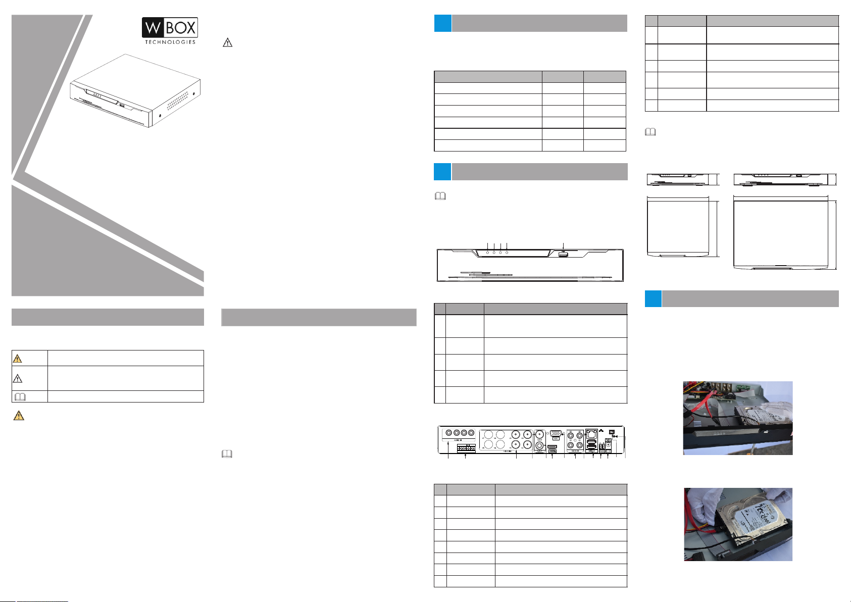
2.1 Device Ports
NOTE
Different device may have different ports, please refer to the
actual product.
Figure 2-1 Front panel
POWER
4
2
3
1
NET
ALARM
REC
5
Name
ID
LAN network
9
interface
10
USB
11
RS485
DC power
12
interface
Power switch
13
Ground screw
14
Description
RJ4 5 10 / 10 0/ 10 00 M bp s ad ap ti ve
Ethernet interface
Supports co nn ec ti on t o a US B mo us e an d
keyboard
RS485 port
Connected to an external power adapter
-(O pt io na l fo r di ff er en t DV R)
Saf e gr ou nd s cr ew o f th e de vi ce
2.2 Device Dimensions
NOTE
Diffe re nt d ev ic e may h av e di ff er en t di me ns io ns , pl ea se r ef er
to th e ac tu al p ro du ct .
Figure 2-3 Dimensions (Unit:mm)
43
255
230
350
44
297
Precautions
Fully understand this document before using this device, and
strictly observe rules in this document when using this device.
It al er ts y ou t o mod er at e da ng er s wh ic h, i f no t
WARNING
avoided, may cause minor or moderate injuries.
It al er ts y ou t o ri sk s. N eg le ct o f th es e ri sk s may
cause device damage, data loss, device
CAUTION
performance deterioration, or unpredictable results.
It provides additional information.
NOTE
WARNING
Strictly observe installation requirements when installing the
device. The manufacturer shall not be held responsible for
device damage caused by users' non-conformance to these
requirements.
Strictly conform to local electrical safety standards and use
power adapter s th at a re ma rk ed w it h th e LP S st an da rd w he n
installing and using this device. Otherwise, this device may be
damaged.
Use accessories delivered with this device. The voltage must
meet input voltage requirements for this device.
If this device is installed in places with unsteady voltage, ground
this device to discharge high energy such as electrical surges in
order to prevent the power supply from burning out.
Whe n th is d ev ic e is i n us e, e ns ur e th at n o wa te r or a ny l iq ui d
flows into the device. If water or liquid unexpectedly flows into
the device, immediately power off the device and disconnect all
cables (such as power cables and network cables) from this
device.
Do not fo cu s st ro ng l ig ht ( su ch a s li gh te d bu lb s or s un li gh t) o n
this de vi ce . Ot he rw is e, t he s er vi ce l if e of t he i ma ge s en so r may
be shortened.
If this device is installed in places where thunder and lightning
frequently occur, ground the device nearby to discharge high
Special Announcement
All complete products sold by the manufacturer are delivered
along with nameplates, quick setup guide and accessories after
strict inspection. The manufacturer shall not be held responsible
for counterfeit products.
The manufacturer will update this manual according to product
function enhancement or changes and regularly update the
software and hardware described in this manual. Update
information will be added to new versions of this manual without
prior notice.
This manual may contain misprints, technology information that
is not accurate enough, or product function and operation
description that is slightly inconsistent with the actual product,
the final interpretation of company is as a standard.
Thi s man ual is only for ref er en ce a nd d oe s no t en su re t ha t th e
information is totally consistent with the actual product. For
consistency, see the actual product.
NOTE
For mo re info rmati on, ple ase ref er to CD (included), wboxtech.com or
call W Box Tech Support 1-833-574-9124
Table 2-1 Front panel description
Port Name Description
ID
1
2
3
4
5
POWER
ALARM
REC
NET
USB
Power indicator, When DVR is operating, the
Power indicator is steady on. When DVR is
shut do wn , th e PW R in di ca to r is t ur ne d of f.
Alarm indicator
This indicator flashes when alarm is transmitted.
Record indicator
This indicator flashes when DVR is recording.
Net indicator
This indicator flashes when DVR record.
Supports co nn ec ti on t o an U SB m ou se a nd
keyboard
Figure 2-2 Rear panel
A5A6A7A8
4 3 2 1
C NO
ALARM I/O
5
3
1 2
4
Table 2-2 Rear panel description
Name
ID
1
AUDIO IN
ALARM I/O
2
3
VIDEO IN
CVBS
4
A-OUT
5
HDMI
6
7
VGA
AUDIO IN
8
Description
Audio Input
Alarm Input/Output
Video input
CVB S ou tp ut i nt er fa ce
Audio output
Video output interface
Video output interface
Audio Input
Device Installation
3
Depending on model, many W Box models already include a Hard
Drive installed. When a hard drive is not included or when adding
hard drives please take the following steps to install hard disks.
Ste p 1 Remove the s cr ew s fo r fi xi ng t he c ov er a nd t ak e do wn t he
cover.
Ste p 2 Take o ut t he s cr ew s an d fi x th e sc re ws o f ha rd d is k as
shown in fi gu re 3 -1 .
1
-
Figure3
8
11 12
13
9
14
10
Step
3 Ins er t th e ha rd d is k da ta c ab le a nd p ow er c ab le a s sh ow n in
figure 3-2.
6
7
Installing
hard disk
Figure3-2 Ins er t ha rd d is k da ta c ab le a nd p ow er c ab le
Ste p 4 Pu t on t he u pp er c ov er a nd f as te n th e fi xi ng s cr ew s.
Page 2
4
Device Operation
4.1 Startup
Bef or e st ar ti ng D VR , en su re t ha t th e DV R is c on ne ct ed t o a
power sup pl y pr op er ly a nd a m on it or i s co nn ec te d to t he H DM I or
VGA in te rf ac e of t he D VR c or re ct ly. D VR w il l enter the live video
interface and the power indica tor wi ll b e on , when DVR powers
on.
In some environments, if the power supply is abnormal,
the D VR may no t work pr operl y. In s evere c ases, t he DVR
CAUTION
may be damaged. In these environments, you are advised
to use regulated power supply.
4.2 Topo lo gy o f th e DV R
A free network includes other network devices in addition to IP
cameras and DVR. The topology of a free network can be
organiz ed f re el y so l on g as D VR a nd I P ca me ra s ca n
communicate with each other smoothly.
Figure 4-1 Topology of the DVR
IP camera
W Box VMS 1
W Box VMS
4.3 Power of f
choosing
shutdown
press in g th e po we r sw it ch t o po we r of f th e DV R if t he p ow er s wi tc h
exist i n re ar p an el .
Main Menu >System Settings >Advanced setting >
to po we r of f th e DV R, C li ck and choose shutdown or
Client
NOTE
If the DVR is shut down abnormally, it can automatically backup
video and resume previous working status after power failure.
Before replacing the hard disk, the power supply switch in the real
panel must be turned off.
Quick Configuration5
After access the DVR user page, right-click the user page,the
Main Menu displays. Main Menu comprises Camera, System
Settings, Log Center and Alarm Manager, as shown in figure 5-1.
Figure 5-1 Main menu
Picture param
Camera
Privacy area
Video lost
Privacy mask
Log Center
Motion detection
Alarm Manager
Encode param
OSD settings
Event
CCCllleeeaaarrr aaalllaaarrrmmm
System setting
Timeline
5.1 Camera
Camera comprises Camera Add or Delete, Picture Param,
Privacy area, Video lost, Privacy mask, Encode Param, OSD
setting and Motion Detection.
Add o r De le te : yo u ca n ad d a ca me ra t o a DV R ch an ne l or c li ck
Click Add to automatically search for and add cameras on the
network. Select a camera on a channel and click Clear to del et e
the selected camera, as shown in figure 5-2.
Picture Param: Based on scenarios, the brightness, contrast,
saturation and sharpness parameters can be automatically or
manually set for cameras on different channels. You can click
Apply to All to apply the parameter settings to all cameras as
shown in figure 5-3.
Encode Param: You can set resolution, image quality (Low,
Medium, Hig h, o r Hi gh es t) , f ra me r at e, B it ra te a nd B it ra te t yp e of
the camera on the current channel and stream.
Video lost: If the camera was disconnected, it will show video
lost.
Motion Detection: Press left button and drag the cursor to select
a detection area, and then double-click an area to delete the it.
Pri va cy a re a: P re ss l ef t bu tt on a nd d ra g th e cu rs or t o se le ct a
sheltering area, and then double-click an area to delete the
it.
OSD Settings: Custom the time and OSD, displayed in the live
video..
Menu
Lock
Protocol
lP
Name Account
Camera01
Only ca n setup a I PC that l ocked t o this de vice
The Loc ked IPC w ill be as signe d a chann el
Prior ity to co nnect t he Lock ed Came ra
Click r ight bu tton to e xit
Figure 5-2 Add or Delete
Add or d elete c amera
AHD/TVI
>
127.0.0.1
Password
-Only can s etup a PC t hat bin ded to th is NVR
admin
-IPC wil l bind to a c hanne l if it bin ded to th is NVR
-NVR wil l conne ct IPC th at bind ed to it
*****
Refresh
Click Add
lP
127.0.0.1
127.0.0.1
127.0.0.1
127.0.0.1
Clear
Lock
Status
Connected
Connected
Connected
Connected
OK
Figure 5-3 Picture Param
Menu
[1] IP Camera01
[2] IP C amera 02
[3] IP Camera03
[4] IP Camera04
Clic k right b utton t o exit
5.2 Setting
Setting includes Basic, Alarm Manager, Record, Output,
Network, Disk, Privilege Manage, Advanced setting and APP, as
shown in figure 5-4.
Bas ic : in cl ud es s ys te m an d ti me . You ca n vi ew t he D VR f ir mw ar e
version, compile time, product model, device name display and
language in system setting.
Alarm manager: You can enable surveillance to set the alarm
duration and enable alarm in to set the alarm type, name and
processing method.
Record: You can enable schedule record to set record schedule.
Output: Configure layout and CVBS output.
Network: You can set IPV4,port, DDNS and black list in network
setting.
Dis k: You c an v ie w th e di sk s iz e, t he d is k us ag e an d SN f or d is k.
Privilege manager: You can add, delete, edit user modify
Camera picture parameter
Wher e to inst all thi s camer a
Brightness
50
Saturation
50
Contrast
50
Sharpness
48
Default
Apply to all
OK
passw or d an d se t E- ma il f or p as sw or d re tu rn f or D VR .
Advanced setting: You can reset, reboot and shutdown DVR in
advanced setting.
APP : Ob ta in t he Q R co de f or a pp .
Figure 5-4 System Setting
System Setting
Basic
Alarm Manager
Surveillance
Alarm In
Record
Output
Network
Disk
Privilege Manager
Advanced Setting
App
Cli ck righ t butto n to exit
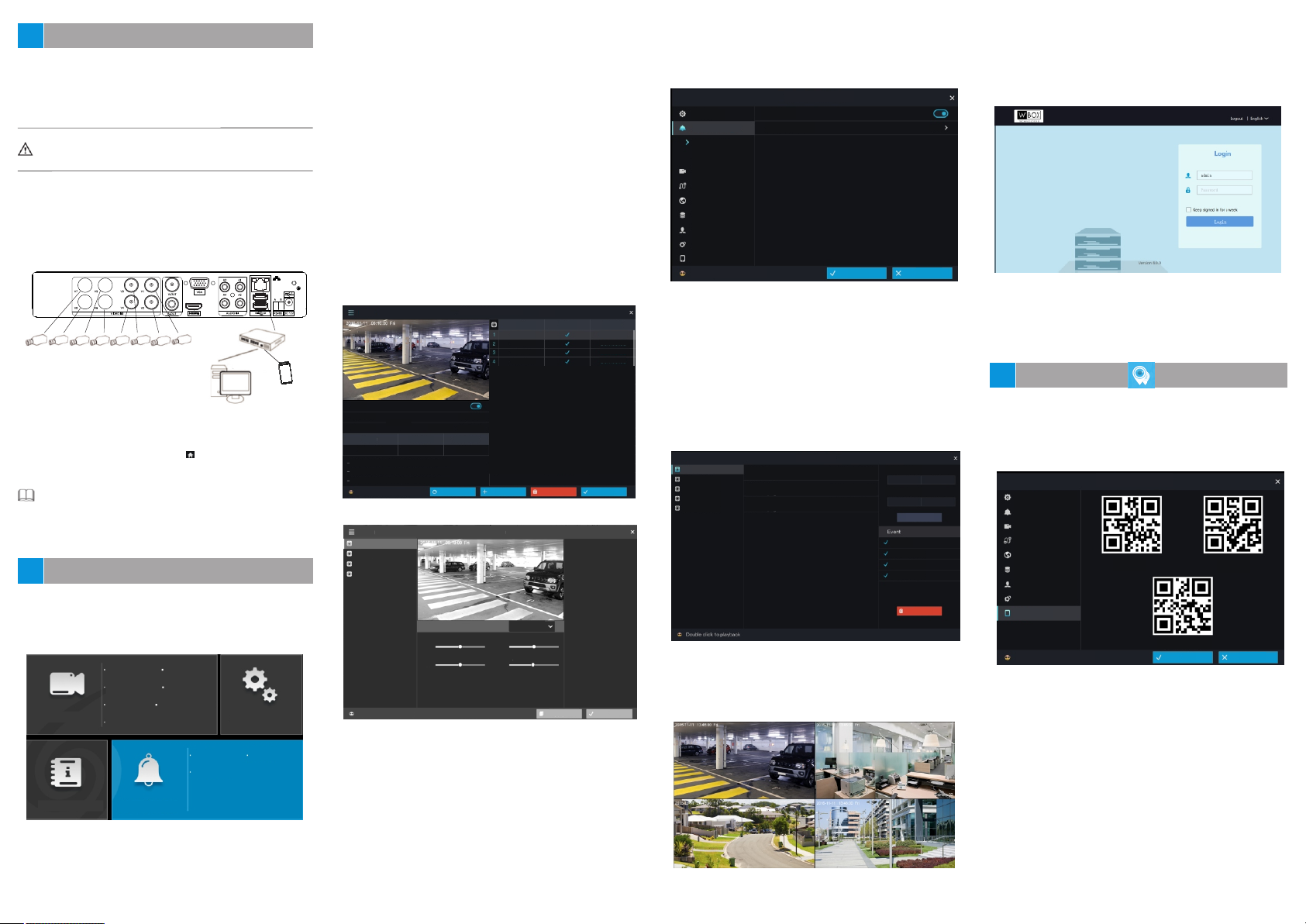
5.3 Alarm
Alarm comprises Event Center, Time Setting and Event Type
Selection as shown in figure 5-5.
Eve nt C en te r: You c an v ie w th e al ar m ev en t li st o f a ca me ra , an d
play back event videos by double-click the event records in the
event center.
Sta rt Ti me & E nd Ti me : You ca n cl ic k th e da te a nd t im e in pu t
boxes to display the date and time drop-down list boxes, where
you can s et t he s ta rt a nd e nd t im e of a la rm s.
Event: comprises multiple alarm modes such as Alarm in,
Motion alarm, Tamper alarm and disconnected. You can select
an alarm type based on requirements.
Enable
Alarm duration
10s
OK
Canel
Figure 5-5 Alarm
All
[1] Camera01
[2] Camera02
[3] Camera03
[4] Camera04
5.4 Live Video
Inp ut t he u se r na me a nd p as sw or d on t he l og in p ag e, t he n cl ic k
Login to access the live video page, as shown in fig ur e 5- 6.
System
No cable plugin
System
No cable plugin
System
No cable plugin
Event Center
2017/08/07 03:14:47 Mon
2017/08/07 01:26:32 Mon
2017/08/07 00:58:20 Mon
Start Time
2017/08/06
EndTime
2017/08/07
Alarm I n
Motion Alarm
Tamper Alarm
Disconnected
15:24:04
15:24:04
Refresh
Clear
Figure 5-6 Live video
5.5 W eb
Thi s DV R ca n be a cc es se d th ro ug h We b. O pe n th e we b br ow se r
such as Foxfire, input the device IP address (192.168.0.121 by
default) in the address box, and press Enter. Th e lo gi n pa ge i s
displayed. as shown in figure 5-7.
Figure 5-7 Login
5.6 Default Username/Password
The default user name is admin. The default password is admin. You
are required to change the password when you log in the system for first
time to ensure system security.
Mobile client
6
Sca n th e And ro id o r IO S QR c od e on t he
> APP b y us in g a br ow se r or o th er s of tw ar e th at
Settings >
supports QR code scanning on a mobile device, download and
install the client based on the prompt. Or search for “W Box VMS
1" in APP Sto re o r Go og le P la y, do wn lo ad a nd i ns ta ll t he c li en t.
Main Menu >System
Figure 6-1 APP
System Setting
Basic
Alarm Manager
Record
Output
Network
Disk
Privilege Manager
Advanced setting
App
Click right button to exit
If you have any questions, please call W Box Tech Support
1-833-574-9124 for assistance.
iOS
Android
rj_default_sn
OK Cancel
 Loading...