

Page 1
BOX
0E-41TP1UN
0E-82TP1UN
0E-162TP15UN
FOR TECHNICAL SUPPORT: 1-888-668-8808
T E
C H N O L O G
I E S
Page 2

Contents
Contents ..................................................................................................................................................................................... 2
Warranty .................................................................................................................................................................................... 3
Regulatory Information .............................................................................................................................................................. 8
Preventive and Cautionary Tips ................................................................................................................................................. 9
Trademarks and Registered Trademarks ................................................................................................................................... 9
Appearance Description ........................................................................................................................................................... 10
Getting Started ......................................................................................................................................................................... 14
Live View .................................................................................................................................................................................. 15
Record ...................................................................................................................................................................................... 20
Playback ................................................................................................................................................................................... 21
Backup ...................................................................................................................................................................................... 23
Accessing via Web Browser ...................................................................................................................................................... 26
Specifications ........................................................................................................................................................................... 28
2
Page 3

The content in this manual is subject to change without notice. Updates will be added to future versions of this manual.
Warranty
Product Categories
Warranty Period
Soundbars
12 months
Televisions
12 Months
Intrusion Wireless Communication
Accessories
12 Months
Analog Cameras
24 months
CCTV Power Supplies
24 months
In Ceiling Speakers
24 months
Magnetic Locks
24 Months
Request to Exit Devices
24 Months
Surge Protection
24 months
UPS (uninterruptible power supplies)
24 months
Volume Controls
24 months
Intrusion Audio Devices
30 months
Monitors
30 months
Video Baluns
30 months
DISCLAIMER STATEMENT
“Underwriters Laboratories Inc. (“UL”) has not tested the performance or reliability of the security or signaling aspects of
this product. UL has only tested for fire, shock or casualty hazards as outlined in UL’s Standard(s) for Safety, UL60950-
1. UL Certification does not cover the performance or reliability of the security or signaling aspects of this product. UL
MAKES NO REPRESENTATIONS, WARRANTIES OR CERTIFICATIONS WHATSOEVER REGARDING THE PERFORMANCE OR
RELIABILITY OF ANY SECURITY OR SIGNALING RELATED FUNCTIONS OF THIS PRODUCT.
1. Limited Warranty
a. General
Subject to the terms and conditions of this Limited Warranty, from the date of sale through the period of time for product
categories specified in Section 1(b), ADI warrants its W Box Technologies products to be free from defects in materials and
workmanship under normal use and service, normal wear and tear excepted. Except as required by law, this Limited
Warranty is only made to Buyer and may not be transferred to any third party.
ADI shall have no obligation under this Limited Warranty or otherwise if:
(i) The product is improperly installed, applied or maintained;
(ii) The product is installed outside of stated operating parameters, altered, or improperly services or repaired;
(iii) Damage is caused by outside natural occurrences, such as lightning, power surges, fire, floods, acts of nature, or
the like.
(iv) Defects resulting from unauthorized modification, misuse, vandalism, or other causes
unrelated to defective materials or workmanship, or failures related to batteries of any type used in connection with the
products sold hereunder.
ADI only warrants those products branded as W Box Technologies products and sold by ADI. Any other products branded
by third parties are warranted by the third party manufacturer for a period as defined by the third party manufacturer,
and ADI assigns to Buyer those warranties and only those warranties extended by such third party manufacturers or
vendors for non-ADI branded products. ADI does not itself warrant any non-ADI branded product and sells only on an as is
basis in accordance with ADI’s terms and conditions of sale.
b. Specific Warranties for product categories are as follows:
3
Page 4

DVR's, NVR's
60 Months
IP Cameras
60 Months
Magnetic Locks
60 Months
Racks
60 months
TV Mounts
60 months
PIR’s
84 months
Analog Cables
Limited Lifetime
B Connectors
Limited Lifetime
Bus Terminals
Limited Lifetime
Extension Cords
Limited Lifetime
HDMI Cables
Limited Lifetime
Jacks, Cords and Intrusion
Communication Accessories
Limited Lifetime
Patch Cables
Limited Lifetime
Raceway Conduit
Limited Lifetime
Wire Ties
Limited Lifetime
2. EXCLUSION OF WARRANTIES, LIMITATION OF LIABILITY
THERE ARE NO WARRANTIES OR CONDITIONS, EXPRESS OR IMPLIED, OF MERCHANTABILITY, OR FITNESS FOR A
PARTICULAR PURPOSE OR OTHERWISE, WHICH EXTEND BEYOND THE DESCRIPTION ON THE FACE HEREOF. TO THE
FULLEST EXTENT PERMITTED BY LAW, IN NO CASE SHALL ADI BE LIABLE TO ANYONE FOR ANY (I) CONSEQUENTIAL,
INCIDENTAL, INDIRECT, SPECIAL, OR PUNITIVE DAMAGES ARISING OUT OF OR RELATING IN ANY WAY TO THE PRODUCT
AND.OR FOR BREACH OF THIS OR ANY OTHER WARRANTY OR CONDITION, EXPRESS OR IMPLIED, OR UPON ANY OTHER
BASIS OF LIABILITY WHATSOEVER, EVEN IF THE LOSS OR DAMAGE IS CAUSED BY ADI’S OWN NEGLIGENCE OR FAULT AND
EVEN IF ADI HAS BEEN ADVISED OF THE POSSIBILITY OF SUCH LOSSES OR DAMAGES. Any product description (whether in
writing or made orally by ADI or ADI’s agents), specifications, samples, models, bulletin, drawings, diagrams, engineering
sheets, or similar materials used in connection with the Buyer’s order are for the sole purpose of identifying ADI’s
products and shall not be construed as an express warranty or condition. Any suggestions by ADI or ADI’s agents
regarding use, applications or suitability of the products shall not be construed as an express warranty or condition unless
confirmed to be such in writing by ADI. ADI does not represent that the products it sells may not be compromised or
circumvented; that the products will prevent any personal injury or property loss by burglary, robbery, fire or otherwise,
or that the products will in all cases provide adequate warning or protection. Buyer understands and will cause its
customer to understand that a properly installed and maintained product is not insurance or guarantee that such will not
cause or lead to personal injury or property loss. CONSEQUENTLY ADI SHALL HAVE NO LIABILITY FOR ANY PERSONAL
INJURY, PROPERTY DAMAGE OR OTHER LOSS BASED ON ANY CLAIM AT ALL INCLUDING A CLAIM THAT THE PRODUCT
FAILED TO GIVE WARNING. However, if ADI is held liable whether directly or indirectly for any loss or damage with
respect to the products it sells, regardless of cause or origin, its maximum liability shall not in any case exceed the
purchase price of the product, which shall be fixed as liquidated damages and not as a penalty and shall be the complete
and exclusive remedy against ADI.
3. Limitation on Liability to Buyer’s Customers.
Buyer agrees to limit liability to its customers to the fullest extent permitted by law. Buyer acknowledges that ADI shall
only be deemed to give consumers of its products such statutory warranties as may be required by law and at no time
shall Buyer represent to its customers and/or users of ADI products that ADI provides any additional warranties. By
accepting the products, to the fullest extent permitted by law, Buyer assumes all liability for, and agrees to indemnity and
hold ADI harmless against and defend ADI from, any and all suits, claims, demands, causes of action and judgments
relating to damages, whether for personal injury or to personal property, suffered by any person, firm, corporation or
business association, including but not limited to, Buyer’s customers and/or users of the products because of any failure of
the products to detect and/or warn of the danger for which the goods were designed or any other failure of the products
whether or not such damages are caused or contributed to by the sold or joint concurring negligence or fault of ADI.
4
Page 5

4. Returns
Subject to the terms and conditions listed below, during the applicable warranty period, ADI will replace Product or
provide a credit at purchase at its sole option free of charge any defective products returned prepaid. Any obligations of
ADI to replace Limited Lifetime warranty products pursuant to this warranty which result from defect are limited to the
availability of replacement product. ADI reserves the right to replace any such products with the then currently available
products, or provide a credit in its sole discretion. In the event Buyer has a problem with any ADI product, please call your
local ADI branch for return instructions:
For US call 1-800-233-6261
For Canada call 877-234-7378
For Puerto Rico call 787-793-8830
Be sure to have the model number and the nature of the problem available. In the event of replacement, the return
product will be credited to Buyer’s account and a new invoice issued for the replacement item. ADI reserves the right to
issue a credit only in lieu of replacement.
If any W Box Technologies product is found to be in good working order or such product’s inability to function properly is a
result of user damage or abuse, the product will be returned to Buyer in the same condition as received and Buyer shall be
responsible for any return freight changes.
5. Governing Law
The laws of State of New York apply to this Limited Warranty.
6. Miscellaneous
Where any term of this Limited Warranty is prohibited by such laws, it shall be null and void, but the remainder of the
Limited Warranty shall remain in full force and effect.
1. Garantie limitée
a. Généralités
Sous réserve des modalités de la présente garantie limitée, à compter de la date de vente et pendant la période de
garantie applicable aux catégories de produits précisée au paragraphe 1b), ADI garantit que ses produits W Box
Technologies sont libres de tout vice de matériaux et de fabrication dans des conditions d’utilisation et d’entretien
normales, sauf l’usure normale. Sauf si les lois l’exigent, la présente garantie limitée est offerte uniquement à
l’acheteur et ne peut être transférée à un tiers.
ADI n’a aucune obligation aux termes de la présente garantie limitée ou autrement dans les circonstances suivantes :
i) le produit est mal installé, appliqué ou entretenu;
ii) le produit est installé de manière non conforme aux paramètres d’exploitation indiqués, modifié ou mal entretenu
ou réparé;
iii) le produit est endommagé par des phénomènes naturels extérieurs comme la foudre, une surcharge, un incendie,
une inondation, une force majeure ou un phénomène similaire;
iv) les défectuosités du produit résultent d’une modification non autorisée, d’une mauvaise utilisation, d’un acte de
vandalisme ou d’autres causes non liés aux vices de matériaux ou de fabrication, ou à une défaillance des piles de
quelque type que ce soit utilisées avec les produits vendus aux termes des présentes.
ADI ne garantit que les produits portant la marque W Box Technologies qu’elle vend. Les autres produits portant une
marque de tiers sont garantis par le fabricant tiers pendant une période définie par ce dernier, et ADI cède à
l’acheteur ces garanties et uniquement les garanties offertes par ces fabricants tiers ou vendeurs à l’égard de produits
ne portant pas ses marques. ADI ne garantit pas de produits ne portant pas ses marques et vend ces produits tels
5
Page 6

quels, conformément à ses modalités de vente.
Catégories de produits
Période de la garantie
Téléviseurs
12 mois
Accessoires de communication d’intrusion sans fil
12 mois
Barres de son
12 mois
UPS (systèmes d’alimentation sans coupure)
24 mois
Caméras analogiques
24 mois
Blocs d’alimentation CCTV
24 mois
Contrôles du volume
24 mois
Protection contre les surcharges
24 mois
Haut-parleurs pour le plafond
24 mois
Modules de requête de sortie
24 mois
Mise à jour des serrures magnétiques
24 mois
Écrans
30 mois
Balluns vidéo
30 mois
Système d’alarme anti-intrusion
30 mois
Serrures magnétiques
36 mois
Bâtis
60 mois
Supports de télévision
60 mois
Caméras IP
60 mois
DVRs, NVR's
60 mois
Détecteurs de mouvement infrarouge
84 mois
Attaches pour câbles
À vie limitée
Câbles analogiques
À vie limitée
Câbles de raccordement
À vie limitée
Bornes de bus
À vie limitée
Connecteurs B
À vie limitée
Cordes d’extension
À vie limitée
Contacts magnétiques
À vie limitée
Bloc modulaire, câbles et accessoires de
communication
À vie limitée
Conduits cache-fil
À vie limitée
Câbles HDMI
À vie limitée
b. Les garanties particulières applicables aux catégories de produits sont les suivantes :
2. EXCLUSION DE GARANTIES ET LIMITATION DE RESPONSABILITÉ
IL N’EXISTE AUCUNE GARANTIE OU CONDITION, EXPRESSE OU IMPLICITE, DE QUALITÉ MARCHANDE, D’ADAPTATION À
UNE FIN PARTICULIÈRE OU AUTRE QUI DÉPASSE LE CADRE DE LA DESCRIPTION FOURNIE AU RECTO DES PRÉSENTES.
DANS LA PLEINE MESURE PERMISE PAR LA LOI, ADI NE SAURAIT EN AUCUN CAS ÊTRE TENUE RESPONSABLE ENVERS
QUICONQUE DES DOMMAGES CONSÉCUTIFS, INDIRECTS, SPÉCIAUX OU PUNITIFS DÉCOULANT DU PRODUIT OU LIÉS À
CELUI-CI DE QUELQUE FAÇON QUE CE SOIT ET/OU DU NON-RESPECT DE LA PRÉSENTE GARANTIE OU DE TOUTE AUTRE
GARANTIE OU CONDITION, EXPRESSE OU IMPLICITE, OU DE TOUTE AUTRE RÉCLAMATION FONDÉE SUR LA
RESPONSABILITÉ, MÊME SI LA PERTE OU LES DOMMAGES SONT CAUSÉS PAR LA NÉGLIGENCE OU LA FAUTE D’ADI ET
MÊME SI CETTE DERNIÈRE A ÉTÉ AVISÉE DE LA POSSIBILITÉ QUE DE TELLES PERTES OU DE TELS DOMMAGES
SURVIENNENT. Les descriptions de produits (fournies par écrit ou verbalement par ADI ou ses mandataires),
caractéristiques techniques, échantillons, modèles, bulletins, dessins, diagrammes, esquisses techniques ou
documents similaires utilisés par l’acheteur pour passer une commande visent uniquement à décrire les produits
d’ADI et ne doivent pas être interprétés comme des garanties ou conditions expresses. Les suggestions faites par ADI
6
Page 7

ou ses mandataires au sujet de l’utilisation, de l’application ou du caractère approprié des produits ne doivent pas
être interprétées comme des garanties ou conditions expresses, sauf si ADI confirme par écrit qu’il s’agit de garanties
ou de conditions expresses. ADI ne garantit pas qu’il n’y aura aucune atteinte à l’intégrité des produits qu’elle vend ou
que les produits qu’elle vend ne seront pas contournés, qu’ils préviendront les blessures ou les pertes matérielles en
cas de cambriolage, de vol, d’incendie ou autrement ou qu’ils constitueront dans tous les cas une protection ou un
avertissement approprié. L’acheteur comprend qu’un produit dûment installé et entretenu permet uniquement de
réduire le risque de cambriolage, de vol ou d’incendie sans avertissement, mais qu’il ne constitue pas une assurance
ou une garantie qu’un tel événement ne se produira pas ou qu’il n’entraînera pas des blessures ou des pertes
matérielles. PAR CONSÉQUENT, ADI NE SAURAIT ÊTRE TENUE RESPONSABLE DES BLESSURES, DES DOMMAGES
MATÉRIELS OU D’AUTRES PERTES FAISANT L’OBJET D’UNE RÉCLAMATION, Y COMPRIS UNE RÉCLAMATION SELON
LAQUELLE LE PRODUIT N’AURAIT PAS DONNÉ DE SIGNAL D’AVERTISSEMENT. Toutefois, si ADI est tenue responsable,
directement ou indirectement, de pertes ou de dommages à l’égard des produits qu’elle vend, quelle qu’en soit la
cause ou l’origine, sa responsabilité n’excédera en aucun cas le prix d’achat du produit, dont le remboursement sera
exigé à titre de dommages-intérêts extrajudiciaires et non d’amende, et il s’agira du recours exclusif et intégral
pouvant être exercé contre ADI.
3. Limitation de la responsabilité envers les clients de l’acheteur.
L’acheteur s’engage à limiter la responsabilité envers ses clients dans la pleine mesure permise par la loi. L’acheteur
reconnaît qu’ADI ne sera réputée avoir fourni aux consommateurs de ses produits que les garanties qui sont exigées
par la loi. L’acheteur ne doit en aucun cas déclarer à ses clients et/ou aux utilisateurs des produits d’ADI que cette
dernière offre d’autres garanties. Par l’acceptation des produits, l’acheteur assume, dans la pleine mesure permise par
la loi, la pleine responsabilité à l’égard de toutes les poursuites, réclamations, mises en demeure et causes d’action et
à l’égard de tous les jugements se rapportant à des dommages-intérêts, que ce soit pour des préjudices personnels ou
des dommages matériels, subis par une personne, une firme, une société ou une association commerciale, y compris
les clients de l’acheteur et/ou les utilisateurs des produits, en raison de toute omission de la part des produits de
déceler le danger pour la détection duquel ils sont conçus et/ou de donner l’alerte de ce danger ou un avertissement
de toute autre défaillance des produits, que ces dommages aient été causés par la négligence dont ADI est l’auteur ou
le coauteur, et il tiendra ADI à couvert à cet égard et prendra fait et cause pour lui.
4. Retours
Sous réserve des modalités énumérées ci-après, durant la période de garantie applicable, ADI remplacera le produit
ou donnera une note de crédit à l’achat, à son gré et sans frais, à l’égard de tout produit défectueux qui lui est
retourné. L’obligation qui incombe à ADI de remplacer le produit visé par une garantie à vie limitée aux termes de la
garantie en question si celui-ci est défectueux se limite à la disponibilité d’un produit de remplacement. ADI se réserve
le droit de remplacer un produit défectueux par le produit qui est disponible à ce moment-là, ou de donner une note
de crédit, à son gré. Si l’acheteur a un problème avec un produit d’ADI, il doit appeler sa succursale ADI locale pour
connaître la marche à suivre pour retourner le produit.
Aux États-Unis, composer le 1 800 233-6261
Au Canada, composer le 877 234-7378
À Porto Rico, composer le 787 793-8830
L’acheteur doit avoir en main le numéro du modèle et décrire la nature du problème. En cas de remplacement, le prix
du produit retourné sera porté au crédit du compte de l’acheteur et une nouvelle facture sera établie pour le produit
de remplacement. ADI se réserve le droit de donner une note de crédit plutôt que de remplacer le produit.
Si l’on établit que le produit W Box Technologies n’est pas défectueux ou que son mauvais fonctionnement résulte
d’une utilisation abusive ou de dommages causés par l’utilisateur, le produit sera retourné à l’acheteur dans le même
état que celui dans lequel il a été reçu et l’acheteur devra acquitter les frais de transport.
7
Page 8

5. Lois applicables
Regulatory Information
Les lois de l’État de New York s’appliquent à la présente garantie limitée.
6. Modalités diverses
Si une modalité de la présente garantie limitée est interdite par ces lois, elle sera nulle, mais le reste de la présente
garantie limitée demeurera pleinement en vigueur.
FCC Information
FCC compliance: This equipment has been tested and found to comply with the limits for a digital device, pursuant to part
15 of the FCC Rules. These limits are designed to provide reasonable protection against harmful interference when the
equipment is operated in a commercial environment. This equipment generates, uses, and can radiate radio frequency
energy and, if not installed and used in accordance with the instruction manual, may cause harmful interference to radio
communications. Operation of this equipment in a residential area is likely to cause harmful interference in which case the
users will be required to correct the interference at their own expense.
FCC Conditions
This device complies with part 15 of the FCC Rules. Operation is subject to the following two conditions:
1. This device may not cause harmful interference.
2. This device must accept any interference received, including interference that may cause undesired operation
EU Conformity Statement
This product and - if applicable - the supplied accessories too are marked with "CE" and comply therefore with
the applicable harmonized European standards listed under the Low Voltage Directive 2006/95/EC, the EMC
Directive 2004/108/EC, the RoHS Directive 2011/65/EU.
Municipal waste in the European Union. For proper recycling, return this product to your local supplier upon the
purchase of equivalent 2012/19/EU (WEEE directive): Products marked with this symbol cannot be disposed of
as unsorted municipal waste in the European Union. For proper recycling, return this product to your local
supplier upon the purchase of equivalent new equipment, or dispose of it at designated collection points. For more
information, see: www.recyclethis.info.
2006/66/EC (battery directive): This product contains a battery that cannot be disposed of as unsorted municipal
waste in the European Union. See the product documentation for specific battery information. The battery is
marked with this symbol, which may include lettering to indicate cadmium (Cd), lead (Pb), or mercury (Hg). For
proper recycling, return the battery to your supplier or to a designated collection point. For more information,
see: www.recyclethis.info.
8
Page 9

Preventive and Cautionary Tips
Trademarks and Registered Trademarks
Before connecting and operating your device, please be advised of the following tips:
• Ensure unit is installed in a well-ventilated, dust-free environment.
• Unit is designed for indoor use only.
• Keep all liquids away from the device.
• Ensure environmental conditions meet factory specifications.
• Ensure unit is properly secured to a rack or shelf. Major shocks or jolts to the unit as a result of dropping it may
cause damage to the sensitive electronics within the unit.
• Use the device in conjunction with an UPS if possible.
• Power down the unit before connecting and disconnecting accessories and peripherals.
• A factory recommended HDD should be used for this device.
• Improper use or replacement of the battery may result in hazard of explosion. Replace with the same or
equivalent type only. Dispose of used batteries according to the instructions provided by the battery manufacturer.
Windows and Windows mark are trademarks or registered trademarks of Microsoft Corporation in the United States
and/or other countries.
HDMI, HDMI mark and High-Definition Multimedia Interface are trademarks or registered trademarks of HDMI Licensing
LLC.
The products contained in this manual are authorized by HDMI Licensing LLC with the use right of the HDMI technology.
VGA is the trademark of IBM.
UPnPTM is a certification mark of the UPnP
Other names of companies and product contained in this manual may be trademarks or registered trademarks of their
respective owners.
TM
Implementers Corporation.
9
Page 10

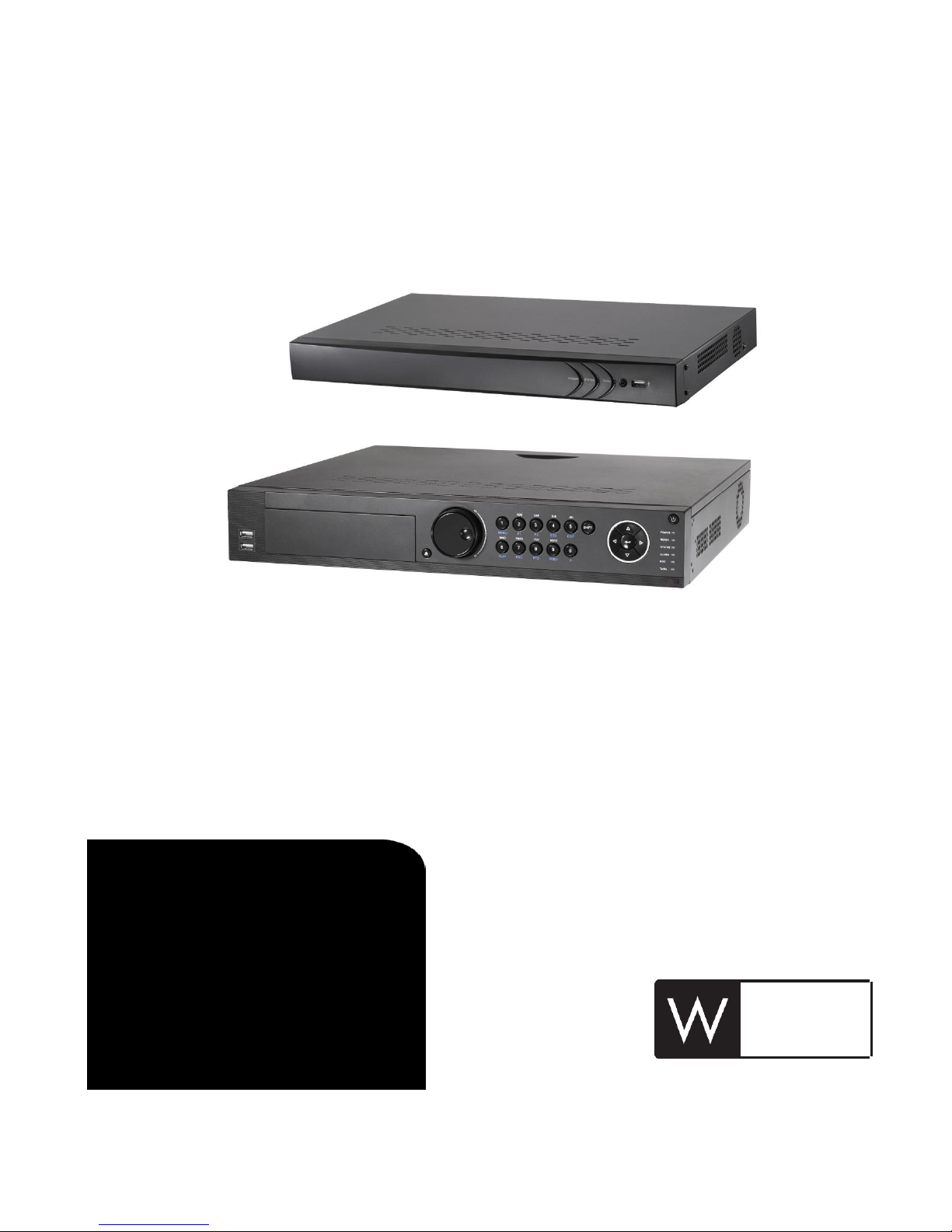
Appearance Description
No.
Name
Description
1
Status
Indicator
Power
Power indicator turns yellow when system is running.
Status
Status indicator blinks red when data is being read from
or written to HDD.
Tx/Rx
Tx/Rx indictor blinks yellow when network connection is
functioning properly.
2
USB Interface
Universal Serial Bus (USB) ports for additional devices
such as USB mouse and USB Hard Disk Drive (HDD).
No.
Item
Description
1
Power Supply
48V DC power supply for 0E-41TP1UN and AC 100~240V
for 0E-82TP1UN/0E-162TP15UN.
2
Audio In
RCA connector for audio input.
3
HDMI Interface
HDMI video output connector.
4
LAN Network
Interface
1 10 /100 /1000 Mbps self-adaptive Ethernet interface
5
Audio Out
RCA connector for audio output.
6
VGA Interface
DB9 connector for VGA output. Display local video output
and menu.
7
USB Interface
Universal Serial Bus (USB) ports for additional devices such
as USB mouse and USB Hard Disk Drive (HDD).
8
Ground
Ground (needs to be connected when NVR starts up).
9
Power Switch
Switch for turning on/off the device.
10
Network Interfaces
with PoE function
Network interfaces for the cameras and to provide power
over Ethernet.
10
Page 11

No.
Name
Function Description
1
Status
Indicators
POWER
Turns green when NVR is powered up.
READY
The LED is green when the device is running normally.
STATUS
The light is green when the IR remote control is
enabled;
The light is red when the function of the composite
keys (SHIFT) are used;
The light is out when none of the above condition is
met.
ALARM
The light is red when there is an alarm occurring.
HDD
Blinks red when HDD is reading/writing.
Tx/Rx
Blinks green when network connection is functioning
normally. 2 DVD-R/W
Slot for DVD-R/W.
3
Control
Buttons
DIRECTION
In menu mode, the direction buttons are used to
navigate between different fields and items and
select setting parameters.
In playback mode, the Up and Down buttons are used
to speed up and slow down record playing, and the
Left and Right buttons are used to move the
recording 30s forwards or backwards.
In the image setting interface, the up and down
button can adjust the level bar of the image
parameters.
In live view mode, these buttons can be used to
switch channels.
ENTER
The Enter button is used to confirm selection in menu
mode; or used to check checkbox fields and ON/OFF
switch.
In playback mode, it can be used to play or pause the
video.
In single-frame play mode, pressing the Enter button
will play the video by a single frame.
In auto sequence view mode, the buttons can be
used to pause or resume auto sequence.
4
Composite
Keys
SHIFT
Switch between the numeric or letter input and
functions of the composite keys. (Input letter or
numbers when the light is out; Realize functions
when the light is red.)
1/MENU
Enter numeral “1”;
11
Page 12

No.
Name
Function Description
Access the main menu interface.
2/ABC/F1
Enter numeral “2”;
Enter letters “ABC”;
The F1 button when used in a list field will select all
items in the list.
In PTZ Control mode, it will turn on/off PTZ light and
when the image is zoomed in, the key is used to zoom
out.
3/DEF/F2
Enter numeral “3”;
Enter letters “DEF”;
The F2 button is used to change the tab pages.
In PTZ control mode, it zooms in the image.
4/GHI/ESC
Enter numeral “4”;
Enter letters “GHI”;
Exit and back to the previous menu.
5/JKL/EDIT
Enter numeral “5”;
Enter letters “JKL”;
Delete characters before cursor;
Check the checkbox and select the ON/OFF switch;
Start/stop record clipping in playback.
6/MNO/PLAY
Enter numeral “6”;
Enter letters “MNO”;
Playback, for direct access to playback interface.
7/PQRS/REC
Enter numeral “7”;
Enter letters “PQRS”;
Open the manual record interface.
8/TUV/PTZ
Enter numeral “8”;
Enter letters “TUV”;
Access PTZ control interface.
9/WXYZ/PR
EV
Enter numeral “9”;
Enter letters “WXYZ”;
Multi-channel display in live view.
0/A
Enter numeral “0”;
Shift the input methods in the editing text field.
(Upper and lowercase, alphabet, symbols or numeric
input).
Double press the button to switch the main and
auxiliary output.
5
JOG SHUTTLE Control
Move the active selection in a menu. It will move the
selection up and down.
In Live View mode, it can be used to cycle through
different channels.
In the Playback mode, it can be used to jump 30s
forward/backward in video files.
In PTZ control mode, it can control the movement of
the PTZ camera.
6
POWER ON/OFF
Power on/off switch.
12
Page 13

No.
Name
Function Description
7
USB Interfaces
Universal Serial Bus (USB) ports for additional devices
such as USB mouse and USB Hard Disk Drive (HDD).
No.
Item
Description
1
LAN Interface
Network interface.
2
AUDIO OUT
RCA connector for audio output.
3
LINE IN
RCA connector for audio input.
4
HDMI
HDMI video output connector.
5
USB 3.0 interface
Universal Serial Bus (USB) ports for additional devices
such as USB mouse and USB Hard Disk Drive (HDD).
6
RS-232 Interface
Connector for RS-232 devices.
7
VGA
DB9 connector for VGA output. Display local video output
and menu.
8
RS-485 Interface
Half-duplex connector for RS-485 devices.
9
ALARM IN
Connector for alarm input.
ALARM OUT
Connector for alarm output.
10
GROUND
Ground (needs to be connected when NVR starts up).
11
AC 100V ~ 240V
100V ~ 240V AC power supply.
12
Power Switch
Switch for turning on/off the device.
13
Network Interfaces
with PoE function
Network interfaces for the cameras and to provide power
over Ethernet.
13
Page 14

Getting Started
The default user name is admin and password is wbox123.
This product has default user name and password credentials for first time access. You must change these
default credentials to protect against unauthorized access to the product.
Starting Up and Shutting Down the NVR
Proper startup and shutdown procedures are crucial to expanding the life of the NVR.
Before you start:
Check that the voltage of the extra power supply is the same with the NVR’s requirement, and the ground connection is
working properly.
Starting up the NVR
Steps:
1. Check the power supply is plugged into an electrical outlet. It is HIGHLY recommended that an Uninterruptible Power
Supply (UPS) be used in conjunction with the device.
2. Turn on the power switch on the rear panel, and the Power indicator LED should turn on indicating that the unit
begins to start up.
3. After startup, the Power indicator LED remains on.
Shutting down the NVR
Steps:
1. Enter the Shutdown menu.
Menu > Shutdown
2. Select the Shutdown button.
3. Click the Yes button.
4. Turn off the power switch on the rear panel when the note appears.
Menu Operation
After entering the local operation interface of the device, you can right click on the screen to access the right-click menu
and select the Menu to enter the menu of the device. Refer to the following figure:
14
Page 15

The menu structure is shown as below:
Menu
Export Manual HDD Camera
Maintenance
Shutdown
Record
Configuration
Playback
Normal Record General Schedule Camera General
System Info
Logout
Event Advanced Parameters OSD
Network
Log
Information
Shutdown
Advanced
Image
Import/Export
Reboot
Holiday PTZ
Upgrade
Motion
Live View Default
Exceptions
Net Detect
User
HDD Detect
Alarm
Alarm
RS-232
Normal
Event
Tag
Smart
External
File
Live View
Live view shows you the video image getting from each camera in real time. The NVR will automatically enter Live View
mode when powered on. It is also at the very top of the menu hierarchy, thus hitting the ESC many times (depending on
which menu you’re on) will bring you to the Live View mode.
Live View Icons
15
Page 16

In the live view mode, there are icons at the right top of the screen for each channel, showing the status of the record and
Icons
Description
Alarm (video loss, tampering, motion detection or sensor alarm)
Record (manual record, schedule record, motion detection or alarm
triggered record)
Alarm & Record
Event/Exception
Icons
Description
Icons
Description
Icons
Description
/
Enable Manual
Record
Instant
Playback
/
Mute/Audio
on
PTZ Control
Digital Zoom
Image
Settings
Close
alarm in the channel, so that you can know whether the channel is recorded, or whether there are alarms occur as soon as
possible.
On the screen of each channel, there is a quick setting toolbar which shows when you point the mouse to the bottom of
the screen.
Operations in Live View Mode
In live view mode, there are many functions provided. The functions are listed below.
• Single Screen: showing only one screen on the monitor.
• Multi-screen: showing multiple screens on the monitor simultaneously.
• Auto-switch: the screen is auto switched to the next one. And you must set the dwell time for each screen on the
configuration menu before enabling the auto-switch.
Menu>Configuration>Live View>Dwell Time.
• Start Recording: continuous record and motion detection record are supported.
• Output Mode: select the output mode to Standard, Bright, Gentle or Vivid.
• Add IP Camera: the shortcut to the IP camera management interface.
• Playback: playback the recorded videos for current day.
Adjusting Live View Settings
Live View settings can be customized according to different needs. You can configure the output interface, dwell time for
screen to be shown, mute or turning on the audio, the screen number for each channel, etc.
Steps:
1. Enter the Live View Settings interface.
Menu> Configuration> Live View
16
Page 17

The settings available in this menu include:
• Video Output Interface: Designates the output to configure the settings for. Outputs include HDMI/VGA and CVBS
(depends on the model).
• Live View Mode: Designates the display mode to be used for Live View.
• Dwell Time: The time in seconds to dwell between switching of channels when enabling auto-switch in Live View.
• Enable Audio Output: Enables/disables audio output for the selected camera in the live view mode.
• Event Output: Designates the output to show event video; if available, you can select a different video output
interface from the Video Output Interface when an event occurs.
• Full Screen Monitoring Dwell Time: The time in seconds to show alarm event screen.
2. Set the camera order.
1) Select View tab.
2) Select an output interface and select a screen layout.
3) Click to select a screen in the right region and double-click to select a channel in the left region. Thus the
selected channel will be displayed in the corresponding screen.
Note: means the channel will not be displayed.
4) You can click to start live view of all channels and click to stop live view of all channels. Click or to
go to the previous or next page.
5) Click the Apply button.
17
Page 18

User Logout
Adding and Connecting the IP Cameras
After logging out, the monitor turns to the live view mode and if you want to do some operation, you need to enter user
name and password to log in again.
Steps:
1. Enter the Shutdown menu.
Menu>Shutdown
2. Click Logout.
Note:
After you have logged out the system, menu operation on the screen is invalid. It is required a user name and password to
login the system.
Adding the Online IP Cameras
The main function of the NVR is to connect the network cameras and record the video got from it. So before you can get a
live view or record of the video, you should add the network cameras to the connection list of the device.
Before you start:
Ensure the network connection is valid and correct.
OPTION 1:
Steps:
1. Right-click the mouse when you in the live view mode to show the right-click menu.
2. Select Add IP Camera in the pop-up menu to enter the IP Camera Management interface.
18
Page 19

Icon
Explanation
Icon
Explanation
Edit basic parameters of the
camera
Add the detected IP camera.
The camera is connected.
The camera is disconnected;
you can click the icon to get
the exception information of
camera.
Delete the IP camera
Advanced settings of the
camera.
Update the IP camera
3. The online cameras with same network segment will be displayed in the camera list. Click the button to add the
camera.
4. To add other IP cameras:
1) Click the Custom Adding button to pop up the Add IP Camera (Custom) interface.
2) You can edit the IP address, protocol, management port, and other information of the IP camera to be added.
3) Click Add to add the camera.
OPTION 2:
Steps:
1. Enter the Camera Management interface.
Menu> Camera> Camera
2. Repeat the step 3 and 4 of OPTION 1 to add the camera.
19
Page 20

Icon
Explanation
Icon
Explanation
Edit basic parameters of the
camera
Add the detected IP camera.
The camera is connected; you
can click the icon to get the
live view of the camera.
The camera is disconnected;
you can click the icon to get
the exception information of
camera.
Advanced settings of the
camera.
Record
3. (For the encoders with multiple channels only) check the checkbox of Channel No. in the pop-up window, as shown in
the following figure, and click OK to finish adding.
Before you start:
Make sure that the HDD has already been installed. If not, please install a HDD and initialize it. You may refer to the user
manual for detailed information.
Note:
After rebooting all the manual records enabled are canceled.
Steps:
1. Click Remote Configuration> Camera Settings> Record Schedule to enter Record Schedule settings interface.
2. Select the camera to configure the record schedule.
3. Check the checkbox of Enable Schedule to enable recording schedule.
20
Page 21

Playback
4. Choose the day in a week to configure scheduled recording.
5. Click Edit to edit record schedule.
1) Configure All Day or Customize Record:
• If you want to configure the all-day recording, please check the All Day checkbox.
• If you want to record in different time sections, check the Customize checkbox. Set the Start Time and End Time.
Note:
Up to 8 segments can be configured and each segment cannot be overlapped.
2) Select a Record Type. The record type can be Continuous, Motion, Alarm, Motion & Alarm, Motion | Alarm and VCA.
3) Check the checkbox of Select All and click Copy to copy settings of this day to the whole week. You can also check any
of the checkboxes before the date and click Copy.
4) Click OK to save the settings and exit the Edit Schedule interface.
6. Click Advanced to configure advanced record parameters.
7. Click Save to activate the above settings.
Play back the recorded video files of a specific channel in the live view mode. Channel switch is supported.
Instant playback by channel
Steps:
21
Page 22

Choose a channel in live view mode using the mouse and click the button in the quick setting toolbar.
Note:
In the instant playback mode, only record files recorded during the last five minutes on this channel will be played back.
Playback by channel
1. Enter the Playback interface.
Mouse: right click a channel in live view mode and select Playback from the menu.
Front Panel: press PLAY button to play back record files of the channel under single-screen live view mode.
Note:
Pressing numerical buttons will switch playback to the corresponding channels during playback process.
2. Playback management.
The toolbar in the bottom part of Playback interface can be used to control playing progress, as shown below.
22
Page 23

Button
Operation
Button
Operation
Button
Operation
/
Mute/Audio on
/
Start/Stop
clipping
Save clip(s)
Add default
tag
Add customized
tag
Tag management
Digital Zoom
Smart Search
/
Pause/
Play Reverse
Stop
30s backward
30s forward
Slow forward
Fast forward
Previous day
Next day
/
Scaling up/down
time bar
Process bar
Full Screen
Exit
Backup
Click the channel(s) to execute simultaneous playback of multiple channels.
Note:
Playback progress bar: use the mouse to click any point of the progress bar or drag the progress bar to locate special
frames.
Recorded files can be backed up to various devices, such as USB flash drives, USB HDDs or USB DVD writers.
To export recorded files:
1. Enter Video Export interface.
Choose the channel(s) you want to back up and click the Quick Export button.
23
Page 24

2. Enter Export interface, choose backup device and click the Export button to start exporting.
3. Check backup result.
Choose the record file in Export interface and click button to check it.
The record files can be backup to various devices, such as USB devices (USB flash drives, USB HDDs, USB writer) and SATA
writer.
Backup using USB flash drives and USB HDDs
Steps:
1. Enter Export interface.
Menu>Export>Normal
2. Set search condition and click Search button to enter the search result interface.
3. Select record files you want to back up.
Click to play the record file if you want to check it.
Check the checkbox before the record files you want to back up.
Note:
The size of the currently selected files is displayed in the lower-left corner of the window.
24
Page 25

4. Export.
Click Export All button to export all the recording files.
Or you can select recording files you want to back up, and click Export button to enter Export interface.
Note:
If the inserted USB device is not recognized:
• Click the Refresh button.
• Reconnect device.
• Check for compatibility from vendor.
You can also format USB flash drives or USB HDDs via the device.
5. Select file you want to export as Video and log or Player. And click OK to confirm.
Stay in the Exporting interface until all record files are exported with pop-up message box “Export finished”.
6. Check backup result.
Choose the record file in Export interface and click button to check it.
25
Page 26

Accessing via Web Browser
Logging In
You can get access to the device via web browser. Open web browser, input the IP address of the device and then press
Enter. The login interface appears.
Input the user name and password, and click the Login button.
NOTES:
You may use one of the following listed web browsers: Internet Explorer 6.0, Internet Explorer 7.0, Internet Explorer 8.0,
Internet Explorer 9.0, Internet Explorer 10.0, Apple Safari, Mozilla Firefox, and Google Chrome.
The supported resolutions include 1024*768 and above.
The default IP address is 192.0.0.64.
The default user name is admin and password is wbox123.
This product has default user name and password credentials for first time access. You must change these
default credentials to protect against unauthorized access to the product.
26
Page 27

When you log in for the first time, the system will remind you to install the Plug-in control. After the installation, you can
configure and manage the device remotely.
27
Page 28

Specifications
Model
0E-41TP1UN
0E-82TP1UN
0E-162TP15UN
Video/Audio
input
IP video input
4-ch
8-ch
16-ch
Two-way audio input
1-ch, RCA (2.0 Vp-p, 1kΩ)
Network
Incoming bandwidth
25Mbps
50Mbps
100Mbps
Outgoing bandwidth
80Mbps
Remote connection
32
128
128
Video/Audio
output
Recording resolution
6MP/5MP/3MP/1080P/UXGA/720P/VGA/4CIF/DCIF/2CIF/CIF/QCIF
Frame rate
Main stream: 50 fps (P) / 60 fps (N)
Sub-stream: 50 fps (P) / 60 fps (N)
HDMI/VGA output
1-ch, resolution:
1920 × 1080P /60Hz, 1600 × 1200 /60Hz, 1280 × 1024 /60Hz, 1280 × 720 /60Hz,
1024 × 768 /60Hz
Audio output
1-ch, RCA (Linear, 1kΩ)
Decoding
Live view / Playback
resolution
6MP/5MP/3MP/1080P/UXGA/720P/VGA/4CIF/DCIF/2CIF/CIF/QCIF
Capability
4-ch@1080P
8-ch@720P, 6ch@1080P
16-ch@4CIF, 12-ch@720P, 6ch@1080P
Hard disk
SATA
1 SATA interface for 1
HDD
2 SATA interfaces for 2 HDDs
Capacity
Up to 4TB for each disk
External
interface
Network interface
1 RJ-45 10 /100 /1000 Mbps self-adaptive Ethernet interface
USB interface
1 × USB 2.0 and 1 × USB 3.0
2 × USB 2.0 + 1 × USB 3.0
Alarm in/out (Optional)
4 / 1
16 / 4
Serial interface
RS-232 and RS-485
PoE
Interface
4 independent 100
Mbps PoE network
interfaces
8 independent 100
Mbps PoE network
interfaces
16 independent 100 Mbps PoE
network interfaces
Max. Power
50W
120W
200W
Supported standard
AF and AT
Others
Power supply
48V DC
220V AC
Consumption (without
hard disk and PoE)
10W
20W
Working temperature
-10 ºC ~ +55 ºC (+14 ºF~ + 131 ºF)
Working humidity
10 % ~ 90 %
Chassis
1U chassis
19-inch rack-mounted
1U chassis
19-inch rack-mounted 1.5U
chassis
Dimensions
(W × D × H)
315 × 230 × 45mm
(12.4"×9.1"×1.8")
445 × 290 × 45mm
(17.5" × 11.4" × 1.8")
445 × 390 ×70 mm ( 17.5"×
15.3" × 2.8")
Weight
(without hard disk)
1 kg (2.2 lb)
4 kg (8.82 lb)
Page 29

FOR TECHNICAL SUPPORT: 1-888-668-8808
 Loading...