

Page 1
Source
Menu Power
16:9/4:3
HD PRO-GRADE
LED COLOR MONITOR
0E-19VGHDMI2
0E-22VGHDMI2
Tech Support
#833-574-9124(Option2)
info@wboxtech.com
Page 2

Contents
Contents ......................................................................................................................................
Safety ..........................................................................................................................................
Cautions.......................................................................................................................................
FCC RF Interference Statement ....................................................................................... 4
Connections .................................................................................................................................
Controls & Menu Operation .............................................................................................. 6
Mounting Guide ................................................................................................................ 13
Accessories ................................................................................................................................
Power Indicator / Modes of Operation ............................................................................ 14
Dimensions ...............................................................................................................................
Specifications ................................................................................................................ 16
Limited Warranty ........................................................................................................... 17
1
1
3
5
14
15
Safety
1. Read these instructions completely and comply with all requirements.
2. Retain these instructions for reference.
3. Comply with all instructions and warnings, both in this manual and on the product.
4. Disconnect the monitor from all power before cleaning. Use a damp cloth for
cleaning; and do not use liquid or aerosol cleaners.
5. Never use the monitor in damp areas or near water.
6. Never place the monitor on an unstable surface; if
serious damage to people or property.
7. When selecting a location for placement/installation please ensure:
A. To allow for sufficient ventilation leave a minimum distance of 4” around the m
B. Never allow anything (e.g. paper, cloth, etc.) to obstruct the monitor ventilation
openings.
the monitor falls it may cause
onitor.
C. Never allow an open flame source (e.g. lighted candles) near the monitor.
1
Page 3

D. If batteries are used, please dispose of all batteries as per local regulations.
E. Use the monitor in indoor environments as per the temperature and humidity specs.
8. The monitor should be operated from a power source indicated on the rear of the monitor.
9. The 3wire grounding type plug [having a third (grounding) pin] used on this monitor is a
safety feature. Do not power the monitor without a grounding-type plug.
10. Do not place the monit
or where people will walk on the cord or allow anything to rest on
or rub against the power cord.
11. If an extension cord is used to power the monitor, make sure that the total ampere
usage of all the products plugged into the extension cord does not exceed the ampere
rating of the extension cord nor the power rating of the outlet.
12. To avoid the risk of fire or an electric shock resulting from contact with dangerous
voltage points or damage to pa
rts, never insert objects of any kind into the monitor
cabinet slots. Never spill any kind of liquid on the monitor.
13. Do not attempt to service this monitor yourself, as opening or removing the cover may
expose you to dangerous voltage points or other risks.
14. If any of the following occur, disconnect the power to the monitor and refer
servicing to qualified service personnel:
A. The power cord or plug is damaged or frayed.
B. If liquid has
been spilled into the monitor.
C. If the monitor has been exposed to rain, water or other liquids.
D.If the monitor does not operate as expected as per the operating instructions.
Adjust only those controls as described in the operating instructions; improper
adjustment of other controls may cause the monitor to become inoperative and
may void the warranty.
E. If the monitor has been dropped or the cabinet has been damaged.
F. If the monitor exhi
bits a distinct change in performance, indicating a need for service.
Please note:
The power supply cord is used as the main disconnect device. Ensure that the power
outlet is located/installed near the monitor and is easily accessible.
2
Page 4

Cautions
CAUTION TO SERVICE PERSONNEL
POWER SUPPLY CORD IS USED AS MAIN POWER
DISCONNECT DEVICE IN THIS PRODUCT. UNPLUG THIS
PRODUCT FROM THE WALL OUTLET BEFORE REMOVING
THE BACK COVER AND SERVICING.
1. Never open the monitor case
Only specially qualified personnel should open the case. No user serviceable parts inside.
2. Do not use in environments that may cause hazards.
To prevent electrical shock or a fire hazard, do not expose the monitor to rain or
moisture. This monitor is designed to be used in a residential or commercial
environment. Do not subject the monitor to excessive vibration or dust, or to corrosive
gases.
3. Keep in a well-ventilated location.
Ventilation slots are provided on the cabinet to control the internal temperature of the
monitor. Do not cover these ventilation holes or place anything on the unit which
might block those slots.
4. Avoid excessive heat.
Avoid placing the monitor in direct sunshine or near a heating appliance.
5. To eliminate eye fatigue.
Do not use the monitor against a bright background or where sunlight and other light
sources will shine directly on the monitor.
6. Be careful of heavy objects.
Neither the monitor itself nor any other heavy object should rest on the power cord.
Damage to a power
cord can cause fire or electrical shock.
3
Page 5

FCC RF Interference Statement
This equipment has been tested and found to comply with the limits for a
Class B digital device, pursuant to Part 15 of the FCC Rules. These limits
are designed to provide reasonable protection against harmful
interference in a residential installation.
This equipment generates, uses, and can radiate radio frequency energy and, if not
installed and used in accordance with the instructions, may cause
radio communications. However, there is no guarantee that interference will not occur in a
particular installation.
If this equipment causes harmful interference to radio or television reception, which
can be determined by turning the equipment off and on, the user is encouraged to try
to correct the interference by one or more of the following measures.
harmful interference to
o Reorient or relocate the receiving antenna
o Increase the space between the equipment and receiver.
o Connect the equipment into an outlet on a circuit different from that to which the
receiver is connected.
o Only a shielded interface cable should be used.
Finally, any changes or modifications to the equipment by the user not expressly approved
by the grantee or manufacturer could void the user's authority to operate such equipment.
.
Doc Compliance Notice
This digital apparatus does not exceed the Class A limit for radio noise emissions from
digital apparatus set out in the radio interference regulation of Canadian Department of
Communications.
CE Compliance
This monitor complies with the basic protection requirements of the
Electromagnetic Compatibility (EMC) Directive 2004/108/EC for electrical
and electronic equipment imported into the European Union (EU):
The electromagnetic disturbance generated by the ap
level specified in the harmonized EMC Standards for this type of apparatus. It has a
level of immunity to the electromagnetic disturbance to be expected in its intended
use, and should operate without unacceptable degradation of its specified
performance.
4
paratus does not exceed the
Page 6
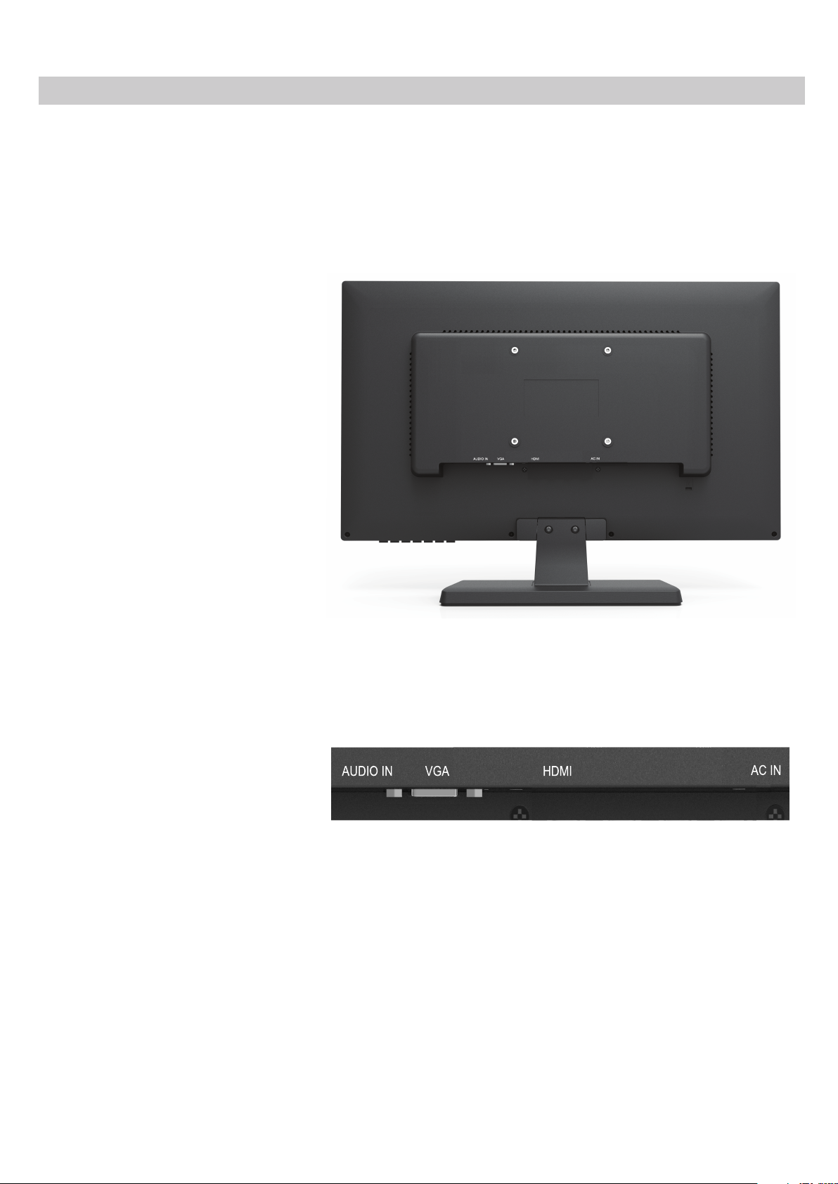
Connections
Back View of Monitor
Connector panel is located on
the underside of the case rear
projection, just above the
stand.
Detailed View of the Connector
Panel
Only use a properly grounded,
three wire cord appropriate
for the local power system.
5
Page 7
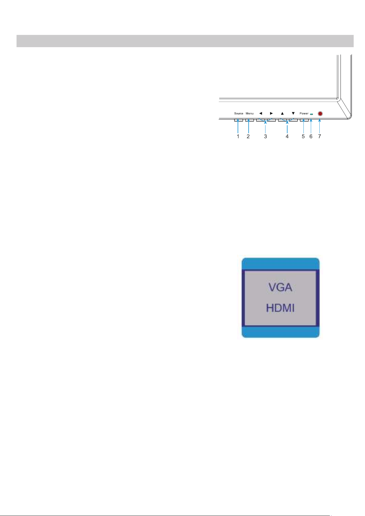
Controls & Menu Operation
Control Keys / Buttons
Buttons are located on the right side of the
Bezel on 0E-19VGHDMI2
/ 22VGHDMI2
models.
Source Auto detection function
when there is/are source(s) connect to the
monitor, monitor will auto detect the source(s) and
auto select the desired source. The source should be
selected manually when there is more than one source
connected to the monitor.
16:9/4:3
A. “SOURCE” button
To change the input selection, pres
SOURCE to display the pop-up menu,
use up/down to highlight the desired
source, then press menu to
complete the selection.
To verify the current input selection,
press SOURCE to display the pop-up,
then press MENU again to dismiss the
pop-up.
s
●Press the button to display
all the signal channel menus.
When Main MENU display as
confirmation key during the
OSD operation
B. “MENU” button
●Press the button to show the OSD
main menu.
C. “LEFT” button
●Press LEFT
button volume down
●Press the LEFT button to scroll
the cursor to desired function.
6
Page 8

D. “RIGHT” button
●Press RIGHT button,
volume increase
E. “DOWN” button
●Press the button to scroll the
cursor to desired function.
Press the DOWN to decrease
the value of selected function in
sub OSD menu.
F. “UP” button
●Press the button to scroll the
cursor to desired function.
●Press the button to increase
the value of selected function in
sub OSD menu.
G. “POWER” button
●Press the button to turn ON or
turn OFF the monitor.
Volume
VOLUME
90
Press buttons to adjust volume on monitor.
Press buttons to adjust volume on remote controller.
One-Touch Button 4:3/16:9 Scale Toggle
Press ▼ button to adjust the aspect ratio of the picture 4:3/16:9 scale toggle.
7
Page 9

Brightness
Press the MENU button to bring the menu on
BRIGHTNESS
screen, and then the up/down buttons to move
up along the main menu selections to choose the
Brightness menu. Press up/down to move
between the left side main menu selector into the
OSD
BRIGHTNESS
CONTRAST
ECO
DCR
STANDARD
OFF
window of menu choices and parameters.
Use the left & right buttons to move the yellow
highlighted
sub-menu selection
within
the submenu. Pressing the right & left buttons will
adjust the value of the highligh
ted item. Press
the SOURCE button to exit the sub-menu and
return to the main menu selector.
To exit the menu system, press the SOURCE. Settings will remain as they appear
on screen.
Adjustments
Brightness: Adjusts the overall picture intensity
Contrast: Adjusts the range of difference between light and dark areas of the picture.
ECO: Adjust the power consumption Standard, Game, Movie, Text..
DCR: Adjust the dynamic contrast ratio ON/OFF.
80
50
8
Page 10

Image
Press the MENU button to bring the menu on
IMAGE
OSD
H-POSITION
V-POSITION
CLOCK
PHASE
ASPECT
16:9
screen, and then up/down buttons to move along
the menu selections to highlight the IMAGE menu.
Press up/down to move between the left side main
menu selector into the window of menu choices
and parameters.
Use the left & right buttons to move the yellow
highlighted
sub-menu selection
within
the submenu. Pressing the right & left buttons will adjust
the value of the highlighted item. Press the
SOURCE button to exit the sub-menu and return to
the main menu selector.
To exit the menu system, press the SOURCE. Settings will remain as they appear
on screen.
Adjustments
H- Position: OSD horizontal position on the screen
50
50
50
50
V-Position: OSD vertical position on screen
Clock: Relative adjustment of horizontal scan rate Phase: Relative adjustment of sync
Phase: Reduce video distortion and instability components
Aspect:
Adjust the aspect ratio (16:9/4:3)
Color Temp
COLOR TEMP
Press the MENU button to bring the menu on
screen, and then up/down buttons to move along
the menu selections to highlight the AUDIO menu.
Press up/down to move between the left /sid
e
main menu selector into the window of menu
RED
GREEN
BLUE
OSD
choices and parameters.
Use the left & right buttons to move the yellow highlighted sub-menu selection within the
sub-menu. Pressing the right & left buttons will adjust the value of the highlighted item.
Press the SOURCE button to exit the sub-menu and return to the main menu selector.
STANDARDCOLOR TEMP
50
50
50
To exit the menu system, press the SOURCE.
9
Page 11

Adjustments
Color Temp
Red
Green
Blue
Adjust red color effect (0-100)
:
:
Adjust blue color effect (0-100).
:
: Adjust color temperature (User/ Cool/ Warm/ Standard)
Adjust green color effect (0-100)
OSD SETTING
Press the MENU button to bring the menu on
screen, and then up/down buttons to move
along the menu selections to highlight the OSD
menu. Press up/down to move the left side main
menu selector into the window of menu choices
and parameters.
Use the left & right buttons to move the
highlighted sub-menu selection within the
sub-menu. Pressing the left & right buttons
will adjust the value of the highlighted item.
Press the SOURCE button to exit the sub-menu
yellow
OSD SETTING
LANGUAGE
OSD H. POS
OSD V. POS
OSD
OSD TIMER
TRANSPARENCY
50
50
10
0
and return to the main menu selector.
To exit the menu system, press SOURCE.
Language: Choose OSD display language from English/French/Spanish
Italian/
Netherlands/
Polish/
Czech/Danish
OSD H. Position: Move the menu position horizontally 0 -100
OSD V. Position: Move the menu position vertically 0 -100
OSD Timer: Adjust the auto off time of the OSD menu between 5 -60 seconds
Transparency: Adjust the transparency of the menu 0-100
10
Page 12

Reset
Press the MENU button to bring the menu on
screen, and then up/down buttons to move
along the menu selections to highlight the
RESET menu. Press up/down to move
between the left side main menu selector into
the window of menu choices and parameters.
Use the left & right buttons to move the
yellow highlighted sub-menu selection within
the sub- menu. Pressing the left & right
IMAGE AUTO ADJUST
COLOR AUTO ADJUST
RESET
OSD
RESET
ONPREVENT BURN IN
buttons will adjust the value of the highligh
ted item.
Press the SOURCE button to exit the sub-menu
and return to the main menu selector.
To exit the menu system, press the SOURCE button twice
Adjustments
Image auto adjust: Auto restore the picture setting
Color auto adjust: Auto restore the color setting
Reset: Restore the factory settings
Prevent Burn in: Prevent-Burn-In is an innovative technology to prevent after images or
ghost images on the LCD display while the monitor is running 24/7/365 in commerivial
applications.
11
Page 13

MISC
Press the MENU button to bring the menu
on screen, and then left/right buttons to move
along the menu selections to highlight the
MISC menu. Press up/down to move between
SIGNAL SOURCE HDMI
VOLUME
MISC
the left side main menu selector into the
window of menu choices and parameters.
Use the left & right buttons to move the yellow
highlighted sub-menu selection within the sub-
OSD
1920x1080 60Hz
menu. Pressing the left & right buttons will
adjust the value of the highlighted item.
Press the SOURCE button to exit the sub-menu and return to the main menu selector.
To exit the menu system, press the SOURCE button twice.
Adjustments
50
Signal Source: Switching signal HDMI/VGA
Volume: Adjust volume for 0-100
12
Page 14

Mounting Guide
Wall or Other Mounting with VESA Standard
CAUTION The wall mount must bear a minimum of five times
the monitor’s net weight. To mount your MONITOR to the wall
or another surface, you need to purchase a VESA wall mount.
Use four PM
removed in step 1 below are PM
Ф4.0 x 6mm screws (the base attachment screws
Ф4.0 x6mm) to attach the mount.
The monitor mount VESA hole pattern is ( 0E-19VGHDMI2
/ 22VGHDMI2 (100mm x 100mm))
Note: Metric (PM
Ф4.0 x 6 mm) is the type screw that should be used (do not use longer
screws or the monitor may be damaged).
1. Before mounting the monitor, remove the base riser (vertical portion of the base) by
removing the four screws near the top with a screwdriver. Then the base and the
riser can be removed. In order to prevent losing these screws, we suggest repl
acing
the screws in their original holes.
2. Attach the VESA mount ( 0E-19VGHDMI2 / 22VGHDMI2 (100mm x 100mm))
plate to the rear of the monitor and follow all of the instructions provided with the
mount to complete the mounting process.
13
Page 15

Accessories
Power Cable
Qty: 1
Screws for Mounting Monitor
Screws Type: PMФ4.0x6mm Qty: 4
PMФ4.0x8mm Qty: 4
Hinge Cover
Qty: 1
HDMI Cable VGA Cable Audio Cable
Qty: 1 Qty: 1 Qty: 1
Screws for Securing Base of Stand
Screws Type: BBФ4.0×7mm Qty: 5
Base of Stand
Qty: 1 Qty: 1
Stand Support User Manuals
Screws for Installing Monitor Stand
Screws Type: BMФ4.0×8mm Qty: 2
HD PRO-GRADE
LED COLOR MONITOR
Tech Support
#833-574-9124(Option2)
info@wboxtech.com
0E-19VGHDMI2
0E-22VGHDMI2
Qty: 2
Power Indicator / Modes of Operation
LED Indicator
LED is off when power is off, LED glows blue when power is on, LED glows red when
monitor is sleep/standby model. The power management feature of the monitor is
designed for security surveillance applications. When there is no video, the monitor
remains ON to be instantly ready to display video when the source is changed or if a PC
changes state from sleep/standby to active
slowly across the screen until video is restored.
mode. A floating “No Signal” box moves
14
Page 16

Dimensions
Model 0E-19VGHDMI2 0E-22VGHDMI2
Letter Dimension mm inch mm inch
A Width of monitor body 441.4 17.37 507 19.96
B Height of monitor body 271 10.66 311.2 12.25
C Depth of monitor body 46 1.81 51.2
2
D Height of monitor on base 332.3 13.08 370.3 14.58
E Width of base 252.2 9.93 252.2 9.93
F Depth of base 149.1 5.87 149.1 5.87
G Width of viewable area 411 16 477.8 18.8
H Height of viewable area 232 9.13 269.4 10.6
I Thickness of monitor 19.5 0.76 22 0.866
J Bottom bezel width 22.5 0.88 22.7 0.89
K Side bezel width 15 0.59 14.6 0.57
15
Page 17

Specifications
Model 0E-19VGHDMI2 0E-22VGHDMI2
Screen Diagonal Dimension (inches)
Viewable Area W x H (inches) 16.13*9.07
Led Type
Pixel Pitch (mm)
Screen Maximum Resolution
Display Resolutions
Supported Input Resolutions
Refresh Rate (Hz)
Color Depth (M)
Brightness(cd/㎡)
Auto Adjust
Monitor Aspect Ratio
Display Aspect Ratio
Horizontal TV Lines
Contrast Ratio
Response Time (ms)
View Angle H/V (degrees)
Digital Video Inputs
Analog Inputs (stereo)
Audio Inputs (stereo)
Speakers (W)
Stand-by (W)
Power Consumption
Monitor Body Dimensions (inches) 17.37*10.66*1.81
Dimensions Monitor + Stand (inches) 17.37*13.08*5.87
Panel Surface
Case & Stand Material
VESA Mounting Pattern (mm)
Base/Stand Included
Base Tilt Angle
Weight Cabinet Only (Ib.)
Weight Cabinet + Base Stand (Ib.)
Power supply (internal)
Operating Temperature
Storage Temperature
Operating Humidity
Accessories
Rack Mount Screw Size (mm)
Certifications
Warranty
640 x 480; 800 x 600; 1024 x 768;
1280 x 1024; 1366 x 768
640 x 480; 800 x 600; 1024 x 768;
1280 x 1024; 1366 x 768
1000:1 SCR or 1,000,000:1DCR
170° x 150°/CR>10 170°x 160°/CR>10
HDMI up to 1366 x 768
VGA up to 1366 x 768
Screws for Mounting Monitor, Screws Type: PMФ4.0x6mm/4pcs/ PMФ4.0x8mm/4pcs
Screws for Securing Base of Stand, Screws Type: BBФ4.0×7mm/5pcs
Screws for Installing Monitor Stand, Screws Type: BMФ4.0x8mm/2pcs
18.5
LED
0.30x0.30
1366 x 768 1920 x 1080
640 x 480; 800 x 600;1024 x 768;
1280 x 1024; 1600 x 900; 1920 x 1080
640 x 480; 800 x 600; 1024 x 768;
1280 x 1024; 1600 x 900; 1920 x 1080
60
16.7
250
Yes
16:9
OSD selectable 16:9 or 4:3
768 1080
5(GTG)
HDMI up to 1920 x 1080
VGA up to 1920 x 1080
1x3.5mm mini-jack
2 x 3
<0.5
18W Typical 20W Typical
19.96*14.58*5.87
Matte black
Plastic
100 x 100
Yes
-5°~15°
5.1
5.7
AC 100-240V~50/60Hz 1.1A
0°C~40°C / 32℉~104℉
-20°C~50°C / -4℉~122℉
10~90%
Power cable/HDMI cable/VGA cable/Audio cable/Hinge cover
Screws/Base of stand/Stand support/User manuals
CE/FCC/ROHS/HDMI/UL/WEEE/REACH
30 Months
21.5
18.76 x 10.56
0.248x0.248
1000:1SCR
19.96*12.25* 2
6.8
7.3
16
Page 18

Limited Warranty
1. Limited Warranty
A. General
Subject to the terms and conditions of this Limited Warranty, from the date of sale
through the period of time for product categories specified in Section 1(b), ADI warrants
its W Box Technologies products to be free from defects in materials and workmanship
under normal use and service, normal wear and tear excepted. Except as required by
law, this Limited Warranty is only made to Buyer and may not be tran
party.
ADI shall have no obligation under this Limited Warranty or otherwise if:
(I) The product is improperly installed, applied or maintained;
(II) The product is installed outside of stated operating parameters, altered, or
improperly services or repaired;
sferred to any third
(III) Damage is caused by outside natural occurrences, such as lightning, power
surges, fire, floods, acts of nature, or the like.
(IV) Defects resulting from unauthorized m
causes unrelated to defective materials or workmanship, or failures related to
batteries of any type used in connection with the products sold here under.
ADI only warrants those products branded as W Box Technologies products and sold by
ADI. Any other products branded by third parties are warranted by the third party
manufacturer for a period as defined by the third party manufacturer, and A
Buyer those warranties and only those warranties extended by such third party
manufacturers or vendors for non-ADI branded products. ADI does not itself warrant any
non-ADI branded product and sells only on an as is basis in accordance with ADI’s
terms and conditions of sale.
odification, misuse, vandalism, or other
DI assigns to
17
Page 19

B. Specific Warranties for Product Categories
Analog Cameras
36 months
DVR’s, NVR’s (excluding HDD)
60 months
IP Cameras
60 months
Extension Cords
Limited Lifetime
HDMI Cables
Limited Lifetime
Jacks, Cords and Intrusion
Limited Lifetime
Product Categories Warranty
CCTV Power Supplies 24 months
Monitors 30 months
Video Baluns 30 months
Racks 60 months
TV Mounts 60 months
Analog Cables Limited Lifetime
B Connectors Limited Lifetime
Patch Cables Limited Lifetime
Wire Ties Limited Lifetime
2. Exclusion of Warranties, Limitation of Liability
THERE ARE NO WARRANTIES OR CONDITIONS, EXPRESS OR IMPLIED, OF
MERCHANTABILITY, OR FITNESS FOR A PARTICULAR PURPOSE OR OTHERWISE,
WHICH EXTEND BEYOND THE DESCRIPTION ON THE FACE HEREOF. TO THE
FULLEST EXTENT PERMITTED BY LAW, IN NO CASE SHALL ADI BE LIABLE TO
ANYONE FOR ANY (I) CONSEQUENTIAL, INCIDENTAL, INDIRECT, SPECIAL, OR
PUNITIVE DAMAGES ARISING OUT OF OR RELATING IN ANY WAY TO T
AND.OR FOR BREACH OF THIS OR ANY OTHER WARRANTY OR CONDITION,
EXPRESS OR IMPLIED, OR UPON ANY OTHER BASIS OF LIABILITY WHATSOEVER,
EVEN IF THE LOSS OR DAMAGE IS CAUSED BY ADI’S OWN NEGLIGENCE OR FAULT
AND EVEN IF ADI HAS BEEN ADVISED OF THE POSSIBILITY OF SUCH LOSSES OR
DAMAGES.
HE PRODUCT
18
Page 20

Any product description (whether in writing or made orally by ADI or ADI’s agents),
specifications, samples, models, bulletin, drawings, diagrams, engineering sheets, or
similar materials used in connection with the Buyer's order are for the sole purpose of
identifying ADI's products and shall not be construed as an express warranty or condition.
Any suggestions by ADI or ADI's agents regarding use, applications or suitability of th
e
products shall not be construed as an express warranty or condition unless confirmed to
be such in writing by ADI. ADI does not represent that the products it sells may not be
compromised or circumvented; that the products will prevent any personal injury
or property loss by burglary, robbery, fire or otherwise, or that the products will in all cases
provide adequate warning or protection. Buyer understands and will cause its customer to
understand
that a properly installed and maintained product is not insurance or guarantee
that such will not cause or lead to personal injury or property loss. CONSEQUENTLY ADI
SHALL HAVE NO LIABILITY FOR ANY PERSONAL INJURY, PROPERTY DAMAGE OR
OTHER LOSS BASED ON ANY CLAIM AT ALL INCLUDING A CLAIM THAT THE
PRODUCT FAILED TO GIVE WARNING. However, if ADI is held liable whether directly or
indirectly for any loss or damage with respect to the products it sells, re
gardless of cause or
origin, its maximum liability shall not in any case exceed the purchase price of the product,
which shall be fixed as liquidated damages and not as a penalty and shall be the complete
and exclusive remedy against ADI.
FOR THE AVOIDANCE OF DOUBT, ADI DOES NOT SEEK HEREUNDER TO EXCLUDE
OR RESTRICT ITS LIABILITY IN RELATION TO (I) FRAUD, (II) DEATH OR PERSONAL
INJURY DIRECTLY RESULTING FROM ITS NEGLIGENCE OR (III) ANY MATTER IN
RESPECT
OF WHICH, BY LAW, IT IS NOT PERMITTED TO RESTRICT ITS LIABILITY.
3. Limitation on Liability to Buyer’s Customers
Buyer agrees to limit liability to its customers to the fullest extent permitted by law. Buyer
acknowledges that ADI shall only be deemed to give consumers of its products such
statutory warranties as may be required by law and at no time shall Buyer represent to its
customers and/or users of ADI products that ADI provides any
accepting the products, to the fullest extent permitted by law, Buyer assumes all liability for,
and agrees to indemnity and hold ADI harmless against and defend ADI from, any and all
suits, claims, demands, causes of action and judgments relating to damages, whether for
personal injury or to personal property, suffered by
any person, firm, corporation or business association, including but not limited to, Buyer's
tomers and/or users of the products because of any failure of the products to detect
cus
and/or warn of the danger for which the goods were designed or any other failure of the
products whether or not such damages are caused or contributed to by the sold or joint
concurring negligence or
fault of ADI.
additional warranties. By
19
Page 21

4. Returns
Subject to the terms and conditions listed below, during the applicable warranty period,
ADI will replace Product or provide a credit at purchase at its sole option free of charge
any defective products returned prepaid. Any obligations of ADI to replace Limited
Lifetime warranty products pursuant to this warranty which result from defect are limited
to the availability of replacement product. ADI reserves the right to re
place any such
products with the then currently available products, or provide a credit in its sole
discretion. In the event Buyer has a problem with any ADI product, please call your local
ADI branch for return instructions:
WWW.WBOXTECH.COM
Be sure to have the model number and the nature of the problem available. In the event of
replacement, the return product will be credited to Buyer's account and a new invoice
issued for the replacement item. ADI reserves the right to issue a credit only in lieu of
replacement.
If any W Box Technologies product is found to be in good working order or such
product's inability to function properly is a result of user damage or abuse, the
p
roduct will be
returned to Buyer in the same condition as received and Buyer shall
be responsible for any return freight changes.
5. Governing Law
This Limited Warranty shall be governed by the laws of England and Wales.
6. Miscellaneous
Where any term of this Limited Warranty is prohibited by such laws, it shall be null and void,
but the remainder of the Limited Warranty shall remain in full force and effect.
20
Page 22

0E-19VGHDMI2
Tech Support
#833-574-9124(Option2)
info@wboxtech.com
wboxtech.com
E505978
LED MONITOR
1 1 9 1 4 0 2 9 7 3
18
0E-22VGHDMI2
1 1 9 1 4 0 2 9 7 5
58
 Loading...