

Page 1

Operator’s Manual
Model AC68
Digital Clamp-On
Multimeter
• Bedienungsanleitung
• Manual de Instrucciones
• Manuel d’Utilisation
¤
TM
Clamp-On Meter
Page 2

WARRANTY
The AC68 Digital Clamp Meter are warranted against any defects of material or
workmanship within a period of one (1) year following the date of purchase of the multimeter by the original purchaser or original user.
Any multimeter claimed to be defective during the warranty period should be
returned with proof of purchase to an authorized Wavetek Meterman Service Center or
to the local Wavetek Meterman dealer or distributor where your multimeter was purchased. See maintenance section for details.
Any implied warranties arising out of the sale of a W
avetek Meterman multimeter,
including but not limited to implied warranties of merchantability and fitness for a particular purpose, are limited in duration to the above stated one (1) year period. Wavetek
Meterman shall not be liable for loss of use of the multimeter or other incidental or consequential damages, expenses, or economical loss or for any claim or claims for such
damage, expenses or economical loss.
Some states do not allow limitations on how long implied warranties last or the
exclusion or limitation of incidental or consequential damages, so the above limitations
or exclusions may not apply to you.
This warranty gives you specific legal rights, and you may also have other rights
which vary from state to state.
D • GEWÄHRLEISTUNG
Die Zangenmultimeter AC68 ist ab Kaufdatum für ein (1) Jahr gegen Material- und
Herstellungsfehler gewährleistet. Siehe Kapitel "Unterhalt und Reparatur" für
Einzelheiten.
Implizierte Schadeforderungen sind auch auf ein Jahr beschränkt. W
avetek Meterman
ist nicht ansprechbar für Gebrauchsverluß oder Folgeschäden, Ausgaben,
Gewinnverluß, usw.
E • GARANTIA
Este Pinza de corrienye Modelo AC68 está garantizado contra cualquier defecto de
material o de mano de obra durante un periodo de un (1) año contado a partir de la
fecha de adquisición. En la sección de "Mantenimiento y Reparación" se explican los
detalles relativos a reparaciones en garantía.
Cualquier otra garantía implícita está también limitada al periodo citado de un (1)
año. Wavetek Meterman no se hará responsable de pérdidas de uso del multí metro, ni
de ningún otro daño accidental o consecuencial, gastos o pérdidas económicas, en
ninguna reclamación a que pudiera haber lugar por dichos daños, gastos o pérdidas
económicas.
F • GARANTIE
Le multimètre-pince Modèle AC68 est garanti pour un (1) an à partir de la date
d’achat contre les défauts de matériaux et de fabrication. Voir chapitre "Maintenance et
Réparation" pour plus de détails.
T
oute garantie impliquée est également limitée à un an. Wavetek Meterman ne peut
être tenu responsable pour perte d’utilisation ou autres préjudices indirects, frais, perte
de bénéfice, etc.
Page 3
– 1 –
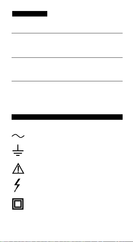
EXPLANATION OF SYMBOLS
D • Erklärung der Symbole = E • Significado de los símbolos = F • Explication des Symboles
Attention! Refer to Operating Instructions •D• Achtung! Bitte Anleitung
lesen •E• ¡Atención! Consulte las Instrucciones de Uso •F• Attention!
Consultez le manuel.
Ground connection •D• Erdanschluß •E• Conexión a tierra
•F• Connection de terre.
Alternating current •D• Wechselstrom •E• Corriente alterna
•F• Courant alternatif.
Dangerous voltage may be present at terminals •D• Eine gefährliche
Spannung kann an den Eingängen anliegen •E• Puede haber tensión
peligrosa en los terminales •F• Une tension dangereuse peut être
présente aux entrées.
This instrument has double insulation •D• Dieses Gerät ist doppelt
geisoliert •E• Este instrumento tiene doble aislamiento •F• Cet
appareil est prévu d’une double isolation.
CONTENTS
D • Inhalt
E • Contenidos
F • Contenu
Safety Information ............................................... 2
Instrument Familiarization................................... 4
Measurement Procedures ................................... 7
Specifications ................................................... 15
Troubleshooting and Repair .............................. 22
Sicherheitsinformationen .................................... 2
Vorstellung des Gerätes....................................... 5
Meßprozeduren ................................................... 7
Spezifikationen ................................................. 16
Fehlersuche und Reparatur ............................... 22
Información de seguridad ................................... 3
Familiarización con el instrumento...................... 5
Procedimientos de medida .................................7
Especificaciones ............................................... 18
Mantenimiento y reparación .............................22
Informations de Sécurité ..................................... 3
Présentation de l’Appareil ................................... 5
Procédures de Mesure ........................................ 8
Spécifications ................................................... 20
Dépannage et Réparation .................................. 22
Page 4

WARNINGS AND PRECAUTIONS
■ This instrument is EN61010-1, EN61010-2-032 certified for Installation
Category III. It is recommended for use in distribution level and fixed
installations, as well as lesser installations, and not for primary supply
lines, overhead lines and cable systems. ■
This instrument must not be
used on uninsulated conductors at a voltage greater than 600V ac/dc.
■
Do not exceed the instrument overload limits per function (see
specifications) nor the limits marked on the instrument. ■ Exercise
extreme caution when: measuring voltage >20V // current >10mA // AC
power lines with inductive loads // AC power lines during electrical storms
// servicing CRT equipment. High voltages can be lethal and high voltage
transients may occur at any time. ■ Always inspect your instrument, test
leads and accessories for signs of damage or abnormality before every
use. If abnormal conditions exist (broken or damaged test leads, cracked
case, display not reading, etc.), do not use. ■ When making voltage
measurements, make sure these ranges function correctly. Take a reading
of a known voltage first. ■ Never measure current with the test leads
inserted in the input jacks ■ Never ground yourself when taking
measurements. Do not touch exposed metal pipes, outlets, fixtures, etc.,
which might be at ground potential. Keep your body isolated from ground
and never touch exposed wiring, connections, test probe tips, or any live
circuit conductors. ■ Do not operate the instrument in an explosive
atmosphere (flammable gases, fumes, vapor, dust.) ■ Do not use this or
any piece of test equipment without proper training.
D • Warnungen und Vorsichtsmaßnahmen
■
Dieses Gerät ist EN61010-1, EN61010-2-032 zertifiziert für Installationsklasse III. Anwendung ist empfohlen auf Verteilerebene und festen Anlagen
sowie untergeordneten Systemen, jedoch nicht für Starkstromnetze und
Hochspannungsanlagen.
■
Dieses Gerät darf nicht mit nicht-isolierten Leitern
bei Spannungen höher als 600V AC/DC verwendet werden.
■
Überschreiten Sie
nie die kontinuierlichen Überlastgrenzen der verschiedenen Meßfunktionen
(siehe Spezifikationen) oder andere Grenzen welche auf dem Gerät markiert sind.
■
Vorsicht beim Messen von Spannungen >20V // Strömen >10mA //
Netzstrom/-spannung bei induktiver Last oder bei Gewittern // Strom, wenn die
Sicherung durchbrennt in einem Schaltkreis mit Leerlaufspannung >600V
(>250V beim mA Eingang) // beim Messen an Bildröhrgeräten (hohe
Spannungsspitzen)
■
Unsersuchen Sie Gerät, Meßkabel, Verbinder, usw. vor
jeder Messung. Beschädigte Teile nicht verwenden
■
Wenn Sie
Spannungsmessungen vornehmen, vergewissern Sie sich zuerst daß diese
– 2 –
Page 5

Bereiche gut funktionieren. Messen Sie zuerst eine bekannte Spannung. ■ Vor
jeder Strommessung Meßkabel unbedingt abziehen
■
Meßspitzen und
Stromkreis während der Messung nicht berühren. Sich selbst isolieren !
■
Gerät nicht in explosiver Umgebung verwenden.
E • Advertencias y Precauciones
■
Este instrumento está homologado según EN61010-1, EN61010-2-032 para
la Categoría de Instalación III. Su uso está recomendado en el nivel de
distribución y en instalaciones fijas, así como en instalaciones menores, pero
no en líneas principales de suministro, líneas aéreas ni sistemas de cable.
■
No debe utilizarse este instrumento sobre hilos sin aislar a tensiones superiores
a 600 V CA/CC
■
No supere nunca los límites de entrada para las diferentes
funciones (vea Especificaciones), ni los límites marcados en el instrumento.
■
Tenga especial cuidado: al medir tensión >20 V // corriente >10 mA // tensión
de red de CA con cargas inductivas // tensión de red de CA durante tormentas
eléctricas // mientras trabaja con pantallas TRC
■
Inspeccione siempre el
multímetro, las puntas de prueba y los accesorios antes de cada uso. No utilice
ningún componente dañado.
■
Cuando se hacen medidas de voltaje, asegúrese
que las funciones de rango funcionan correctamente. Haga la lectura de un
voltaje conocido primero.
■
nunca mida corriente con la puntas de prueba
puestas en los conectores de entrada.
■
Nunca se ponga Ud. a tierra cuando
esté tomando medidas. No toque nunca circuitos expuestos ni partes metálicas.
Mantenga su cuerpo aislado de tierra.
■
No utilice el instrumento en ambientes
potencialmente explosivos.
F • Avertissements et Précautions
■
Cet instrument est certifié EN61010-1, EN61010-2-032 catégorie
d’installation III. Son utilisation est recommandée pour le niveau de distribution
de réseau, les installations fixes et systèmes subordonnés, et non pour les
installations de puissance et lignes de transmission et câblages à haute tension.
■
N’utilisez pas cet appareil avec des conducteurs non-isolés à des tensions
supérieures à 600V ca/cc.
■
N’excédez jamais les limites de surcharge
continues par fonction (voir spécifications) ou d’autres limites marquées sur
l’appareil.
■
Soyez très prudent quand vous mesurez des tensions >20V ou des
courants >10mA // tension ou courant de secteur avec charge inductive ou par
temps de tempête // dans des appareils à tube cathodique (transitoires à haute
tension)
■
Inspectez appareil, câbles, connecteurs avant chaque mesure.
N’utilisez pas des pièces endommagées
■
Quand vous mesurez une tension,
assurez-vous que ces gammes fonctionnent correctement. Mesurez d’abord une
tension connue.
■
Ne mesurez pas du courant avec les cordons de mesure
raccordés
■
Ne touchez pas les pointes de touche ou le circuit pendant les
mesures. Isolez-vous !
■
N’utilisez pas cet appareil dans des atmosphères
explosives.
– 3 –
Page 6

INTRODUCTION
Unpacking and Inspection
Your shipping carton should include the digital clamp meter, a carrying
case, one test lead set (one black, one red), one 9V battery (installed), and
this manual. If any of the items are damaged or missing, return the
complete package to the place of purchase for an exchange.
D • Lieferumfang
Die Verpackung sollte enthalten: ein digitales Zangenmultimeter, eine
Tragetasche, ein Paar Meßkabel (ein schwarz, ein rot), eine 9V Batterie (im
Gerät) und diese Anleitung. Sollte ein Teil beschädigt sein oder fehlen, kehren
Sie bitte zur Verkaufsstelle zurück für einen Umtausch.
E • Desembalaje e inspección
El embalaje debe contener el multímetro de pinza, un estuche de transporte, un
juego de puntas (una negra y otra roja), una pila de 9 V (instalada) y este
manual. Si falta algún componente u observa daños, devuelva el conjunto al
lugar donde lo adquirió para que se lo cambien.
F • Désemballage
Votre emballage devrait contenir: un multimètre-pince, une sacoche, une paire
de cordons de test (un noir, un rouge), une pile 9V (dans l’appareil) et ce
manuel. Si une pièce manque ou est endommagée, retournez à votre point de
vente pour un échange.
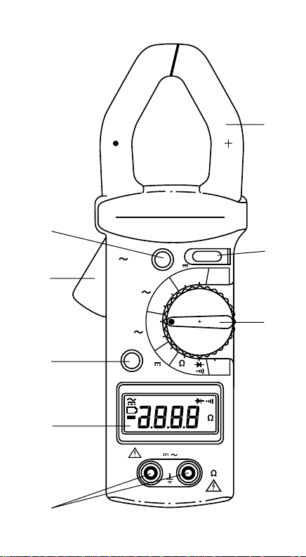
Instrument Familiarization
1) Transformer Jaws: Designed to pick up the current flowing through the
conductor.
2) Jaw Opening Lever: Press lever to open transformer jaws. Release pressure
to close the jaws.
3) Digital Display: 3 3/4 digit LCD (max. reading 3999), with decimal point,
AC/DC, polarity, unit and low battery ( ) indicators.
4) Function/Range Selector: Selects the desired function and range. Changing
position turns instrument back on after Auto-OFF.
5) Peak Hold Button: Toggles on and off. Captures the maximum peak value of
a current or voltage surge (motor sturt-up). “PEAK” is shown on LCD.
6) Data Hold Button: Toggles on and off. Holds reading for all functions and
ranges. Always release HOLD before taking a new measurement. “HOLD” is
shown on LCD.
7) DCA ZERO Button: Push this button to zero the display before measuring DC
current.
8) Input Terminals: Always connect black test lead (negative) to black COM
input jack and red test lead to red “VΩ” input jack for voltage, frequency,
resistance, continuity and diode measurements.
– 4 –
BT
Page 7
– 5 –
➁
➂
➄
➇
➆
➀
➅
➃
AC68 AC/DC
400
600
600V
A
400
600
HOLD
MAX CAT III
HOLD
KHz
PEAK
A
600
400
V
600
V
DCA ZERO
PEAK
BT
600V
COM V
OFF
Hz
VA
K
Page 8

D • Vorstellung des Gerätes
1) Stromzange: Überträgt den Strom der durch den Leiter fließt
.
2) Zangenhebel: Hebel drücken um Zange zu öffnen. Zange schließt beim
Loslassen des Hebels.
3) Digitale Anzeige: 3 3/4-stelliges LCD (max. Ablesung 3999), Dezimalpunkt,
AC/DC, Polaritäts-, Einheits- und entladene
()
Batterie Anzeigen.
4) Funktionsschalter: Wählt die gewünschte Funktion und Bereich.
Positionswechsel schaltet das Gerät nach automatischer Abschaltung wieder
ein.
5) Spitzenwertspeichertaste: Speichert den maximalen Spitzenwert von Strom
oder Spannung. (Motoreneinschaltung). “PEAK” wird angezeigt.
6) Data Hold Taste: Friert die Anzeige für alle Bereiche und Funktionen. HOLD
erneut drücken (lösen) bevor Sie eine neue Messung vornehmen.
7) Nullabgleichtaste für Gleichstrommessung: Diese Taste drücken bevor Sie
eine Gleichstrommessung vornehmen.
8) Eingänge: Für Spannungs-, Widerstands-, Durchgangs- und Diodenmessungen, das schwarze Meßkabel immer mit COM Eingang und rotes immer
mit VΩ Eingang verbinden.
E • Familiarización con el instrumento
1) Pinza del transformador: Diseñada para captar la corriente que fluye por el
hilo.
2) Palanca de apertura de la pinza: Presione sobre esta palanca para abrir la
pinza del transformador. La pinza se cierra de nuevo al liberar la presión.
3) Pantalla digital: visualizador LCD de 3
3/4 dígitos (lectura máxima 3999),
punto decimal, indicadores de AC/DC, polaridad, unidades y pila baja
().
4)
Selector de Funciones / Rango: Seleccione la función y rango deseado.
Cambiando la posición reactiva el instrumento despues de un “Auto-Off”.
5) Control de congelar valor máximo: Bascula entre conectado / desconectado,
capturando el valor máximo de la corriente o voltaje transitorio (arranque de
motores eléctricos). El valor máximo marcado como “Peak” es mostrado en
pantalla
.
6) Tecla de retención de datos: (HOLD) Bascula entre conectado / desconectado.
Congela la lectura en todas las funciones y escalas. Libere siempre HOLD antes
de tomar una nueva medida.
“HOLD” es mostrado en pantalla.
7)
Control “DCA ZERO”: Pulse este control para poner a cero la pantalla antes
de medir corriente en contínua.
8) Terminales de entrada: La punta de prueba negra se conecta siempre a la
entrada “COM”, y la roja a la entrada “V-Ω“, para medir tensión, frequencia,
resistencia, continuidad y diodos.
F • Présentation de l’appareil
1) Pince: Capte le courant qui passe par le conducteur.
2) Levier de la Pince: Poussez ce levier pour ouvrir la pince. La pince ferme
quand la pression est relachée.
– 6 –
BT
BT
Page 9

3) Affichage Digital: LCD 3 3/4 digits (3999 points), point décimal , indicateurs
CA/CC, de polarité, d’unités et de pile déchargée
()
.
4) Sélecteur de fonctions et de gammes.
Un changement de position rallume
également l’appareil après une cupure automatique.
5) Mémoire de valeurs-crête: Enregistre la valeur-crête du courant ou de la
tension (ex.: mise en route d’un moteur). “PEAK” est affiché.
6) Maintien de lecture: Maintient la lecture pour toutes fonctions et gammes.
“HOLD” est affiché. Désactivez HOLD pour prendre de nouvelles mesures.
7) Mise à Zéro pour mesures de courant continu: Pressez ce bouton avant de
prendre une mesure de courant continu.
8) Entrées: Pour les mesures de tension, de résistance, de continuité, de
fréquence et de diodes, connectez toujours le cordon de mesure noir à l’entrée
COM, et le rouge à l’entrée VΩ.
MEASURING PROCEDURES
General
❶ Make sure that the selected function and range are suitable for the
measurement to be taken.
❷ If the measured current is higher than the selected
range for a longer period of time, overheating may occur, compromising the
safety and operation of inner circuits.
❸ Do not measure currents on high
voltage conductors (>600V) to avoid risks of discharge and/or incorrect
readings.
❹ When measuring current, make sure that the test leads are removed
from the meter terminals.
➎ The most accurate current reading will be obtained
by placing the conductor in the center of the jaws (aligned with the centering
marks on the transformer jaws).
D • Meßprozeduren
Allgemein:❶Stellen Sie sicher daß gewählte Funktion und Bereich mit
der vorzunehmenden Messung übereinstimmen.
❷
Wenn der gemessene
Strom den gewählten Bereich längere Zeit überschreitet, kann Überhitzung
auftreten welche die Sicherheit und Funktion der inneren Schaltkreise
gefährdet.
❸
Messen Sie keinen Strom an Hochspannungskabeln (>600V)
um elektrische Schläge und/oder ungenaue Messungen zu vermeiden.
❹
Wenn Sie Strommessungen vornehmen, stellen Sie sicher daß die
Meßkabel vom Gerät abgezogen sind.
➎
Die größte Meßgenauigkeit wird
erreicht, wenn der Stromleiter in der Zangenmitte liegt (in Übereinstimmung
mit den Markierungen auf der Zange).
E • Procedimientos de medida
Genérico:❶Asegúrese que la función y el rango son los adecuados a la
medida a realizar.
❷
Si la corriente a medir es mayor que el rango
seleccionado durante un período de tiempo largo, podríamos tener un
sobrecalentamiento, comprometiendo la seguridad y operación de los
circuítos internos.
❸
No mida corriente en conductores de alto voltaje (>
600 voltios), a fin de evitar riesgos de descargas y /o lecturas erróneas.
❹
Cuando mida corriente, asegúrese que las puntas de prueba no estén
conectadas a los terminales del medidor.
➎
La mayor precisión de lectura
– 7 –
BT
Page 10

de corriente, se obtendrá colocando el conductor en el centro de la pinza
(alineado con las marcas que existen en la misma.).
F • Procédures de Mesure
Général:❶Assurez-vous que la fonction et la gamme choisies
correspondent à la mesure que vous voulez effectuer.
❷
Si le courant
mesuré dépasse la gamme choisie durant une période de temps prolongée,
un surchauffement peut se produire, compromettant la sécurité et le bon
fonctionnement des circuits internes.
❸
Ne mesurez pas du courant sur des
conducteurs à haute tension (>600V) afin d’éviter des chocs électriques
et/ou des mesure incorrectes.
❹
Quand vous mesurez du courant, assurez-
vous que les cordons de mesure sont retirés de l’appareil.
➎
La meilleure
précision de mesure est obtenue quand le conducteur de courant est placé
au milieu de de la pince (dans l’alignement des marquages sur la pince).
DC Current Measurement
❶ Set the function/range selector to the appropriate A position (400 or
600A).
❷Press the DCA ZERO button to make sure that the display is zero-
reading. ❸
Open spring-loaded clamp by pressing the lever on left side of
meter.
❹ Position clamp around one wire or conductor and release the clamp
lever. Make sure that the clamp is entirely closed. The clamp must be positioned
around only one conductor. If it is placed around two or more current carrying
conductors, the reading is FALSE.
➎ Read the displayed value. The direction of
the current corresponds to the indication of the pointer on the jaw. Polarity
inversion is indicated by a (minus) symbol on the display.
D - Gleichstrommessung
❶
Wahlschalter auf gewünschte A Position stellen. (400 oder 600A).
❷
Nullabgleichtaste drücken und sicher stellen daß Anzeige auf Null steht.
❸
Zange durch Drücken des Hebels öffnen. ❹Zange um Stromkabel
bringen und schließen (durch Loslassen des Hebels). Stellen Sie sicher daß
nur ein Kabel in der Zange ist und daß die Zange gut geschlossen ist. Bei
mehreren Kabeln in der Zange währe die Messung falsch.
➎
Stromwert
ablesen. Die Richtung des Stromes stimmt mit der Markierung auf der Zange
überein. Umgekehrte Polarität wird mit einem Minus ( ) Symbol auf der
Anzeige angezeigt.
E - Medida de Corriente CC
❶
Coloque el selector de función / rango en la posición apropiada de A
(400 ó 600A.).
❷
Pulse el control de “DCA ZERO”, para asegurarse que la
pantalla lee cero.
❸
Abra la pinza de resorte, presionando sobre la palanca
situada en el lado izquierdo del medidor.
❹
Rodee el hilo o el conductor con
la pinza y suelte la palanca para cerrarla. Asegúrese de que la pinza queda
completamente cerrada. La pinza debe rodear un solo conductor. Si se
coloca rodeando dos o más conductores con corriente, la medida será
FALSA.
➎
Lea el valor mostrado. La dirección de la corriente corresponde
– 8 –
Page 11

a la indicación del puntero en la pinza. La inversión de polaridad está
indicada por un signo en la pantalla.
F - Mesure de Courant Continu
❶
Placez le sélecteur sur la position A désirée (400 ou 600A).
❷
Pressez le bouton de mise-à-zéro et assurez-vous que l’afficheur est bien
bien mis à zéro.
❸
Ouvrez la pince en poussant sur le levier. ❹Placez la
pince autour du conducteur et fermez la (en relachant le levier). Assurezvous que la pince est complètement fermée et qu’elle ne contient qu’un seul
conducteur. Si elle en contient plusieurs, la mesure est faussée.
➎
Lisez la
valeur affichée. La direction du courant correspond au marquage sur la
pince. Une inversion de polarité est indiquée par un symbole (moins)
sur l’afficheur.
AC Current Measurement
❶
Set the function/range selector to the appropriate A position (400 or
600A).
❷ Open spring-loaded clamp by pressing the lever on left side of meter.
❸ Position clamp around one wire or conductor and release the clamp lever.
Make sure that the clamp is entirely closed. The clamp must be positioned
around only one conductor. If it is placed around two or more current carrying
conductors, the reading is FALSE.
❹ Read the displayed value.
D - Wechselstrommessung
❶
Wahlschalter auf gewünschte A Position (400 oder 600A) stellen.
❷
Zange durch Drücken des Hebels öffnen. ❸Zange um Stromkabel bringen
und schließen (durch Loslassen des Hebels). Stellen Sie sicher daß nur ein
Kabel in der Zange ist und daß die Zange gut geschlossen ist. Bei mehreren
Kabeln in der Zange währe die Messung falsch.
❹
Stromwert ablesen.
E - Medida de Corriente CA
❶
Coloque el selector de función / rango en la posición apropiada de A
(400 ó 600A.).
❷
Abra la pinza de resorte, presionando sobre la palanca
situada en el lado izquierdo del medidor.
❸
Rodee el hilo o el conductor con
la pinza y suelte la palanca para cerrarla. Asegúrese de que la pinza queda
completamente cerrada. La pinza debe rodear un solo conductor. Si se
coloca rodeando dos o más conductores con corriente, la medida será
FALSA.
❹
Lea el valor mostrado.
F - Mesure de Courant Alternatif
❶
Placez le sélecteur sur la position A désirée(400 ou 600A). ❷Ouvrez
la pince en poussant sur le levier.
❸
Placez la pince autour du conducteur
et fermez la (en relachant le levier). Assurez-vous que la pince est
complètement fermée et qu’elle ne contient qu’un seul conducteur. Si elle en
contient plusieurs, la mesure est faussée.
❹
Lisez la valeur affichée.
– 9 –
Page 12

DC and AC Voltage Measurement
Warning:The maximum input voltage for DC or AC Volts is 600Vrms. Do
not attempt to take any voltage measurement that exceeds 600Vrms to
avoid electrical shock hazard or damage to the instrument. ❶ Set the
function/range selector to the appropriate V (600V) or V (400 or
600V) position . ❷ Connect the black test lead to the “COM” terminal and
the red test lead to the “VΩ’’ terminal. Connect probe tips to the circuit and
read the value.
D - Gleich- und Wechselspannungsmessung
Warnung: Die maximale Eingangsspannung für Gleich- und Wechsel-
spannungsmessung ist 600Vrms. Messen Sie keine höhere Spannung um
elektrische Schläge und/oder Zerstörung des Gerätes zu vermeiden.
❶
Wahlschalter auf gewünschte Funktion und Bereich stellen V (600V)
oder V (400 oder 600V).
❷
Schwarzes Meßkabel mit COM und rotes mit
VΩ verbinden. Meßspitzen mit Schaltkreis verbinden (parallel mit
Spannungsquelle) und Meßwert ablesen.
E - Medida de Tensión CC o CA
Precaución: El valor máximo de voltaje a la entrada tanto sea en alterna
como en contínua (AC ó DC), es de 600 V. rms. No intente medir voltajes
por encima de este valor a fin de evitar electrocutaciones o daños al
instrumento.
❶
Ponga el selector de función / rango en la posición
apropiada de 600VCC ó 400/600 VCA.
❷
Conecte la punta de prueba negra
al terminal “COM” y la roja al terminal “V-Ω“. Toque los puntos del circuito
con las puntas metálicas y lea el valor de la medida.
F - Mesure de Tension Continue et Alernative
Avertissement: La valeur d’entrée maximale pour la mesure de tension
continue ou alterntive est de 600Veff. Ne mesurez pas une tension
supérieure afin d’éviter des chocs électriques et/ou des dommages à
l’appareil.
❶
Placez le sélecteur sur la fonction et gamme appropriées: V
(600V) ou V (400 ou 600V).
❷
Connectez le cordon noir à l’entrée COM
et le rouge à l’entrée VΩ. Connectez les pointes de touche au circuit (en
parallèle avec la source de tension) et lisez la valeur.
Frequency Measurement
Note: Both ammeter and voltmeter can be used for frequency measurement.
The clamp-on Ammeter detects the frequency of the current circulating in the
cable or bus-bar under test (the current must be greater than 1A in the 400A
range and greater than 15A in the 600A range). The Voltmeter detects the
frequency of the voltage applied to the leads.
❶ In either set-up (current or
voltage measurement), set the function/range switch to the Hz position.
❷Read
the frequency value on the display.
– 10 –
Page 13

D - Frequenzmessung
Anmerkung: Sowohl Ammeter als Voltmeter können zur Frequenzmessung
verwendet werden. Die Stromzange bestimmt die Frequenz des Stromes der
durch die Zange fließt (der Strom muß höher als 1A im 400A Bereich und
höher als 15A im 600A Bereich sein). Das Voltmeter bestimmt die Frequenz
der anliegenden Spannung.
❶
Für jede Meßart, Funktions-
Bereichsschalter auf Hz Position stellen.
❷
Frequenz ablesen.
E - Medida de Frequencia
Nota: Ambos instrumentos pueden ser usados para medir frecuencia. La
pinza amperimétrica detecta la frecuencia de la corriente circulando por el
cable o barra bajo test ( la corriente debe ser mayor de 1A. en el rango de
400A. y mayor de 15A. en el rango de 600A.). El voltímetro detecta la
frecuencia del voltaje aplicado entre las puntas de prueba. En el caso de
arranque inicial (rango de voltaje o corriente), ponga el control de función /
rango en la posición “HZ”. y lea el valor de frecuencia en pantalla.
F - Mesure de Fréquence
Note: L’ampèremètre et le voltmètre peuvent être utilisés pour la mesure de
la fréquence. La pince détecte la fréquence du courant qui circule dans le
conducteur ( le courant doît être supérieur à 1A pour la gamme de 400A et
supérieur à 15A pour la gamme de 600A). Le voltmètre détecte la fréquence
de la tension appliquée.
❶
Pour les deux modes de mesure, placez le
sélecteur sur la position Hz.
❷
Lisez la fréquence sur l’afficheur.
Resistance Measurement
Warning: Before taking any in-circuit resistance measurement, remove power
from the circuit being tested and discharge all capacitors.
❶ Set the
function/range selector to the 4KΩ position.
❷ Connect the black lead to the
COM terminal and red lead to the “VΩ” terminal.
❸ Connect the test leads to
the resistance or circuit to be measured and read the value on the display.
D- Widerstandsmessung
Warnung: For jeder Messung im Schaltkreis, Strom abschalten und
Kondensatoren entladen.
❶
Funktionsschalter auf 4KΩ Position stellen.
❷
Schwarzes Meßkabel mit COM und rotes mit VΩ verbinden. ❸Meßkabel
mit Widerstand oder Schaltkreis verbinden und Meßwert ablesen.
E - Medida de Resistencia
Precaución: Asegúrese de que no hay tensión aplicada a la resistencia y
descargue los condensadores.
❶
Ponga el conmutador deslizante en la
posición 4KΩ.
❷
Conecte la punta de prueba negra al terminal “COM”, y la
roja al terminal “VΩ“.
❸
Conecte las puntas de prueba a la resistencia o
circuito que vaya a medir. Lea el valor de la medida.
– 11 –
Page 14

F - Mesure de Résistance
Avertissement: Avant chaque mesure en-circuit, coupez l’alimentation et
déchargez les condensateurs.
❶
Placez le sélecteur sur la position 4KΩ.
❷
Connectez le cordon noir à l’entrée COM et le rouge à l’entrée VΩ.
❸
Connectez les cordons à la résistance ou au circuit à mesurer et lisez la
valeur sur l’afficheur.
Continuity Measurement
Warning: Before taking any in-circuit continuity measurement, remove power
from the circuit being tested and discharge all capacitors.
❶ Set the
function/range selector to the position.
❷ Connect the black lead to the
COM terminal and red lead to the “VΩ” terminal.
❸ Connect the test leads to
the circuit to be tested. Continuity (resistance ≤40Ω) is indicated by a
continuous beep tone.
D- Durchgangstest
Warnung: For jeder Messung im Schaltkreis, Strom abschalten und
Kondensatoren entladen.
❶
Funktionsschalter auf Position stellen.
❷
Schwarzes Meßkabel mit COM und rotes mit VΩ verbinden. ❸Meßkabel
mit Schaltkreis verbinden. Durchgang (Widerstand ≤40Ω) wird mit einem
Dauerton angezeigt.
E - Medida de Continuidad
Precaución: Asegúrese de que no hay tensión aplicada al circuito y
descargue los condensadores.
❶
Ponga el conmutador deslizante en la
posición .
❷
Conecte la punta de prueba negra al terminal “COM”, y la
roja al terminal “VΩ“.
❸
Conecte las puntas de prueba al circuito que vaya
a medir. El medidor emite un tono continuo si el valor de resistencia es ≤40
Ω
F - Mesure de Continuité
Avertissement: Avant chaque mesure en-circuit, coupez l’alimentation et
déchargez les condensateurs.
❶
Placez le sélecteur sur la position .
❷
Connectez le cordon noir à l’entrée COM et le rouge à l’entrée VΩ.
❸
Connectez les cordons au circuit à mesurer. Une continuité (résistance
≤40Ω) est indiqué par un singnal sonore continu.
Diode Test
❶ Set the function/range selector to the position. ❷ Connect the black
lead to the COM terminal and red lead to the “VΩ” terminal.
❸Connect the red
test lead to the anode, and the black test lead to the cathode of the diode to be
tested.
❹ Read the forward voltage value on the display (approx. 0.6V for a
silicon diode or 0.4V for a germanium diode). An open diode is indicated
by “OL”. ➎Reverse test lead connections to the diode to perform a reverse
– 12 –
Page 15

bias test. “OL” indicates a good diode.
Notes: “OL” for both reverse and forward bias tests indicates an open
diode. A low voltage reading for both bias tests indicates a shorted diode.
If the diode is shunted by a resistor of 1000 ohms or less, it must be
removed from the circuit before taking the measurement. Bipolar transistor
junctions may be tested in the same manner described above as emitterbase and base-collector junctions are diode junctions.
D • Dioden- und Transistortest
❶
Funktionsschalter auf stellen. ❷Rotes Meßkabel mit VΩ Eingang
und schwarzes mit COM Eingang verbinden.
❸
Meßkabel mit Diode
verbinden – rotes mit Anode; schwarzes mit Kathode.
❹
Spannungsabfall in
Durchlaßrichtung ablesen (ung. 0.6V für eine Silikon-Diode und 0.4V für
eine Germaniumdiode. Eine offene Diode wird mit Überlast angezeigt.
➎
Verbindung umdrehen um in Sperrrichtung zu messen. Überlast zeigt eine
gute Diode an.
Anmerkung: Überlast in beiden Richtungen zeigt eine offene Diode an;
eine niedrige Ablesung eine kurzgeschlossene Diode. Transistorübergänge
können wie Dioden getestet werden.
E • Comprobación de diodos y transistores
❶
Ponga el selector de función en la posición . ❷Conecte la punta de
prueba roja a la entrada VΩ y la negra a la entrada COM.
❸
Aplique el
extremo de la punta de prueba roja al ánodo del diodo, y el de la negra al
cátodo.
❹
El visualizador indica la caída de tensión directa
(aproximadamente 0.6 V para diodos de silicio, o 0.4 V para diodos de
germanio). Una unión abierta se indica como condición de sobrecarga.
➎
Invierta la conexión de las puntas de prueba para verificar la polarización
inversa del diodo. La condición de sobrecarga indica un diodo en buen
estado. Notas: La condición de sobrecarga en ambos sentidos indica un
diodo abierto. Un valor bajo de tensión en ambos sentidos indica un diodo
cortocircuitado. Las uniones de un transistor bipolar se comprueban como
si fueran diodos.
F • Test de Diodes et de Transistors
❶
Placez le sélecteur sur . ❷Connectez les cordon rouge à l’entrée
VΩ et le noir à l’entrée COM.
❸
Connectez les pointes de touche à la diode
– le rouge à l’anode, le noir à la cathode.
❹
Lisez la chute de tension en
direction passante (environ 0.6V pour une diode au Si; 0.4V pour une diode
au Ge). Une diode ouverte est affichée par “OL”.
➎
Inversez la connection
pour mesurer en direction de bloquage. Une bonne diode est affichée par
“OL”. Notes: “OL” dans les deux directions indique une diode ouverte; une
lecture basse indique une diode court-circuitée. Les jonctions de transistors
– 13 –
Page 16

peuvent être testées comme des diodes.
Peak Hold Measurement
Proceed as for voltage or current measurement (AC or DC). Before actually
taking the measurement, press the PEAK button. “PEAK” is shown on the
display. After taking a measurement, the displayed reading is the maximum
peak value of a surge in a voltage or current.
D • Spitzenwertspeicher
Prozedur für Spannungs- oder Strommessung folgen (AC oder DC). Bevor
Sie eine Messung vornehmen, PEAK Taste drücken. “PEAK” wird angezeigt.
Die Anzeige hält den maximal gemessenen Spitzenwert fest.
E • Medida de valores máximos
Proceda como en el caso de medición de voltaje o corriente (AC / DC).
Antes de tomar la medida, pulse el control “PEAK”, el cual es mostrado en
pantalla. Después de tomar la medición la lectura mostrada es el valor
máximo de la corriente o voltaje en el caso de transitorios, como al
arrancar un motor eléctrico.
F • Mémoire Crête (Peak Hold)
Suivez la procédure de mesure pour le courant ou la tension (cc ou ca).
Avant de prendre la mesure, pressez la bouton PEAK. “PEAK” apparait sur
l’afficheur. L’afficheur maintient la valeur crête maximale mesurée.
Data Hold
Proceed as for voltage or current measurement (AC or DC). While taking a
measurement, press the HOLD button. “HOLD” is shown on the display and the
current meter reading is maintained, even after disconnecting the test leads from
the circuit or removing the conductor from the clamp. Press HOLD again to
desactivate before taking a new measurement.
D • Anzeigesperre
Probe Hold erhält die Anzeige für spätere Ablesung (auch wenn die
Meßkabel vom Schaltkreis getrennt sind). HOLD vor der Messung drücken.
Hold erneut drücken (lösen), bevor Sie eine neue Messung vornehmen.
E • Retención de Lectura
Proceda como en el caso de medición de voltaje o corriente (AC / DC).
Mientra este tomando una medición, pulse el control “HOLD”.“HOLD” es
mostrado en pantalla lo que producirá un congelado de la medida, incluso
si desconecta las puntas de prueba del circuíto o saca el conductor de la
pinza. Libere siempre HOLD antes de tomar una nueva medida.
F • Maintien de Lecture (Probe Hold)
Probe Hold maintient l’affichage pour lecture ultérieure (même quand les
pointes de touche sont séparées du circuit). Activez HOLD avant la mesure.
Pressez HOLD à nouveau (désactiver) avant de prendre une nouvelle
– 14 –
Page 17

mesure.
SPECIFICATIONS
General Specifications
Display: 3 3/4 Digit LCD, max. reading of 3999. Function and unit indication.
Overrange indication : “OL” indicated.
Polarity indication: automatic; positive implied; negative indicated.
Zero adjustment: automatic for all functions and ranges except DC current (Zero
adjustment button).
Ranging: manual function and range selection with rotary selector switch.
Autoranging for frequency measurement.
Special functions: Data Hold, Peak Hold
Operating principle: dual slope integration
Sampling rate: 2/sec, nominal.
Maximum voltage between any terminal and earth ground: 600V
Low Battery Indication: when battery voltage drops below operating voltage.
Auto Power Off: Approx. 30 minutes after no function change.
Environmental Conditions
Operating temperature: 0 °C to +40 °C, <80% R.H., non-condensing
Storage temperature: -10 °C to +60 °C, <70% R.H., battery removed.
Power source: Single 9V battery (NEDA 1604,1EC 6F22)
Battery life: Alkaline 200 hours.
Maximum jaw opening: 40mm (1.57 inches)
Pollution degree: Level II
Size (WxLxH): 76x228x39mm (3”x9”x1.5”); Weight: 465gr (incl. battery)
Accessories: Test leads, battery, manual and carrying case.
Safety: Meets EN61010-1 Cat III 600V. EN61010-2-03
EMC: Meets EN55011, EN61000-4-2,4
EMC: This product complies with requirements of the following
European Community Directives: 89/336/EEC (Electromagnetic
Compatibility) and 73/23/EEC (Low Voltage) as amended by 93/68/EEC (CE
Marking).
However, electrical noise or intense electromagnetic fields in the vicinity of the
equipment may disturb the measurement circuit. Measuring instruments will
also respond to unwanted signals that may be present within the measurement
circuit. Users should exercise care and take appropriate precautions to avoid
misleading results when making measurements in the presence of electronic
interference.
Electrical Specifications
Accuracy is ±(%reading + nbr digits) at 23 °C ±5 °C, <80% R.H. – The current
error is specified within the largest circle that can be drawn inside the jaw.
DC Current
Range Resolution Accuracy Overload Prot.
400A 0.1A ±(2%rdg + 5dgt) 800A
600A 1A ±(2%rdg + 5dgt) 800A
– 15 –
BT
Page 18

AC Current
Range Resolution Accuracy Overload Prot. Freq. Response
400A 0.1A ±(2%rdg + 5dgt) 800A 40-450Hz
600A 1A ±(2%rdg + 5dgt) 800A 40-450Hz
DC Voltage
Range Resolution Accuracy Input Imped. Overload Prot.
600V 1V ±(0.75%rdg + 2dgt) 10MΩ 1000VDC/750VAC
AC Voltage – Frequency response: 40-450Hz
Range Resolution Accuracy Input Imped. Overload Prot.
400V 0.1V ±(1.2%rdg + 5dgt) 10MΩ 1000VDC/750VAC
600V 1V ±(1.2%rdg + 5dgt) 10MΩ 1000VDC/750VAC
Frequency (Hz) – Autoranging for current and voltage
Range Resolution Accuracy Sensitivity Overload Prot.
4KHz 0.001Hz ±(0.5%rdg + 5dgt) 5A/1V 660Vrms/800A
20KHz 0.01Hz ±(0.5%rdg + 5dgt) 5A/5V 660Vrms/800A
Resistance
Range Resolution Accuracy Open circ.volts Overload Prot.
4KΩ 1Ω ±(1%rdg + 5dgt) 0.5VDC 660Vrms
Diode Test
Range Resolution Accuracy Open circ.volts Overload Prot.
0.001V ±(1%rdg + 2dgt) 3.2VDC max 660Vrms
Max short circuit current: 0.8mA (typical)
Audible Continuity Test
Range Threshold Open circ.volts Overload Prot.
40Ω ±15Ω 3.2VDC max 660Vrms
Max short circuit current: 0.8mA (typical)
Peak Hold Measurement, AC Voltage
Range Resolution Accuracy Input Imped. Overload Prot.
400V 0.1V ±(1.5%rdg +10dgt) 10MΩ 1000VDC/750VAC
600V 1V ±(1.5%rdg +10dgt) 10MΩ 1000VDC/750VAC
Frequency response: 40-450Hz
Peak Hold Measurement, AC Current
Range Resolution Accuracy Overload Prot. Freq. Response
400A 0.1A ±(2%rdg +10dgt) 800A 40-450Hz
600A 1A ±(2%rdg +10dgt) 800A 40-450Hz
D • Spezifikationen
Allgemeine Spezifikationen
Anzeige: 3 3/4-stelliges LCD, max Ablesung 3999. Funktions- und
Einheitsanzeigen
Überlastanzeige : “OL”.
Polaritätsanzeige: automatisch; positiv unterstellt; negativ angezeigt.
Nullabgleich: automatisch für alle Funktionen und Bereiche, ausg. Gleichstrom
(Nullabgleichtaste).
– 16 –
Page 19

Bereichswahl: Manuell mit Drehschalter. Automatisch bei Frequenzmessung.
Spezielle Funktionen: Meßwertspeicher, Spitzenwertspeicher
Meßmethode: Doppelte Rampenintegration
Meßrate: 2/Sek, nominal.
Maximale Spannung zwischen einem Eingang und Erde: 600V
Entladene Batterieanzeige: . Batterie sofort wechseln.
Automatische Abschaltung: nach ungefähr 30 Minuten Inaktivität.
Umgebungsbedingungen
Betriebstemperatur: 0 °C bis +40 °C, <80% R.F., nicht kondensierend
Lagertemperatur: -10 °C bis +60 °C, <70% R.F., Batterie entfernt.
Stromversorgung: 9V Batterie (NEDA 1604,1EC 6F22).
Batterielebensdauer: Alkaline 200 Stunden.
Max. Zangenöffnung: 40mm
Pollutionsgrad: Niveau II
Abmessungen (BxLxH): 76x228x39mm; Gewicht: 465g (mit Batterie)
Zubehör: Meßkabel, Batterie, Anleitung und Tragetasche.
Sicherheit: Gem
äß EN61010-1 Cat. III 600V , EN61010-2-03.
EMC: Gem
äß EN55011,EN61000-4-2,4
EMC Dieses Produkt beantwortet an die Bestimmungen der folgenden EWG
Richtlinien: 89/336/EEC (Elektromagnetische Kompatibilität) und
73/23/EEC (Niedrige Spannung) geändert durch 93/68/EEC (CE Marking).
Elektrisches Rauschen und starke magnetische Felder in der direkten Umgebung des
Meßgerätes können jedoch den Meßkreis beeinflussen. Das Gerät kann auch durch
Störsignale im gemessenen Schaltkreis beeinflußt werden. Der Anwender muß
Vorsichtsmaßnahmen treffen um irreführende Meßergebnisse bei Messungen in der
Umgebung von starken elektromagnetischen Feldern zu vermeiden.
Elektrische Spezifikationen
Genauigkeit ist ±(%Ablesung + Anz. Digits) bei 23 °C ±5 °C, <80% R.F. Die
Stromgenauigkeit is spezifiziert im größten Kreis der in die Zange paßt.
Gleichstrom
Bereich Auflösung Genauigkeit Überlastschutz
400A 0.1A ±(2%vMW + 5Dgt) 800A
600A 1A ±(2%vMW + 5Dgt) 800A
Wechselstrom
Bereich Auflösung Genauigkeit Überlastschutz
Frequenzbereich
400A 0.1A ±(2%vMW + 5Dgt) 800A 40-450Hz
600A 1A ±(2%vMW + 5Dgt) 800A 40-450Hz
Gleichspannung
Bereich Auflösung Genauigkeit Eing.Impedanz Überlastschutz
600V 1V
±(0.75%vMW+2Dgt)
10MΩ 1000VDC/750VAC
Wechselspannung – Frequenzbereich: 40-450Hz
Bereich Auflösung Genauigkeit Eing.Imped. Überlastschutz
400V 0.1V ±(1.2%vMW+5Dgt) 10MΩ 1000VDC/750VAC
600V 1V ±(1.2%vMW+5Dgt) 10MΩ 1000VDC/750VAC
– 17 –
BT
Page 20

Frequenz (Hz) – Auto-Bereichswahl für Strom und Spannung
Bereich Auflösung Genauigkeit Empfindlichk. Überlastschutz
4KHz 0.001Hz ±(0.5%vMW+5Dgt) 5A/1V 660Vrms/800A
20KHz 0.01Hz ±(0.5%vMW+5Dgt) 5A/5V 660Vrms/800A
Widerstand
Bereich Auflösung Genauigkeit Leerlaufsp. Überlastschutz
4KΩ 1Ω ±(1%vMW + 5Dgt) 0.5VDC 660Vrms
Diodentest
Bereich Auflösung Genauigkeit Leerlaufsp. Überlastschutz
0.001V ±(1%vMW + 2Dgt) 3.2VDC max 660Vrms
Max Kurzschlußstrom: 0.8mA (typisch)
Durchgangstest mit Summer
Bereich Schwelle Leerlaufsp. Überlastschutz
40Ω ±15Ω 3.2VDC max 660Vrms
Max Kurzschlußstrom: 0.8mA (typisch)
Spitzenwertmessung, Wechselspannung
Bereich Auflösung Genauigkeit Eingangsimp. Überlastschutz
400V 0.1V
±(1.5%vMW+10Dgt)
10MΩ 1000VDC/750VAC
600V 1V
±(1.5%vMW+10Dgt)
10MΩ 1000VDC/750VAC
Frequenzbereich: 40-450Hz
Spitzenwertmessung, Wechselstrom
Bereich Auflösung Genauigkeit Überlastschutz Frequenzbereich
400A 0.1A ±(2%vMW+10Dgt) 800A 40-450Hz
600A 1A ±(2%vMW+10Dgt) 800A 40-450Hz
E • Especificaciones
Especificaciones Generales
Visualizador: LCD de 3-3/4 dígitos, lectura máxima 3999,
indicadores de función
y unidades
Indicación de sobrecarga: Anunciador “OL”.
Indicación de polaridad: Automática
Ajuste del cero: Este ajuste es automático para todas las funciones y rangos
excepto para corrientes en contínua (control del ajuste de cero).
Rango: Selección manual de la función y el rango, mediante control rotativo.
Funciones especiales: Congelado de datos, Valores pico.
Principio operativo: Integración de doble rampa.
Tasa de medida: 2 por segundo, nominal.
Indicación de “pila baja”: . Cambie la pila inmediatamente.
Apagado automático: después de unos 30 minutos sin cambiar de función.
Condiciones Ambientales
Temperatura de funcionamiento: 0 a 40 ºC, H.R. <80%.
Temperatura de almacenamiento: -10 a 60 ºC, H.R. <70%, sin pila.
Alimentación: Una pila de 9 V (NEDA 1604, IEC 6F22).
Duración de la pila (típica): 200 horas (alcalina).
– 18 –
BT
Page 21

Máxima apertura de la pinza: 40 mm.
Grado de contaminación: Nivel II.
Dimensiones (An x Al x Pr): 76 x 228 x 39 mm; Peso: 465 g, pila incluida.
Accesorios: Puntas de prueba, pila, manual de instrucciones y estuche de
transporte.
Seguridad: Según normas EN61010-1 Cat. III 600V , EN61010-2-032.
EMC: Según EN55011, EN61000-4-2,4
EMC: Este producto cumple los requisitos de las siguientes Directivas de la
Comunidad Europea: 86/336/EEC (Compatibilidad Electromagnetica) y
73/23/EEC (Baja Tension), con enmiendas segun 93/68/EEC (Marcado CE).
No obstante, la presencia de ruido eléctrico o campos electromagnéticos intensos en
las proximidades del equipo pueden introducir perturbaciones en los circuitos de
medida. Los instrumentos de medida también responden a las señales no deseadas
que puedan estar presentes en los circuitos de medida. El usuario deberá tomar las
precauciones necesarias para evitar obtener resultados incorrectos cuando realiza
medidas en presencia de interferencias electromagnéticas.
Especificaciones Eléctricas
Precisión: ±(% de lectura + no de dígitos), a 23 ±5 ºC, H.R. <80% – El error
actual está especificado como el círculo máximo que puede ser dibujado dentro
de la pinza.
Corriente CC
Escala Resolución Precisión
Protecc. sobrec.
400A 0.1A ±(2%lect + 5dgt) 800A
600A 1A ±(2%lect + 5dgt) 800A
Corriente CA
Escala Resolución Precisión
Protecc. sobrec. Resp.Frecuencia
400A 0.1A ±(2%lect + 5dgt) 800A 40-450Hz
600A 1A ±(2%lect + 5dgt) 800A 40-450Hz
Tensión CC
Escala Resolución Precisión
Imped. entrada Protecc. sobrec.
600V 1V ±(0.75%lect+2dgt) 10MΩ 1000VDC/750VAC
Tensión CA – Resp.Frecuencia: 40-450Hz
Escala Resolución Precisión
Imped. entrada Protecc. sobrec.
400V 0.1V ±(1.2%lect+5dgt) 10MΩ 1000VDC/750VAC
600V 1V ±(1.2%lect+5dgt) 10MΩ 1000VDC/750VAC
Frecuencia (Hz) – Escala automatica, corriente y tensión
Escala Resolución Precisión Sensibilidad
Protecc. sobrec.
4KHz 0.001Hz ±(0.5%lect+5dgt) 5A/1V 660Vrms/800A
20KHz 0.01Hz ±(0.5%lect+5dgt) 5A/5V 660Vrms/800A
Resistencia
Escala Resolución Precisión
Tens. circ. abierto Protecc. sobrec.
4KΩ 1Ω ±(1%lect+5dgt) 0.5VDC 660Vrms
– 19 –
Page 22

Prueba de diodos
Escala Resolución Precisión
Tens.circ.abierto Protecc. sobrec.
0.001V ±(1%rdg+2dgt) 3.2VDC max 660Vrms
Corriente máxima de corto circuíto: 0,8mA. (típica).
Prueba continuidad (
Umbral audible)
Escala Resistencia
Tens. circ. abierto Protecc. sobrec.
<40Ω ±15Ω 3.2VDC max 660Vrms
Corriente máxima de corto circuíto: 0,8mA. (típica).
Medida de valores máximos, Tensón CA
Escala Resolución Precisión
Imped. entrada Protecc. sobrec.
400V 0.1V ±(1.5%lect+10dgt) 10MΩ 1000VDC/750VAC
600V 1V ±(1.5%lect+10dgt) 10MΩ 1000VDC/750VAC
Frequency response: 40-450Hz
Medida de valores máximos, Corriente CA
Escala Resolución Precisión
Imped. entrada Resp.Frecuencia
400A 0.1A ±(2%lect+10dgt) 800A 40-450Hz
600A 1A ±(2%lect+10dgt) 800A 40-450Hz
F • Spécifications
Spécifications Générales
Afficheur: LCD à 3-3/4 digits, 3999 points. Indicateurs de fonctions et d’unités.
Indication de Dépassement de Calibre: “OL”.
Indication de polarité: automatique; positive sousentendue; négative affichée.
Mise à zéro de l’afficheur: automatique pour toutes fonctions et gammes, sauf
courant continu (bouton de mise à zéro).
Changement de gammes: avec sélecteur rotatif. Automatique pour la fréquence.
Fonctions spéciales: Maintien de lecture; mémoire crête
Principe de fonctionnement: intégration à double rampe
Taux de mesure: 2/sec, nominal.
Tension max entre une entrée et la terre: 600V
Indication de pile déchargée: . Remplacez la pile immédiatement.
Coupure automatique: Après environ 30 minutes d’inactivité.
Conditions d’Environnement
Température d’Utilisation: 0 °C à +40 °C, <80% H.R.. Sans condensation.
Température de Stockage: -10 °C à +60 °C, <70% H.R., pile enlevée.
Alimentation: Pile 9V (NEDA 1604,1EC 6F22)
Autonomie: Alkaline 200 heures.
Ouverture max. de la Pince: 40mm
Degré de Pollution: Niveau II
Dimensions (PxLxH): 76x228x39mm ; Poids: 465g (avec pile)
Accessoires: Cordons de test, pile, manuel et sacoche.
Sécurité: Conforme à EN61010-1 Cat. III 600V , EN61010-2-03.
EMC: selon EN55011, EN61000-4-2,4
EMC: Ce produit est conforme aux exigences des directives suivantes
de la Communauté Euripéenne: 89/336/EEC (Compatibilité
Electronmagnétique) et 73/23/EEC (Basse Tension), modifiée par
93/68/EEC (CE Marking). Cependant, du bruit électrique ou des champs
– 20 –
BT
Page 23

électromagnétiques intenses dans la proximité de l’instrument peuvent
influencer le circuit de mesure. L’instrument peut également être perturbé par
des signaux parasytes dans le circuit mesuré. L’utilisateur doit être vigilant et
prendre des précautions appropriées pour éviter des résultats erronés quand les
mesures sont prises en présence d’interférences électromagnétiques.
Spécifications Electriques
La précison est ±(%lecture + nbr digits) à 23 °C ±5 °C, <80% H.R. La précision
pour le courant est donnée pour le plus grand cercle qui peut être inscrit dans
la pince.
Courant Continu
Gamme Résolution Précision Prot. de surcharge
400A 0.1A ±(2%lect + 5dgt) 800A
600A 1A ±(2%lect + 5dgt) 800A
Courant Alternatif
Gamme Résolution Précision Prot.surcharge GammeFréq.
400A 0.1A ±(2%lect + 5dgt) 800A 40-450Hz
600A 1A ±(2%lect + 5dgt) 800A 40-450Hz
Tension Continue
Gamme Résolution Précision Imp.entrée Prot. de surcharge
600V 1V ±(0.75%lect + 2dgt)10MΩ 1000VDC/750VAC
Tension Alternative – Gamme de fréquence: 40-450Hz
Gamme Résolution Précision Imp.entrée Prot. de surcharge
400V 0.1V ±(1.2%lect + 5dgt) 10MΩ 1000VDC/750VAC
600V 1V ±(1.2%lect + 5dgt) 10MΩ 1000VDC/750VAC
Fréquence (Hz) – courant et tension
Gamme Résolution Précision Sensibilité Prot. de surcharge
4KHz 0.001Hz ±(0.5%lect + 5dgt) 5A/1V 660Vrms/800A
20KHz 0.01Hz ±(0.5%lect + 5dgt) 5A/5V 660Vrms/800A
Résistance
Gamme Résolution Précision Tens.Circ.Ouv. Prot.surcharge
4KΩ 1Ω ±(1%lect + 5dgt) 0.5VDC 660Vrms
Test de Diodes
Gamme Résolution Précision Tens.Circ.Ouv. Prot.surcharge
0.001V ±(1%lect + 2dgt) 3.2VDC max 660Vrms
Courant en court-circuit max: 0.8mA (typique)
Test de Continuité avec Indication Sonore
Gamme Seuil Tens.Circ.Ouv. Prot.surcharge
40Ω ±15Ω 3.2VDC max 660Vrms
Courant en court-circuit max: 0.8mA (typique)
Mesure de Valeur Crête, Tension Alternative
Gamme Résolution Précision Imp.entrée Prot.surcharge
400V 0.1V ±(1.5%lect +10dgt) 10MΩ 1000VDC/750VAC
600V 1V ±(1.5%lect +10dgt) 10MΩ 1000VDC/750VAC
– 21 –
Page 24

Gamme de fréquence: 40-450Hz
Mesure de Valeur Crête, Courant Alternatif
Gamme Résolution Précision Prot.surcharge Gamme Fréq.
400A 0.1A ±(2%lect +10dgt) 800A 40-450Hz
600A 1A ±(2%lect +10dgt) 800A 40-450Hz
TROUBLESHOOTING/REPAIR
In case of malfunction during the operation of the meter, the following
steps should be performed in order to isolate the cause of the problem: ❶
Check the battery. ❷ Review the operating instructions for possible
mistakes in operating procedure. ❸ Check the clamp against a known
current source. Use the voltage function to measure a known voltage (AC
and DC) ❹ Check the test leads for continuity (voltage and resistance).
Except for the replacement of the battery, repair of the clamp should be
performed only by a Factory Authorized Service Center or by other
qualified instrument service personnel.
Front panel and case can be cleaned with a mild solution of detergent and
water. Apply sparingly with a soft cloth and let dry completely before using.
Do not use aromatic hydrocarbons or chlorinated solvents for cleaning.
D • Fehlersuche/Reparatur
Bei Problemen bitte folgendes prüfen: ❶Batterieladung, ❷Meßprozedur
❸
Einen bekannten Stromwert mit der Zange prüfen. Eine bekannte Spannung
messen.
❹
Meßkabel prüfen (Spannungs-und Widerstandsmessung).
Mit Ausnahme des Batteriewechsels sollte jede Reparatur der Stromzange nur
durch eine Wavetek-anerkannte Servicestelle vorgenommen werden.
Das Gehäuse kann mit einer milden Seifenlösung gereinigt werden. Vor
Gebrauch gut trocknen lassen.
E • Reparación y Mantenimiento
Si observa alguna anomalía en el medidor, haga lo siguiente para identificar la
causa del problema:
❶
Compruebe la pila. ❷Repase las instrucciones de
manejo por si hubiera cometido algún error.
❸
Aplique la pinza a una corriente
de valor conocido.
Use la función de voltaje para medir un voltaje conocido (AC
ó DC).
❹
Inspeccione las puntas de prueba por si hay una conexión rota o
intermitente.
Excepto la sustitución de la pila, cualquier otro trabajo de reparación debe
realizarse en un Centro de Servicio autorizado o por personas cualificadas para
la reparación de este tipo de instrumentos.
Para limpiar el panel frontal y la carcasa puede utilizar una solución suave de
detergente y agua. Aplíquela en poca cantidad con un paño suave y deje que se
seque bien antes de utilizar el medidor.
F • Dépannage/Réparation
En cas de problèmes: ❶Vérifiez le chargement de la pile. ❷Vérifiez le mode
– 22 –
Page 25

d’emploi. ❸Mesurez une valeur de courant connue. Mesurez une tension
connue.
❹
Vérifiez les câbles de mesure (tension et résistance).
A part le remplacement de la pile, toute réparation ne doit être effectuée que par
un centre de services agréé par Wavetek.
Le boîtier peut être nettoyé avec une savonnée douce. Laissez secher
complètement avant utilisation.
Battery Replacement
Replace the battery as soon as the low-battery symbol is displayed. ❶
Set the function/range switch to OFF and remove the test leads. ❷
Position
the meter face down.
Remove the screw and lift off the back cover.❸Replace
the battery with an equivalent 9V battery.
❹ Reassemble the instrument.
D • Batteriewechsel
Das Geräte wird durch eine 9V Batterie betrieben. Batterie wechseln sobald
angezeigt wird.
❶
Gerät abschalten und Meßkabel entfernen. ❷Schraube von
Rückseite entfernen und Geräterückseite abheben.
❸
Batterie ersetzen und Gerät
wieder zusammensetzen.
E • Sustitución de la Pila
Reemplace la batería tan pronto como el símbolo de batería baja es
mostrado.
❶
Apague el medidor. Desconecte y retire las puntas de prueba.
❷
Ponga el medidor mirando hacia abajo. Quite el tornillo y levante la tapa
posterior.
❸
Cambie la pila. ❹ Vuelva a cerrar la tapa.
F • Remplacement de la Pile
L’instrument est alimenté par une pile 9V. Remplacez la pile dès que est
affiché.
❶
Coupez l’alimentation de l’appareil en enlevez les cordons de mesure.
❷
Dévissez et enlevez le boîtier arrière. ❸Remplacez la pile et réassemblez le
boîtier.
REPAIR
Read the warranty located at the front of this manual before requesting warranty or nonwarranty repairs. For warranty repairs, any multimeter claimed to be defective can be
returned to any Wavetek Meterman authorized distributor or to a Wavetek Meterman
Service Center for an over-the-counter exchange for the same or like product. Non-warranty repairs should be sent to a Wavetek Meterman Service Center. Please call
Wavetek Meterman or enquire at your point of purchase for the nearest location and
current repair rates. All multimeters returned for warranty or non-warranty repair or for
calibration should be accompanied by the following information or items: company
name, customer’s name, address, telephone number, proof of purchase (warranty
repairs), a brief description of the problem or the service requested, and the appropriate service charge (for non-warranty repairs). Please include the test leads with the
meter. Service charges should be remitted in the form of a check, a money order, credit card with expiration date, or a purchase order made payable to Wavetek Meterman or
to the specific service center. For minimum turn-around time on out-of-warranty
repairs please phone in advance for service charge rates. The multimeter should be
– 23 –
BT
BT
BT
BT
Page 26

shipped with transportation charges prepaid to one of the following addresses or to a
service center
in U.S.A. in Canada in Europe
Wavetek Meterman Wavetek Meterman Wavetek Meterman
1420 75th Street SW 400 Britannia Rd. E.Unit #1 52 Hurricane Way
Everett, WA 98203 Mississauga, ON L4Z 1X9 Norwich, NR6 6JB, U.K.
Tel: 1-877-596-2680 Tel: (905) 890-7600 Tel: int + 44-1603-404824
Fax: 425-446-6390 Fax: (905) 890-6866 Fax: int + 44-1603-482409
The instrument will be returned with the transportation charges paid by Wavetek
Meterman.
D • Reparatur
Lesen Sie die Gewährl ei stung bevor Sie eine Reparat ur unter oder außerhalb
Gewährleistung anfragen. Unter Gewährleistung bringen Sie bitte das def ekte Gerät zu
ei ner aner kannten Wavetek Meterman Verkaufsstelle oder Servicestelle füreinen direkten Umtausch. Außerhalb Gewährlei st ung senden Sie das Gerät zu einer Wavetek
Meterman anerkannten Servicestelle. Bitte informieren Sie sich bei Wavetek Meterman
oder ihrem Fachhändler nach der dichtst beigelegen Adresse und nach aktuellen
Reparaturgebühren. Bitte senden Sie folgende Informationen und Dokumente mit:
Firmenname, Kundenname, Adresse, Telefoonnummer, Kaufnachweis (für Reparaturen
unter Gewährl eistung), ei ne kurz e Beschr eibung der gewünschten Handlung, und di
e gefordert e Bezahl ung ( Eingr iffe außerhal b der Gewährleistung). Bitte auch
Testkabel beifügen. Bezahlungen in Form eines Checks, Bezahlungsformulieren,
Kredietkarte mit Verf alldatum, usw. bitte in Namen der Servicestelle aufstellen. Bitte
Multimeter (Frei) senden an:
in U.S.A. in Canada in Europe
Wavetek Meterman Wavetek Meterman Wavetek Meterman
1420 75th Street SW 400 Britannia Rd. E.Unit #1 52 Hurricane Way
Everett, WA 98203 Mississauga, ON L4Z 1X9 Norwich, NR6 6JB, U.K.
Tel: 1-877-596-2680 Tel: (905) 890-7600 Tel: int + 44-1603-404824
Fax: 425-446-6390 Fax: (905) 890-6866 Fax: int + 44-1603-482409
oder an die Ihnen mitgetei lte Adresse. Multimeter wird (Frei) zurück geschickt.
E • Reparación
Lea las condiciones de garantía, al principio de este manual, antes de solicitar
cualquier reparación dentro o fuera de garantía. Si la reparación es en garantía, puede
llevar el multímetro defectuoso a cualquier Distribuidor Autorizado o Centro de
Servicio de Wavetek Meterman, donde le cambiarán en mano el producto por otro igual
o similar. Para reparaciones fuera de garantía deberá enviar el multímetro a un Centro
de Servicio de Wavetek Meterman. En Wavetek Meterman, o en su Distribuidor o punto
de venta, le indicarán el Centro de Servicio más próximo y las tarifas de reparación
vigentes. La documentación que acompañe a todo multímetro enviado para reparación
debe incluir los siguientes datos: nombre de la empresa, persona de contacto, dirección, número de teléfono, prueba de compra (para reparaciones en garantía), una breve
descripción del problema o el servicio requerido y, en caso de reparaciones fuera de
– 24 –
Page 27

garantía, si desea presupuesto previo. Por favor envíe las puntas de prueba con el
multímetro. El importe de la reparación se enviará en forma de cheque, tarjeta de crédito con fecha de expiración u orden de pago a favor de Wavetek Meterman o del Centro
de Servicio específico. El multímetro se enviará a portes pagados a una de las siguientes direcciones, o al Centro de Servicio que le hayan indicado:
en EE.UU. en Canadá en Europa
Wavetek Meterman Wavetek Meterman Wavetek Meterman
1420 75th Street SW 400 Britannia Rd. E.Unit #1 52 Hurricane Way
Everett, WA 98203 Mississauga, ON L4Z 1X9 Norwich, NR6 6JB, U.K.
Tel: 1-877-596-2680 Tel: (905) 890-7600 Tel: int + 44-1603-404824
Fax: 425-446-6390 Fax: (905) 890-6866 Fax: int + 44-1603-482409
Wavetek Meterman devolverá el multimetro reparado a portes pagados.
F • Réparation
Lisez la garantie au début de ce manuel avant de demander une réparation sous
garantie ou hors gar antie. Pour une réparation sous garantie , adressez-vous à votre
revendeur Wavetek Meterman ou à un centre de services agréé par Wavetek Meterman
pour un échange direct. Pour une réparation hors garantie, envoyez votre multimètre à
un Centre de Services agrée par Wavetek Meterman . Téléphonez à Wavetek Meterman
ou demandez à votre revendeur pour l’adresse la plus proche. Pour les réparations hors
garantie, demandez dabord les tarifs. Joignez les informations et documents suivants:
nom de sociètè, nom du client, adresse, numéro de téléphone, preuve d’achat (pour
réparations sous garantie), une brève description de l’intervention souhaitée et le
payement (pour réparations hors garantie). Ajoutez également les cordons de test. Le
payement, sous forme de chèque, virement, carte de crédit avec date d’expiration, etc.
doit êtr e éta bli au nom du Centre de Servic es. Le multimètre doit être envoyé port
payé à:
en U.S.A. en Canada en Europe
Wavetek Meterman Wavetek Meterman Wavetek Meterman
1420 75th Street SW 400 Britannia Rd. E.Unit #1 52 Hurricane Way
Everett, WA 98203 Mississauga, ON L4Z 1X9 Norwich, NR6 6JB, U.K.
Tel: 1-877-596-2680 Tel: (905) 890-7600 Tel: int + 44-1603-404824
Fax: 425-446-6390 Fax: (905) 890-6866 Fax: int + 44-1603-482409
ou à l’adresse communiquée. Le multimètre vous sera renvoyé port payé.
– 25 –
Page 28

Manual Revision 07/00
Manual Part Number 1566321
Information contained in this
manual is proprietary to Wavetek
Meterman and is provided solely
for instrument operation and
maintenance. The information in
this document may not be duplicated in any manner without the
prior approval in writing from
Wavetek Meterman.
Specifications subject to change.
Wavetek is a trademark of
Wavetek Wandel Golterman
© Wavetek Meterman, 2000
U.S. Service Center
Wavetek Meterman
1420 75th Street SW
Everett, WA 98203
Tel: (877) 596-2680
Fax: (425) 446-6390
Canadian Service Center
Wavetek Meterman
400 Britannia Rd. E.Unit #1
Mississauga, ON L4Z 1X9
Tel: (905) 890-7600
Fax: (905) 890-6866
European Distribution Center
Wavetek Meterman
52 Hurricane Way
Norwich, NR6 6JB, England
Tel: (44) 1603-404-824
Fax: (44) 1603-482-409
¤
TM
 Loading...