

Page 1

U
SER'S HANDBOOK
Model 9100
Universal Calibration System
Volume 2 — Performance
W
Final Width = 215mm
Page 2

User's Handbook
For
The Model 9100
Universal Calibration System
Volume 2 — Performance
(for Introduction, Installation, Controls (with Tutorial), Manual Mode and Procedure Mode
refer to Volume 1 — Operation)
(for Options 250 and 600 refer to Volume 3 — Operation and Performance)
W
ISO 9002
Wavetek Ltd
CERTIFICATE
No. FM 29700
For any assistance contact your nearest Wavetek Sales and Service Center.
Addresses can be found at the back of this handbook.
Due to our policy of continuously updating our products, this handbook may contain minor
differences in specification, components and circuit design to the instrument actually supplied.
Amendment sheets precisely matched to your instrument serial number are available on request.
W
is a US registered trademark of Wavetek Corporation.
Page 3

Wavetek Corporation
Standard Warranty Policy
Wavetek warrants that all Products manufactured or procured by Wavetek conform to Wavetek's published specifications and are free from
defects in materials and workmanship for a period of one (1) year from the date of delivery to the original Buyer, when used under normal
operating conditions and within the service conditions for which they were designed. This warranty is not transferrable and does not apply
to used or demonstration products.
The obligation of Wavetek arising from a Warranty claim shall be limited to repairing, or at its option, replacing without charge, any assembly
or component (except batteries) which in Wavetek's sole opinion proves to be defective within the scope of the Warranty. In the event Wavetek
is not able to modify, repair or replace nonconforming defective parts or components to a condition as warranted within a reasonable time
after receipt thereof, Buyers shall receive credit in the amount of the original invoiced price of the product.
Wavetek must be notified in writing of the defect or nonconformity within the Warranty period and the affected Product returned to Wavetek's
factory, designated Service Provider, or Authorized Service Center within thirty (30) days after discovery of such defect or nonconformity.
Buyer shall prepay shipping charges and insurance for Products returned to Wavetek or its designated Service Provider for warranty service.
Wavetek or its designated Service Provider shall pay costs for return of Products to Buyer.
Wavetek shall have no responsibility for any defect or damage caused by improper storage, improper installation, unauthorized modification,
misuse, neglect, inadequate maintenance, accident or for any Product which has been repaired or altered by anyone other than Wavetek or
its authorized representative or not in accordance with instructions furnished by Wavetek.
The Warranty described above is Buyer's sole and exclusive remedy and no other warranty, whether written or oral, expressed or implied by
statute or course of dealing shall apply. Wavetek specifically disclaims the implied warranties of merchantability and fitness for a particular
purpose. No statement, representation, agreement, or understanding, oral or written, made by an agent, distributor, or employee of Wavetek,
which is not contained in the foregoing Warranty will be binding upon Wavetek, unless made in writing and executed by an authorized
representative of Wavetek. Under no circumstances shall Wavetek be liable for any direct, indirect, special, incidental, or consequential
damages, expenses, or losses, including loss of profits, based on contract, tort, or any other legal theory.
April 1, 1994
SAFETY WARNING!
If this equipment is used in a manner not specified by the manufacturer, the protection provided by the
equipment may be impaired.
This product complies with the requirements of the following European Community Directives:
However, noisy or intense electromagnetic fields in the vicinity of the equipment can disturb the measurement
circuit. Users should exercise caution and use appropriate connection and cabling configurations to avoid
misleading results when making precision measurements in the presence of electromagnetic interference.
© 1998 Wavetek Ltd 850301 Issue 8.0 (June 1998)
89/336/EEC (Electromagnetic Compatibility) and 73/23/EEC (Low Voltage)
as amended by 93/68/EEC (CE Marking).
Page 4

Contents
Page
Section 1 The Model 9100 Multifunction Calibrator See Volume 1 - Operation
Section 2 Installing the Model 9100 See Volume 1 - Operation
Section 3 Model 9100 Controls See Volume 1 - Operation
Section 4 Using the Model 9100 — Manual Mode See Volume 1 - Operation
Section 5 Using the Model 9100 — Procedure Mode See Volume 1 - Operatio
Final Width = 215mm
Volume 2 — Performance (
Section 6 Remote Interfaces
6.1 About Section 6 ................................................................................................ 6-1
6.2 Index of IEEE-488.2 and SCPI Codes used in the Model 9100 ....................... 6-2
6.3 Introduction....................................................................................................... 6-4
6.4 Using the Model 9100 in a System................................................................... 6-8
6.5 Retrieval of Device Status Information ............................................................. 6-15
6.6 Model 9100 SCPI Language - Commands and Syntax.................................... 6-24
6.7 The IEEE Bus Interface for the Power Option .................................................. 6-58
Section 6 Appendix A: IEEE 488.2 Device Documentation Requirements............... 6-A1
Section 6 Appendix B: SCPI Conformance Information ........................................... 6-B1
Section 6 Appendix C: IEEE 488.2 Common Commands and Queries
Section 6 Appendix D: Model 9100 — Device Settings after *RST .......................... 6-D1
Section 6 Appendix E: Model 9100 — Device Settings at Power On ....................... 6-E1
Section 7 Model 9100 Specifications
7.1 General............................................................................................................. 7-1
7.2 Options and Associated Products .................................................................... 7-2
7.3 DC Voltage Specifications ................................................................................ 7-3
7.4 AC Voltage Specifications ................................................................................ 7-4
7.5 DC Current Specifications ................................................................................ 7-8
7.6 AC Current Specifications ................................................................................ 7-9
7.7 Resistance Specifications ................................................................................ 7-14
7.8 Conductance Specifications ............................................................................. 7-15
7.9 Frequency Function Specifications .................................................................. 7-16
7.10 Mark/Period Function Specifications ................................................................ 7-17
7.11 % Duty Cycle Function Specifications .............................................................. 7-18
7.12 Auxiliary Functions - Specifications .................................................................. 7-19
7-13 Capacitance Specifications .............................................................................. 7-20
7.14 Thermocouple Temperature Specifications...................................................... 7-21
7.15 RTD Temperature Specifications ..................................................................... 7-22
7.16 Logic-Pulses Function Specifications ............................................................... 7-23
7.17 Logic-Levels Function Specifications ............................................................... 7-24
7.18 Insulation/Continuity Specifications .................................................................. 7-25
7.19 Power Specifications ........................................................................................ 7.27
This Volume
Implemented in the Model 9100 ........................................... 6-C1
)
0-2 Model 9100 User's Handbook — Contents List
Page 5

Section 8 Model 9100 — Routine Maintenance and Test
8.1 About Section 8 ................................................................................................ 8-1
8.2 Routine Maintenance ....................................................................................... 8-2
8.3 Model 9100 Test and Selftest........................................................................... 8-10
8.4 Printing Selftest Results ................................................................................... 8-26
Section 8 Appendix A Error Reporting Subsystem .................................................. 8-A1
Section 9 Model 9100 — Specification Verification
9.1 About Section 9 ................................................................................................ 9-1
9.2 The Need for Verification.................................................................................. 9-1
9.3 Equipment Requirements ................................................................................. 9-2
9.4 Interconnections ............................................................................................... 9-2
9.5 Verification Points............................................................................................. 9-3
9.6 Calculating Absolute Specification Limits ......................................................... 9-4
Section 10 Model 9100 — Calibration
10.1 About Section 10 .............................................................................................. 10.1-1
10.2 The Model 9100 Calibration Mode ................................................................... 10.2-1
10.2.1 Introduction ....................................................................................... 10.2-1
10.2.2 Mode Selection ................................................................................. 10.2-2
10.2.3 Selection of Calibration Mode ........................................................... 10.2-2
10.2.4 Special Calibration ............................................................................ 10.2-5
10.2.5 Cold Junction Calibration .................................................................. 10.2-8
10.2.6 Standard Calibration ......................................................................... 10.2-12
10.2.7 Overview of Calibration Operations .................................................. 10.2-14
10.3 Standard Calibration — Basic Sequences ....................................................... 10.3-1
10.3.1 Introduction ....................................................................................... 10.3-2
10.3.2 Selecting Hardware Configurations................................................... 10.3-4
10.3.3 Selecting Target Calibration Values .................................................. 10.3-5
10.3.4 Calibrating the Model 9100 at Target Values .................................... 10.3-9
10.3.5 Standard Calibration of AC Functions ............................................... 10.3-13
10.4 Front Panel Calibration by Functions ............................................................... 10.4-1
10.4.1 Introduction ....................................................................................... 10.4-1
10.4.2 Summary of Calibration Process....................................................... 10.4-2
10.4.3 DC Voltage Calibration...................................................................... 10.4-6
10.4.4 AC Voltage Calibration ...................................................................... 10.4-14
10.4.5 DC Current Calibration ...................................................................... 10.4-20
10.4.6 AC Current Calibration ...................................................................... 10.4-28
10.4.7 Resistance Calibration ...................................................................... 10.4-36
10.4.8 Capacitance Calibration .................................................................... 10.4-45
10.4.9 Insulation Resistance Calibration ...................................................... 10.4-51
10.4.10 Continuity Calibration ........................................................................ 10.4-57
10.5 Remote Calibration of the Model 9100 via the IEEE 488 Interface .................. 10.5-1
10.5.1 The Model 4950 MTS System........................................................... 10.5-1
Page
Final Width = 215mm
Model 9100 User's Handbook — Contents List 0-3
Page 6
DANGER
HIGH VOLTAGE
THIS INSTRUMENT IS CAPABLE OF DELIVERING
A LETHAL ELECTRIC SHOCK !
Model 9100: I+, I-, Hi, Lo, sHi and sLo Terminals
!
Final Width = 215mm
Model 9105: H (Red), sH (Red), sL (Black) L
I+20 (Yellow) Leads carry the Full Output Voltage
and
I- (Black)
THIS CAN KILL !
Avoid damage to your instrument !
!
Unless
Refer to User's Handbook, Volume 2, Section 7; for
Maximum Output Voltages and Currents.
you are sure that it is safe to do so,
DO NOT TOUCH ANY of the following:
Model 9100: I+ I- Hi Lo sHi or SLo leads and terminals
Model 9105: H sH
sL LI- or I+20 leads
DANGER
Page 7

Section 6: 9100 System Application via IEEE-488 Interface
6.1 About Section 6
Section 6 describes the environment in which the Model 9100 will operate in remote
applications, using the SCPI (Standard Commands for Programmable Instruments)
language, within the IEEE-488.1 remote interface. In Section 6 we shall show how the
9100 adopts the IEEE-488.2 message-exchange model and reporting structure, and
define the SCPI commands and syntax used to control the 9100. Section 6 is divided into
the following sub-sections:
page:
6.2 Index of IEEE-488.2 and SCPI Codes used in the 9100...............................6-2/3
6.3 Introduction
9100 System Operational Parameters.
6.3.1 Interface Capability.........................................................................6-4
6.3.2 Interconnections. ............................................................................. 6-6
6.3.3 SCPI Programming Language. ....................................................... 6-7
6.4 Using the 9100 in a System
9100 System — Infrastructure.
6.4.1 Addressing the 9100. ...................................................................... 6-8
6.4.2 Operation via the IEEE-488 Interface. ........................................... 6-10
6.4.3 Message Exchange.......................................................................... 6-12
6.4.4 Request Service (RQS). .................................................................. 6-14
6.5 Retrieval of Device Status Information.
9100 'SCPI' Status Reporting Structure, based on IEEE-488.2.
6.5.1 General. ........................................................................................... 6-15
6.5.2 IEEE-488 and SCPI Standard-Defined Features. ........................... 6-17
6.5.3 9100 Status Reporting — IEEE-488.2 Basics. ............................... 6-18
6.5.4 9100 Status Reporting — SCPI Elements. ..................................... 6-23
6.6 9100 SCPI Language — Commands and Syntax.
Detailed treatment of the 9100 SCPI Command Set
6.6.1 Introduction..................................................................................... 6-24
6.6.2 CALibration Subsystem.................................................................. 6-25
6.6.3 OUTPut Subsystem.........................................................................6-28
6.6.4 SOURce Subsystem. ....................................................................... 6-30
6.6.5 STATus Subsystem.........................................................................6-49
6.6.6 SYSTem Subsystem. ...................................................................... 6-53
Final Width = 215mm
Appendix A: IEEE 488.2 Device Documentation Requirements. ................. 6-A1
Appendix B: SCPI Command Set & Conformance Information. .................. 6-B1
Appendix C: IEEE 488.2 Common Commands and Queries. ....................... 6-C1
Appendix D:
Appendix E: Power-on Conditions. .............................................................. 6-E1
∗
RST (Reset) Conditions. ......................................................... 6-D1
Section 6: 9100 System Operation — SCPI Language 6-1
Page 8

Final Width = 215mm
6.2 Index of IEEE 488.2 and SCPI Codes used in the 9100
6.2.1 Common IEEE 488.2 Commands and Queries
Program Coding Description Appendix C, Page:
∗CLS Clears event registers and queues (not O/P queue) 6-C1
∗ESE Nrf Enables standard-defined event bits 6-C2
∗ESE? Returns ESE register mask value 6-C2
∗ESR? Reads Event Status register 6-C3
∗IDN? Reports manufacturer, model, etc. 6-C4
∗OPC Sets the 9100 to monitor the 'No-Operations-Pending' flag. 6-C5
∗OPC? For 'No-Operations-Pending' flag 'TRUE', places a 1 in the Output Queue. 6-C5
∗OPT? Recalls the instrument's option configuration. 6-C6
∗PSC 0/1 Sets/resets power-on status clear flag 6-C7
∗PSC? Recalls power-on status clear flag 6-C8
∗PUD Allows entry of user data to protected store 6-C9
∗PUD? Recalls user-entered data 6-C10
∗RST Resets instrument to power on condition 6-C11 / App D, p6-D1
∗SRE Nrf Enables Service Request Byte bits 6-C11
∗SRE? Returns Service Request Byte mask value 6-C12
∗STB? Non-destructively reads Service Request Byte 6-C12
∗TST? Perform Full Test 6-C13
∗WAI Conforms, but little relevance to 9100 application 6-C14
6-2 Section 6: 9100 System Operation — SCPI Language
Page 9

6.2.2 9100 SCPI Subsystems
CALibration Used to calibrate the functions and hardware ranges of the 9100, correcting for system errors which have
accumulated due to drift and ageing effects:........................................................................................................................6-25
SECure :PASSword. Gains access to Calibration operations, using 'Cal Enable' switch and Password.
:EXIT. Permits clean exit from calibration operation ..................................................................... 6-25
TARGet Sets up the calibration target point, hardware range (and frequency, where required). ................ 6-26
TRIGger? Initiates the calibration at a single point, once the target and levels have been set up,
and returns '0' for pass, and '1' for fail............................................................................................6-27
SPECial? Runs the DAC characterization and returns '0' for pass, and '1' for fail ......................................... 6-27
CJUNction? Runs the reference thermocouple junction temperature measurement
and returns '0' for pass, and '1' for fail............................................................................................6-27
OUTPut Used to control parameters associated with output connections: ........................................................................................ 6-28
[STATe] (?) Controls output on/off switching ..................................................................................................... 6-28
COMPensation (?) Switches the output connections for 4-wire/2-wire in impedance functions ................................... 6-28
ISELection (?) For Current outputs, selects between front panel terminals (High currents, Current coils), and
front panel D-type Socket (Low currents).......................................................................................6-29
[SOURce] Used to select the main 9100 Function (Voltage, Current etc.), to be output:...................................................................... 6-30
FUNCtion Selects the Waveshape of output signals ...................................................................................... 6-32
VOLTage Selects the Voltage source for output ............................................................................................ 6-34
CURRent Selects the Current source for output ............................................................................................ 6-36
RESistance Selects the Resistance source for output.......................................................................................6-37
CONDuctance Selects the Conductance source for output ................................................................................... 6-38
CAPacitance Selects the Capacitance source for output .................................................................................... 6-39
FREQuency Controls the Output Frequency value for AC functions .................................................................. 6-40
PHASe Selects and controls the Phase-shifting facility .............................................................................. 6-41
PULSe Selects and controls the Pulse source for output...........................................................................6-43
TEMPerature Selects and controls the Temperature sources for output ............................................................. 6-44
Final Width = 215mm
STATus Gives access to the 9100 SCPI-defined Status Reporting Structure: ..................................................................................6-49
OPERation Reads from, or writes to, the OPERation Status Register ............................................................. 6-49
QUEStionable Reads from, or writes to, the QUEStionable Status Register.........................................................6-51
PRESet Presets a default status reporting condition ................................................................................... 6-52
SYSTem Collects general functions that are not related to 9100 performance: .................................................................................. 6-53
ERRor? Requests the next entry from the 9100 error queue. ..................................................................... 6-53
DATE(?) Reads or writes the present date ................................................................................................... 6-54
TIME(?) Reads or writes the present time ................................................................................................... 6-55
SVOLtage(?) Reads or writes the Safety Threshold Voltage in DC or AC Voltage function................................6-56
VERSion? Returns a numeric value corresponding to the SCPI version for which the instrument complies .. 6-56
Section 6: 9100 System Operation — SCPI Language 6-3
Page 10
Final Width = 215mm
IEEE
488.1 Interface Function
Subset
SH1 Source Handshake Capability
AH1 Acceptor Handshake
Capability
T6 Talker (basic talker, serial
poll, unaddressed to talk if
addressed to listen)
L4 Listener (basic listener,
unaddressed to listen if
addressed to talk)
SR1 Service Request Capability
RL1 Remote/Local Capability (incl.
Local Lockout)
PP0 No Parallel Poll Capability
DC1 Device Clear Capability
DT0 No Device Trigger Capability
C0 No Controller Capability
E2 Open-Collector and Three-
State Drivers
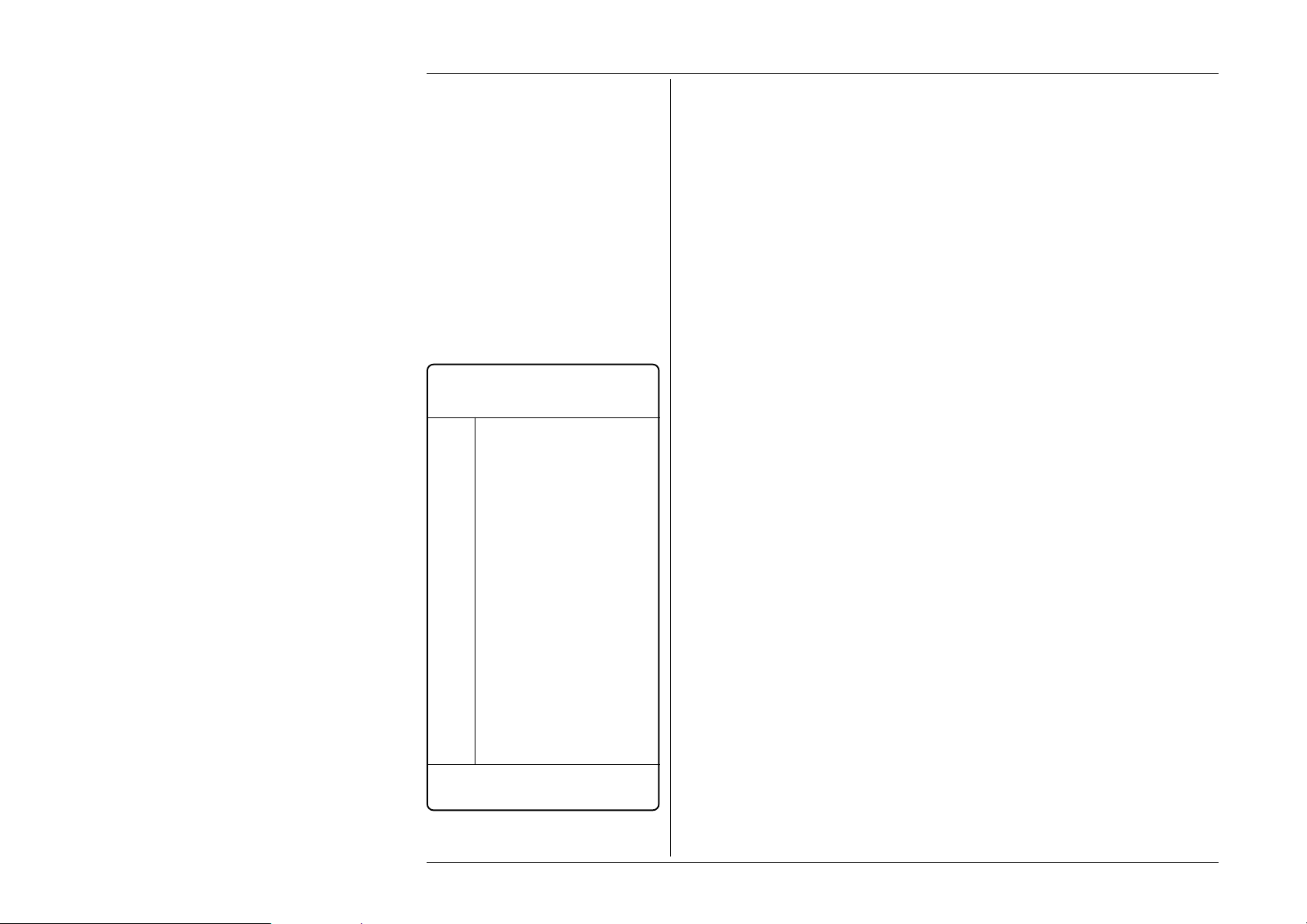
Table 6.1
IEEE 488.1 Interface Capability
6.3 Introduction
This first part of Section 5 gives the information necessary to put the 9100 into operation
on the IEEE 488 bus. For more detailed information, refer to the standard specification
in the publications ANSI/IEEE Std. 488.1-1987 and IEEE Std. 488.2-1988.
6.3.1 Interface Capability
6.3.1.1 IEEE Standards 488.1 and 488.2
The 9100 conforms to the Standard Specification IEEE 488.1-1987: ‘IEEE Standard
Digital Interface for Programmable Instrumentation’, and to IEEE 488.2-1988: ‘Codes,
Formats, Protocols and Common Commands’.
6.3.1.2 The 9100 in IEEE 488.2 Terminology
In IEEE 488.2 terminology the 9100 is a device containing a system interface. It can be
connected to a system via its system bus and set into programmed communication with
other bus-connected devices under the direction of a system controller.
6.3.1.3 Programming Options
The instrument can be programmed via the IEEE Interface, to:
• Change its operating state (Function, Range, etc).
• Transmit its own status data over the bus.
• Request service from the system controller.
6.3.1.4 Capability Codes
To conform to the IEEE 488.1 standard specification, it is not essential for a device to
encompass the full range of bus capabilities. For IEEE 488.2, the device must conform
exactly to a specific subset of IEEE 488.1, with a minimal choice of optional capabilities.
The IEEE 488.1 document describes and codes the standard bus features, for manufacturers
to give brief coded descriptions of their own interfaces’ overall capability. For IEEE
488.2, this description is required to be part of the device documentation. A code string
is often printed on the product itself.
The codes which apply to the 9100 are given in table 6.1, together with short descriptions.
They also appear on the rear of the instrument next to the interface connector. These codes
conform to the capabilities required by IEEE 488.2.
Appendix C of the IEEE 488.1 document contains a fuller description of each code.
6-4 Section 6: 9100 System Operation — SCPI Language
Page 11

6.3.1.5 Bus Addresses
When an IEEE 488 system comprises several instruments, a unique ‘Address’ is assigned
to each to enable the controller to communicate with them individually.
Only one address is required for the 9100. The application program adds information to
it to define ‘talk’ or ‘listen’. The method of setting the address, and the point at which the
user-initiated address is recognized by the 9100, is given in Sub-Section 6.4.1.
The 9100 has a single primary address, which can be set by the user to any value within
the range from 0 to 30 inclusive. It cannot be made to respond to any address outside this
range. Secondary addressing is not available.
6.3.1.6 Limited Access
The 9100 has five main modes, which are described briefly in Volume 1 of this Handbook,
Section 1, Sub-section 1.2.2. Remote operation is available only subject to the following
limitations:
• Procedure Mode
When the 9100 is in Procedure Mode, it is driven essentially from the front panel.
Remote Operation will not be allowed in this mode.
N.B. The 9100 can be powered up in either Manual mode or Procedure mode, as set
locally in Configuration mode.
• Manual Mode
Remote operation is available for each Manual mode function, but for ease of
programming, some remote commands do not mirror front panel operations exactly.
• Configuration Mode
Remote operation is not available, and configuration commands have not been
included in the SCPI command set for the 9100.
• Calibration Mode
Remote operation is available, but refer to Sub-section 6.6.2 for details of entry
protection.
• Test Mode
Remote operation is not available, but the 'Full' selftest can be initiated by a SCPI
command. The 9100 will give a straight Pass/Fail response, but to investigate further,
it will be necessary to re-run the test in Test mode from the front panel.
Final Width = 215mm
Section 6: 9100 System Operation — SCPI Language 6-5
Page 12
Final Width = 215mm
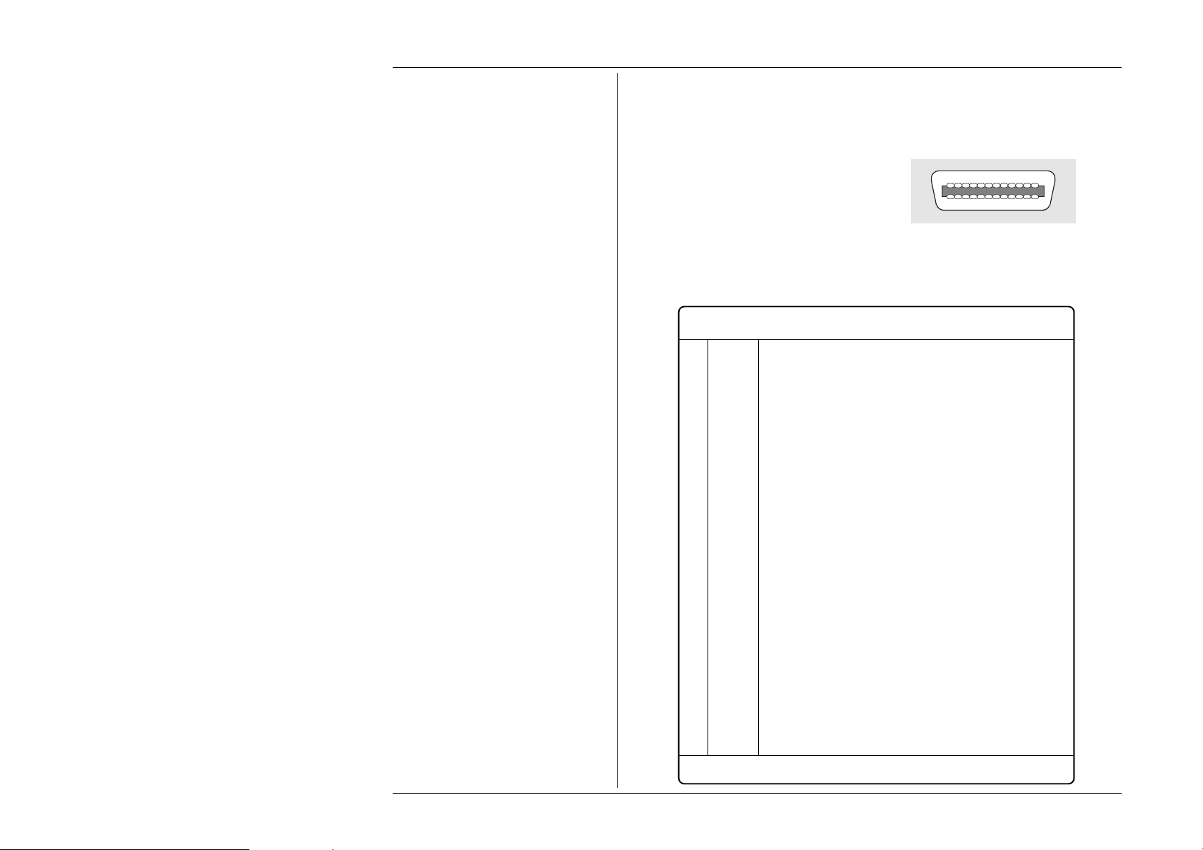
6.3.2 Interconnections
Instruments fitted with an IEEE 488
interface communicate with each other
through a standard set of interconnecting
cables, as specified in the IEEE 488.1
Standard document.
The IEEE-488 interface socket, J101, is
fitted on the rear panel. It accommodates
the specified connector, whose pin
designations are also standardized as
shown in Table 6.2
Pin
No. Name Description
1 DIO 1 Data Input/Output Line 1
2 DIO 2 Data Input/Output Line 2
3 DIO 3 Data Input/Output Line 3
4 DIO 4 Data Input/Output Line 4
5 EOI End or Identify
6 DAV Data Valid
7 NRFD Not Ready For Data
8 NDAC Not Data Accepted
9 IFC Interface Clear
10 SRQ Service Request
11 ATN Attention
12 SHIELD Screening on cable (connected to 9100 safety ground)
13 DIO 5 Data Input/Output Line 5
14 DIO 6 Data Input/Output Line 6
15 DIO 7 Data Input/Output Line 7
16 DIO 8 Data Input/Output Line 8
17 REN Remote Enable
18 GND 6 Gnd wire of DAV twisted pair
19 GND 7 Gnd wire of NRFD twisted pair
20 GND 8 Gnd wire of NDAC twisted pair
21 GND 9 Gnd wire of IFC twisted pair
22 GND 10 Gnd wire of SRQ twisted pair
23 GND 11 Gnd wire of ATN twisted pair
24 GND 9100 Logic Ground (internally connected to Safety Ground)
112
1324
Connector J101 - Pin Layout
Table 6.2 Connector J101 - Pin Designations
6-6 Section 6: 9100 System Operation — SCPI Language
Page 13

6.3.3 SCPI Programming Language
Standard Commands for Programmable Instruments (SCPI) is an instrument command
language which goes beyond IEEE 488.2 to address a wide variety of instrument
functions in a standard manner.
IEEE 488.2 defines sets of Mandatory Common Commands and Optional Common
Commands along with a method of Standard Status Reporting. The 9100 implementation
of SCPI language conforms with all IEEE-488.2 Mandatory Commands but not all
Optional Commands. It conforms with the SCPI-approved Status Reporting method.
Note: Commands in SCPI language, prefaced by an asterisk (eg: ∗CLS), are IEEE-488.2
standard-defined ‘Common’ commands.
Conformance of the 9100 remote programming commands to SCPI ensures that the 9100
has a high degree of consistency with other conforming instruments. For most specific
commands, such as those relating to frequency and voltage, the SCPI approved command
structure already exists and has been used wherever possible.
SCPI commands are easy to learn, self-explanatory and account for a wide variety of
usage skills. A summary of the 9100 commands is given on pages 6-2 and 6-3. The full
range of 9100 commands, with their actions and meanings in the 9100, is detailed in
alphabetical order in Sub-Section 6-6.
Final Width = 215mm
Section 6: 9100 System Operation — SCPI Language 6-7
Page 14
Final Width = 215mm
6.4 Using the 9100 in a System
6.4.1 Addressing the 9100
6.4.1.1 Accessing the Bus Address
The instrument address can only be set manually; using the Bus Address menu, which
is accessed via the Configuration menus.
N.B. A password is required for access to change the bus address.
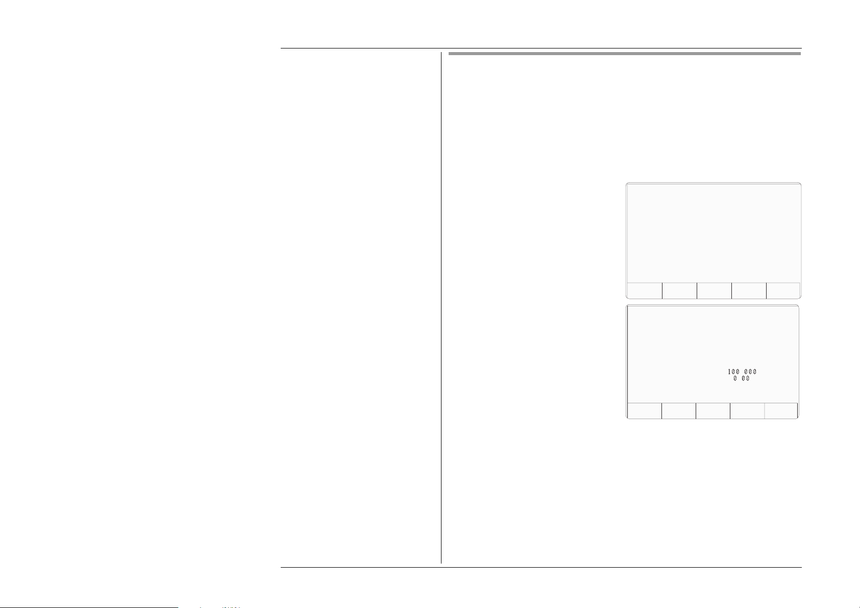
6.4.1.2 Select 'Configuration' Mode
1. Press the Mode key on the right of the
front panel to obtain the 'Mode
Selection' menu screen:
2. Press the CONFIG screen key at the
center of the bottom row to progress
into 'Configuration' mode. The 9100
will transfer to the open 'Configuration'
menu screen:
Mode Selection
Select required mode using softkeys
TODAYS DATE TIME
PROC MANUAL CONFIG CALIB TEST
Configuration
Ser. No. XXXXXX Rev. XXX
Present Settings:
Language English
Power-up mode Manual
Bus Address 1
Printer NONE
Results Card Disabled
Safety Voltage . V
Border Line 7 . %
Scope option Option 600
Crystal option High acc
TODAYS DATE TIME
MOREVIEW
6.4.1.3 Select 'MORE' Parameters
The bus address is one of the 'MORE' parameters. By trying to select 'MORE', the
'Configuration' password will be required.
Press the MORE screen key on the right of the bottom row. The 9100 will transfer
to the 'Password Entry' screen.
6-8 Section 6: 9100 System Operation — SCPI Language
Page 15
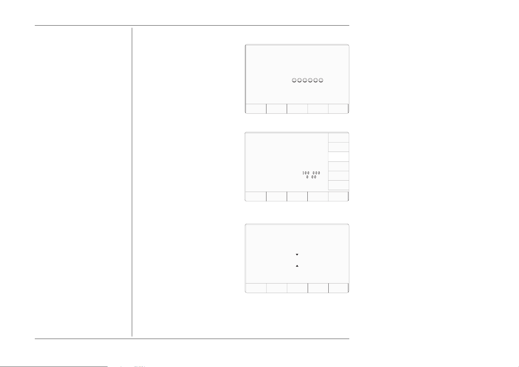
6.4.1.4 Enter Your Password
1. When you enter your password using
the alpha-numeric keyboard, security
icons will appear on the screen as you
type. Finally press the ↵ (return) key.
If the password is incorrect: an error
message will be given and the security
icons will be removed, enabling a new
attempt to enter the password.
The 'EXIT' screen key acts to escape,
back to the previous screen.
2. The correct password, followed by ↵,
will provide entry to the main
'Configuration' menu screen, which
shows the present settings of the
parameters which can be changed using
screen keys on this display:
3. In this case we are interested in 'BUS
ADDRESS'.
6.4.1.5 Change the Bus Address
Password Entry
For Configuration
Enter password :
TODAYS DATE TIME
EXIT
Configuration
Ser. No. XXXXXX Rev. XXX
Present Settings:
Language English
Power-up mode Manual
Bus Address 1
Printer NONE
Results Card Disabled
Safety Voltage . V
Border Line 7 . %
Scope option Option 600
Crystal option High acc
TODAYS DATE TIME
VOLTAGE
LIMIT
DATE
TIME
BORDER
LINE
SELECT
LANG
POWER
UP MODE
BUS
ADDRESS
PRINTER
RESULTS
CARD
CLEAR
USER
LIST
MORE
Final Width = 215mm
Note: Address Recognition
With an address selected in the range 0
to 30; control may be manual, or remote
as part of a system on the Bus. The
address must be the same as that used
in the controller program to activate
the 9100. The 9100 is always aware of
its stored address, responding to Talk
or Listen commands from the controller
at that address. When the address is
changed by the user, the 9100
recognizes its new address and ignores
its old address, as soon as it is stored by
the user pressing the EXIT key in the
Configuration — Bus Address menu.
1. For access from the 'Present Settings'
screen, press the BUS ADDRESS
screen key on the right. This action will
transfer to the 'Change the address'
screen:
The 9100 IEEE-488 bus address can be set
to any number within the range 0 to 30.
2. Use Digit edit or Direct edit to set the
required bus address number. If using
Direct edit, after typing the number
press the ↵ key.
3. Press EXIT to return to the 'Present
Settings' screen.
Section 6: 9100 System Operation — SCPI Language 6-9
Configuration
Change the address by using
digit or direct editing.
Bus address =
TODAYS DATE TIME
EXIT
22
Page 16

Final Width = 215mm
6.4.2 Operation via the IEEE-488 Interface
6.4.2.1 General
The power-up sequence is performed as in local operation. The 9100 can be programmed
to generate an SRQ at power-up, also preparing a status response for transmission to the
controller when interrogated by a subsequent serial poll.
6.4.2.2 Operating Conditions
When the 9100 is operating under the direction of the application program, there are two
main conditions, depending on whether the application program has set the 'REN'
management line 'true' or 'false':
1. REN True ('REN' line low):
The 9100 can be addressed and commanded if in either 'Manual' or 'Calibration' mode.
All access to front panel control will be removed, except for the bottom right screen
key, labelled 'Enable Local Usage'. The cursor controls will not be present.
If LLO (Local Lockout) has been sent with REN true, then the 'Enable Local Usage'
screen key will be inoperative. If LLO has not been sent, the 'Enable Local Usage'
screen key will return to local control as if REN were false (see 2 below).
The 9100 will act in response to valid commands, performing any changes in output,
etc. The display presentation will track the changes.
Remote control cannot command 'Configuration' mode or 'Procedure' mode. These
are Local Modes only. Remote control cannot break into locally-entered 'Configuration'
mode, 'Procedure' mode or 'Test' mode. However, 'Test' can be run remotely.
2. REN False ('REN' line high):
The 9100 will remain in Local Operation, but can be addressed and commanded,
while full access to front panel control is also retained.
The 9100 will act in response to the commands, performing any changes in output, etc.
These changes will occur rapidly enough for the only noticeable effect to be the
display presentation tracking the changes.
6.4.2.3 Programmed Transfer to Local Control (GTL or REN False)
The application program can switch the 9100 into ‘Local’ Control (by sending Command
GTL, or by setting the REN line false), permitting a user to take manual control from the
front panel.
The application program can regain ‘Remote’ control by sending the overriding command:
Listen Address with REN true (addressing the 9100 as a listener with the Remote Enable
management line true {Low}). This will re-impose remote control, unless the 9100 is in
Configuration, Procedure or Test Mode.
6-10 Section 6: 9100 System Operation — SCPI Language
Page 17

6.4.2.4 ‘Device Clear’
Either of the commands DCL or SDC will force the following instrument states:
• all IEEE 488 input and output buffers cleared;
• with 'IFC' (Interface Clear), any device-dependent message bus holdoffs cleared.
• the status byte is changed by clearing the MAV bit.
These commands will not:
• change any settings or stored data within the device except as listed above;
• interrupt analog output;
• interrupt or affect any functions of the device not associated with the IEEE 488
system;
6.4.2.5 Levels of Reset
Three levels of reset are defined for IEEE 488.2 application programs, a complete system
reset being accomplished by resetting at all three levels, in order, to every device. In other
circumstances they may be used individually or in combination:
IFC Bus initialization;
DCL Message exchange initialization;
∗RST Device initialization.
The effects of the ∗RST command are described in Appendix C to this section.
Final Width = 215mm
Section 6: 9100 System Operation — SCPI Language 6-11
Page 18
6.4.3 Message Exchange
6.4.3.1 IEEE 488.2 Model
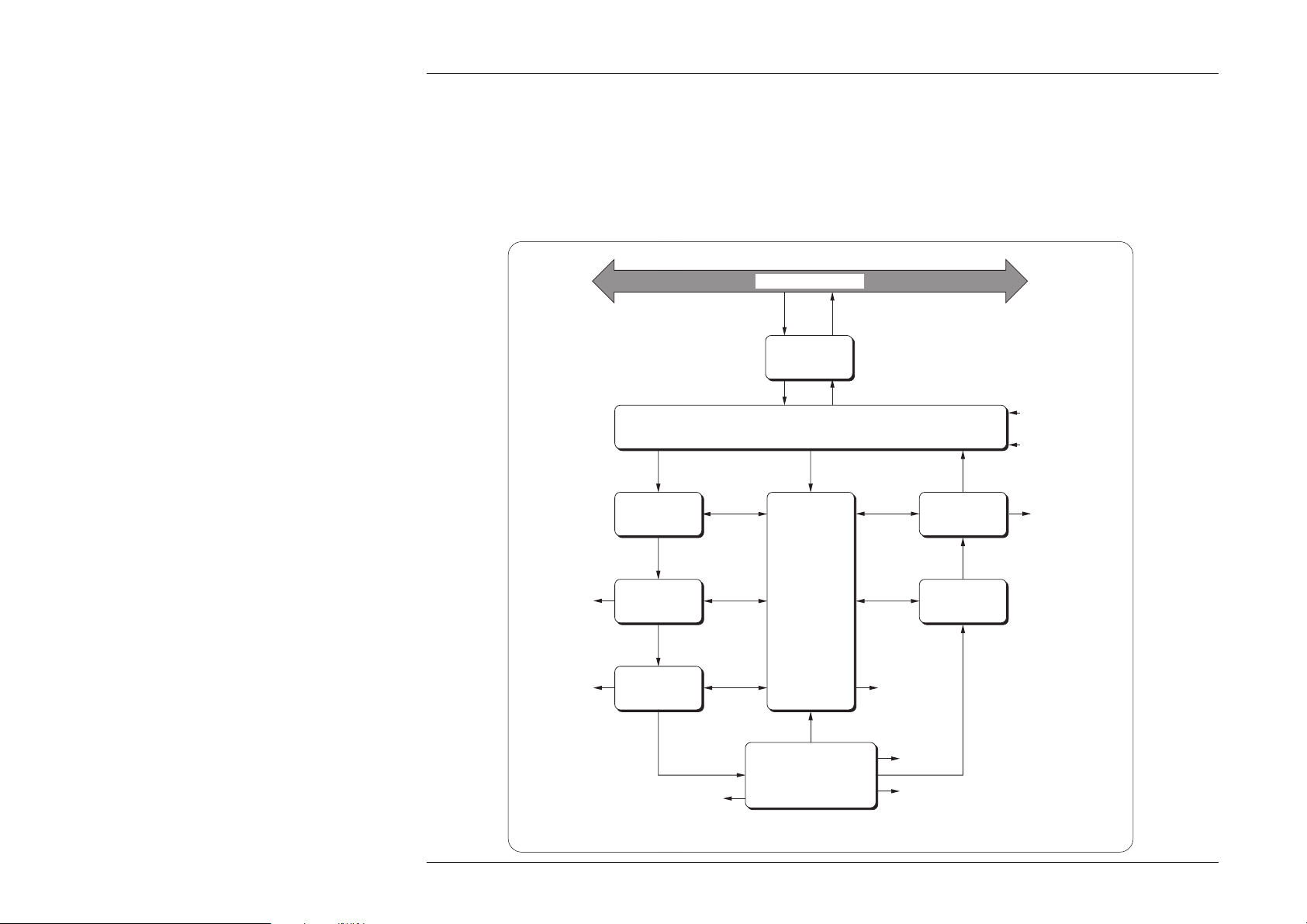
The IEEE 488.2 Standard document illustrates its Message Exchange Control Interface model at the detail level required by the
device designer. Much of the information at this level of interpretation (such as the details of the internal signal paths etc.) is
transparent to the application programmer. However, because each of the types of errors flagged in the Event Status Register is
related to a particular stage in the process, a simplified 9100 interface model can provide helpful background. This is shown below
in Fig. 6.1, together with brief descriptions of the actions of its functional blocks.
IEEE 488.1 bus
Bus
Messages
9100 Bus
Transmissions
Final Width = 215mm
General and Addressed
Bus Messages
Received
Message
Elements
Command
Errors
(CME bit)
Parsed
Message
Elements
Execution
Errors
(EXE bit)
Execution
Control
Executable
Message
Elements
Device-Dependent
Errors (DDE bit)
Input
Buffer
Parser
IEEE-488-1
Bus Interface
Input/Output Control
Message
Exchange
Control
9100 Functions
and Facilities
Filter out bus management and
configuration commands
Requested
Bus Messages
Output
Queue
Response
Message
Elements
Response
Formatter
Query Errors
(QYE bit)
Power On
(PON bit)
(URQ bit)
Response
Data
Status Byte
(STB)
RQS bit state
for Status Byte
Message
Available
(MAV bit)
Fig. 6.1 9100 Message Exchange Model
6-12 Section 6: 9100 System Operation — SCPI Language
Page 19

Note: Coupled Commands
Coupled commands are best described by
an example:
In Section 7, on pages 7-5 and 7-10, the
'Volt-Hz' and 'Amp-Hz' profiles are given.
In the 9100, no AC output can be generated
whose product of amplitude and frequency
occurs outside the relevant profile.
With sequential execution of commands a
change in amplitude and frequency
(e.g.:VOLT 121;:FREQ 10E3 - a setting
within the profile) would cause an execution
error if the present frequency was 50kHz,
as the combination of 121V and 50kHz is
outside the profile
Such anomalies are overcome by defining
a coupling between commands which
allows the execution of the individual
components to be deferred until all
contiguous coupled commands in the same
group have been parsed and the validity of
the combination checked
Note that this does not require that all the
coupled components in a group must be
supplied for each new signal but that those
programmed will be correctly parsed.
Individual commands may be a member of
several coupled command groups. Refer to
Appendix A to this Section, page 6-A1, for
details of coupled groups.
6.4.3.2 9100 STATUS Subsystem
Input/Output Control transfers messages from the 9100 output queue to the system bus;
and conversely from the bus to either the input buffer, or other predetermined destinations
within the device interface. It receives the Status Byte from the status reporting system,
as well as the state of the Request Service bit which it imposes on bit 6 of the Status Byte
response. Bit 6 reflects the ‘Request Service state true’ condition of the interface.
6.4.3.3 Incoming Commands and Queries
The Input Buffer is a first in - first out queue, which has a maximum capacity of 128 bytes
(characters). Each incoming character in the I/O Control generates an interrupt to the
instrument processor which places it in the Input Buffer for examination by the Parser.
The characters are removed from the buffer and translated with appropriate levels of
syntax checking. If the rate of programming is too fast for the Parser or Execution
Control, the buffer will progressively fill up. When the buffer is full, the handshake is
held.
The Parser checks each incoming character and its message context for correct Standard-
defined generic syntax, and correct device-defined syntax. Offending syntax is reported
as a Command Error, by setting true bit 5 (CME) of the Standard-defined Event Status
register (refer to Sub-Section 6.5 ‘Retrieval of Device Status Information’).
Execution Control receives successfully parsed messages, and assesses whether they
can be executed, given the currently-programmed state of the 9100 functions and
facilities. If a message is not viable then an Execution Error is reported, by setting true
bit 4 (EXE) of the Standard-defined Event Status register. Viable messages are executed
in order, altering the 9100 functions, facilities etc. Execution does not ‘overlap’
commands; instead, the 9100 Execution Control processes all commands or coupled
groups of commands (see Note in left column) ‘sequentially’ (ie. waits for actions
resulting from the previous command to complete before executing the next).
6.4.3.4 9100 Functions and Facilities
The 9100 Functions and Facilities block contains all the device-specific functions and
features of the 9100, accepting Executable Message Elements from Execution Control
and performing the associated operations. It responds to any of the elements which are
valid Query Requests (both IEEE 488.2 Common Query Commands and 9100 Devicespecific Commands) by sending any required Response Data to the Response Formatter
(after carrying out the assigned internal operations).
Device-dependent errors are detected in this block. Bit 3 (DDE) of the Standard Event
Status register is set true when an internal operating fault is detected. Each reportable
error number is appended to the Error Queue as the error occurs.
Final Width = 215mm
Section 6: 9100 System Operation — SCPI Language 6-13
Page 20

Final Width = 215mm
6.4.3.5 Outgoing Responses
The Response Formatter derives its information from Response Data (being supplied
by the Functions and Facilities block) and valid Query Requests. From these it builds
Response Message Elements, which are placed as a Response Message into the Output
Queue.
The Output Queue acts as a store for outgoing messages until they are read over the
system bus by the application program. For as long as the output queue holds one or more
bytes, it reports the fact by setting true bit 4 (Message Available - MAV) of the Status Byte
register. Bit 4 is set false when the output queue is empty (refer to Sub-Section 6.5
‘Retrieval of Device Status Information’).
6.4.3.6 ‘Query Error’
This is an indication that the application program is following an inappropriate message
exchange protocol, resulting in the Interrupted, Unterminated or Deadlocked condition:
Refer to 'Bit 2' in paras 6.5.3.5.
The Standard document defines the 9100’s response, part of which is to set true bit 2
(QYE) of the Standard-defined Event Status register.
6.4.4 Request Service (RQS)
6.4.4.1 Reasons for Requesting Service
There are two main reasons for the application program to request service from the
controller:
• When the 9100 message exchange interface is programmed to report a system
programming error;
• When the 9100 is programmed to report significant events by RQS.
The significant events vary between types of devices; thus there is a class of events which
are known as ‘Device-Specific’. These are determined by the device designer.
6.4.4.2 RQS in the IEEE 488.2 Model
The application programmer can enable or disable the event(s) which are required to
originate an RQS at particular stages of the application program. The IEEE 488.2 model
is extended to incorporate a flexible SCPI status reporting structure in which the
requirements of the device designer and application programmer are both met.
This structure is described in Sub-Section 6.5, dealing with ‘Retrieval of Device Status
Information’.
6-14 Section 6: 9100 System Operation — SCPI Language
Page 21

6.5 Retrieval of Device Status Information
6.5.1 General
For any remotely-operated system, the provision of up-to-date information about the
performance of the system is of major importance. In the case of systems which operate
under automatic control, the controller requires the necessary feedback to enable it to
progress the task; any break in the continuity of the process can have serious results.
When developing an application program, the programmer needs to test and revise it,
knowing its effects. Confidence that the program elements are couched in the correct
grammar and syntax (and that the program commands and queries are thus being accepted
and acted upon), helps to reduce the number of iterations needed to confirm and develop
the viability of the whole program. So any assistance which can be given in closing the
information loop must benefit both program compilation and subsequent use.
Such information is given in the following pages.
Final Width = 215mm
Section 6: 9100 System Operation — SCPI Language 6-15
Page 22
Final Width = 215mm
SCPI Status Structure Registers
Summary Bit — OSS
Operation
Status
Register
bit 15
bit 14
Not Used
in 9100
PRETESTING
TESTING
Not Used
in 9100
CALIBRATING
Not Used
in 9100
INV OHM CURR2
INV OHM CURR1
Not Used
in 9100
TEMPerature
Not Used
in 9100
bit 13
bit 12
bit 11
bit 10
bit 9
bit 8
bit 7
bit 6
bit 5
bit 4
bit 3
bit 2
bit 1
bit 0
OPERation:
OPERation:
EVENt ?
Summary Bit — QSS
Questionable
Status
Register
bit 15
bit 14
bit 13
bit 12
bit 11
bit 10
bit 9
bit 8
bit 7
bit 6
bit 5
bit 4
bit 3
bit 2
bit 1
bit 0
ENABle ?
Operation Status
Enable Register
OPERation:
ENABle <DNPD>
Questionable
Status
Enable Register
IEEE 488.2 Status Structure Registers
Summary Bit — ESB
Standard-
Defined
Event Status
Power On
Not Used
in 9100
Command Error
Execution Error
Device-Dependent Error
Query Error
Not Used
in 9100
Operation Complete
Register
bit 7
PON
bit 6
URQ
bit 5
CME
bit 4
EXE
bit 3
DDE
bit 2
QYE
bit 1
RQC
bit 0
OPC
Enable Register
Master Status Summary Bit
Event Status
Request for Service Bit
Not Used
in 9100
Message Available Bit — MAV
(True if one or more
messages are present in
the Output Queue)
Status Byte
Register
bit 7
OSS
bit 6
MSS RQS
bit 5
ESB
bit 4
MAV
bit 3
QSS
bit 2
bit 1
bit 0
∗ STB? ∗ SRE?
Service Request
Enable Register
∗ SRE
phs Nrf
FIFO
Output
Queue
QUEStionable:
QUEStionable:
EVENt ?
ENABle ?
QUEStionable:
ENABle <DNPD>
∗ ESR? ∗ ESE?
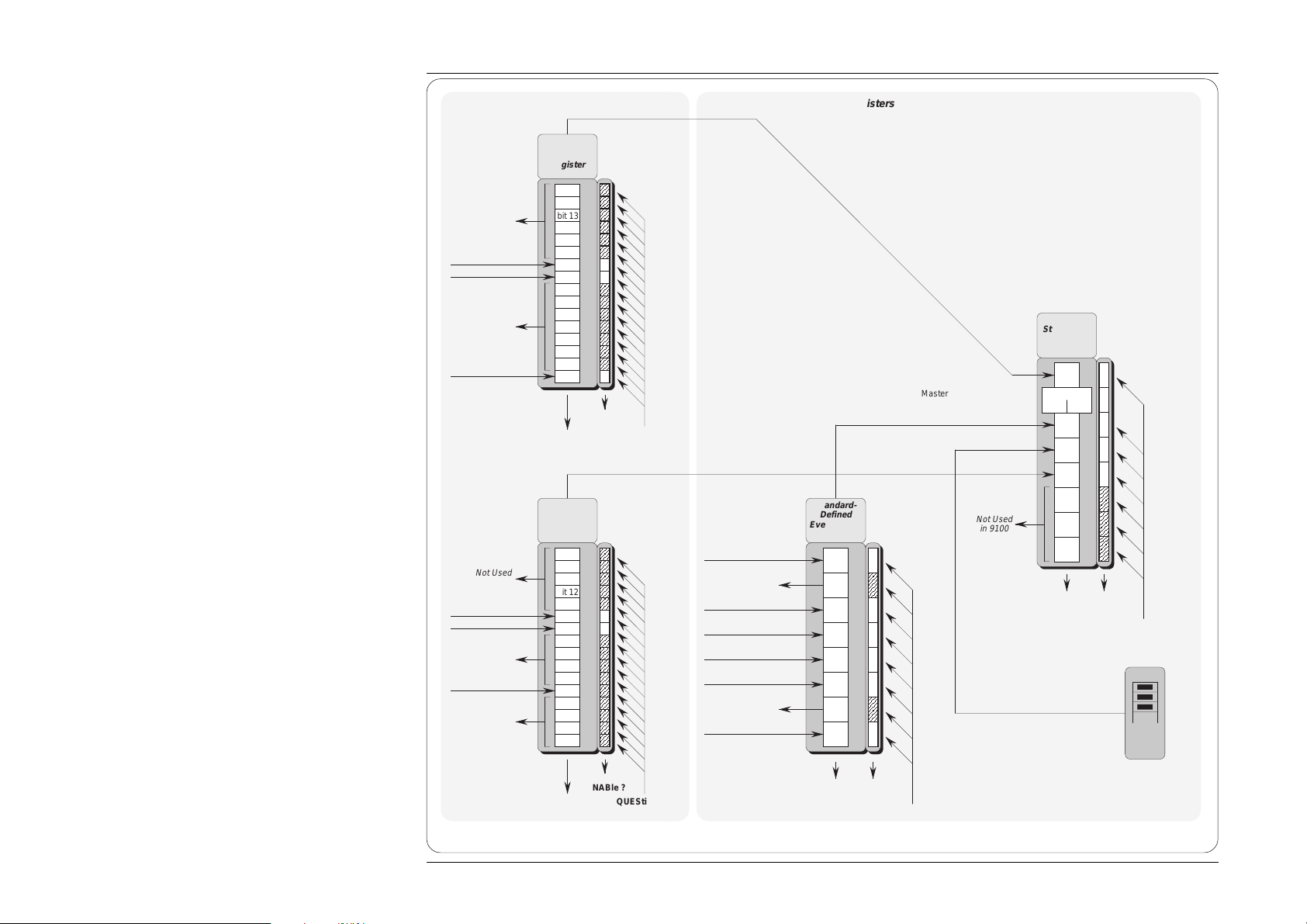
Fig. 6.2 9100 Status Reporting Structure
6-16 Section 6: 9100 System Operation — SCPI Language
∗ ESE
phs Nrf
Page 23

6.5.2 IEEE-488 and SCPI Standard-Defined Features (Fig. 6.2)
Two main categories of information are provided: 'Status Summary' information, and 'Event Register' conditions.
6.5.2.1 Status Summary Information and SRQ
The Status Byte consists of four 'summary' bits which notify
events in the 8-bit latched IEEE-488.2-defined ‘Event Status
Register’ (ESB), the two 16-bit latched SCPI-defined registers
(OSS & QSS), and the Output Queue (MAV). Whenever one of
these summary bits is enabled and set true, the Status Byte
summary bit (MSS) is also set true. The buffered bit 'RQS'
follows true when MSS goes true, and will set the IEEE-488
SRQ line true (Note that in Fig 6.2 no arrow points at bit 6 of the
Service Request Enable Register — bit 6 is always enabled).
A subsequent serial poll by the Application Program will
discover that the 9100 was the requesting device (while resetting
RQS false again, MSS remaining true), and which of the
summary bits is true. The ∗STB? command is an equivalent
command to serial poll, where serial poll is not available.
6.5.2.2 Event Register Conditions
The Status Byte summary bits direct the application program
down the structure towards causal events.
ESB and MAV are standard IEEE-488 features, described in
detail in Sub-Section 6.5.3.
OSS and QSS are features of the SCPI structure, described in
Sub-Section 6.5.4.
6.5.2.3 Access via the Application Program
Referring to Fig. 6.2, take as an example the main Event Status
register:
Enabling the Events
The main Standard-Defined Event Status Register' has a
second 'Event Status Enable Register'. A program command
(∗ESE phs Nrf) can be used to set the state of the bits in the
Enable register. This enables or disables the events which
will set the main register's summary bit true.
Reading the Enable Register
A 'query' command (*ESE?) permits the application program
to read the state of the Enable register, and hence find out
which events are enabled to be reported.
Reading the Main Register
Another 'query' command (*ESR?) reads the state of the
main Standard-Defined register, to discover which event
has occurred (i.e. has caused the summary bit to be set true).
Reading this register clears all its bits.
Reporting the Event
If an event is to be reported via the SRQ, its corresponding
enable bit will have been set true, (using the number Nrf).
Each bit in the Standard-Defined register remains in false
condition unless its assigned event occurs, when its condition
changes to true and remains true until cleared by ∗ESR? or
∗CLS. This causes the register's summary bit in the Status
Byte also to be set true. If this bit is enabled, then the Status
Byte bit 6 (MSS/RQS) will be set true, and the 9100 will set
the IEEE-488 bus SRQ line true.
SCPI Status Registers
The two SCPI Status registers operate in the same way, using
the appropriate program commands to set the enable registers,
and query commands to discover the condition of the registers.
Subsequent Action
Thus the application programmer can enable any assigned event
to cause an SRQ, or not. The controller can be programmed to
read the Status Byte, using a serial poll to read the Status Byte
register and the true summary bit (ESB, OSS, QSS or MAV).
The application program then investigates the appropriate event
structure until the causal event is discovered. The detail for each
register is expanded in the following paragraphs, and in the
command descriptions.
Final Width = 215mm
Section 6: 9100 System Operation — SCPI Language 6-17
Page 24

Final Width = 215mm
6.5.3 9100 Status Reporting - IEEE-488.2 Basics
6.5.3.1 IEEE 488.2 Model
This develops the IEEE 488.1 model into an extended structure with more definite rules.
These rules invoke the use of standard ‘Common’ messages and provide for devicedependent messages. A feature of the structure is the use of ‘Event’ registers, each with
its own enabling register as shown in Fig. 6.2.
6.5.3.2 9100 Model Structure
The IEEE 488.2 Standard provides for an extensive hierarchical structure with the Status
Byte at the apex, defining its bits 4, 5 and 6 and their use as summaries of a Standarddefined event structure, which must be included if the device is to claim conformance with
the Standard. The 9100 employs these bits as defined in the Standard.
Bits 0, 1, 2 and 3 and 7 are available to the device designer; only bits 3 and 7 are used in
the 9100, and these are as defined by the SCPI standard.
It must be recognized by the application programmer that whenever the application
program reads the Status Byte, it can only receive summaries of types of events, and
further query messages will be needed to probe the details relating to the events
themselves. For example: a further byte is used to expand on the summary at bit 5 of the
Status Byte.
6.5.3.3 Status Byte Register
In this structure the Status Byte is held in the ‘Status Byte Register’; the bits being
allocated as follows:
Bits: 0 (DIO1), 1 (DIO2) and 2 (DIO3) are not used in the 9100 status byte. They are
always false.
Bit 3 (DIO4) SCPI-defined Questionable Status Summary Bit (QSS)
Summarizes the state of the ‘Questionable Status data’, held in the ‘Questionable Status
register’ (QSR), whose bits represent SCPI-defined and device-dependent conditions in
the 9100. The QSS bit is true when the data in the QSR contains one or more enabled bits
which are true; or false when all the enabled bits in the byte are false. The QSR and its
data are defined by the SCPI Standard; they are described in Sub-Section 6.5.4.
Bit 4 (DIO5) IEEE 488.2-defined Message Available Bit (MAV)
The MAV bit helps to synchronize information exchange with the controller. It is true
when a message is placed in the Output Queue; or false when the Output Queue is empty.
The common command ∗CLS can clear the Output Queue, and the MAV bit 4 of the Status
Byte Register; providing it is sent immediately following a ‘Program Message Terminator’.
6-18 Section 6: 9100 System Operation — SCPI Language
Page 25

Bit 5 (DIO6) IEEE 488.2-defined Standard Event Summary Bit (ESB)
Summarizes the state of the ‘Event Status byte’, held in the ‘Event Status register’ (ESR),
whose bits represent IEEE 488.2-defined conditions in the device. The ESB bit is true
when the byte in the ESR contains one or more enabled bits which are true; or false when
all the enabled bits in the byte are false.
Bit 6 (DIO7) is the Master Status Summary Message (MSS bit), and is set true if one
of the bits 0 to 5 or bit 7 is true (bits 0, 1 and 2 are always false in the 9100).
Bit 7 (DIO4) SCPI-defined Operation Status Summary Bit (QSS)
Summarizes the state of the ‘Operation Status data’, held in the ‘Operation Status register’
(OSR), whose bits represent processes in progress in the 9100. The OSS bit is true when
the data in the OSR contains one or more enabled bits which are true; or false when all
the enabled bits in the byte are false. The OSR is described in Sub-Section 6.5.4.
Reading the Status Byte Register
∗STB?
The common query: ∗STB? reads the binary number in the Status Byte register. The
response is in the form of a decimal number which is the sum of the binary weighted values
in the enabled bits of the register. In the 9100, the binary-weighted values of bits 0, 1 and
2 are always zero.
6.5.3.4 Service Request Enable Register
The SRE register is a means for the application program to select, by enabling individual
Status Byte summary bits, those types of events which are to cause the 9100 to originate
an RQS. It contains a user-modifiable image of the Status Byte, whereby each true bit
acts to enable its corresponding bit in the Status Byte.
Bit Selector: ∗SRE phs Nrf
The common program command: ∗SRE phs Nrf performs the selection, where Nrf is a
decimal numeric, whose binary decode is the required bit-pattern in the enabling byte.
For example:
If an RQS is required only when a Standard-defined event occurs and when a message
is available in the output queue, then Nrf should be set to 48. The binary decode is
00110000 so bit 4 or bit 5, when true, will generate an RQS; but with this decode, even
if bit 3 is true, no RQS will result. The 9100 always sets false the Status Byte bits 0,
1 and 2, so they can never originate an RQS whether enabled or not.
Reading the Service Request Enable Register
The common query: ∗SRE? reads the binary number in the SRE register. The response
is in the form of a decimal number which is the sum of the binary-weighted values in the
register. The binary-weighted values of bits 0, 1 and 2 will always be zero.
Final Width = 215mm
Section 6: 9100 System Operation — SCPI Language 6-19
Page 26

Final Width = 215mm
Note about the ERROR Queue
The Error Queue is a sequential
memory stack. Each reportable error
has been given a listed number and
explanatory message, which are entered
into the error queue as the error occurs.
The queue is read destructively as a
First-In/First-Out stack, using the query
command SYSTem ERRor? to obtain
a code number and message.
Repeated use of the query SYSTem
ERRor? will read successive DeviceDependent, Command and Execution
errors until the queue is empty, when
the 'Empty' message (0,"No error")
will be returned.
It would be good practice to repeatedly
read the Error Queue until the 'Empty'
message is returned.
The common command ∗CLS clears
the queue.
6.5.3.5 IEEE 488.2-defined Event Status Register
The ‘Event Status Register’ holds the Event Status Byte, consisting of event bits, each of
which directs attention to particular information. All bits are ‘sticky’; ie. once true,
cannot return to false until the register is cleared. This occurs automatically when it is read
by the query: ∗ESR?. The common command ∗CLS clears the Event Status Register and
associated error queue, but not the Event Status Enable Register.
Note that because the bits are 'sticky', it is necessary to read the appropriate subordinate
register of the status structure in order to clear its bits and allow a new event from the same
source to be reported.
The ‘Event Status Register’ bits are named in mnemonic form as follows:
Bit 0 Operation Complete (OPC)
This bit is true only if ∗OPC has been programmed and all selected pending operations
are complete. As the 9100 operates in serial mode, its usefulness is limited to registering
the completion of long operations, such as self-test.
Bit 1 Request Control (RQC)
This bit is not used in the 9100. It is always set false.
Bit 2 Query Error (QYE)
QYE true indicates that the application program is following an inappropriate message
exchange protocol, resulting in the following situations:
• Interrupted Condition. When the 9100 has not finished outputting its Response
Message to a Program Query, and is interrupted by a new Program Message.
• Unterminated Condition. When the application program attempts to read a Response
Message from the 9100 without having first sent the complete Query Message
(including the Program Message Terminator) to the instrument.
• Deadlocked Condition. When the input and output buffers are filled, with the parser
and the execution control blocked.
Bit 3 Device Dependent Error (DDE)
DDE is set true when an internal operating fault is detected, and the appropriate error
message is added to the Error Queue. See the 'Note about the Error Queue' in the previous
column.
Bit 4 Execution Error (EXE)
An execution error is generated if the received command cannot be executed, owing to
the device state or the command parameter being out of bounds. The appropriate error
message is added to the Error Queue. See the 'Note about the Error Queue' in the previous
column.
6-20 Section 6: 9100 System Operation — SCPI Language
Page 27

Bit 5 Command Error (CME)
CME occurs when a received bus command does not satisfy the IEEE 488.2 generic
syntax or the device command syntax programmed into the instrument interface’s parser,
and so is not recognized as a valid command. The appropriate error message is added to
the Error Queue. See the 'Note about the Error Queue' on the previous page.
Bit 6 User Request (URQ)
This bit is not used in the 9100. It is always set false.
Bit 7 9100 Power Supply On (PON)
This bit is set true only when the Line Power has just been switched on to the 9100, the
subsequent Power-up Selftest has been completed successfully, and the 9100 defaults
into Manual mode at Power-on. (If the Power-on default is Procedure mode, remote
operation is not available. If the selftest is unsuccessful, the 9100 will report the fact in
Test mode, which also does not permit remote operation).
Whether or not an SRQ is generated by setting bit 7 true, depends on the previouslyprogrammed ‘Power On Status Clear’ message ∗PSC phs Nrf:
• For an Nrf of 1, the Event Status Enable register would have been cleared at power on,
so PON would not generate the ESB bit in the Status Byte register, and no SRQ would
occur at power on.
• If Nrf was zero, and the Event Status Enabling register bit 7 true, and the Service
Request Enabling register bit 5 true; a change from Power Off to Power On will
generate an SRQ. This is only possible because the enabling register conditions are
held in non-volatile memory, and restored at power on.
This facility is included to allow the application program to set up conditions so that a
momentary Power Off followed by reversion to Power On (which could upset the 9100
programming) will be reported by SRQ. To achieve this, the Event Status register bit 7
must be permanently true (by ∗ESE phs Nrf, where Nrf ≥ 128); the Status Byte Enable
register bit 5 must be set permanently true (by command ∗SRE phs Nrf, where Nrf lies
in one of the ranges 32-63, 96-127, 160-191, or 224-255); Power On Status Clear must
be disabled (by ∗PSC phs Nrf, where Nrf = 0); and the Event Status register must be read
destructively immediately following the Power On SRQ (by the common query ∗ESR?).
Final Width = 215mm
Continued Overleaf
Section 6: 9100 System Operation — SCPI Language 6-21
Page 28

Final Width = 215mm
6.5.3.6 Standard Event Status Enable Register
The ESE register is a means for the application program to select, from the positions of
the bits in the standard-defined Event Status Byte, those events which when true will set
the ESB bit true in the Status Byte. It contains a user-modifiable image of the standard
Event Status Byte, whereby each true bit acts to enable its corresponding bit in the
standard Event Status Byte.
Bit Selector: ∗ESE phs Nrf
The program command: ∗ESE phs Nrf performs the selection, where Nrf is a decimal
numeric, which when decoded into binary, produces the required bit-pattern in the
enabling byte.
For example:
If the ESB bit is required to be set true only when an execution or device-dependent
error occurs, then Nrf should be set to 24. The binary decode is 00011000 so bit 3 or
bit 4, when true, will set the ESB bit true; but when bits 0-2, or 5-7 are true, the ESB
bit will remain false.
Reading the Standard Event Enable Register
The common query: ∗ESE? reads the binary number in the ESE register. The response
is a decimal number which is the sum of the binary-weighted values in the register.
6.5.3.7 The Error Queue
As errors in the 9100 are detected, they are placed in a 'first in, first out' queue, called the
'Error Queue'. This queue conforms to the format described in the SCPI Command
Reference (Volume 2) Chapter 19, para 19.7, although errors only are detected. Three
kinds of errors are reported in the Error Queue, in the sequence that they are detected:
Command Errors, Execution Errors and Device-Specific errors
Reading the Error Queue
The queue is read destructively as described in the SCPI Command Reference, using the
query command SYSTem ERRor? to obtain a code number and error message. The query
SYSTem ERRor? can be used to read errors in the queue until it is empty, when the
message '0, No Error' will be returned.
6-22 Section 6: 9100 System Operation — SCPI Language
Page 29

6.5.4 9100 Status Reporting — SCPI Elements
6.5.4.1 General
In addition to IEEE 488.2 status reporting the 9100 implements the Operation and
Questionable Status registers with associated 'Condition', 'Event' and 'Enable' commands.
The extra status deals with current operation of the instrument and the quality of
operations.
The structure of these two registers is detailed in Fig. 6.2, together with the nature of the
reported events. Access to the registers is detailed in the STATus subsystem of Sub-
Section 6.6 of this handbook.
6.5.4.2 SCPI Status Registers
The SCPI states are divided into two groups, reporting from the Operation or Questionable
Status event register. Each Status register has its own 'Enable' register, which can be used
as a mask to enable bits in the event register itself, in a similar way to that set by the ∗ESE
command for the Standard Event status Register (ESR).
Each Status Register is associated with its own third 'Condition' register (not illustrated
in Fig. 6.2), in which the bits are not 'sticky', but are set and reset as the internal conditions
change.
Each Enable Register can be commanded to set its mask to enable selected bits in the
corresponding Event Register. All registers (Event, Enable and Condition) can be
interrogated by appropriate 'Queries' to divulge their bits' states.
Final Width = 215mm
6.5.4.3 Reportable SCPI States
Operation Status Event Register
The following 'sticky' bits are set by their associated conditions:
bit 0 CALIBRATING: a capacitance self-calibration operation is in progress.
bit 8 TESTING: the instrument is performing a self test.
bit 9 PRETESTING: the instrument is performing a power-up self test.
Questionable Status Event Register
The following 'sticky' bits are set by their associated conditions:
bit 4 TEMPerature: Thermocouple Reference Junction conditions doubtful
bit 9 INV OHM CURR 1: High/Low Current warning — outside specification
bit 10 INV OHM CURR 2: High/Low Current warning — change setting
Section 6: 9100 System Operation — SCPI Language 6-23
Page 30

Final Width = 215mm
6.6 9100 SCPI Language - Commands and Syntax
The command subsystems are placed in alphabetical order.
6.6.1 Introduction
This Sub-Section lists and describes the set of SCPI-compatible remote commands used to operate the 9100.
To provide familiar formatting for users who have previously used the SCPI reference documentation, the command descriptions
are dealt with in a similar manner. In particular, each sub-system's documentation starts with a short description, followed by a table
showing the complete set of commands in the sub-system; finally the effects of individual keywords and parameters are described.
Some extra identification of style and syntax is detailed in paras 6.6.1.1 and 6.6.1.2 to clarify shorthand meanings.
6.6.1.1 SCPI Syntax and Styles
Where possible the syntax and styles used in this section follow those defined by the SCPI consortium. The commands on the
following pages are broken into three columns; the KEYWORD, the PARAMETER FORM, and any NOTES.
The KEYWORD column provides the name of the command. The actual command consists of one or more keywords since SCPI
commands are based on a hierarchical structure, also known as the tree system.
Square brackets ( [ ] ) are used to enclose a keyword that is optional when programming the command; that is, the 9100 will process
the command to have the same effect whether the optional node is omitted by the programmer or not.
Letter case in tables is used to differentiate between the accepted shortform (upper case) and the long form (upper and lower case).
The PARAMETER FORM column indicates the number and order of parameter in a command and their legal value. Parameter
types are distinguished by enclosing the type in angle brackets ( < > ). If parameter form is enclosed by square brackets ( [ ] ) these
are then optional (care must be taken to ensure that optional parameters are consistent with the intention of the associated keywords).
The vertical bar ( | ) can be read as "or" and is used to separate alternative parameter options.
6.6.1.2 Legend
<DNPD> = Decimal Numeric Program Data, used to identify numerical information needed to set controls to required
values. The numbers should be in 'Nrf' form as described in the IEEE 488.2 Standard Specification.
<CPD> = Character Program Data. This normally represents alternative groups of unique 'literate' parameter names,
available for the same keyword. In the notation the set of alternatives will follow the <CPD> in the Parameter
Form column of the Sub-System table, enclosed in a pair of braces. For example, in the OUTPut sub-system,
the compound command header (keyword): OUTPut:COMPensation is followed by the parameter form
<CPD>{ON|OFF|0|1}. The <CPD> gives the denomination of 'Character' program data, and
{ON|OFF|0|1} gives the actual characters to be used to command each unique parameter.
<SPD> = String Program Data. This is a string of variable literate characters which will be recognized by the internal
9100 software. They are used for such inputs as passwords, serial numbers and date/time.
? = Indicate query commands with no associated command form, and no attached parameters.
(for example: CALibration:TRIGger?).
(?) = All commands which may include parameters in the command form, but also have an additional query form
without parameters.
(for example: OUTPut:COMPensation(?) <CPD>{HIGHi|LOWi})
The response from this query will be one of the parameters listed in association with the command.
6-24 Section 6: 9100 System Operation — SCPI Language
Page 31

6.6.2 CALibration Subsystem
This subsystem is used to calibrate the functions and hardware ranges of the 9100. This will correct for any system errors due to
drift or ageing effects.
Before any calibration can take place, two security levels must be set. First, there is a switch on the 9100 itself that must be set to
CAL ENABLE. Having done this, the calibration password command must be sent.
Once entered into Calibration mode, the commands present in the table at 6.6.2.1 are enabled.
6.6.2.1 CALibration Subsystem Table
Keyword Parameter Form Notes
CALibration
:SECure
:PASSword <SPD>
:EXIT [<SPD>,<CPD>{PRD7|PRD14|PRD30|PRD60}]
:TARGet <DNPD>,<DNPD>[,<DNPD>]
:TRIGger? [query only]
:SPECial? [query only]
:CJUNction? <DNPD>
6.6.2.2 CAL:SEC:PASS <SPD>
Purpose
This command is used to gain access to Calibration mode. The <SPD> must be the correct 'Calibration' password registered in the
9100 software. The calibration password can be changed only in Configuration mode from the 9100 front panel.
(Refer to Volume 1 of this User's Handbook, Section 3, Paras 3.3.2.11 and 3.2.2.22).
Final Width = 215mm
6.6.2.3 CAL:SEC:EXIT [<SPD>,<CPD>{PRD7|PRD14|PRD30|PRD60}]
Purpose
This command is used to switch off Calibration mode, cancelling any set CAL:TARG command and protecting the calibration by
positively disabling the calibration commands. Parameters in the command permit a user optionally to date-stamp the calibration,
record the next-due calibration date, and set up an advance warning for that calibration. Certain Functions are not available in
Calibration Mode (such as Conductance and Logic Pulses/Levels, for which calibration is not required). When finishing a
calibration procedure, it is necessary to exit from Calibration mode in order to access these functions.
• The <SPD> must be the due date of the next calibration for the 9100. It must conform to the format decided by the SYStem
FORmat <spd> command.
• In the <CPD>, PRDXX gives the required number of days advance warning of the cal due date.
(Refer to Section 10, Paras 10.3.6).
Section 6: 9100 System Operation — SCPI Language 6-25
Page 32

Final Width = 215mm
6.6.2 CALibration Subsystem (Contd.)
6.6.2.4 CAL:TARG <DNPD>,<DNPD>[,<DNPD>]
Purpose
For each calibration operation, the required calibration point (factor) must be targetted (Refer to Section 10, Paras 10.3.4). This
command permits the user to define three parameters associated with the calibration point in the current operation:
• The first <DNPD> is an integer from 1 to 6, allocated to the calibration point at which calibration is intended. This will be one
of those listed on the Calibration mode screen, in 'Target State', for the corresponding function and hardware range.
• The second <DNPD> is a value which will determine the required hardware range (amplitude) of the 9100 for that calibration
point.
• The third, optional, <DNPD> is a value which will determine the required hardware range (frequency) of the 9100 for that
calibration point.
For example when the 9100 is in AC Voltage at 30V 1kHz:
CAL:TARG 1 , 29.001 , 1.05
indicates that calibration of point 1 is required, at a voltage of 29.001V and a frequency of 1.05kHz.
Once a target has been set, the 9100 adjustment is restricted to values within the selected hardware voltage span and frequency band.
In order to release this restriction, one of the following commands must be sent:
TRIG? , EXIT or a new TARG command
Any error which occurs will also release the restriction.
6-26 Section 6: 9100 System Operation — SCPI Language
Page 33

6.6.2.5 CAL:TRIG?
Purpose
After the parameters are set for calibration at a single calibration point, this command initiates the internal calibration process.
Response
If the calibration operation is a success then the command returns a '0'. If the process fails for any reason, then a '1' is returned
and an error message is put in the error queue.
6.6.2.6 CAL:SPEC?
Purpose
This command characterizes the instrument's main Digital-to-Analog Converter.
Response
The process takes approximately 15 minutes to complete. If the characterization operation is a success then the command returns
a '0'. If the process fails for any reason, then a '1' is returned and an error message is put in the error queue.
6.6.2.7 CAL:CJUN? <dnpd>
Purpose
To obtain a calibration factor from an external measurement of the temperature of the reference junction in its pod, and a similar
internal measurement which is triggered by this command..
The <dnpd> MUST be supplied and should be the externally-measured temperature of the pod.
For successful calibration, the pod MUST be fitted and the external measurement MUST be supplied with the command.
This is the remote equivalent of the manual calibration of the pod detailed in Section 10, paras 10.2.5. Identification of the
association of the pod with a particular host 9100 unit should be recorded as for the manual case (paras 10.2.5.7)
Response
If the calibration operation is a success then the command returns a '0'. If the process fails for any reason, then a '1' is returned
and an error message is put in the error queue.
Section 6: 9100 System Operation — SCPI Language 6-27
Final Width = 215mm
Page 34

Final Width = 215mm
6.6.3 OUTPut Subsystem
This subsystem is used to select the output connections of the 9100, switch the output on and off, and switch the lead compensation
on and off.
6.6.3.1 OUTPut Subsystem Table
Keyword Parameter Form Notes
OUTPut
[:STATe](?) <CPD>{ON|OFF|0|1}
:COMPensation(?) <CPD>{ON|OFF|0|1}
:ISELection(?) <CPD>{HIGHi|HI50turn|HI10turn|LOWi}
6.6.3.2 OUTP[:STAT](?)<CPD>{ON|OFF|0|1}
Purpose
This command turns the 9100 output on and off.
• ON or 1 will set the output on
• OFF or 0 will set the output off
Response to Query Version
The 9100 will return ON if output is on, or OFF if output is off.
6.6.3.3 OUTP:COMP(?) <CPD>{ON|OFF|0|1}
Purpose
This command switches the output connections for 4-wire/2-wire in the impedance functions.
Impedance Functions:
Resistance, Conductance, Capacitance and PRT Temperature.
Response to Query Version
The 9100 will return ON if compensation is on (4-wire), or OFF if compensation is off (2-wire).
6-28 Section 6: 9100 System Operation — SCPI Language
Page 35

6.6.3.4 OUTP:ISEL(?) <CPD>{HIGHi|HI50|HI10|LOWi}
Purpose
The I+ Output in Current function can be passed out via the unguarded front panel I+ terminal, or on a guarded line (pin 8) through
the D-type socket ('Signal Output' J109) beneath the terminals. Pin 7 of J109 is connected to internal Guard shields for this purpose,
and is available for external guard connection. The return is always via the front panel main I- terminal.
The front panel I+ terminal can carry all DC currents and AC currents up to the maximum -20A to +20A output (refer to
Volume 1, Section 4, paras 4.5.5.3 for time limitations). Pin 8 of J109 is limited to -1A to +1A output.
OUTP:ISEL HIGH switches current outputs via the front panel I+ terminal,
OUTP:ISEL HI50 (Option 200) switches current outputs via the front panel I+ terminal, and provides equivalent
currents of ±(16.0A to 1000A) into the 50-turn current coil.
OUTP:ISEL HI10 (Option 200) switches current outputs via the front panel I+ terminal, and provides equivalent
currents of ±(3.2A to 200A) into the 10-turn current coil.
OUTP:ISEL LOW switches current outputs via J109 pin 8.
Response to Query Version
The 9100 will return HIGH/HI50/HI10/LOW to match the active programming parameter.
Final Width = 215mm
Section 6: 9100 System Operation — SCPI Language 6-29
Page 36

Final Width = 215mm
6.6.4 SOURce Subsystem
This subsystem is used to select the sources of 9100 output .
6.6.4.1 SOURce Subsystem Table
Keyword Parameter Form Notes
[SOURce]
:FUNCtion
[:SHAPe](?) <CPD>{DC|SINusoid|PULSe|SQUare|IMPulse|TRIangle|TRAPezoid|SYMSquare}
:VOLTage
[:LEVEl]
[:IMMediate]
[:AMPLitude](?) <DNPD>
:HIGH(?) <DNPD>
:LOW(?) <DNPD>
:CURRent
[:LEVEl]
[:IMMediate]
[:AMPLitude](?) <DNPD>
:RESistance
[:LEVEl]
[:IMMediate]
[:AMPLitude](?) <DNPD>
:UUT_I(?) <CPD>{LOW|HIGH|SUPer}
:CONDuctance
[:LEVEl]
[:IMMediate]
[:AMPLitude](?) <DNPD>
:UUT_I(?) <CPD>{LOW|HIGH|SUPer}
:CAPacitance
[:LEVEl]
[:IMMediate]
[:AMPLitude](?) <DNPD>
:UUT_I(?) <CPD>{LOW|SUPer}
:FREQuency
[:CW|FIXed](?) <DNPD>
:PHASe
[:ADJust](?) <DNPD>
:INPut
[:STATe](?) <CPD>{ON|OFF|0|1}
:OUTPut
[:STATe](?) <CPD>{ON|OFF|0|1}
6-30 Section 6: 9100 System Operation — SCPI Language
Page 37

[SOURce] (Contd)
:PULSe
:PERiod(?) <DNPD>
:WIDth(?) <DNPD>
:DCYCle(?) <DNPD>
:TEMPerature
:UNITs(?) <CPD>{C|CEL|F|FAH|K}
:SCALe(?) <CPD>{TS68|TS90}
:THERmocouple
[:LEVEl]
[:IMMediate]
[:AMPLitude](?) <DNPD>
:TYPE(?) <CPD>{B|C|E|J|K|N|R|S|T}
:PRT
[:LEVEl]
[:IMMediate]
[:AMPLitude](?) <DNPD>
:TYPE(?) <CPD>{PT385|PT392}
:NRESistance(?) <DNPD>
:UUT_I(?) <CPD>{LOW|HIGH|SUPer}
:CONTinuity
[:LEVEl]
[:IMMediate]
[:AMPLitude](?) <DNPD>
:TCURrent?
:INSulation
[:LEVEl]
[:IMMediate]
[:AMPLitude](?) <DNPD>
:UUT_I(?) <CPD>{HIGH|SUPer}
:TVOLtage?
:TCURrent?
Final Width = 215mm
Note to the [SOURce] Subsystem Table
Many optional keywords are included in the table; shown in square brackets, as required by the SCPI reference document. The
structure of the command set is such that in all cases, these optional keywords can be omitted.
Notes about Types of Command Separators
The [SOURce] subsystem has a complex tree structure. To clarify descriptions (as, for instance, in the table overleaf), examples
of branching are referred to the root. In the table, when transferring from, say, a VOLT HIGH command to a VOLT LOW command,
the command string returns to the root, so that rather than using the valid short-cut ; branching separator, it is shown as returning
to the root by a ;: separator.
This does not mean that valid short-cut 'program message unit' separators cannot be used, but merely that we are defining the
commands in full, to avoid confusion.
Section 6: 9100 System Operation — SCPI Language 6-31
Page 38

Final Width = 215mm
6.6.4.2 [SOUR]:FUNC[:SHAP](?) <CPD>{DC|SIN|PULS|SQU|IMP|TRI|TRAP|SYMS}
Purpose
Defines the waveshape of the required output. In certain cases this also steers the 9100 towards the required source. This is necessary
to select a 9100 source in a particular group, if the present 9100 source lies outside that group.
For example:
DC Voltage and DC Current are listed below in Group 2. To select either of these when neither of Group 2 is already selected,
then the command FUNC DC must be used before selecting Voltage or Current.
For those users who are familiar with local (front panel) operation of the 9100, the relationships between the local Function
selections and the corresponding remote commands are given in the following table:
[SOURce] Equivalent Remote Commands
Command 9100 Local
Group Function
1 a Resistance RES <DNPD>
b Conductance COND <DNPD>
c Capacitance CAP <DNPD>
d PRT Temp. TEMP:UNIT <CPD>;:TEMP:SCAL <CPD>;:TEMP:PRT <DNPD>
e T'coupl. Temp. TEMP:UNIT <CPD>;:TEMP:THER <DNPD>
2 a DC Voltage FUNC DC;:VOLT <DNPD>
b Logic Levels FUNC DC;:VOLT <DNPD>
c DC Current FUNC DC;:CURR <DNPD>
3 a AC Voltage FUNC {SIN|IMP|TRI|TRAP|SYMS};:VOLT <DNPD>;:FREQ <DNPD>
b AC Current FUNC {SIN|IMP|TRI|TRAP|SYMS};:CURR <DNPD>;:FREQ <DNPD>
4 Frequency FUNC SQU;:FREQ <DNPD>;:VOLT:HIGH <DNPD>;:VOLT:LOW <DNPD>
5 a Mark/Period FUNC PULS;:PULS:PER <DNPD>;:PULS:WID <DNPD>;:VOLT:HIGH <DNPD>;:VOLT:LOW <DNPD>
b % Duty FUNC PULS;:PULS:PER <DNPD>;:PULS:DCYC <DNPD>;:VOLT:HIGH <DNPD>;:VOLT:LOW <DNPD>
c Logic Pulses FUNC PULS;:PULS:PER <DNPD>;:PULS:WID <DNPD>;:VOLT:HIGH <DNPD>;:VOLT:LOW <DNPD>
or RES <DNPD>;:RES:UUT_I <CPD>
or COND <DNPD>;:COND:UUT_I <CPD>
or CAP <DNPD>;:COND:UUT_I <CPD>
or TEMP:UNIT <CPD>;:TEMP:SCAL <CPD>;:TEMP:PRT <DNPD>;:TEMP:PRT:UUT_I <CPD>
Notes:
Group 1 No FUNC steering is required. The Thermocouple Temperature source (1e) is included in the same group as the other (PRT) Temperature source.
Group 2 Steering command: FUNC DC is required. The remote equivalent of the local 'Logic Levels' Function uses the same commands as those for the
Group 3 Steering command: FUNC {SIN|IMP|TRI|TRAP|SYMS} is required. All alternative waveshapes shown are available only in this group.
Group 4 Steering command: FUNC SQU is required. 'Hz (Frequency)' employs a fixed 50% duty cycle.
Group 5 Steering command: FUNC PULS is required. All local equivalents include variable Mark/Period ratio.
main local DC Voltage Function.
N.B. The groups of [SOURce] commands, listed in the table, are not required by SCPI protocol, they have been devised
specially for this description only for clearer explanation.
6-32 Section 6: 9100 System Operation — SCPI Language
Page 39

Function Changes and Parameter Defaults
The values set as parameters are not retained on change of Equivalent Local Function (ELF), as indicated in the table.
When the 9100 is transferred from, say, ELF 1a to ELF 1b, the programmable parameters of ELF 1a will be set to default values,
and must be re-programmed on re-entry if different values are required.
<CPD>
The 'character program data' determines the waveshape of the output signal. It can be chosen from eight alternatives:
DC Determines that subsequent selection of VOLT or CURR will choose DC hardware for the output voltage or current.
Voltage or Current levels will be set subsequently using the VOLT <DNPD> or CURR <DNPD> commands.
SINusoid Subsequent selection of VOLT or CURR will choose AC hardware for the output voltage or current. Voltage or
Current RMS values will be set using the VOLT <DNPD> or CURR <DNPD> commands. Frequency values will
be set using the FREQ <DNPD> command.
SQUare Selects a pulsed voltage output, and determines that the mark/period ratio will be 0.5 for any related FREQ selection.
High and low voltage levels will be set to default values of +5V and 0V unless otherwise set using the VOLT HIGH
and VOLT LOW commands.
PULSe Selects a pulsed voltage output and determines that the mark/period ratio will be set by selections of PULS PER,
together with PULS WID or PULS DCYC. High and low voltage levels will be set to default values of +5V and
0V unless otherwise set using the VOLT HIGH and VOLT LOW commands.
IMPulse|TRIangle|TRAPezoid|SYMSquare
Subsequent selection of VOLT or CURR will choose AC hardware for the output voltage or current, with the
'Impulse, Triangular, Trapezoidal or Symmetrical Square' waveshape (refer to Volume 1, Section 4, paras 4.4.3.4 and
4.4.6.4). Voltage or Current RMS values will be set using the VOLT <DNPD> or CURR <DNPD> commands.
Frequency values will be set using the FREQ <DNPD> command.
Examples of using the FUNC element:
An example command message to select a Group 2 source of +10.5V from outside Group 2 would be:
FUNC DC;:VOLT 10.5
Alternatively, to select a Group 3 sinusoidal current source of 200mA at 1kHz from outside Group 3:
FUNC SIN;:CURR 200E-3;:FREQ 1E3
To select (from outside Group 5) a pulsed signal of period 200µs and duty cycle 60%, switching between +3.5V and -1.5V:
FUNC PULS;:PULS:PER 2E-4;:PULS:DCYC 60;:VOLT:HIGH 3.5;:VOLT:LOW -1.5
Sources in the Same Group
When selecting a source from within the same group as the previous [SOURce] command, it is not necessary to prefix the FUNC
command.
Response to Query Version
The 9100 will return the appropriate <CPD> from the selection {DC|SIN|PULS|SQU|IMP|TRI|TRAP|SYMS} which
represents the present source 'shape'. If the 9100 is programmed in one of the impedance functions (Group 1 in the table), then it
will return NONE.
Final Width = 215mm
Section 6: 9100 System Operation — SCPI Language 6-33
Page 40

6.6.4.3 [SOUR]:VOLT[:LEVE][:IMM][:AMPL](?) <DNPD>
Purpose
This command selects either DC or AC Voltage hardware, dependent upon the DC or SIN|IMP|TRI|TRAP|SYMS parameter
included in the most-recent FUNC command.
<DNPD>
The 'decimal numeric program data' is a number which sets the required output voltage, expressed in units of DC or RMS AC Volts.
It will automatically choose the 'best' hardware range for the defined voltage output. The 9100 will accept signed or unsigned
positive values for DC Voltage.
For details of local operation and parameter limitations, refer to Volume 1, Section 4, Sub-Sections 4.3 (DCV), 4.4 (ACV) or 4.17
(Logic Levels).
Response to Query Version
The instrument will return the present DC or AC voltage output value, dependent upon the DC or SIN|IMP|TRI|TRAP|SYMS
parameter implicit, or included, in the most-recent FUNC command. The returned number will be in standard scientific format
(for example: -200µV DC would be returned as -2.0E-4 — positive numbers, however, are unsigned)
Final Width = 215mm
6.6.4.4 [SOUR]:VOLT[:LEVE][:IMM]:HIGH(?) <DNPD>
Purpose
This command sets the high (most positive) voltage level for the square or pulsed voltage output , which has been selected by the
SQU or PULS parameter included in the most-recent FUNC command.
<DNPD>
The 'decimal numeric program data' is a number which sets the required high-level (most-positive) output voltage of the
programmed waveshape, expressed in units of Volts. It will automatically choose the 'best' hardware range for the defined voltage
output, in conjunction with the corresponding VOLT:LOW command for the same waveshape.
The value of <DNPD> cannot be equal to or more negative than that sent as the <DNPD> with the corresponding VOLT:LOW
command for the same waveshape. The 9100 will accept signed or unsigned positive values.
For details of local operation and parameter limitations, refer to Volume 1, Section 4, Sub-Sections 4.9 (Frequency), 4.10 (Mark/
Period), 4.11 (% Duty Cycle) or 4.16 (Logic Pulses).
Response to Query Version
The instrument will return the present high level voltage output value, associated with the SQU or PULS parameter implicit, or
included, in the query command. The returned number will be in standard scientific format (for example: +200mV would be
returned as 2.0E-1 — positive numbers are unsigned).
6-34 Section 6: 9100 System Operation — SCPI Language
Page 41

6.6.4.5 [SOUR]:VOLT[:LEVE][:IMM]:LOW(?) <DNPD>
Purpose
This command sets the low (most negative) voltage level for the square or pulsed voltage output , which has been selected by the
SQU or PULS parameter included in the most-recent FUNC command. Separate values are recorded for SQU and PULS
functions.
<DNPD>
The 'decimal numeric program data' is a number which sets the required low-level (most-negative) output voltage of the
programmed waveshape, expressed in units of Volts. It will automatically choose the 'best' hardware range for the defined voltage
output, in conjunction with the corresponding VOLT:HIGH command for the same waveshape.
The value of <DNPD> cannot be equal to or more positive than that sent as the <DNPD> with the corresponding VOLT:HIGH
command for the same waveshape. The 9100 will accept signed or unsigned positive values.
For details of local operation and parameter limitations, refer to Volume 1, Section 4, Sub-Sections 4.9 (Frequency), 4.10 (Mark/
Period), 4.11 (% Duty Cycle) or 4.16 (Logic Pulses).
Response to Query Version
The instrument will return the present low level voltage output value, associated with the SQU or PULS parameter implicit, or
included, in the query command. The returned number will be in standard scientific format (for example: +200mV would be
returned as 2.0E-1 — positive numbers are unsigned)
Final Width = 215mm
Section 6: 9100 System Operation — SCPI Language 6-35
Page 42

Final Width = 215mm
6.6.4.6 [SOUR]:CURR[:LEVE][:IMM][:AMPL](?) <DNPD>
Purpose
This command selects either DC or AC Current hardware, dependent upon the DC or SIN|IMP|TRI|TRAP|SYMS parameter
included in the most-recent FUNC command.
<DNPD>
The 'decimal numeric program data' is a number which sets the required output current, expressed in units of DC or RMS AC Amps.
It will automatically choose the 'best' hardware range for the defined current output. The 9100 will accept signed or unsigned
positive values for DC Current.
For details of local operation and parameter limitations, refer to Volume 1, Section 4, Sub-Sections 4.5 (DCI) or 4.6 (ACI).
Response to Query Version
The instrument will return the present DC or AC current output value, dependent upon the DC or SIN|IMP|TRI|TRAP|SYMS
parameter implicit, or included, in the most-recent FUNC command. The returned number will be in standard scientific format
(for example: -200µA DC would be returned as -2.0E-4 — positive numbers, however, are unsigned)
6-36 Section 6: 9100 System Operation — SCPI Language
Page 43

6.6.4.7 [SOUR]:RES[:LEVE][:IMM][:AMPL](?) <DNPD>
Purpose
This command selects Resistance hardware.
<DNPD>
The 'decimal numeric program data' is a number which sets the required output resistance, expressed in units of Ohms. It will
automatically choose the 'best' hardware range for the defined resistance output.
For details of local operation and parameter limitations, refer to Volume 1, Section 4, Sub-Section 4.7 (Resistance).
Response to Query Version
The instrument will return the present resistance output value. The returned number will be in standard scientific format (for
example: 200kΩ would be returned as 2.0E5)
6.6.4.8 [SOUR]:RES:UUT_I(?) <CPD>{LOW|HIGH|SUPer}
Purpose
In the synthesized resistance technology used in the 9100, the current sourced from the UUT must fall within certain spans of values
for each commanded resistance value. For UUTs producing source currents which are larger than the values in the 'Low' (default)
span, the greater current can be accommodated by selecting 'HIGH' or 'SUPER'.
The RES:UUT_I {LOW|HIGH|SUPer} command is used to switch between the three current configurations. There is no
default setting; refer to Volume 1 of this User's Handbook, Section 4, Sub-section 4.7, paras 4.7.5.7 for a description of UUT_I
current tracking during Resistance span changes.
<CPD>
The 'character program data' performs the required action. Refer to Volume 1, Section 4, paras 4.7.5.7, for a description of the current
limits and output voltage limitation.
• LOW will select the UUT source current 'Low' limits.
• HIGH will select the UUT source current 'High' limits.
• SUPer will select the UUT source current 'Super' limits.
Response to Query Version
The 9100 will return either LOW, HIGH or SUP, dependent on the active limits selection.
Final Width = 215mm
Section 6: 9100 System Operation — SCPI Language 6-37
Page 44

Final Width = 215mm
6.6.4.9 [SOUR]:COND[:LEVE][:IMM][:AMPL](?) <DNPD>
Purpose
This command selects Conductance hardware.
<DNPD>
The 'decimal numeric program data' is a number which sets the required output conductance, expressed in units of Siemens. It will
automatically choose the 'best' hardware range for the defined conductance output.
For details of local operation and parameter limitations, refer to Volume 1, Section 4, Sub-Section 4.8 (Conductance).
Response to Query Version
The instrument will return the present conductance output value. The returned number will be in standard scientific format (for
example: 200µS would be returned as 2.0E-4)
6.6.4.10 [SOUR]:COND:UUT_I(?) <CPD>{LOW|HIGH|SUPer}
Purpose
In the synthesized conductance technology used in the 9100, the current sourced from the UUT must fall within certain spans of
values for each commanded conductance value. For UUTs producing source currents which are larger than the values in the 'Low'
(default) span, the greater current can be accommodated by selecting 'HIGH' or 'SUPER'.
The COND:UUT_I {LOW|HIGH|SUPer} command is used to switch between the three current configurations. There is no
default setting; refer to Volume 1 of this User's Handbook, Section 4, Sub-section 4.8, paras 4.8.5.7 for a description of UUT_I
current tracking during Conductance span changes.
<CPD>
The 'character program data' performs the required action. Refer to Volume 1, Section 4, paras 4.8.5.7, for a description of the current
limits and output voltage limitation.
• LOW will select the UUT source current 'Low' limits.
• HIGH will select the UUT source current 'High' limits.
• SUPer will select the UUT source current 'Super' limits.
Response to Query Version
The 9100 will return either LOW, HIGH or SUP, dependent on the active limits selection.
6-38 Section 6: 9100 System Operation — SCPI Language
Page 45

6.6.4.11 [SOUR]:CAP[:LEVE][:IMM][:AMPL](?) <DNPD>
Purpose
This command selects Capacitance hardware.
<DNPD>
The 'decimal numeric program data' is a number which sets the required output capacitance, expressed in units of Farads. It will
automatically choose the 'best' hardware range for the defined capacitance output.
For details of local operation and parameter limitations, refer to Volume 1, Section 4, Sub-Section 4.13 (Capacitance).
Response to Query Version
The instrument will return the present capacitance output value. The returned number will be in standard scientific format (for
example: 200nF would be returned as 2.0E-7).
6.6.4.12 [SOUR]:CAP:UUT_I(?) <CPD>{LOW|SUPer}
Purpose
In the synthesized capacitance technology used in the 9100, the current sourced from the UUT must fall within certain spans of
values for each commanded capacitance value. For UUTs producing source currents which are larger than the values in the 'Low'
(default) span, the greater current can be accommodated by selecting 'SUPER'.
The CAP:UUT_I {LOW|SUPer} command is used to switch between the two current configurations (refer to Volume 1 of this
User's Handbook, Section 4, Sub-section 4.7, paras 4.7.5.7 for a description of UUT—I levels). There is no default setting.
Most capacitance spans do not allow SUP. Thus if SUP is already selected, and a transition is made to a capacitance span for which
it is not available, then LOW will be enforced.
<CPD>
The 'character program data' performs the required action. Refer to Volume 1, Section 4, paras 4.13.5.7, for a description of the
current limits and output voltage limitation.
• LOW will select the UUT source current 'Low' limits.
• SUPer will select the UUT source current 'Super' limits.
Response to Query Version
The 9100 will return either LOW or SUP, dependent on the active limits selection.
Final Width = 215mm
Section 6: 9100 System Operation — SCPI Language 6-39
Page 46

Final Width = 215mm
6.6.4.13 [SOUR]:FREQ[:CW|FIX](?) <DNPD>
Purpose
This command is used to set one of three frequency parameters, each associated with either 'AC Voltage' function, 'AC Current'
function or 'Hz' (Frequency) function.
For Example:
An 'AC Voltage' function output is programmed by:
FUNC:{SIN|IMP|TRI|TRAP|SYMS};:VOLT <DNPD>;:FREQ <DNPD>
A (squarewave) 'Hz' (Frequency) function output is programmed by:
FUNC SQU;:FREQ <DNPD>;:VOLT:HIGH <DNPD>;:VOLT:LOW <DNPD>
An 'AC Current' function output is programmed by:
FUNC:{SIN|IMP|TRI|TRAP|SYMS};:CURR <DNPD>;:FREQ <DNPD>
<DNPD>
The 'decimal numeric program data' is a number which sets the required output frequency of the selected operation, expressed in
units of Hertz. It will automatically choose the 'best' hardware range for the defined frequency of output.
For details of local operation and parameter limitations, refer to Volume 1, Section 4, Sub-Section 4.9 (Frequency).
Response to Query Version
The instrument will return the present output frequency value for the selected operation, dependent upon the SIN or SQU
parameter implicit, or included, in the most-recent FUNC command, and the most-recent VOLT or CURR command. The returned
number will be in standard scientific format (for example: 20kHz would be returned as 2.0E4 ).
For Example:
If in AC Voltage or AC Current Function, a sinewave frequency is returned by the query: FREQ?
If in 'Hz' (Frequency) Function, the squarewave frequency is returned by the query: FREQ?
6-40 Section 6: 9100 System Operation — SCPI Language
Page 47

6.6.4.14 [SOUR]:PHAS[:ADJust](?) <DNPD>
Purpose
This command is used to set the phase angle of the 9100 output, with respect to 'Phase Lock In', when operating in either 'AC Voltage'
or 'AC Current' function.
<DNPD>
The 'decimal numeric program data' is a number which sets the required phase angle of the selected operation, expressed in units
of Degrees. The Phase angle is resolved in increments of 0.01°, over a range of acceptable values from -180° to +180°.
Example:
An 'AC Voltage' function output phase angle could be programmed by:
FUNC:{SIN|IMP|TRI|TRAP|SYMS};:VOLT <DNPD>;:FREQ <DNPD>;:PHAS <DNPD>;:PHAS:INP ON;
Function Change, ∗RST Common Command and Power-up
The 9100 phase angle is set to zero degrees (equivalent to PHAS:ADJ 0). For details of operation and parameter limitations, refer
to Volume 1, Section 4, Sub-Sections 4.4 and 4.6 (AC Voltage and AC Current).
Response to Query Version
The instrument will return the present phase angle value for the selected operation, dependent upon the most-recent VOLT or CURR
command. The returned number will be in standard scientific format (for example: 90° would be returned as 9.0E1).
6.6.4.15 [SOUR]:PHAS:INP[:STATe](?) <CPD>{OFF|ON|0|1}
Purpose
The 9100 AC Voltage or AC Current output can be phase-shifted from a reference-phase input via the 'PHASE LOCK IN' plug on
the rear panel (by a phase angle set by the PHASe:ADJust command — see 6.6.4.14 earlier).
This command switches the 9100: either to free run; or to be locked to the reference phase.
<CPD>
The 'character program data' switches the 9100: either to free run (OFF or 0); or to be locked to the reference phase, after setting
the phase angle (ON or 1).
Example:
An 'AC Voltage' function output phase angle could be programmed by:
FUNC:{SIN|IMP|TRI|TRAP|SYMS};:VOLT <DNPD>;:FREQ <DNPD>;:PHAS <DNPD>;:PHAS:INP ON;
Function Change, ∗RST Common Command and Power-up
The 9100 state changes to free run (equivalent to PHAS:INP {OFF|0}). For details of operation and parameter limitations, refer
to Volume 1, Section 4, Sub-Sections 4.4 and 4.6 (AC Voltage and AC Current).
Response to Query Version
The instrument will return the present 'phase input state' setting: {OFF|ON}.
Final Width = 215mm
Section 6: 9100 System Operation — SCPI Language 6-41
Page 48

Final Width = 215mm
6.6.4.16 [SOUR]:PHAS:OUTP[:STATe](?) <CPD>{OFF|ON|0|1}
Purpose
The 9100 AC Voltage or AC Current output phase can be used as a reference-phase output via the 'PHASE LOCK OUT' plug on
the rear panel. This command switches the reference phase on or off.
<CPD>
The 'character program data' switches the 9100: either to output the reference phase (ON or 1); or not (OFF or 0).
Example:
An 'AC Voltage' function output phase angle could be programmed by:
FUNC:{SIN|IMP|TRI|TRAP|SYMS};:VOLT <DNPD>;:FREQ <DNPD>;:PHAS:OUTP ON
Function Change, ∗RST Common Command and Power-up
The 9100 switches reference phase off (equivalent to PHAS:OUTP {OFF|0}). For details of operation and parameter limitations,
refer to Volume 1, Section 4, Sub-Sections 4.4 and 4.6 (AC Voltage and AC Current).
Response to Query Version
The instrument will return the present 'phase output state' setting: {OFF|ON}.
6-42 Section 6: 9100 System Operation — SCPI Language
Page 49

6.6.4.17 [SOUR]:PULS:{PER|WID|DCYC}(?) <DNPD>
Purpose
This command is used to set one of three parameters, each associated with Pulsed Voltage operation.
For definition of Period:
FUNC PULS;:PULS:PER <DNPD> selects the period of the pulsed voltage.
For definition of Pulsewidth (in conjunction with Period, implicitly defining Mark/Period Ratio):
FUNC PULS;:PULS:WID <DNPD> selects the pulsewidth. Alternatively:
For definition of Mark/Period Ratio regardless of Period:
FUNC PULS;:PULS:DCYC <DNPD> selects the percentage duty cycle of the pulsed voltage.
Voltage levels are programmed by VOLT:HIGH <DNPD> and VOLT:LOW <DNPD> commands.
<DNPD>
The 'decimal numeric program data' is a number which sets the required period time interval or pulse-width time interval of the
selected operation, expressed in units of Seconds. For duty cycle, this will be in units of Percentage. The <DNPD>s will, together,
automatically choose the 'best' hardware configuration for the defined time intervals of output.
For Example:
A Pulsed Voltage (equivalent to the local selection of 'Mark/Period' or 'Logic Pulses' Function) is programmed by:
FUNC PULS;:PULS:PER <DNPD>;:PULS:WID <DNPD>;:VOLT:HIGH <DNPD>;:VOLT:LOW <DNPD>
A Pulsed Voltage (equivalent to the local selection of '% Duty Cycle' Function) is programmed by:
FUNC PULS;:PULS:PER <DNPD>;:PULS:DCYC <DNPD>;:VOLT:HIGH <DNPD>;:VOLT:LOW <DNPD>
For details of local operation and parameter limitations, refer to Volume 1, Section 4, Sub-Sections 4.10 (Mark/Period), 4.11 (% Duty
Cycle) or 4.16 (Logic Pulses).
Responses to Query Versions
The instrument will return the present period, pulsewidth or percentage duty cycle for the selected operation. The returned number
will be in standard scientific format (for example: 50ms would be returned as 5.0E-2 , and 30% would be returned as 3.0E1).
For Example:
If in 'Mark/Period', 'Logic Pulses' or '% Duty Cycle' Function, the squarewave period is returned by the query: PULS:PER?
If in 'Mark/Period' or 'Logic Pulses' Function, the squarewave pulsewidth is returned by the query: PULS:WID?
If in '% Duty Cycle' Function, the squarewave duty cycle percentage is returned by the query: PULS:DCYC?
Final Width = 215mm
Section 6: 9100 System Operation — SCPI Language 6-43
Page 50

Final Width = 215mm
6.6.4.18 [SOUR]:TEMP:UNIT(?) <CPD>{C|CEL|F|FAH|K}
Purpose
This command affects the values of subsequently programmed temperature. This is clearly demonstrated by the following
examples:
1. A 9100 unit is already programmed to simulate a thermocouple at 200°C (Celsius). To simulate 300°C, it is necessary only to
send the value command: TEMP:THER 300.
2. If now the same unit is required to respond to Fahrenheit values, the command: TEMP:UNIT F can be sent. The voltage output
resulting from the previous 300°C programming will not change, but now the unit recognizes that voltage as having the
equivalent Fahrenheit value (572). For instance; if the TEMP:THER? query is sent, then the unit will respond with the number
572 only. The other change is that subsequent value-programming commands must be sent with the required temperatures
expressed in Fahrenheit.
3. Reprogramming must now follow in Fahrenheit values, so the command: TEMP:THER 482 can be sent, resulting in an output
voltage representing a simulated temperature of 482°F (250°C or 523K).
<CPD>
The 'character program data' selects the factor which will govern the conversion from temperature value to simulated thermocouple
voltage output (selected thermocouple type) or resistance output (selected RTD type). Where users wish to enter temperature values
in units of Celsius, Fahrenheit or Kelvin, this command permits the required entry unit to be selected.
C|CEL For subsequent commands TEMP:THER <DNPD> or TEMP:PRT <DNPD>, the 9100 will recognize the units of
the <DNPD> value as 'degrees Celsius'.
F|FAH For subsequent commands TEMP:THER <DNPD> or TEMP:PRT <DNPD>, the 9100 will recognize the units of
the <DNPD> value as 'degrees Fahrenheit'.
K For subsequent commands TEMP:THER <DNPD> or TEMP:PRT <DNPD>, the 9100 will recognize the units of
the <DNPD> value as 'Kelvins'.
Function Change, ∗RST Common Command and Power-up
The most-recently programmed 'units' setting is remembered regardless of [SOUR] keyword changes until either the setting is
changed by another TEMP:UNIT command, a ∗RST command is sent, or the next power down. Power-up and ∗RST default
units are 'Celsius'.
Response to Query Version
The instrument will return the present 'units' setting {C|F|K}.
6-44 Section 6: 9100 System Operation — SCPI Language
Page 51

6.6.4.19 [SOUR]:TEMP:SCAL(?) <CPD>{TS68|TS90}
Purpose
The 9100 supports two types of temperature scale: IPTS-68 (default) and ITS-90. This command determines which of the two
temperature scales will be used for subsequently programmed temperature.
<CPD>
The 'character program data' selects the type of scale:
TS68 For subsequent commands TEMP:THER <DNPD> or TEMP:PRT <DNPD>, the 9100 will use the IPTS-68
temperature scale.
TS90 For subsequent commands TEMP:THER <DNPD> or TEMP:PRT <DNPD>, the 9100 will use the ITS-90
temperature scale.
Function Change, ∗RST Common Command and Power-up
The most-recently programmed 'scale' setting is remembered regardless of [SOUR] keyword changes until either the setting is
changed by another TEMP:SCAL command, a ∗RST command is sent, or the next power down. Power-up and ∗RST default
units are 'TS68'.
Response to Query Version
The instrument will return the present 'scale' setting {TS68|TS90}.
Final Width = 215mm
Section 6: 9100 System Operation — SCPI Language 6-45
Page 52

Final Width = 215mm
6.6.4.20 [SOUR]:TEMP:THER[:LEVE][:IMM][:AMPL](?) <DNPD>
Purpose
This command will select Thermocouple function with a default of Type K, setting the required temperature value, which will
determine the output voltage (refer to the Programming Example after paras 6.6.4.21).
<DNPD>
The 'decimal numeric program data' is a number which sets the required temperature value. It must be expressed as a value relating
to the units (degrees Celsius, Degrees Fahrenheit, or Kelvin), already set into the 9100 by the most-recent TEMP:UNIT <CPD>
command (see paras 6.6.4.18). Power-up and ∗RST default units are Celsius.
The value of <DNPD>, in conjunction with the 'UNIT', 'SCAL' and 'TYPE' commands, will automatically choose the 'best' hardware
range for the defined thermocouple voltage output.
For details of local operation and parameter limitations, refer to Volume 1, Section 4, Sub-Section 4.14 (Thermocouple
Temperature).
Software Compensation
Software compensation takes account of the temperature of the isothermal block on which the Reference Junction is mounted,
behind the D-type socket on the 9100 front panel (refer to Volume 1, Section 4, Sub-section 4.14.4).
The block temperature is sensed at OUTPut ON, and regularly at 5-second intervals until OUTPut OFF.
Response to Query Version
The instrument will return a number which is the value of the present output temperature in currently-programmed units. The
returned number will be in standard scientific format (for example: 200°C would be returned as 2.0E2 ).
6.6.4.21 [SOUR]:TEMP:THER:TYPE(?) <CPD>{B|C|E|J|K|L|N|R|S|T}
Purpose
This command will select the Thermocouple function with the type selected and a default of 25°C. (refer to the Programming
Example below).
<CPD>
The 'character program data' automatically selects the required simulation software. The <CPD> 'type' character is the same as the
internationally-recognized thermocouple type. Power-up and ∗RST default is 'K-type'.
Response to Query Version
The instrument will return the character which represents the presently-programmed thermocouple 'type' simulation:
{B|C|E|J|K|L|N|R|S|T}.
Programming Example: To ensure the setup of a required thermocouple type and temperature, use:
:TEMP:THER 200;:TEMP:THER:TYPE B<nl>
or :TEMP:THER 353;:TYPE S<nl>
6-46 Section 6: 9100 System Operation — SCPI Language
Page 53

6.6.4.22 [SOUR]:TEMP:PRT[:LEVE][:IMM][:AMPL](?) <DNPD>
Purpose
This command selects PRT simulation hardware, and sets the required temperature value, which determines the output resistance,
once the type of PRT has been selected (refer to paras 6.6.4.23 and to the Programming Example after paras 6.6.4.25).
<DNPD>
The 'decimal numeric program data' is a number which sets the required temperature value. It must be expressed as a value relating
to the units (degrees Celsius, Degrees Fahrenheit, or Kelvin), already set into the 9100 by the most-recent TEMP:UNIT <CPD>
command (see paras 6.6.4.18). Power-up and ∗RST default units are Celsius. For this command sent on its own; other defaults
are: NRES = 100Ω, TYPE = PT385 and UUT_I = HIGH.
The value of <DNPD>, in conjunction with the 'UNIT', 'SCAL' and 'TYPE' commands, will automatically choose the 'best' hardware
range for the defined PRT resistance output.
For details of local operation and parameter limitations, refer to Volume 1, Section 4, Sub-Section 4.15 (RTD Temperature).
Response to Query Version
The instrument will return a number which is the value of the present output temperature in currently-programmed units. The
returned number will be in standard scientific format (for example: 200°C would be returned as 2.0E2 ).
6.6.4.23 [SOUR]:TEMP:PRT:TYPE(?) <CPD>{PT385|PT392}
Purpose
This command selects the appropriate conversion software to simulate the selected RTD type (refer to the Programming Example
after paras 6.6.4.25).
<CPD>
The 'character program data' selects the required simulation software for the required type of RTD:
PT385 For subsequent commands TEMP:PRT <DNPD>, the 9100 will use the PT385 (European) conformance curve.
PT392 For subsequent commands TEMP:PRT <DNPD>, the 9100 will use the PT392 (USA) conformance curve.
Power-up and ∗RST default is 'PT385'. For this command sent on its own; other defaults are: LEVE = 25 °C, NRES = 100Ω and
UUT_I = HIGH.
Response to Query Version
The instrument will return the characters which represent the presently-programmed RTD 'type' simulation: {PT385|PT390}.
Final Width = 215mm
Section 6: 9100 System Operation — SCPI Language 6-47
Page 54

Final Width = 215mm
6.6.4.24 [SOUR]:TEMP:PRT:NRESistance(?) <DNPD>
Purpose
The system defaults to provide parameters which simulate a platinum-resistance thermometer whose 0°C nominal value is 100Ω.
The nominal value can be adjusted between 10Ω and 2kΩ to match the nominal 0°C value of the simulated thermometer. This
command is invalid unless PRT function is programmed.
The TEMP:PRT:NRES command is used to adjust the 0°C nominal resistance parameter in the 9100 system (refer to the
Programming Example after paras 6.6.4.25).
<DNPD>
The 'decimal numeric program data' is a number which sets the required 0°C nominal value. It must be expressed as a decimal value
in Ohms which is the same as that of the 0°C nominal value for the simulated thermometer
The value of <DNPD>, in conjunction with the 'UNIT', 'SCAL' and 'TYPE' commands, will automatically adjust the software
parameters for the PRT resistance output defined by the PRT [:LEVE][:IMM][:AMPL] <DNPD> command.
For details of local operation and parameter limitations, refer to Volume 1, Section 4, Sub-Section 4.15 (RTD Temperature).
Response to Query Version
The instrument will return a number which is the value of the presently-programmed 0°C nominal value. The returned number will
be in standard scientific format (for example: 200Ω would be returned as 2.0E2 ).
6.6.4.25 [SOUR]:TEMP:PRT:UUT_I(?) <CPD>{LOW|HIGH|SUPer}
Purpose
In the synthesized resistance technology used for RTD simulation in the 9100, the current sourced from the UUT must fall within
certain spans of values for each commanded temperature value. For UUTs producing source currents which are larger than the
values in the 'Low' (default) span, the greater current can be accommodated by selecting 'HIGH' or 'SUPER'.
The TEMP:PRT:UUT_I {LOW|HIGH|SUPer} command is used to switch between the three current configurations (refer
to the Programming Example below). There is no default setting.
<CPD>
The 'character program data' performs the required action. Refer to Volume 1, Section 4, paras 4.15.4.7, for a description of the
current limits and output voltage limitation.
• LOW will select the UUT source current 'Low' limits.
• HIGH will select the UUT source current 'High' limits.
• SUPer will select the UUT source current 'Super' limits.
Response to Query Version
The 9100 will return either LOW, HIGH or SUP, dependent on the active limits selection.
Programming Example: To ensure the setup of a required Type, Temperature, Nominal Resistance and Source Current use:
:TEMP:PRT 270;:TYPE PT392;:NRES 1E3;:UUT_I HIGH<nl>
6-48 Section 6: 9100 System Operation — SCPI Language
Page 55

6.6.4.26 [SOUR]:CONT[:LEVE][:IMM][:AMPL](?) <DNPD>
Purpose
This command activates the Continuity function. The value <DNPD> is the desired resistance value in ohms demanded by the user.
6.6.4.27 [SOUR]:CONT:TCUR?
Purpose
This query only command requests the test current provided by the UUT for confirmation that the UUT is providing sufficient test
current to comply with its calibration specification (also see Note 1 below).
6.6.4.28 [SOUR]:INS[:LEVE][:IMM][:AMPL](?) <DNPD>
Purpose
This command activates the Insulation Resistance function. The value <DNPD> is the resistance value in ohms demanded by the
user.
6.6.4.29 [SOUR]:INS:UUT_I(?) <CPD>
Purpose
This command operates in the same manner as that for Active Resistance, with the exception that the only two permissible values
of current setting <CPD> are HIGH and SUPer.
6.6.4.30 [SOUR]:INS:TVOL?
Purpose
This query only command returns the value of UUT test voltage (also see Note 1 below).
6.6.4.31 [SOUR]:INS:TCUR?
Purpose
This query only command returns the value of UUT test current (also see Note 1 below).
Note 1 : If the commands
9100 is not in the relevant function, the value returned will be
:CONT:TCUR?, :INS:TVOL?
or
:INS:TCUR?
2.0E+35
are executed when the output is OFF, or the Model
.
Section 6: 9100 System Operation — SCPI Language 6-49
Final Width = 215mm
Page 56

6.6.5 STATus Subsystem
This subsystem is used to enable bits in the Operation and Questionable Event registers. The Operation and Questionable: Event,
Enable and Condition registers can be interrogated to determine their state. For further information regarding the Status structure,
refer to Sub-Section 6.5.4.
6.6.5.1 STATus Subsystem Table
Keyword Parameter Form Notes
STATus
:OPERation
[:EVENt]? [Query Only]
:ENABle(?) <DNPD>
:CONDition? [Query Only]
:QUEStionable
[:EVENt]? [Query Only]
:ENABle(?) <DNPD>
:CONDition? [Query Only]
:PRESet
Final Width = 215mm
6.6.5.2 STAT:OPER[:EVEN]?
Purpose
OPER? returns the contents of the Operation Event register, clearing the register.
Response
A <DNPD> in the form of an Nr1 number is returned. The value of the number, when converted to base 2 (binary), identifies the
Operation Event register bits to determine their current status.
For example (refer to Fig. 6.2):
If the 9100 had just performed a selftest, the 'TESTING' bit 8 of the register would be set, and if no other Operation Event bits
were enabled, the number 256 would be returned. Bit 8 (indeed, all bits in the register) would be reset by this query.
6-50 Section 6: 9100 System Operation — SCPI Language
Page 57

6.6.5.3 STAT:OPER:ENAB(?) <DNPD>
Purpose
OPER:ENAB <DNPD> sets the mask which enables those Operation Event register bits which are required to be summarized at
bit 7 of the IEEE 488.2 Status Byte register.
<DNPD>
This is a decimal integer whose binary equivalent represents the bits required to be enabled.
For example (refer to Fig. 6.2):
The command: OPER:ENAB 768 would be required to enable only the 'TESTING' and 'PRETESTING' bits 8 and 9 of the
Operation Event register.
Response to the Query Version
A <DNPD> in the form of an Nr1 number is returned. The value of the number, when converted to base 2 (binary), identifies the
bits set in the Operation Enable mask.
For example (refer to Fig. 6.2):
If the 'CALIBRATING' and 'PRETESTING' bits 0 and 9 of the register are enabled, the number 513 would be returned.
6.6.5.4 STAT:OPER:COND?
Purpose
OPER:COND? returns the contents of the Operation Condition register, which is not cleared by the command.
N.B. This register contains transient states, in that its bits are not 'sticky', but are set and reset by the referred operations. The
response to the query therefore represents an instantaneous 'Snapshot' of the register state, at the time that the query was
accepted.
Response
A <DNPD> in the form of an Nr1 number is returned. The value of the number, when converted to base 2 (binary), identifies the
Operation Condition register bits to determine their current status.
For example (refer to Fig. 6.2):
If the 9100 was in the process of performing a selftest, only the 'TESTING' bit 8 of the register would be temporarily set, and
the number 256 would be returned.
Section 6: 9100 System Operation — SCPI Language 6-51
Final Width = 215mm
Page 58

Final Width = 215mm
6.6.5.5 STAT:QUES[:EVEN]?
Purpose
QUES? returns the contents of the Questionable Event register, clearing the register.
Response
A <DNPD> in the form of an Nr1 number is returned. The value of the number, when converted to base 2 (binary), identifies the
Questionable Event register bits to determine their current status.
For example (refer to Fig. 6.2):
If an error had been initiated by an incorrect constant current during Resistance operations, the 'sticky' 'INV OHM CURR1 ' bit
9 of the register would be set, and if no other Questionable Event bits were enabled, the number 512 would be returned. Bit
9 (indeed, all bits in the register) would be reset by this query.
6.6.5.6 STAT:QUES:ENAB(?) <DNPD>
Purpose
QUES:ENAB <DNPD> sets the mask which enables those Questionable Event register bits which are required to be summarized
at bit 3 of the IEEE 488.2 Status Byte register.
<DNPD>
This is a decimal integer whose binary equivalent represents the bits required to be enabled.
For example (refer to Fig. 6.2):
The command: QUES:ENAB 1536 would be required to enable only the 'INV OHM CURR1' and 'INV OHM CURR2' bits
9 and 10 of the Questionable Event register.
Response to the Query Version
A <DNPD> in the form of an Nr1 number is returned. The value of the number, when converted to base 2 (binary), identifies the
bits set in the Questionable Enable mask.
For example (refer to Fig. 6.2):
If the 'INV OHM CURR1' bit 9 of the register is the only enabled bit, the number 512 would be returned.
6-52 Section 6: 9100 System Operation — SCPI Language
Page 59

6.6.5.7 STAT:QUES:COND?
Purpose
QUES:COND? returns the contents of the Questionable Condition register, which is not cleared by the command.
N.B. This register contains transient states, in that its bits are not 'sticky', but are set and reset by the referred conditions. The
response to the query therefore represents an instantaneous 'Snapshot' of the register state, at the time that the query was
accepted.
Response
A <DNPD> in the form of an Nr1 number is returned. The value of the number, when converted to base 2 (binary), identifies the
Questionable Condition register bits to determine their current status.
For example (refer to Fig. 6.2):
If an incorrect UUT source current was generating an error during Resistance operations, and the temporary 'INV OHM CURR1'
bit 9 of the Condition register was set; and if no other Questionable Condition bits were set, the number 512 would be returned.
6.6.5.8 STAT:PRES
SCPI-Mandated Command
The intention behind mandating the PRES command is to enable all bits in the SCPI-defined 'Device-dependent' and 'Transition'
registers in order to provide a "device-independent structure for determining the gross status of a device".
Purpose in the 9100
In the 9100, the functions of the 'Transition' registers are not required, so no access is given. The PRES command therefore affects
only the two device-dependent enabling registers:
The Operation Event Enable register
The Questionable Event Enable register.
Refer to Fig. 6.2 and Sub-Section 6.5.4. Sending PRES will set true all bits in both Enable registers. This will enable all bits in
the two Event registers, so that all reportable device-dependent events, reported in the two registers, will be capable of generating
an SRQ; providing only that bits 3 and 7 in the IEEE-488.2 Status Byte Register are also enabled.
The use of PRES in the 9100 allows the status-reporting structure to be set to a known state, not only for the intention of the SCPI
mandate, but also to provide a known starting point for application programmers.
Final Width = 215mm
Section 6: 9100 System Operation — SCPI Language 6-53
Page 60

Final Width = 215mm
6.6.6 SYSTem Subsystem
This subsystem collects the functions that are not related to 9100 performance.
6.6.6.1 SYSTem Subsystem Table
Keyword Parameter Form Notes
SYSTem
:ERRor? [Query Only]
:DATE(?) <SPD>
:TIME(?) <SPD>
:SVOLtage(?) <DNPD>
:VERSion? [Query Only]
:FORmat? [Query Only]
6.6.6.2 SYST:ERR?
The Error Queue
As errors in the 9100 are detected, they are placed in a 'first in, first out' queue, called the 'Error Queue'. This queue conforms to
the format described in the SCPI Command Reference (Volume 2), although errors only are detected. Three kinds of errors are
reported in the Error Queue, in the sequence that they are detected:
Command Errors, Execution Errors and Device-Dependent errors
Queue Overflow
Any time the Error Queue overflows, the earliest errors remain in the queue, and the most-recent error is discarded. the latest error
in the queue is replaced by the error: -350,"Queue overflow".
Purpose of SYST:ERR? — Reading the Error Queue
This query is used to return any error which has reached the head of the Error Queue, and delete the error from the queue. The
Error Queue is first in / first out, so the returned string will represent the earliest error in the queue.
The queue is read destructively as described in the SCPI Command Reference to obtain a code number and error message. The query
can be used successively to read errors in the queue until it is empty, when the message 0,"No error" will be returned.
Response
The response is in the form of 'String Program Data', and consists of two elements: a code number and error message.
The list of possible responses is given in Appendix 'A' to Section 8.
6-54 Section 6: 9100 System Operation — SCPI Language
Page 61

6.6.6.3 SYST:DATE(?) <SPD>
The date format can only be changed locally; using the Date Format menu, which is accessed via the Configuration menus.
N.B. A password is required for access to change the date format. Refer to Volume 1 of this User's Handbook; Section 3,
Subsection 3.3.2, paras 3.3.2.2 and 3.3.2.10.
Purpose
This command is not used to change the date format. It only changes the present date, as recognized by the 9100, within the current
date format, as defined locally.
<SPD>
This string defines the present date, and consists of the three two-digit numbers, separated by forward slashes. The numbers
represent day, month and year, but not necessarily in that order. The locally-defined date format governs the sequence in which
these three numbers are recognized, and their order within the string must reflect the locally-defined sequence.
Possible Formats
The three possible formats are shown on the Configuration screen given in Volume 1 of this User's Handbook; Section 3, Subsection
3.3.2, paras 3.3.2.10.
The string must conform to the scheme: X/Y/Z, where X, Y and Z are two-digit numbers.
The combination of the two-digit numbers must have one of the following meanings:
Day/Month/Year, Month/Day/Year or Year/Month/Day;
where the chosen sequence also agrees with that set locally in paras 3.3.2.10.
Response to Query Version SYST:DATE?
The Query will return the presently-programmed date, as three slash-separated two-digit numbers, in the date format that they are
currently set.
Final Width = 215mm
Section 6: 9100 System Operation — SCPI Language 6-55
Page 62

Final Width = 215mm
6.6.6.4 SYST:TIME(?) <SPD>
Purpose
This command changes the present time as recorded by the 9100 software. Any new time will be updated from a non-volatile realtime internal 24-hour clock.
<SPD>
This string defines the present time, consisting of two 2-digit numbers, separated by a hyphen. The numbers represent hour and
minute, in that order. Their order within the string must reflect the fixed sequence.
The string must conform to the scheme: X-Y, where X and Y are 2-digit numbers.
The combination of the 2-digit numbers must have the following meaning, within the context of a 24-hour clock:
Hour-Minute
Response to Query Version SYST:TIME?
The Query will return the updated time at the moment the query was accepted, as two hyphen-separated 2-digit numbers, in the fixed
time format.
6-56 Section 6: 9100 System Operation — SCPI Language
Page 63

6.6.6.5 SYST:SVOL (?) <DNPD>
Purpose
This command sets the voltage value of the threshold of operation for the High Voltage Warning as employed in DC Voltage and
AC Voltage functions. The 9100 need not be currently set in either of these functions to program the voltage.
<DNPD>
The 'decimal numeric program data' is a number which sets the required voltage safety warning threshold, expressed in units of DC
or RMS AC Volts. It should be unsigned. The parameter <DNPD> must have a value in the range 10.000V to 110.000V inclusive.
Response to Query Version: SYST:SVOL?
The instrument will return the present DC or AC voltage safety warning threshold value. The returned number will be in standard
scientific unsigned format (for example: 90V would be returned as 9.0E1).
6.6.6.6 SYST:VERS?
Purpose
This query returns a numeric value corresponding to the SCPI version number for which the 9100 complies.
Response
SYST:VERS? returns an <Nr2> formatted numeric value corresponding to the SCPI version number for which the 9100 complies.
At the time of writing, this will be 1994.0.
6.6.6.7 SYST:FOR?
Purpose
This query returns the present date format, as programmed locally.
Response
SYST:FOR? returns one of three sets of three characters: DMY, MDY or YMD (Day/Month/Year, Month/Day/Year or Year/Month/
Day).
Formatting is carried out from a screen in 'Configuration' mode (Refer to Volume 1 of this User's Handbook; Section 3,
Subsection 3.3.2, paras 3.3.2.10).
Final Width = 215mm
Section 6: 9100 System Operation — SCPI Language 6-57
Page 64

Final Width = 215mm
6.7 The IEEE Bus Interface for the Power Option
This section explains the IEEE command set specifcally added for the power option. It makes the assumption that existing 9100
commands will behave, where possible, in the same manner as described in the preceding section.
Key to the following:
<spd> String program data type (e.g. "abc123")
<cpd> Character program data type consisting of one of the following
{…|…|…}
<dnpd> Decimal numeric program data type (i.e. a number, 5, 5.1, 1.0E3)
<abpd> Arbitrary block program data type (i.e. all ASCII character values 0~255)
<nr3> Numeric response data
<hnrd> Hexadecimal numeric response data
6.7.1 General Comments
• If the 9100 does not have the option fitted, then a settings conflict error will be generated.
• Queries of <dnpd> values will return the invalid number value (2.0E35) if the function is not active/selected.
• The query of <cpd> commands shall return the short-form version of the setting. If function/setting is not selected then the word
'NONE' will be returned.
6.7.2 Output Selection
This sub-system is used to configure the output connections of the 9100.
6.7.2.1 OUTPut[:STATe](?)<cpd>{OFF|ON|0|1}
This command will connect the output signal to the Main (hi/lo) and Auxiliary (I+/I-) channels.
• This command behaves in the same manner as described in the 9100 manual. It is included in this document for
completeness only.
6.7.2.2 OUTPut:ISELection(?) <cpd>{HIGHi|HI50turn|HI10turn|LOWi}
This command is used to select the high current coils and which output terminals source the signal.
• This command behaves in the same manner as described in the 9100 manual. It is included in this document for
completeness only.
6-58 Section 6: 9100 System Operation — SCPI Language
Page 65

6.7.3 Power Selection
This sub-section defines the major hardware configuration of the power option.
6.7.3.1 [SOURce]:POWer[:LEVel][:IMMediate][:AMPLitude](?)<dnpd>
This command is used to select and query the value of the power to be output.
• If the instrument is not already in a power function (DC or AC) then DC power will be selected as default.
• The units of power amplitude will be determined by the :POWer:UNITs command.
• The Voltage will be adjusted to generate this power.
6.7.3.2 [SOURce]:POWerUNITs(?)<cpd>{WATTs|VA|VAR}
This command selects the units that power is displayed in. For the case of AC, the WATTs and VAR mode will take into
account the Phase Angle. In the case of VA, then power is simply RMS Volts times RMS Amps.
• If DC power is selected, then a settings conflict error will be generated.
6.7.3.3 [SOURce]:POWer:PANGle(?) <dnpd>
This command sets the angular difference between the main and auxiliary waveforms. It is set as a phase angle in degrees.
• If the instrument is not in AC power, then a settings conflict error will be generated.
• The range of the PANGle <dnpd> is +180.0 to -180.0. Values outside this will generate Data out of range error.
6.7.3.4 [SOURce]:POWer:MAIN:SHAPe(?)
<cpd>{DC|SINusoid|IMPulse|TRIangle|TRAPezoid|SYMSquare}
6.7.3.5 [SOURce]:POWer:AUXiliary:SHAPe(?)
<cpd>{DC|SINusoid|IMPulse|TRIangle|TRAPezoid|SYMSquare}
These two commands select the waveshape of the main and auxiliary signals.
• Selection of 'DC' in either the main or auxiliary will change function to DC Power.
Selecting any of the other waveshapes will select AC power and default the other channel waveshape to SIN.
• If a waveform is selected for whom the present amplitude is to large, then a settings conflict will be reported.
Section 6: 9100 System Operation — SCPI Language 6-59
Final Width = 215mm
Page 66

Final Width = 215mm
6.7.3.6 [SOURce]:POWer:POLarity:(?)
<cpd>{DC|SIGNed|ABSolute}
This command sets the polarity mode of the DC or AC power functions. If theABSolute parameter is received, then power will not
have a sign attached. The SIGNed parameter will allow positive and negative powers. (Note this may result in a change of phase
angle in AC).
• If the instrument is not in DC nor AC power then a settings conflict error will be generated.
6.7.3.7 [SOURce]:POWer:MAIN:VOLTage[:LEVel][:IMMediate][:AMPLitude](?)<dnpd>
This sets the voltage amplitude of the selected channel.
• All waveshapes are specified in RMS.
• Only DC may have a negative <dnpd>.
6.7.3.8 [SOURce]:POWerAUXiliary:CURRent[:LEVel][:IMMediate][:AMPLitude](?) <dnpd>
This sets the current amplitude of the auxiliary channel (Note the main channel is voltage only).
• All waveshapes are specified in RMS.
• Only DC may have a negative <dnpd>.
• This command is still used for the auxiliary amplitude even when POWer:AUXiliary:MODE VOLTage is selected.
6.7.3.9 [SOURce]:POWer:AUXiliary:MODE(?)<cpd>{VOLTage|CURRent}
This command determines the type of signal output on the auxiliary channel.
When in the VOLTage mode, the display continues to show current (I = xxx.xx) but the output on the auxiliary channel is
calculated using the factor supplied by POWer:SCALe:
VOUT
aux=Iaux
*Scale
• The default mode on entry to DC or AC will be CURRent.
6.7.3.10 [SOURce]:POWer:AUXiliary:SCALe(?)<dnpd>
This command determines the scale factor applied to the auxiliary channel, when in 'auxiliary voltage' mode, to calculate the
effective voltage on the auxiliary channel:
VOUT
aux=Iaux
*Scale
• This is equivalent to the scale value set in the manual configuration screen.
6-60 Section 6: 9100 System Operation — SCPI Language
Page 67

6.7.4 Harmonic Selection
This sub-system defines the major hardware configuration of the power option harmonic feature.
6.7.4.1 [SOURce]:HARMonic(?)<dnpd>
This command selects the harmonic frequency on the auxiliary channel.
• The range of the <dnpd> is 1.0 to 40.0. Values outside this will generate a Data out of range error.
6.7.4.2 [SOURce]:HARMonic:MAIN:VOLTage[:LEVel][:IMMediate][:AMPLitude](?) <dnpd>
This sets the voltage amplitude, in RMS of the main channel.
6.7.4.3 [SOURce]:HARMonic:AUXiliary:CURRent[:LEVel][:IMMediate][:AMPLitude](?)
<dnpd>
This sets the current amplitude, in RMS, of the auxiliary channel (Note the main channel is voltage only).
6.7.4.4 [SOURce]:HARMonic:AUXiliary:VOLTage[:LEVel][:IMMediate][:AMPLitude](?)
<dnpd>
This sets the voltage amplitude, in RMS of the auxiliary channel.
6.7.4.5 [SOURce]:HARMonic:PANGle(?)<dnpd>
This command sets the angular difference between the main and auxiliary waveforms. It is set as a phase angle in degrees.
• If the instrument is not in harmonics, then a settings conflict error will be generated.
• The range of the PANGle<dnpd> is +180.0 to -180.0. Values outside this will generate a Data out of range error.
Final Width = 215mm
Section 6: 9100 System Operation — SCPI Language 6-61
Page 68

Final Width = 215mm
6.7.5 Other Commands
These are existing 9100 commands and are shown here as they are used to manipulate parameters associated with the power option.
6.7.5.1 [SOURce]:FREQuency[:CW|FIXed(?) <dnpd>
This command sets the frequency of the currently selected waveform. The units of this command are assumed to be Hertz. The CW
and FIXed optional parameters are included to keep with the SCPI definition of the frequency command:
"The Continuous Wave or FIXed node is used to select a frequency of a non-swept signal".
• This command is valid in AC waveshapes only.
• In Harmonics, it sets the fundamental frequency.
6.7.5.2 [SOURce]:PHASe[:ADJust(?) <dnpd>
This command is used to set the phase angle of the 9100 output, with respect to 'Phase Lock In', when operation in either AC
Voltage, Current or Power functions.
• The range of the <dnpd> is +180.0 to -180.0. Values outside this will generate a Data out of range error.
6.7.5.3 [SOURce]:PHAse:INPut[:STATe](?) <cpd>{ON|OFF|0|1}
The 9100 AC Voltage or AC Current output can be phase-shifted from a reference-phase input via the 'PHASE LOCK IN' plug
on the rear panel (by a phase angle set by the PHASe:ADJust command).
6.7.5.4 [SOURce]:OUTPut:STATe] <cpd>{ON|OFF|0|1}
The 9100 AC Voltage or AC Current output phase used as a reference-phase output via the 'PHASE LOCK OUT' plug on the
rear panel. This command switches the reference phase on or off.
6-62 Section 6: 9100 System Operation — SCPI Language
Page 69

6.7.6 Calibration
The calibration commands available to the user are the normal SCPI extensions:
For use on the factory calibration system only, three "hidden commands" are used.
6.7.6.1 A command to turn off one (either) channel.
This will be used in calibration and verification. The result will be to set the appropriate DAC to zero, while otherwise leaving the
channel connected.
6.7.6.2 Current routing.
A command to route the Auxiliary current o/p via the guarded (D-type) terminals, provided it is less than 2 Amps. This is
primarily used in calibration and verification.
A user performing manual cal will not have the factory cal system and will be using standard 4mm leads only. These IEEE
commands are not duplicated on the front panel.
6.7.6.3 Voltage Routing
A command to route the auxiliary voltage to the High and Low terminals. A user performing manual cal will not have the
factory cal system and does not need this command.
6.7.7 IEEE488.2 COMMON COMMANDS
This section briefly outlines the mandatory IEEE 488.2 commands.
Final Width = 215mm
6.7.7.1 *OPT?
This command returns a string of comma separated characters. A '1' indicates an option is fitted, a '0', that the option is not
fitted.
The meaning of the characters is position dependent:
x6,x5,x4,x3,x2,x1
where x1 indicates option 250 (250 MHz scope option).
where x2 indicates option 100 (High stability crystal reference).
where x3 indicates option 600 (600 MHz scope option).
where x4 indicates option 135 (High voltage resistance option).
where x5 indicates option xxx (Power option).
where x6 is reserved for future use.
Section 6: 9100 System Operation — SCPI Language 6-63
Page 70

Page 71

IEEE 488.2 Device Documentation Requirements
Appendix A to
Section 6 of the
User’s Handbook for
Wavetek Model 9100
IEEE 488.2 requires that certain information be supplied to the
user about how the device has implemented the standard. The
Device Documentation Requirements are detailed in Section
4.9 of the Standard document IEEE Std 488.2-1992, on page 22.
In this handbook, the required information is already contained
within the descriptions of the system, and this appendix
provides cross-references to those descriptions in which it is
presented. The following paragraphs have the same numbers as
the paragraphs of Section 4.9 in the Standard document to which
they refer.
1. The list of IEEE 488.1 Interface Functions subsets
implemented is given as Table 6.1 (page 6-4). The list is
also printed close to the IEEE 488 connector on the rear of
the instrument.
2. The instrument address is set manually, and the instrument
firmware refuses to set any address outside the range 0-30.
It responds instead with a Device Dependent Error,
displayed on the front panel screen:
"Bus address must be within the range Ø - 3Ø".
3. The (manual only) method of setting the address is
described on pages 6-8/9, including the point in time when
the 9100 recognizes a user-initiated address change.
5. Message Exchange Options:
a. The Input Buffer is a first in - first out queue, which has a
maximum capacity of 128 bytes (characters). Each
character generates an interrupt to the instrument processor
which places it in the Input Buffer for examination by the
Parser. The characters are removed from the buffer and
translated with appropriate levels of syntax checking. If
the rate of programming is too fast for the Parser or
Execution Control, the buffer will progressively fill up.
When the buffer is full, the handshake is held.
b. No query returns more than one <RESPONSE MESSAGE
UNIT>.
c. All queries generate a response when parsed.
d. No query generates a response when read.
e. The following commands are coupled:
VOLT and FREQ
CURR and FREQ and ISEL
WID and PER and VOLT:HIGH and VOLT:LOW
DCYC and PER and VOLT:HIGH and VOLT:LOW
THER and UNIT and TYPE
PRT and UNIT and TYPE
Final Width = 215mm
4. Appendix E to Section 6 describes the active and non-
active settings at power-on.
Appendix A to Section 6: 9100 System Operation — IEEE 488.2 Device Documentation Requirements 6-A1
Page 72

Final Width = 215mm
6. The following functional elements are used in constructing
the device-specific commands:
• Command Program Header
• Query Program Header
• Character Program Data
• Decimal Numeric Program Data.
• String Program Data (PASS, DATE, TIME)
• Arbitrary Block Program Data (∗PUD)
Compound Command Program Headers
are used within the SCPI format.
7. ∗PUD blocks are limited to 63 bytes.
8. Expression Program Data elements are not used.
9. The syntax for each command is described in the general
list of commands in Subsection 6.6 and Section 6,
Appendix C. This list includes all queries, for which the
response syntax is also described.
10. All device-to-device message transfer traffic follows the
rules for <RESPONSE MESSAGE> elements.
11. The only command which elicits a Block Data response is
the query ∗PUD?.
Its response consists of #, 2, two digits and a data area of 63
bytes; 67 bytes in all.
15. Macro commands are not implemented.
16. ∗IDN? is described in Section 6, Appendix C.
17. ∗DDT is not implemented.
18. Neither ∗RDT nor ∗RDT? are implemented.
19. The states affected by ∗RST are described for each
command in the list of commands and queries in Section 6,
Appendix C.
Query Command ∗LRN? is not implemented; neither are
Commands ∗RCL and ∗SAV.
20. ∗TST? invokes the Operational Selftest . The response to
∗TST? is described in Section 6, Appendix C, with a list of
possible errors detailed in Appendix A to Section 8 of this
handbook.
21. The additional status data structures used in the
instrument’s status reporting are fully described in Section
6; Subsection 6.5.
Operating instructions for the status reporting facilities are
given in Section 6, Appendix C.
22. All commands are sequential - overlapped commands are
not used.
12. A separate list of every implemented Common Command
and Query is given in the alphabetical index at the start of
Section 5.
They are also described in Section 6, Appendix C
23. As all commands are sequential, there are no pending
parallel operations. The functional criterion which is met,
therefore, is merely that the associated operation has been
completed.
.
24. No representations are used for 'Infinity' and 'Not-a-
13. ∗CAL? is not implemented.
Number'.
14. ∗DDT is not implemented.
6-A2 Appendix A to Section 6: 9100 System Operation — IEEE 488.2 Device Documentation Requirements
Page 73

Appendix B to
Section 6 of the
User’s Handbook for
Wavetek Model 9100
SCPI Command Set and Conformance Information
The SCPI Standard requires that certain information be supplied to the user about how the device has implemented the standard.
The Documentation Requirements are detailed in Section 4.2.3 of the Standard document Standard Commands for Programmable
Instruments SCPI 1994; Volume 1: Syntax and Style; on page 4-6. The following paragraphs comply with those requirements:
1. The SCPI Version to which the Instrument Complies:
The instrument complies with the version 1994. The Confirmed Query: SYSTem:VERSion? will return this version number.
2. Syntax of All SCPI Commands and Queries Implemented in the Model 9100
All the Commands and Queries are present, each annotated with the state of its SCPI approval.
Keyword Parameter Form Notes SCPI Approval
CALibration<n> ............................................................................. Confirmed
:SECure .............................................................................Not SCPI Approved
:PASSword <SPD> .............................................................................Not SCPI Approved
:EXIT [<SPD>,<CPD>{PRD7|PRD14|PRD30|PRD60}] ..................................................................... Not SCPI Approved
:TARGet <DNPD>,<DNPD>[,<DNPD>] ............................................................................. Not SCPI Approved
:TRIGger? [query only] ......................................................... Not SCPI Approved
:SPECial? [query only] ......................................................... Not SCPI Approved
:CJUNction? <DNPD> .............................................................................Not SCPI Approved
Final Width = 215mm
OUTPut<n> ............................................................................. Confirmed
[:STATe](?) <CPD>{ON|OFF|0|1} ............................................................................. Confirmed
:COMPensation(?) <CPD>{ON|OFF|0|1} .............................................................................Not SCPI Approved
:ISELection(?) <CPD>{HIGHi|HI50turn|HI10turn|LOWi} ............................................................................. Not SCPI Approved
[SOURce<n>] ............................................................................. Confirmed
:FUNCtion .............................................................................Confirmed
[:SHAPe](?) <CPD>{DC|SINusoid|PULSe|SQUare|IMPulse|TRIangle|TRAPezoid|SYMSquare} .............. Not SCPI Approved
:VOLTage ............................................................................. Confirmed
[:LEVEl] ............................................................................. Confirmed
[:IMMediate] ............................................................................. Confirmed
[:AMPLitude](?) <DNPD> ............................................................................. Confirmed
:HIGH(?) <DNPD> ............................................................................. Confirmed
:LOW(?) <DNPD> .............................................................................Confirmed
:CURRent .............................................................................Confirmed
[:LEVEl] ............................................................................. Confirmed
[:IMMediate] ............................................................................. Confirmed
[:AMPLitude](?) <DNPD> ............................................................................. Confirmed
Appendix B to Section 6: 9100 System Operation — SCPI Documentation Requirements 6-B1
Continued Overleaf
Page 74

Final Width = 215mm
Keyword Parameter Form Notes SCPI Approval
[SOURce] (Contd.)
:RESistance ............................................................................. Confirmed
[:LEVEl] ............................................................................. Confirmed
[:IMMediate] ............................................................................. Confirmed
[:AMPLitude](?) <DNPD> ............................................................................. Confirmed
:UUT_I(?) <CPD>{LOW|HIGH|SUPer} ............................................................................. Not SCPI Approved
:CONDuctance ............................................................................. Not SCPI Approved
[:LEVEl] ............................................................................. Not SCPI Approved
[:IMMediate] ............................................................................. Not SCPI Approved
[:AMPLitude](?) <DNPD> ............................................................................. Not SCPI Approved
:UUT_I(?) <CPD>{LOW|HIGH|SUPer} ............................................................................. Not SCPI Approved
:CAPacitance ............................................................................. Not SCPI Approved
[:LEVEl] ............................................................................. Not SCPI Approved
[:IMMediate] ............................................................................. Not SCPI Approved
[:AMPLitude](?) <DNPD> ............................................................................. Not SCPI Approved
:UUT_I(?) <CPD>{LOW|SUPer} ............................................................................. Not SCPI Approved
:FREQuency ............................................................................. Confirmed
[:CW|FIXed](?) <DNPD> ............................................................................. Confirmed
:PHASe ............................................................................. Confirmed
[:ADJust](?) <DNPD> ............................................................................. Confirmed
:INPut ............................................................................. Not SCPI Approved
[:STATe](?) <CPD>{ON|OFF|0|1} ............................................................................. Not SCPI Approved
:OUTPut ............................................................................. Not SCPI Approved
[:STATe](?) <CPD>{ON|OFF|0|1} ............................................................................. Not SCPI Approved
:PULSe ............................................................................. Confirmed
:PERiod(?) <DNPD> ............................................................................. Confirmed
:WIDth(?) <DNPD> ............................................................................. Confirmed
:DCYCle(?) <DNPD> .............................................................................Confirmed
:TEMPerature ............................................................................. Confirmed
:UNITs(?) <CPD>{C|CEL|F|FAH|K} ............................................................................. Not SCPI Approved
:SCALe(?) <CPD>{TS68|TS90} .............................................................................Not SCPI Approved
:THERmocouple ............................................................................. Not SCPI Approved
[:LEVEl] ............................................................................. Not SCPI Approved
[:IMMediate] ............................................................................. Not SCPI Approved
[:AMPLitude](?) <DNPD> ............................................................................. Not SCPI Approved
:TYPE(?) <CPD>{B|C|E|J|K|L|N|R|S|T} ............................................................................. Not SCPI Approved
:PRT ............................................................................. Not SCPI Approved
[:LEVEl] ............................................................................. Not SCPI Approved
[:IMMediate] ............................................................................. Not SCPI Approved
[:AMPLitude](?) <DNPD> ............................................................................. Not SCPI Approved
:TYPE(?) <CPD>{PT385|PT392} ............................................................................. Not SCPI Approved
:NRESistance(?) <DNPD> ............................................................................. Not SCPI Approved
:UUT_I(?) <CPD>{LOW|HIGH|SUPer} ............................................................................. Not SCPI Approved
6-B2 Appendix B to Section 6: 9100 System Operation — SCPI Documentation Requirements
Page 75

Keyword Parameter Form Notes SCPI Approval
STATus ............................................................................. Confirmed
:OPERation ............................................................................. Confirmed
[:EVENt]? [Query Only] ....................................................... Confirmed
:ENABle(?) <DNPD> ............................................................................. Confirmed
:CONDition? [Query Only] ....................................................... Confirmed
:QUEStionable ............................................................................. Confirmed
[:EVENt]? [Query Only] ....................................................... Confirmed
:ENABle(?) <DNPD> ............................................................................. Confirmed
:CONDition? [Query Only] ....................................................... Confirmed
:PRESet ............................................................................. Confirmed
SYSTem ............................................................................. Confirmed
:ERRor? [Query Only] ....................................................... Confirmed
:DATE(?) <SPD> .............................................................................Not SCPI Approved
:TIME(?)<SPD> ............................................................................. Not SCPI Approved
:SVOLtage(?) <DNPD> .............................................................................Not SCPI Approved
:VERSion? [Query Only] ....................................................... Confirmed
:FORmat? [Query Only] ....................................................... Not SCPI Approved
Final Width = 215mm
Appendix B to Section 6: 9100 System Operation — SCPI Documentation Requirements 6-B3
Page 76

Page 77
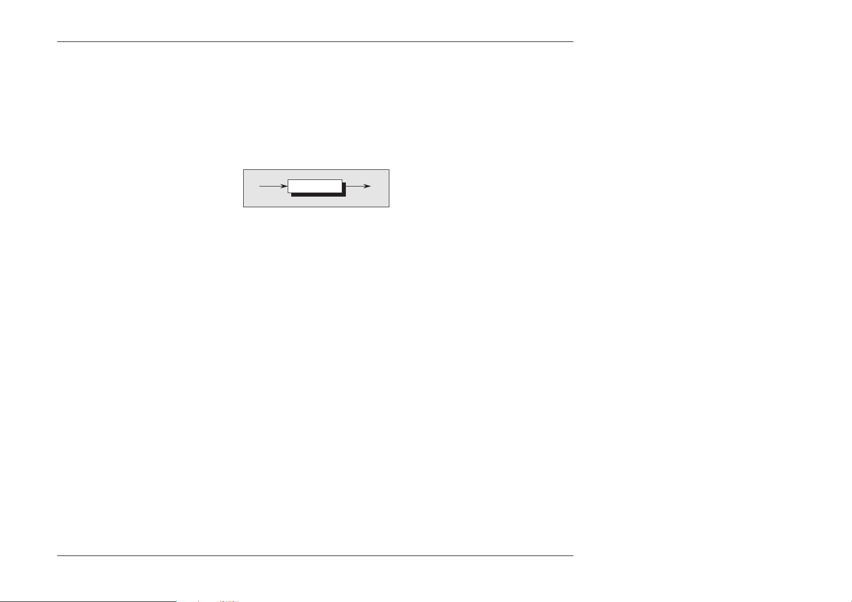
Appendix C to
Section 6 of the
User’s Handbook for
Wavetek Model 9100
IEEE 488.2 Common Commands and Queries Implemented in the Model 9100
6.C.1 Clear Status
This measurement event status data structure conforms to the IEEE 488.2 standard requirements for this structure.
∗
CLS
∗CLS
clears all the event registers and queues except the output queue.
The output queue and MAV bit will be cleared if ∗CLS
immediately follows a 'Program Message Terminator'; refer to
the IEEE 488.2 standard document.
Execution Errors:
None.
Power On and Reset Conditions
Not applicable.
Final Width = 215mm
Appendix C to Section 6: 9100 System Operation — IEEE 488.2 Common Commands and Queries 6-C1
Page 78
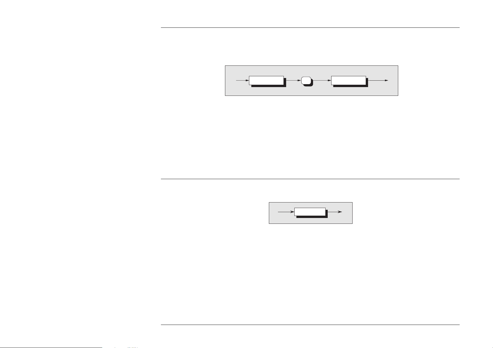
6.C.2 Event Status Enable
This event status data structure conforms to the IEEE 488.2 standard requirements for this structure.
∗
ESE
phs
Nrf
Final Width = 215mm
∗ESE enables the standard defined event bits which will gener-
ate a summary message in the status byte. Refer to Section 6;
Execution Errors:
None.
Subsection 6.5.
Power On and Reset Conditions
Nrf is a Decimal Numeric Data Element representing an integer
Not applicable.
decimal value equivalent to the Hex value required to
enable the appropriate bits in this 8-bit register. The
detailed definition is contained in the IEEE 488.2 standard
document. Note that numbers will be rounded to an
integer.
6.C.3 Recall Event Status Enable
This event status data structure conforms to the IEEE 488.2 standard requirements for this structure.
∗ESE?
∗ESE?
recalls the enable mask for the standard defined events. Refer
Execution Errors:
None
to Section 6; Subsection 6.5.
Power On and Reset Conditions
Response Decode:
The value returned, when converted to base 2 (binary), identifies
the enabled bits which will generate a summary message in the
The Power On condition depends on the condition stored by the
common ∗PSC command - if 0 then it is not cleared; if 1 then the
register is cleared. Reset has no effect.
service request byte, for this data structure. The detailed
definition is contained in the IEEE 488.2 document.
6-C2 Appendix C to Section 6: 9100 System Operation — IEEE 488.2 Common Commands and Queries
Page 79
6.C.4 Read Event Status Register
This event status data structure conforms to the IEEE 488.2 standard requirements for this structure.
∗
ESR?
∗ESR?
recalls the standard defined events.
Refer to Section 6; Subsection 6.5.
Response Decode:
The value returned, when converted to base 2 (binary), identifies
the bits as defined in the IEEE 488.2 standard.
Execution Errors:
None
Final Width = 215mm
Appendix C to Section 6: 9100 System Operation — IEEE 488.2 Common Commands and Queries 6-C3
Page 80

Final Width = 215mm
6.C.5 I/D (Instrument Identification)
This command conforms to the IEEE 488.2 standard requirements.
∗
IDN?
∗IDN?
will recall the instrument’s manufacturer, model number, serial number and firmware level.
Response Format:
Character position
123456789101112
Wavetek Ltd,
13 14 15 16 17
9100,
18 19 20 21 22 23 24 25 26 27 28 29 30
XXXXXXXXXXXX,
31 32 33 34
X.XX
Where:
The data contained in the response consists of four commaseparated fields, the last two of which are instrument-dependent. The data element type is defined in the IEEE 488.2 standard
specification.
A single query sent as a terminated program message will elicit
a single response terminated by:
nl = newline with EOI
If multiple queries are sent as a string of program message units
Response Decode:
The data contained in the four fields is organized as follows:
• First field - manufacturer
• Second field - model
• Third field - serial number
• Fourth field - firmware level (will possibly vary from
one instrument to another).
Execution Errors:
None.
(separated by semi-colons with the string followed by a
permitted terminator), then the responses will be returned as a
similar string whose sequence corresponds to the sequence of
Power On and Reset Conditions
Not applicable.
the program queries. The final response in the string will be
followed by the terminator:
nl = newline with EOI
6-C4 Appendix C to Section 6: 9100 System Operation — IEEE 488.2 Common Commands and Queries
Page 81
6.C.6 Operation Complete
This command conforms to the IEEE 488.2 standard requirements.
∗
OPC
∗OPC
is a synchronization command which will generate an operation
complete message in the standard Event Status Register when
all pending operations are complete.
6.C.7 Operation Complete?
This query conforms to the IEEE 488.2 standard requirements.
Response Decode:
The value returned is always 1, which is placed in the output
queue when all pending operations are complete.
Execution Errors:
None.
Power On and Reset Conditions
Not applicable.
∗
OPC?
Final Width = 215mm
Appendix C to Section 6: 9100 System Operation — IEEE 488.2 Common Commands and Queries 6-C5
Page 82

Recall the 9100 Instrument Hardware Fitment
This command conforms to the IEEE 488.2 standard requirements.
∗
OPT?
∗OPT?
will recall the instrument’s hardware fitment.
Final Width = 215mm
Response Format:
Character position
123456789101112
0 , 0 , 0 , x1 , x2 , x3 nl
Where:
The data in the response consists of comma-separated
characters, each being either 1 or 0.
nl = newline with EOI
The data element type is Nr1 as defined in the IEEE 488.2
standard specification.
Response Decode:
The character positions represent the following hardware fitment:
x1 - Option 600: Oscilloscope Calibrator Module
x2 - Option 100: High Stability Crystal Reference
x3 - Option 250: Oscilloscope Calibrator Module
0 - Positions reserved for future use
x1 = 1 indicates that option 600 is fitted,
x1 = 0 indicates that option 600 is not fitted.
x2 = 1 indicates that option 100 is fitted,
x2 = 0 indicates that option 100 is not fitted.
x3 = 1 indicates that option 250 is fitted,
x3 = 0 indicates that option 250 is not fitted.
Execution Errors:
None.
Power On and Reset Conditions
Not applicable.
6-C6 Appendix C to Section 6: 9100 System Operation — IEEE 488.2 Common Commands and Queries
Page 83

6.C.8 Power On Status Clear
This common command conforms to the IEEE 488.2 standard requirements.
∗
PSC
phs
Nrf
∗PSC
sets the flag controlling the clearing of defined registers at
Power On.
Nrf
is a decimal numeric value which, when rounded to an
integer value of zero, sets the power on clear flag false. This
allows the instrument to assert SRQ at power on, providing that
the PON bit in the ESR is enabled at the time of power-down, by
the corresponding bit in its Enable register (ESE).
When the value rounds to an integer value other than zero it sets
the power on clear flag true, which clears the standard event
status enable and service request enable registers so that the
instrument will not assert an SRQ on power up.
Examples:
∗PSC 0 or ∗PSC 0.173 sets the instrument to assert an SRQ at
Power On.
∗PSC 1 or ∗PSC 0.773 sets the instrument to not assert an SRQ
on Power On.
Execution Errors:
None.
Power On and Reset Conditions
Not applicable.
Final Width = 215mm
Appendix C to Section 6: 9100 System Operation — IEEE 488.2 Common Commands and Queries 6-C7
Page 84

6.C.9 Recall Power On Status Clear Flag
This common query conforms to the IEEE 488.2 standard requirements. The existing flag condition will have been determined
by the ∗PSC command.
∗
PSC?
Final Width = 215mm
∗PSC?
will recall the Power On Status condition.
Response Format:
A single ASCII character is returned.
A single query sent as a terminated program message will elicit
a single response terminated by:
nl = newline with EOI
If multiple queries are sent as a string of program message units
(separated by semi-colons with the string followed by a
permitted terminator), then the responses will be sent as a
similar string whose sequence corresponds to the sequence of
the program queries. The final response in the string will be
followed by the terminator:
nl = newline with EOI
Response Decode:
The value returned identifies the state of the saved flag:
Zero indicates false. The instrument is not programmed to
clear the Standard Event Status Enable Register and
Service Request Enable Register at Power On, so the
instrument will generate a 'Power On' SRQ, providing
that the PON bit in the ESR is enabled at the time of
power-down, by the corresponding bit in its Enable
register (ESE).
One indicates true. The instrument is programmed to clear
the Standard Event Status Enable Register and Service
Request Enable Register at Power On, so the instrument
cannot generate any SRQ at Power On.
Execution Errors:
None
Power On and Reset Conditions
No Change. This data is saved in non-volatile memory at Power
Off, for use at Power On.
6-C8 Appendix C to Section 6: 9100 System Operation — IEEE 488.2 Common Commands and Queries
Page 85

6.C.10 Protected User Data — Entry of User Data
This command conforms to the IEEE 488.2 standard requirements.
PUD
phs
#
1
digit
user message
*
2
digit digit
# 0
where:
phs
= Program Header Separator,
digit
= one of the ASCII-coded numerals,
user message
= any message up to 63 bytes maximum.
Note
The slash-delimited /^END/ box is not outlined. This is to draw attention to the fact that it is not a data element, but represents the
EOI line being set true with the last byte 'NL' to terminate the program message.
Refer to the Standard document IEEE Std 488.2-1992, Sub-section 7.7.6, page 78.
∗PUD
allows a user to enter up to 63 bytes of data into a protected area
to identify or characterize the instrument. The two
representations above are allowed depending on the message
length and the number of ‘digits’ required to identify this. The
instrument must be in calibration mode for this command to
execute.
The data can be recalled using the ∗PUD? query.
user message
/^END/NL
Execution Errors
∗PUD is executable only when the rear panel calibration switch
is in the enabled position and calibration has been enabled.
Otherwise an Execution Error is returned.
Command Errors
A Command Error is returned if the user message exceeds 63
bytes, or if the data does not conform to the standard format.
Final Width = 215mm
Power On and Reset Conditions
Data area remains unchanged.
Appendix C to Section 6: 9100 System Operation — IEEE 488.2 Common Commands and Queries 6-C9
Page 86
6.C.11 Protected User Data — Recall of User Data
PUD?
*
This common command conforms to the IEEE 488.2 standard requirements.
∗PUD? recalls previously entered user data. Refer to program command ∗PUD.
Response Syntax:
Final Width = 215mm
# 2
digit
where:
digit
= one of the ASCII-coded numerals previously determined from the length of the user message string,
user message
= the saved user message.
Response Decode:
The previously-saved message is recalled.
If no message is available, the value of the two digits is 00. The
data area contains up to 63 bytes of data.
A single query sent as a terminated program message will elicit
a single response terminated by:
nl = newline with EOI
If multiple queries are sent as a string of program message units
(separated by semi-colons with the string followed by a
permitted terminator), then the responses will be sent as a
similar string whose sequence corresponds to the sequence of
the program queries. The final response in the string will be
followed by the terminator:
nl = newline with EOI
digit
user message
Execution Errors:
None.
Power On and Reset Conditions
Data area remains unchanged.
6-C10 Appendix C to Section 6: 9100 System Operation — IEEE 488.2 Common Commands and Queries
Page 87

6.C.12 Reset
*
RST
∗RST
will reset the instrument to a defined condition, stated for each
applicable command with the command's description, and listed
in Appendix D to Section 6.
The reset condition is not dependent on past-use history of the
instrument except as noted below:
∗RST does not affect the following:
• the selected address of the instrument;
• calibration data that affect specifications;
• SRQ mask conditions;
• the state of the IEEE 488.1 interface.
6.C.13 Service Request Enable
This Status Byte data structure conforms to the IEEE 488.2 standard requirements for this structure.
SRE
*
∗SRE enables the standard and user-defined summary bits in the service request byte, which will generate a service request. Refer
to Section 6, Subsection 6.5.
Execution Errors:
None.
Power On and Reset Conditions
Not applicable.
phs
Nrf
Final Width = 215mm
Nrf is a Decimal Numeric Data Element representing an
integer decimal value equivalent to the Hex value required
to enable the appropriate bits in this 8-bit register. The
detail definition is contained in the IEEE 488.2 document.
Note that numbers will be rounded to an integer.
Appendix C to Section 6: 9100 System Operation — IEEE 488.2 Common Commands and Queries 6-C11
Execution Errors:
None.
Power On and Reset Conditions
Not applicable.
Page 88

6.C.14 Recall Service Request Enable
This Status Byte data structure conforms to the IEEE 488.2 standard requirements for this structure.
SRE?
*
Final Width = 215mm
∗SRE?
recalls the enable mask for the standard defined events. Refer
to Section 6, Subsection 6.5.
Response Decode:
The value returned, when converted to base 2 (binary), identifies
the enabled bits which will generate a service request. The detail
is contained in the IEEE 488.2 standard document.
6.C.15 Read Service Request Register
This Status Byte data structure conforms to the IEEE 488.2 standard requirements for this structure.
Execution Errors:
None.
Power On and Reset Conditions
The Power On condition depends on the condition stored by the
common ∗PSC command - if 0 then it is not cleared; if 1 then the
register is cleared. Reset has no effect.
STB?
*
∗STB?
recalls the service request register for summary bits. Refer to
Section 6, Subsection 6.5.
Response Decode:
The value returned, when converted to base 2 (binary), identifies
the summary bits for the current status of the data structures
involved. For the detail definition see the IEEE 488.2 standard
document. There is no method of clearing this byte directly. Its
condition relies on the clearing of the overlying status data
structure.
Execution Errors:
None.
Power On and Reset Conditions
Not applicable.
6-C12 Appendix C to Section 6: 9100 System Operation — IEEE 488.2 Common Commands and Queries
Page 89

6.C.16 Test Operations — Full Selftest
This query conforms to the IEEE 488.2 standard requirements.
*
TST?
∗TST?
executes a Full selftest. A response is generated after the test is
completed.
N.B. Operational selftest is valid only at temperatures:
23°C±10°C.
Response Decode:
The value returned identifies pass or failure of the operational
selftest:
ZERO indicates operational selftest complete with no errors
detected.
ONE indicates operational selftest has failed.
The errors can be found only by re-running the self test
manually. Refer to Section 8.
Execution Errors:
Operational selftest is not permitted when calibration is
successfully enabled.
Power On and Reset Conditions
Not applicable.
Final Width = 215mm
Appendix C to Section 6: 9100 System Operation — IEEE 488.2 Common Commands and Queries 6-C13
Page 90
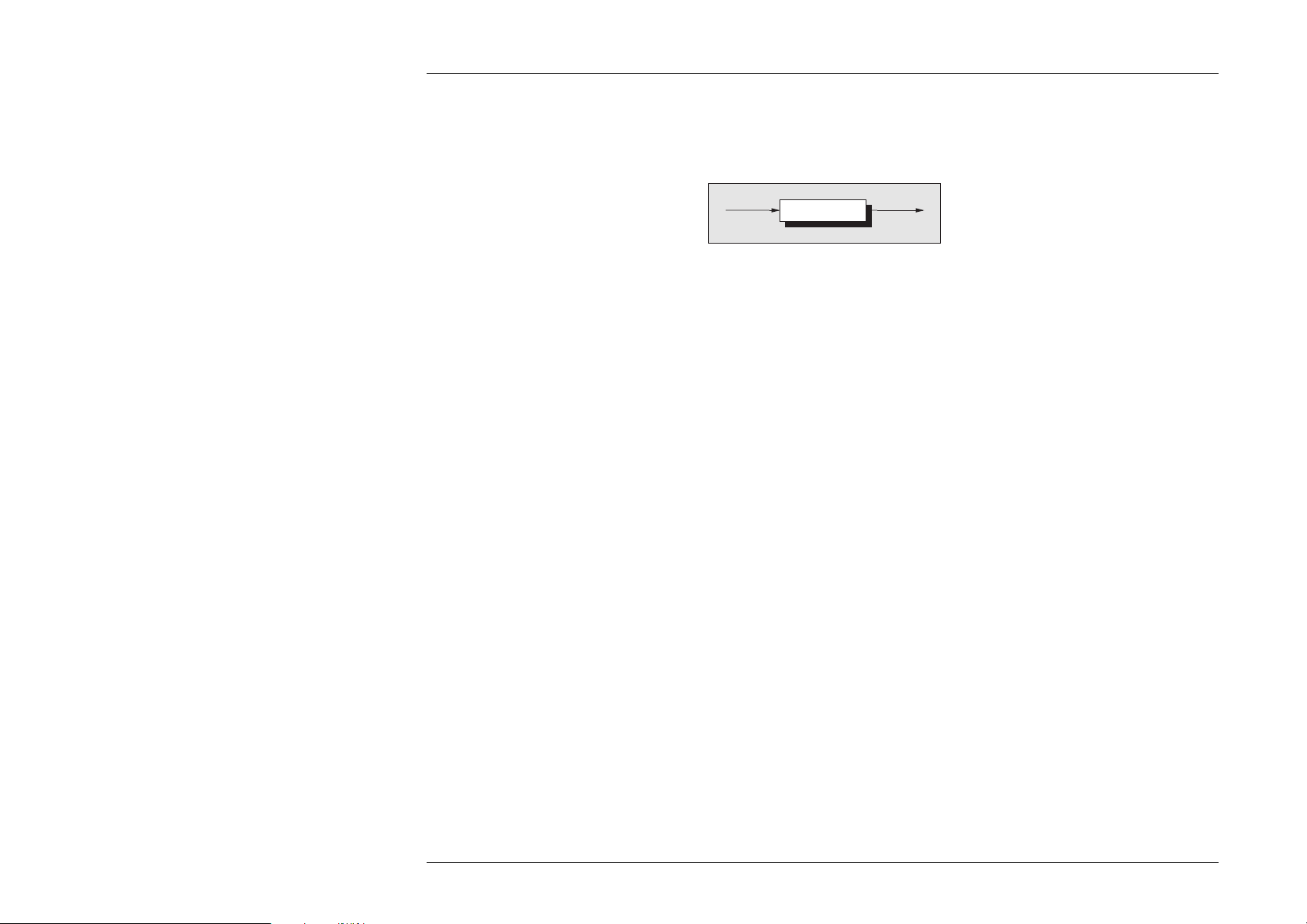
6.C.17 Wait
This command conforms to the IEEE 488.2 standard requirements.
WAI
*
Final Width = 215mm
∗WAI
prevents the instrument from executing any further commands
or queries until the No Pending Operations Flag is set true. This
is a mandatory command for IEEE-488.2 but has little relevance
to this instrument as there are no parallel processes requiring
Pending Operation Flags.
Execution Errors:
None.
Power On and Reset Conditions
Not applicable.
6-C14 Appendix C to Section 6: 9100 System Operation — IEEE 488.2 Common Commands and Queries
Page 91

Model 9100 — Device Settings after ∗RST
6.D.1 Introduction
∗RST
will reset the instrument to a defined condition, stated for each applicable command.
The reset condition is not dependent on past-use history of the instrument except as noted below:
Appendix D to
Section 6 of the
User’s Handbook for
Wavetek Model 9100
∗RST does not affect the following:
• the selected address of the instrument;
• calibration data that affect specifications;
• SRQ mask conditions;
• the contents of:
the Status Byte Register;
the Status Byte Enable Register;
the Standard Event Status Register;
the Standard Event Status Enable Register;
the SCPI Operation Status Register;
the SCPI Operation Status Enable Register;
the SCPI Questionable Status Register;
the SCPI Questionable Status Enable Register;
• the state of the IEEE 488.1 interface;
• the Error Queue;
• the Power-on Status Clear flag setting;
• the Protected User Data Query response.
The 'Enable Macro Command' (∗EMC) is not used in the 9100.
The 'Define Device Trigger Command' (∗DDT) is not used in
the 9100.
Parallel Poll is not implemented in the 9100.
∗RST enforces the following states:
• The 9100 reverts to Manual mode;
• the 9100 is returned to 'Operation Complete Command
Idle State' (OCIS);
• the 9100 is returned to 'Operation Complete Query Idle
State' (OQIS);
• Settings Related to Common IEEE 488.2 Commands are
as detailed in paras 6.D.2, overleaf;
• Settings related to SCPI Commands are as detailed in paras
6.D.3, overleaf;
Final Width = 215mm
Appendix D to Section 6: 9100 System Operation — Device Settings after ∗RST 6-D1
Page 92

Final Width = 215mm
6.D.2 ∗RST Settings Related to Common IEEE 488.2 Commands
Program Coding Condition
*CLS Not applicable
*ESE Nrf Not applicable
*ESE? Previous state preserved
*ESR? Previous state preserved
*IDN? No Change
*OPC OPIC state forced
*OPC? OPIQ state forced
*OPT? Not applicable
*PSC 0/1 Not applicable
*PSC? No change.
*PUD Data area remains unchanged
*PUD? Data area remains unchanged
*SRE Nrf Not applicable
*SRE? Previous state preserved
*STB? Previous state preserved
*TST? Not applicable
*WAI Not applicable
6-D2 Appendix D to Section 6: 9100 System Operation — Device Settings after ∗RST
Page 93

6.D.3 ∗RST Settings Related to SCPI Commands
Keyword Condition
CALibration ......................
Disabled
:SECure
:PASSword required to enter Calibration mode
OUTPut
[:STATe] ...................... OFF
:COMPensation(?) ............... OFF
:ISELection(?) ................. HIGHi
[SOURce]
:FUNCtion
[:SHAPe](?) ................. DC
:VOLTage ...................... Active
[:LEVEl]
[:IMMediate]
[:AMPLitude](?) ....... 1V
:HIGH(?) .............. Not applicable
:LOW(?) ............... Not applicable
:CURRent ...................... Inactive
:RESistance .................... Inactive
:UUT_I(?) ................... LOW
:CONDuctance ................... Inactive
:UUT_I(?) ................... LOW
:CAPacitance ................... Inactive
:UUT_I(?) ................... LOW
:FREQuency ..................... Inactive
:PHASe ...................... Inactive
[:ADJust](?) ................ 0°
:INPut
[:STATe](?) .............. OFF
:OUTPut
[:STATe](?) .............. OFF
:PULSe ...................... Inactive
:TEMPerature ................... Inactive
:UNITs(?) ................... C
:SCALe(?) ................... TS68
:THERmocouple ............... Inactive
:TYPE(?) ................. K
:PRT ...................... Inactive
:TYPE(?) ................. PT385
:NRESistance(?) .......... 100Ω
:UUT_I(?) ................ LOW
Keyword Condition
STATus
:OPERation
[:EVENt]? .... No change
:ENABle(?) ... No change
:CONDition? .. Not applicable
:QUEStionable
[:EVENt]? .... No change
:ENABle(?) ... No change
:CONDition? .. Not applicable
:PRESet ......... Not applicable
SYSTem
:ERRor? ......... Not applicable
:DATE(?) ........ As previously set, updated
:TIME(?) ........ As previously set, updated
:SVOLtage(?) .... As previously set
:VERSion? ....... 1993
Final Width = 215mm
Appendix D to Section 6: 9100 System Operation — Device Settings after ∗RST 6-D3
Page 94

Page 95

Model 9100 — Device Settings at Power On
Appendix E to
Section 6 of the
User’s Handbook for
Wavetek Model 9100
6.E.1 General
Active Mode: The 9100 can power-up in either 'Manual'
or 'Procedure' mode, but Manual Mode or
Calibration mode must be selected for
Remote Operation.
The required mode is selected by pressing
Mode key on front panel and choosing
from the Mode Menu (Calibration mode
requires a password).
Device I/D (Serial Number) Factory serial number preserved
Protected User Data Previous entry preserved
Status Reporting Conditions:
Status Byte Register Depends on state of ∗PSC
Status Byte Enable Register Depends on state of ∗PSC
Event Status Register Depends on state of ∗PSC
Event Status Enable Register Depends on state of ∗PSC
Operation Status Event Register Depends on state of ∗PSC
Operation Status Enable Register Depends on state of ∗PSC
Questionable Status Event Register Depends on state of ∗PSC
Questionable Status Enable Register Depends on state of ∗PSC
Error Queue Empty until first error is
detected
6.E.2 Power-On Settings Related to
Common IEEE 488.2 Commands
Program Coding Condition
*CLS Not applicable
*ESE Nrf Not applicable
*ESE? Response depends on state of *PSC
*ESR? Response depends on state of *PSC
*IDN? Not applicable
*OPC Not applicable
*OPC? Not applicable
*OPT? Not applicable
*PSC 0/1 Not applicable
*PSC? No change. This data is saved at power off
for use at power on.
*PUD Data area remains unchanged
*PUD? Data area remains unchanged
*RST Not applicable
*SRE Nrf Not applicable
*SRE? Response depends on state of *PSC
*STB? Response depends on state of *PSC
*TST? Not applicable
*WAI Not applicable
Final Width = 215mm
Appendix E to Section 6: 9100 System Operation — Device Settings at Power On 6-E1
Page 96

6.E.3 Settings related to SCPI Commands
Final Width = 215mm
Keyword Condition
CALibration ...................... Disabled
:SECure
:PASSword Required to enter Cal Mode
OUTPut
[:STATe] ...................... OFF
:COMPensation(?) ............... OFF
:ISELection(?) ................. HIGHi
[SOURce]
:FUNCtion
[:SHAPe](?) ................. DC
:VOLTage ...................... Active
[:LEVEl]
[:IMMediate]
[:AMPLitude](?) ....... 1V
:HIGH(?) .............. Not Applicable
:LOW(?) ............... Not Applicable
:CURRent ...................... Inactive
:RESistance .................... Inactive
:UUT_I(?) ................... LOW
:CONDuctance ................... Inactive
:UUT_I(?) ................... LOW
:CAPacitance ................... Inactive
:UUT_I(?) ................... LOW
:FREQuency ..................... Inactive
:PHASe ...................... Inactive
[:ADJust](?) ................ 0°
:INPut
[:STATe](?) .............. OFF
:OUTPut
[:STATe](?) .............. OFF
:PULSe ...................... Inactive
:TEMPerature ................... Inactive
:UNITs(?) ................... C
:SCALe(?) ................... TS68
:THERmocouple ............... Inactive
:TYPE(?) ................. K
:PRT ...................... Inactive
:TYPE(?) ................. PT385
:NRESistance(?) .......... 100Ω
:UUT_I(?) ................ LOW
Keyword Condition
STATus
:OPERation
[:EVENt]? ....... Depends on state of *PSC
:ENABle(?) ...... Depends on state of *PSC
:CONDition? ..... Not Applicable
:QUEStionable
[:EVENt]? ....... Depends on state of *PSC
:ENABle(?) ...... Depends on state of *PSC
:CONDition? ..... Not Applicable
:PRESet ............ Not Applicable
SYSTem
:ERRor? ............ Not applicable
:DATE(?) ........... As previously set, updated
:TIME(?) ........... As previously set, updated
:SVOLtage(?) ....... As previously set
:VERSion? .......... 1993
6-E2 Appendix E to Section 6: 9100 System Operation — Device Settings at Power On
Page 97

SECTION 7 9100 SPECIFICATIONS
7.1 General
7.1.1 Line Power Supply
Voltage (single φ): 100V/120V/220V/240V
selectable from rear panel
Variation: ≤ ±10% Nominal Voltage
Line Frequency: 48Hz to 63Hz
Consumption: 450VA max
Power Fuses: 220/240V: T3.15A HBC, 250V, IEC127
100/120V: T5.0A HBC, 250V, IEC127
7.1.2 Mechanical
Dimensions: Height: 3U
Width: 427mm (16.8 inches)
Depth: 460mm (18.1 inches)
Weight: 18.5kg (41lbs)
7.1.3 SAFETY:
Designed to UL1244, IEC348, IEC1010-1:
Pollution degree 2; installation category II;
Protection class I.
7.1.4 Peak Terminal Voltages and Currents
Peak Volts Peak
to Ground Current
SHi 1500V ———
Hi 1500V 90mA
SLo 15V ———
Lo 15V 90mA
I+ 10V 30A
I- ——— 30A
Aux Analog Output 15V 1.5A
7.1.5 Environmental Conditions
Temperature: Operating: 5°C to 40°C
Warm-up Time: 20 minutes
Max. Relative Humidity (non-condensing):
Altitude
Shock: MIL-T-28800, type III, class 5, style E.
Vibration: MIL-T-28800, type III, class 5, style E.
Enclosure: MIL-T-28800, type III, class 5, style E.
EMC:
Transit: -20°C to 60°C <100hrs
Storage: 0°C to 50°C
Operating: +5°C to +30°C: <90%,
+30°C to +40°C: <75%,
Storage: 0°C to +50°C: <95%,
Operating: 0 to 2000m (6,562 ft)
Non-operating: 0 to 12,000m (40,000 ft)
Designed to:
Generic Emissions: EN50081.
Generic Immunity: EN50082.
FCC Rules part 15 sub-part J class B.
7.1.6 The Meaning of 'Accuracy' when used in the
Function Accuracy Tables
Accuracy includes long-term stability, temperature coefficient,
linearity, load and line regulation and the traceability of factory
and National calibration standards. Nothing further needs to be
added to determine the Test Uncertainty Ratio over the instrument
under test.
N.B. These specifications apply to both the Model 9100
output terminals and at the remote end of the Model 9105
lead kit unless otherwise stated.
Final Width = 215mm
Section 7: Model 9100: Specifications 7-1
Page 98

7.2 Options and Associated Products
7.2.1 Model 9100 Option Summary
Option 10 Blank 256kByte, Flash memory.
Option 30 Blank 256kByte, Static RAM (SRAM), battery backed.
Option 50 Tracker Ball.
Option 60 Soft Carry Case.
Option 70 NAMAS Calibration Certificate traceable to National Standards.
Option 90 Rack Mounting Kit.
Option 100 High Stability Crystal Reference.
Option 200 10- and 50-Turn Current Coils.
Option 250 250MHz Oscilloscope Calibrator Module.
or
Option 600 600MHz Oscilloscope Calibrator Module.
Line Voltage: The 9100 is configured for use at the correct voltage at the shipment point.
Final Width = 215mm
7.2.2 Products Associated with the Model 9100
PLC-XXX Procedure Library Cards
Model 9105 Comprehensive Lead Set (one unit supplied with each Model 9100 unit).
Model 9010 Memory Card Procedure Generator, inventory management software and memory card drive, supplied in 3.5"
integral PC mount format, with accessories for external mounting.
(Minimum hardware requirements: 100% IBM compatible, 80486 25MHz DX™ or better, with MS-DOS 5.0™
or later plus Windows™ Version 3.1 or later. 4MBytes of memory, 30MBytes of hard disk space is required for
installation; further hard disk space will be required for generation of procedures, etc. One full-size expansion
slot will be required.)
7-2 Section 7: Model 9100: Specifications
(User's Handbook Section 1, Sub-section 1.4)
.
Page 99

7.3 DC Voltage Specifications
7.3.1 DC Voltage Accuracy and Resolution
Voltage Output Accuracy * Compliance Absolute
+ve & -ve Polarities ±(% of Output + Floor) Current Resolution
1Year — Tcal ±5°C
000.000 mV to 320.000 mV 0.006% + 4.16µV < 20mA 1µV
0.32001 V to 3.20000 V 0.006% + 41.6µV < 20mA 10µV
03.2001 V to 32.0000 V 0.0065% + 416µV < 20mA 100µV
032.001 V to 320.000 V 0.0065% + 4.48mV < 6mA 1mV
0320.01 V to 1050.00 V 0.006% + 19.95mV < 6mA 10mV
∗ = For loads < 1MΩ: add load regulation error.
7.3.2 Other DCV Specifications
Settling Time: to within 10% of accuracy: 0.08s
Load Regulation: For loads <1MΩ: add (200/R
Maximum Capacitance: 1000pF.
[1]
LOAD
) % of output
Final Width = 215mm
NOTES: [1] Tcal = temperature at calibration. Factory calibration temperature = 23°C
Section 7: Model 9100: Specifications 7-3
Page 100

Final Width = 215mm
7.4 AC Voltage Specifications
7.4.1 AC Voltage Accuracy (Sinusoidal Waveshape) and Resolution
Voltage Frequency Accuracy * Current Total Absolute
Output Band
000.000 mV to 010.000 mV 10 - 3k 0.04 + 384µV 20mA 0.06 1µV
010.001 mV to 032.000 mV 10 - 3k 0.04 + 96.0µV 20mA 0.06 1µV
032.001 mV to 320.000 mV 10 - 3k 0.04 + 19.2µV 20mA 0.06 1µV
0.32001 V to 3.20000 V 10 - 3k 0.04 + 192µV 20mA 0.06 10µV
03.2001 V to 32.0000 V 10 - 3k 0.04 + 1.92mV 20mA 0.10 100µV
032.001 V to 105.000 V 10 - 3k 0.04 + 6.30mV 20mA 0.10 1mV
105.001 V to 320.000 V 40 - 100 0.05 + 19.2mV 6mA
0320.01 V to 0800.00 V 40 - 100 0.05 + 63.0mV 6mA 0.50 10mV
0800.01 V to 1050.00 V 40 - 100 0.05 + 126mV 6mA 0.50 10mV
∗ = For loads < |1MΩ|: add load regulation error.
† = Availability of voltage and frequency combinations is subject to the Volt-Hertz limit (see V-Hz profile).
#
= 20mA if the Power Option (Option PWR) is fitted.
7-4 Section 7: Model 9100: Specifications
[2]
(Hz) Distortion
3k - 10k 0.04 + 512µV 20mA 0.10 1µV
10k - 30k 0.06 + 960µV 20mA 0.13 1µV
30k - 50k 0.09 + 1.92mV 10mA 0.20 1µV
50k - 100k 0.20 + 5.12mV 10mA 0.32 1µV
3k - 10k 0.04 + 128µV 20mA 0.10 1µV
10k - 30k 0.06 + 240µV 20mA 0.13 1µV
30k - 50k 0.09 + 480µV 10mA 0.20 1µV
50k - 100k 0.20 + 1.28mV 10mA 0.32 1µV
3k - 10k 0.04 + 25.6µV 20mA 0.10 1µV
10k - 30k 0.06 + 48.0µV 20mA 0.13 1µV
30k - 50k 0.09 + 96.0µV 10mA 0.20 1µV
50k - 100k 0.20 + 256µV 10mA 0.32 1µV
3k - 10k 0.04 + 256µV 20mA 0.10 10µV
10k - 30k 0.06 + 480µV 20mA 0.13 10µV
30k - 50k 0.09 + 960µV 10mA 0.20 10µV
50k - 100k 0.20 + 2.56mV 10mA 0.32 10µV
3k - 10k 0.06 + 2.56mV 20mA 0.10 100µV
10k - 30k 0.08 + 4.80mV 20mA 0.16 100µV
30k - 50k 0.15 + 9.60mV 20mA 0.20 100µV
50k - 100k 0.35 + 32.0mV 20mA 0.32 100µV
3k - 10k 0.06 + 8.40mV 20mA 0.10 1mV
10k - 30k 0.08 + 15.8mV 20mA 0.16 1mV
30k - 50k 0.15 + 31.5mV 20mA 0.20 1mV
50k - 100k 0.35 + 105mV 20mA 0.32 1mV
100 - 1k 0.05 + 19.2mV 6mA
1k - 3k 0.08 + 19.2mV 6mA
3k - 10k 0.08 + 32.0mV 20mA 0.32 1mV
10k - 20k 0.12 + 48.0mV 20mA 0.32 1mV
20k - 30k 0.15 + 64.0mV 20mA 0.32 1mV
100 - 1k 0.05 + 63.0mV 6mA 0.32 10mV
1k - 3k 0.08 + 63.0mV 6mA 0.32 10mV
3k - 10k 0.08 + 105mV 20mA 0.32 10mV
10k - 20k † 0.12 + 158mV 20mA 0.32 10mV
20k - 30k † 0.15 + 210mV 20mA 0.32 10mV
100 - 1k 0.05 + 126mV 6mA 0.32 10mV
1k - 3k 0.08 + 126mV 6mA 0.32 10mV
3k - 10k 0.08 + 210mV 20mA 0.32 10mV
10k - 20k † 0.12 + 315mV 20mA 0.32 10mV
± (% Output + Floor) Compliance Harmonic Resolution
[1]
1 Year — Tcal
± 5°C (% of Output)
#
#
#
0.50 1mV
0.32 1mV
0.32 1mV
 Loading...