

Page 1

Page 2

Table of Contents
Acknowledgment .......................................................... 2
Register Now!
Section 1: How to use PS22 & DLA................................ 3
Section 2: In-depth topics ........................................... 26
Introduction .................................................................................... 3
Chapter 1........................................... Essential overview ................ 6
Chapter 2 ............................................................. PS-Split .............. 13
Chapter 3...................................... Using PS22 with DLA.............. 18
Chapter 4............................................................ Tutorial.............. 20
Chapter 5....................... Setup library and applications.............. 23
A word about Phase.............. 26
Using PS with Waves S1 .............. 26
Using PS with Waves TrueVerb.............. 26
Stereo inputs.............. 27
Spreading non-central mono sounds.............. 28
Subjective comments and hints.............. 29
Processing Aims.............. 29
Sweeps, Spread statistics, and coloration .............. 30
Mono compatibility.............. 30
A workaround when mono compatibility is critical .............. 31
When is a mono input mono?.............. 31
The technical bit.............. 32
Stereo Monitoring.............. 33
PS-Spread as an audio phase scrambler—A specialist use .............. 34
Q10 Pseudostereo effects .............. 35
Factory Presets ............................................................ 36
Setup Library Notes ..................................................... 42
PS22-DLA product team: Michael Gerzon, Meir Shashua, Seva, Yoel
Users Guide written by: Michael Gerzon, Seva, Meir Shashua
PS22 Plug-In Manual
11
1
11
Page 3

Acknowledgment
Michael Gerzon, the inventor of the PS22 process, died in May 1996, only a few months before releasing this product. Michael invested years of mathematical research, as well as audio engineering into this new type of process.
Although the basic process underlying PS22 was previously incorporated into some commercial products, PS22 is
the first time this process has been made available as a precision tool for pro audio engineers.
Michael did live to see the last stages of development of PS22, and was very pleased with what he saw and heard.
This Users Guide was drafted by Michael, and is a vivid example to the devotion this man had into creating excellent
audio processing tools, and educating for their correct use and understanding. This is especially evident reading the
text in Section 2: In-depth topics, which is almost untouched from Michael’s original draft.
Process licensed from Trifield Productions Limited, US Patent 5671287
PS22 Plug-In Manual
22
2
22
Page 4

Introduction
PS22 StereoMaker is a set of tools for creating convincing stereo results from mono source material as well as a set
of true stereo-in/stereo-out processing tools for synthesizing a richer stereo effect from existing stereo material.
It is far more than merely another “pseudostereo” effect. It is a mixdown and remastering tool capable of producing
subtle or dramatic stereo effects of a kind and quality previously impossible - something that will become an
essential tool in everyday stereo production of all kinds.
The idea of synthesizing a fake stereo effect from mono sources is a very old one, but the results have usually been
disappointing and very often virtually unlistenable, giving unpleasant and unconvincing results. StereoMaker’s
tools are unique, and have been designed after decades of research to avoid the problems of previous processes.
Several aspects distinguish StereoMaker tools from previous pseudostereo effects:
(i) tonal neutrality. All StereoMaker processing preserves the original frequency response. Any tonal
alteration should be the result of intentional equalization desired by a user, not an accidental byproduct
of stereo processing. StereoMaker is designed to leave the tonal quality of the original source unaltered.
(ii) Very low phasiness. The unique patented StereoMaker processing produces sounds of low phasiness,
giving a highly listenable sound. Ordinary stereo pans sounds to different positions with low
interchannel phase difference. Previous pseudostereo processing caused large interchannel phase
differences which produced a vague and phasey sound which was not pleasant to listen to for
extended periods.
(iii) Stereo-in/stereo-out processing. While StereoMaker processing can be applied to central mono
sounds to produce a stereo spread effect, StereoMaker is unique in actually working with full stereo
inputs, spreading each input stereo sound source around its position in the original stereo stage. This
means StereoMaker can be used to enhance the spread of each sound image within a stereo mix, or
with panned mono sound. StereoMaker thickens the stereo width of any stereo sound source around
its original position. This gives much more flexibility in composing rich stereo mixes than processes
that only give a blanket spread to central mono sounds.
(iv) Wide spread effect. While StereoMaker is fully adjustable to achieve subtle narrow degrees of spread if
desired, it is unique in the extreme of wideness of effect it can achieve. StereoMaker allows very extreme left-
right stereo to be achieved which nevertheless sounds convincing and real. Conventional pseudostereo is
often sufficiently subtle that stereo effects are quite difficult to hear other than when doing straight
A/Bcomparisons with the original mono.
PS22 Plug-In Manual
33
3
33
Page 5

(v) intuitive user controls and interface. All synthesis of stereo from mono inevitably involves an artistic
judgment as to where sounds should appear from in the stereo stage, since there is no position informa
tion in the original mono. StereoMaker provides a range of user controls that allows the stereo effect to be
composed in an intuitive manner, offering not just control of the degree of spread and spaciousness, but
also positioning of dominant sounds within the stage. A graphical display shows stereo positioning as a
function of frequency.
(vi) No unwanted processing side effects. StereoMaker aims at avoiding any sound alterations other than
those needed to create a convincing stereoism. As such, it has no conflict with other kinds of processing
such as EQ or reverb. In particular, StereoMaker is not a reverb or echo effect, so that the original artistic
decisions in the monosound are not being modified. StereoMaker may be used with EQ tools such as
Waves Q10 or with room simulation tools such as Waves TrueVerb for more creative effects - the user’s
choice of the nature of each effect is preserved.
PS22 StereoMaker is a toolkit of three separate processes, packaged as two plug-ins, which may be used separately or
in various combinations. The three processes are all stereo-in/stereo out, and are each optimized to achieve different
kinds of results. Their stereo sound is very different from each other, and you will soon discover which kind of
process is suited to different artistic or creative needs. None of the processes is a substitute for the others - they are
all different.
The three processes are: PS-Spread, PS-Split, and DLA. All the PS processes share the low phasiness, and stereo
compatibility features as described above. Each of the two master plug-ins have at least two component plug-ins,
which will be described in this chapter. The DLA ‘family’ of plug-ins comes with the PS package, and is designed to
be used in conjunction with the PS processes in specific ways.
PS22 StereoMaker plug-in
This master plug-in has three components: PS22-Spread, PS22-Split, and PS22-XSplit.
PS-Spread creates a smooth spreading of sounds across the stereo stage. It not only has low phasiness and the
capability of spreading around any stereo position, but it also offers adjustment of additional bass spread enhancement for an exceptionally spacious effect.
The (10) version has only 10 sweeps, and therefore uses less DSP. All the PS plug-ins are based on the controls of the
PS-Spread, so you should read
Chapter 2: PS-Spread before reading about any other component’s controls.
PS-Split completely splits sounds across the stereo stage. Visually speaking, the graphic representation of the PSSplit looks like a square wave swinging between left and right, where the PS-Spread effect looks like a sine wave. The
resulting effect is a dramatic left-right split. Best results are normally achieved when PS-Split is followed with one of
the DLA-X process (or a reverb effect), but it can be used without them.
PS-XSplit is almost the same as PS-Split followed by DLA-XL built into a single interface. The DLA-X and PS-Split
processes complement each other to create a more natural, yet
having the two processes combined into one user interface and linking some controls, it is much easier for you to
achieve optimal results.
PS22 Plug-In Manual
44
4
44
There are two variations of this plug-in: PS22-Spread and PS22-Spread(10).
more spectacular stereo effect, as explained below. By
Page 6

DLA plug-in
In the DLA plug-in are 6 components, two of which are not part of the PS process, but are small plug-ins to
compensate for the delay in the C1 and L1 plug-ins. See the DLA chapter for more detail on these components.
The DLA-X process family is based on short time stereo cross feed delays (not an echo effect). DLA-X is the basic
effect; DLA-XL controls the amount of cross feed separately for the high and low frequencies, and DLA-XLB has an
optional longer delay of low frequencies. While DLA-X processors can be useful used on mono input sources, it is
most effective on stereo inputs, and especially when used in cascade with either PS-Spread or PS-Split can give
spectacular and dramatic results.
The DLA-X and PS processes complement each other. When used on mono input sources DLA-X tends to produce
a comb-filter coloration side effect as a result of the interaction between the delayed and original sound. On the
other hand, PS-Split (and for a lesser extent PS-Spread) will split the spectrum of a central sound so that distinct
frequency bands will exist only in one of the two stereo channels, this has a different kind of coloration side effect.
When DLA-X and PS plug-ins are used together, the DLA-X cross-feeds the missing frequency bands from one
channel to the other, but since each channel has different frequency bands, the interaction between the delayed and
original signal is avoided. A similar, but more complex effect takes place on stereo input.
Note that following PS-Split by a stereo compatible reverb will achieve similar results, so using DLA-X is not
needed in this case.
PS-Split is the tool to use when you wish to split input mono sounds into two almost completely separate stereo
positions, e.g. for a dramatic left-right split. It is capable of extreme and dramatic stereo separation effects. Best
results are normally achieved when used in conjunction with one of the DLA-X plug-ins, but it can also be used
either on its own or with a reverb effects unit.
All three effects are fully user-adjustable from zero effect up to a high degree of effect — as much or as little reprocessing of stereo effect as you want or need. The quality as well as amount of the stereo effect is also fully under user
control.
The PS22-Spread component has the basic set of controls common to all 3 PS components. In the PS-Split component chapter, only the additional controls will be discussed. Therefore, we’ll describe each control of the PS22Spread in detail.
55
5
PS22 Plug-In Manual
55
Page 7

Chapter 1 - Essential overview
Controls
These fall into two groups: Input and Spread.
Input Controls
Gain From 0.0 to -24.0dB. Adjusts input level so that potential output clipping problems can be avoided.
Width Adjusts the width of an input signal all the way from mono (width 0.00) to original stereo (width
1.00). Used to adjust the degree of stereo retained from the input signal before the PS22 spreading effect.
This lets you collapse the input signal to avoid making a signal too wide with the PS process.
Rotation In degrees from -45.0 to +45.0. Exactly like the S1’s Rotation control, adjusting the centering of the input
stereo signal without affecting level-balance. Useful for centering off-center input material or for panning mono material to the left or right.
Channel polarity and channel swap buttons. These are intended to correct errors in the input stereo signal. The +/
- buttons adjust the polarities of the individual channels. Normally, both should be set to “ + “, but if the
input stereo is out of phase, the button on one channel should be set to “ + “ and the other to “ - “. You
should not normally set both buttons to “ - “ unless you understand why are you are doing this. The <->
(channel swap) button swaps left and right channels at the input if the stereo channels have accidentally
been reversed or where it is desired to reverse the input stereo effect.
PS22 Plug-In Manual
66
6
66
Page 8
Spread controls
These controls affect the way sound images are spread and will be described in terms of what they do to a central
mono input sound. The effect for other stereo input sounds will be described in more detail later in the manual.
They are divided into two groups. The top line of controls under the graphical display are
and the bottom line of controls are
Spread statistics controls.
Spread envelope controls,
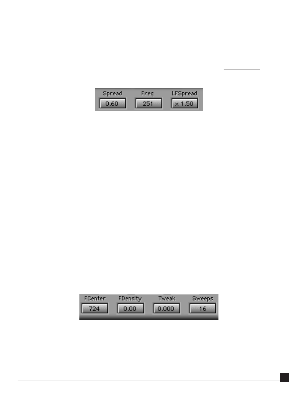
Spread envelope controls
These control the total degree of spreading as a function of frequency.
Spread Adjusts the degree of spreading from 0 (no spreading) to 1.2 (ultra wide spread). A spread of 1
fills the sound stage between the two stereo loudspeakers. By using Spread together with the
input Width control, and the MS metering (see details below) you can adjust the overall stereo
content of your output signal so it is not exaggerated.
Freq In Hertz (Hz). This adjusts the frequency at which bass spread starts acting. A good starting
value is 630 Hz, although the range covers from 32 Hz to 16kHz.
LFspread This provides additional adjustment of spread at bass frequencies. The degree of spread is the
same as at high frequencies if LFspread is 1.0, the bass is wider and more spacious if larger values
of LFspread such as 2.0 are used, and the bass becomes more mono and centered in the stereo
stage if a smaller degree of LFspread approaching 0.0 is used.
Spread statistics controls
These four controls adjust the precise way the input sound is panned to and fro between left and right as a function
of frequency. The panning is shown on the display graphic.
Sweeps This control is the number of sweeps between left and right across the entire audio frequency range.
In other words, how many bands the audio is divided into. The value ranges from 2 to 22 [or 2 to
10 in the PS-Spread(10)], . For 2 it sweeps from left to right and then back to left again as one goes
from low to high frequencies, up to 22 sweeps. (Note that at some control settings, some of the
sweeps to-and fro may be outside the graphic display frequency range).
PS22 Plug-In Manual
77
7
77
Page 9
FCenter In Hz. This control adjusts the center frequency around which the density of sweeps to-and fro
can be increased or decreased by the FDensity control. This allows the maximum degree of toand-fro processing to be concentrated mostly in a given frequency range if desired.
FDensity This controls weather to increase or decrease the density of sweeps around the FCenter frequency. When
set to 0, the to-and-fro sweeps are fairly uniformly distributed across the audio frequency range. For
positive values of FDensity, the to-and-fro sweeps are more dense near the FCenter frequency and less
dense far away from it. For negative values of FDensity, the to-and-fro sweeps are spaced wider apart near
FCenter frequency, and more dense at the bass and treble ends of the audio range.
Twea k For a given setting of the other controls, this control allows the user to tweak how particular
frequencies are panned within the spread stereo stage. When varied between -1 and +1, each
individual frequency will be panned trough all the possible positions between left and right. It is
usually the most useful control when trying to achieve a balanced spread sound stage between
left and right loudspeakers.
Important note for when Sweeps = 2. FCenter and FDensity controls do not work for 2 Sweeps, and Tweak then
only has the effect of reversing the left and right aspects of spreading when set outside the range -0.5 to + 0.5. The
main controls for altering spreading effect with 2 Sweeps are provided by the three spread envelope controls Freq,
Spread and LFspread. The effect of FCenter, FDensity and Tweak becomes more evident when Sweeps is 3 or higher.
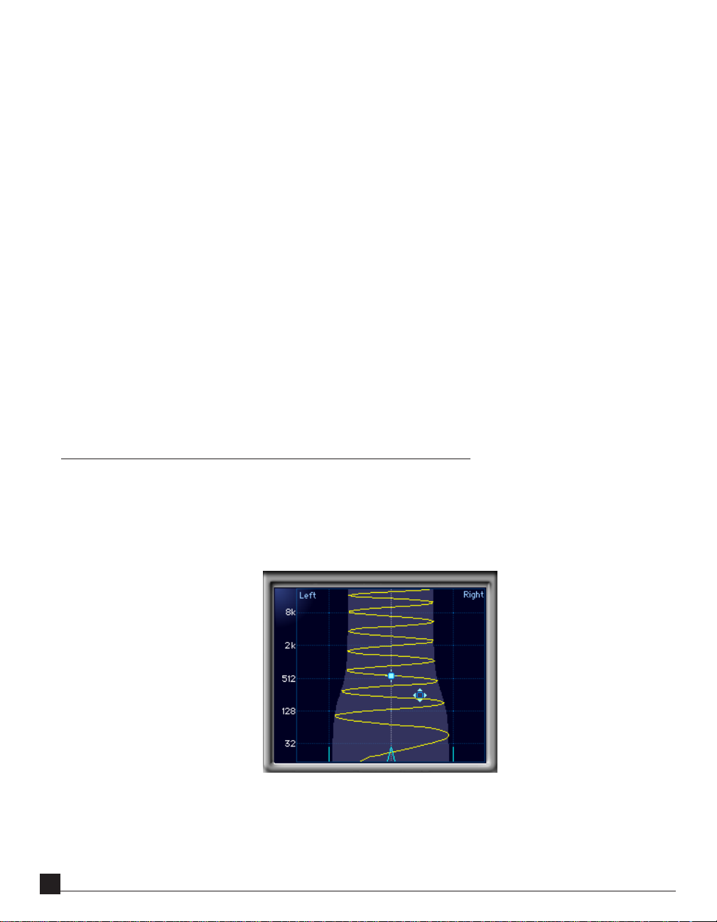
Graphic display
The graphic display of PS-Spread displays the way stereo position of a central mono input source is varied at the output as
a function of frequency. Also shown in light blue is the overall spread envelope, i.e. the degree of spreading as a function of
frequency. The vertical grid lines show left, center and right stereo positions. If the stereo position is shown beyond the left
or right lines, this corresponds to signals having an antiphase relationship between the two stereo channels.
The graph also has two cursors. The solid-square Density cursor (shown upper left in graphic) controls FCenter
frequency vertically and FDensity horizontally. Pressing the option key while dragging vertically changes the Tweak
instead of the FCenter value. -
PS22 Plug-In Manual
88
8
88
Page 10
The open-square Spread cursor (shown lower right in graphic, with four arrows) controls the Spread horizontally
and the transition Frequency of the spread envelope vertically, Pressing the option key while dragging horizontally
changes the LFspread instead of the Spread value.
Either of these grab markers may be selected and dragged by clicking on them with a mouse and dragging them to
new values.
When you drag the Spread cursor, the graph is redrawn in real time to indicate the relative spread of high and low
frequencies, and the transition frequency.
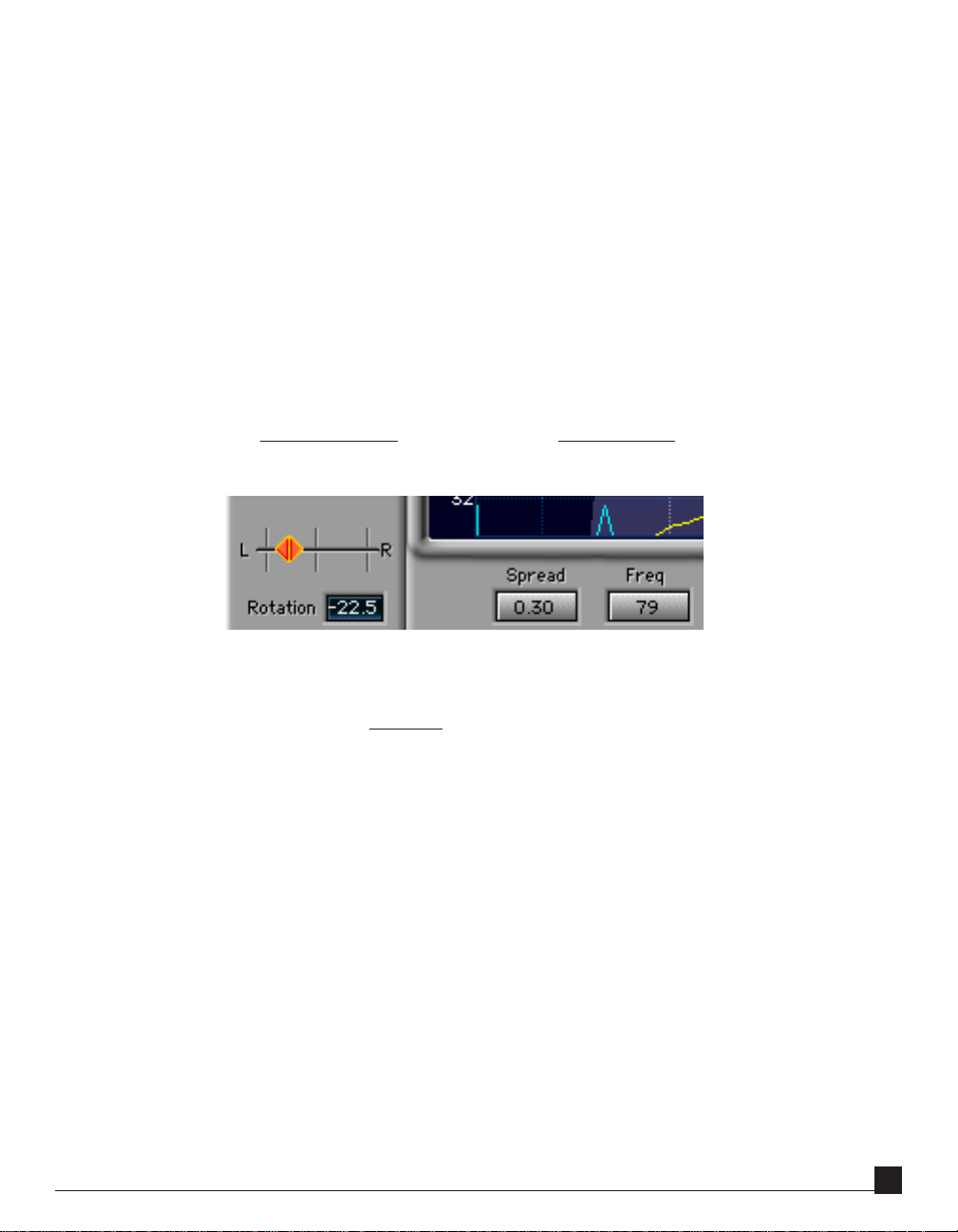
The graphic display also shows the Rotation and Width of the input control settings as light blue lines for the left
and right, and a light blue pointer (an upside-down “V”) in the middle, showing the center of the signal (see
graphic below). These three markers are the Input Stereo cursors.
You can drag these Rotation and Width lines directly in the graph, or on the faders on the left of the graph. In both
the graph and the faders,
horizontal mousing controls the Rotation, vertical mousing controls Width.
It is important to have these lines displayed so that you can see when you might be getting “too wide” with the
output. The light gray vertical lines that go from top to bottom on the graph show the normal Left and Right pan
positions. Anything outside these lines is
anti-phase, which, although it might sound great, may have mono-compatibility problems, or might be fatiguing for long listening periods. Therefore, by putting the Rotation and Width
display on the same graph, you can see if excessive width might be caused by the PS process.
If you have a very wide stereo input, it is advisable to reduce the Width somewhat before applying the Spread. By
using the graph and the MS meters, you have a lot of information that can help create a highly-listenable and
creative sound. The MS meters are discussed in the next section.
PS22 Plug-In Manual
99
9
99
Page 11
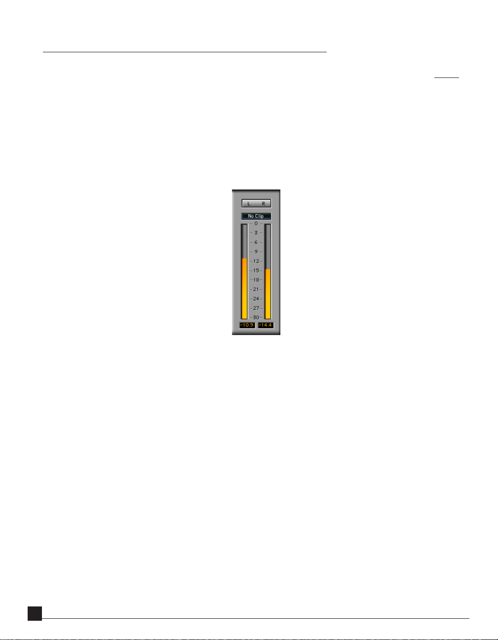
Metering
On the right side of the PS22 window are the bar level meters. The meters always indicate the current output of
PS22. Above the meters is a clip light. If a clip occurs, the Clip Box above the dB meters will indicate “clip” until the
meters are reset.
The clip indicator light is always active, including during non real time (NRT) file based Processing. This is a great
advantage in determining whether a clip occurred during the NRT Process of a file.
Below the level meters are digital values showing the highest peak encountered. To reset these peak level values and
the clip indicator, just click anywhere inside the level meters.
Although the PS22 processing is designed not to change the energy levels of incoming sounds, it does alter both the
phase and the stereo positioning of different sound components in the input signal. This can cause the output peak
levels to be higher than in the input stereo signal. In some very extreme cases, peak levels can be increased by 9 dB
or more - although this is very rare, and figures of 2 or 3 dB are more common. If the output meters indicate
clipping as a result, you are advised to reduce input gain to avoid clipping.
PS22 Plug-In Manual
1010
10
1010
Page 12

LR and MS display modes
The PS22 meters have two modes of display: LR, and MS. The LR mode is the standard Left and Right level meters.
Using the MS mode is explained below. The MS mode only affects what the meters display, and has no effect on the
output. The mode may be selected by clicking on the L-and-R/M-and-S button above the meters.
Uses of MS meter mode
MS metering mode displays the levels of two signals, M representing the amount of mono present, and S representing the side signal, i.e. the signal representing the differences between the two stereo channels. The greater the degree
of stereoism present, the higher the S signal when compared to the M signal.
Judging effect of spreading
On mono inputs, MS metering can be useful in indicating the degree of stereoism produced by a given degree of
spread processing. Generally speaking, the widest spatial effect will be obtained when M and S levels are roughly
equal, with a narrower effect if S level is smaller than the M level. If the S level is typically larger than the M level, this
may indicate an excessive degree of spread processing that could sound fatiguing on extended listening or could
lead to mono compatibility problems.
Diagnosing stereo input problems
In general, spread processing will only be successful if applied to input stereo signals that are in phase and not
excessively wide. The MS metering on PS22 can be used to help diagnose problems with the input stereo signal.
Without processing, i.e. with zero spread, and width at 1 and rotation at 0, the MS meter mode can be used to judge
whether the input stereo material is in phase. If it is, the M level will generally be significantly higher than the S.
If, without processing, the S level is generally higher than the M level, this indicates one of two possibilities:
PS22 Plug-In Manual
1111
11
1111
Page 13

(1) the most likely, that the input channels are out of phase, for example due to an analog-domain wiring error in
balanced cables somewhere in the stereo signal chain, an incorrect setting of a phase switch, or possible an
incorrectly wired microphone capsule in a stereo pair of microphones. Correct this by altering one only of the
two input polarity buttons to read “ - “ rather than “ + “. Monitor the output to verify that changing the polarity
does indeed improve the sharpness of stereo images, particularly for sounds at the center of the stereo stage.
(2) in unusual cases (such as certain specialist one-point stereo microphone recording techniques such as MS or
“Blumlein figure-of-eight” when presented with a very wide sound source stage, or if previous excessive width or
spread adjustment has been used) it is possible that the S meter can read higher than the M
without a channel
polarity error due to excessive width. In this case, center stage sounds WILL be in phase, and the phase switches
should NOT be used.
If the input stereo is in-phase but very wide according to the levels indicated on the S meter, then the effect of PS
processing may sound excessive, and you may find it useful to use the width control to narrow the stereo input
image first.
PS22 Plug-In Manual
1212
12
1212
Page 14

Chapter 2 - PS-Split
The PS22 PS-Split and XSplit components are designed primarily to take a mono input and to spread different
frequencies to and fro around the central position. Each frequency is panned to a different position within the
stereo stage, as shown on-screen.
PS-Split differs from PS-Spread mainly in that the PS-Spread has “sine-wave” panning, and the Split has “square
wave” panning, where most frequencies are either panned sharply to the left or right position, with very few frequencies in-between. It is called PS-Split because it in effect splits the frequency components of a mono sound
between just two positions in the stereo stage. PS-Split is preferred in cases where a very dramatic stereo effect is
wanted.
Split and XSplit both have a Shape control that alters the “waveform” of the splitting of the signal. For instance, it
can vary from a smooth panning similar to the Spread, or to a “square wave”, with almost all sounds being panned
completely apart with very fast transitions between these bands.
PS-Split and XSplit have identical controls to PS-Spread, except for these changes:
1 — There is no LFspread control (the low frequency spread is always set to 0).
2 — Freq now adjusts that frequency below which spread is pulled towards 0. The range of the frequency
control is still 32 Hz to 16kHz.
3 — The Sweeps range is from 2 to 10.
4 — The Shape control.
PS22 Plug-In Manual
1313
13
1313
Page 15

Shape control ranges from 0.00 to 1.25.
When Shape=0.00, it is more of a triangle waveform.
Shape=0.15, the shape is the same as the sine-wave shape of the Spread.
Shape=1.00, the shape is square-wave.
Shape=1.25, the shape is a HyperSquare that has some ‘overshoots’.
The Shape control make the PS-Split similar to a variable PS22-Spread(10), so for sound design applications where
you might want a larger degree of stereoism, the Split version gives you more flexibility, although the number of
Sweeps is limited due to DSP requirements.
Adjusting the Shape control is almost completely by subjective choice, and should be used “to taste”.
Split and XSplit are generally used for taking a mono input and creating a strongly separated stereo image from it,
but can be used with stereo inputs as well. The Spread (or Split with lower values of Shape) are generally recommended for stereo inputs, but there are no rules, just suggestions!
PS-XSplit plug-in
The XSplit also has a DLA-XL “built-in”, and doesn’t require the external plug-in, unless you need the XLB, which
you can simply use inserted after the Split component.
The DLA-XL is fully integrated into the logic of XSplit and takes in account the internal settings of the XSplit
parameters when computing it’s own settings. Two additional controls are given to the user: Delay and Xfeed.
Delay is exactly the cross feed delay as in DLA-XL.
Xfeed is different from the DLA-XL control in that it takes in account the current setting of Spread. When Xfeed =
1.0 the amount of cross feed fully compensates for the current degree of Spread, Xfeed<1.0 means the Spread is
partly compensated. Normally the recommended setting is Xfeed=0.5.
The settings of the low frequency transition and Xfeed are set internally according to the Spread transition
frequency.
Here is why the Xfeed and LF settings have an “auto” compensation, and it’s important.
The best Xfeed gain should
be equal to or less than the Spread value (when Shape is 1.0, a “square wave”). Therefore, you can set XFeed to a
value, then when varying Spread, XSplit will automatically “track” the crossfeed gain for you. XFeed also compensates for varying shapes.
For setting the Xfeed gain when using separate plug-ins (like Spread and DLA-X) see the next chapter,
with DLA.
PS22 Plug-In Manual
1414
14
1414
Using PS22
Page 16

The DLA-XLB plug-in windowThe DLA-XLB plug-in window
The DLA-XLB plug-in window
The DLA-XLB plug-in windowThe DLA-XLB plug-in window
This plug-in provides 6 different components:
DLA a simple, single-sample increment delay plug-in, mono/stereo, with display in milliseconds (ms) and
samples; adjustable from 1 to 1024 samples (approximately 0.02 to 23ms @44.1kHz). This is for
simple effects, azimuth adjustment, etc.
C1delay to compensate for the C1 delay, which is 340 samples.
L1delay L1 compensation, 64 samples
and the more sophisticated delays, for use with the PS plug-ins:
DLA-X crossfeed of one channel to the other, with a delay; this is wideband crossfeed; stereo-only.
DLA-XL the DLA-X, plus a Low Frequency crossfeed control and crossover point.
DLA-XLB the DLA-XL, plus an extra Bass delay (an on/off toggle).
Each of the DLA-X plug-ins, has more features, and uses more DSP. If you don’t need a feature you can use the
simpler plug-in and save DSP power.
PS22 Plug-In Manual
1515
15
1515
Page 17

About the DLA-X ‘family’
The DLA-X tools are in general stereo-in/stereo-out processors that (1) increase the stereo effect, (2) maintain the
overall stereo frequency response. They are based on adding short time-delayed stereo signals to the original stereo
that are too short to be heard as discrete echoes. Their main effect is to add an enhanced “bigger” or more spacious
quality to the input mono or stereo signal. DLA-X is designed specifically as an enhancement to the PS-Spread or
PS-Split StereoMaker processes. Inserting the DLA-X process after a PS processor can result in a highly convincing
synthetic stereo effect on mono input sources.
This can be easily heard by listening to just one channel of a PS output, which of course will be missing frequencies
that are on the other channel; this could be fatiguing over a long period of time. By using the DLA-X processes, each
channel is delayed between 5 and 20 milliseconds and added back to the opposite channel. In this way, each channel
still has the original frequency response, does not have the ‘comb-filter’ sound, and in fact the stereo image spread is
increased!
DLA controls
Delay In milliseconds from 0.5 to 20ms (and shown in samples on the DLA plug-in). This controls the
timing of the added delay. Generally values between 5.0 and 20 ms are recommended. Popular
music and speech will benefit from delays between 6 and 12 ms, and classical music from delays
between 12 and 20 ms.
XFeed The ratio of direct to delayed sound. (1.0 is unity gain, 0.5 is -6dB, 0.0 is off). Generally a value
of 0.5 is around optimal, with values between 0.3 and 0.65 generally recommended, but any
values up to 1.0 may be used. Settings near 1.0 can give a spectacular (but maybe colored and
oppressive) effect, and when less than 0.25 can give a subtle and not always obvious effect.
PS22 Plug-In Manual
1616
16
1616
The DLA-XL plug-in windowThe DLA-XL plug-in window
The DLA-XL plug-in window
The DLA-XL plug-in windowThe DLA-XL plug-in window
Page 18

XFeed LF: (DLA-XL, and XLB only) Separate control for the ratio of direct to delayed sound on low frequencies.
Xfeed LF is used as a multiplier of Xfeed, so that If you have Xfeed=1.0 and Low Xfeed at 0.0,
and the Freq at 500, nothing below 500Hz would be cross-fed to the other channel. Everything
above 500
would be delayed and cross-fed. This lets you selectively reduce the amount of low
frequencies that are cross-fed, which can be very helpful, depending on the source material.
More application details are in the chapter
Using PS22 with DLA.
Freq: (DLA-XL, and XLB only) In Hz. The transition frequency below which Xfeed LF is effective.
Bass Delay: (DLA-XLB only) When ‘On’, the frequencies below 160Hz are delayed an additional 9ms to offer a
possibly improved subjective bass response, which is highly dependent on the source material.
Some sources will sound better with the delay, some not.
Trim/Clip On the DLA-X, XL, and XLB, (but not on the simple DLA plug-in), at the right edge of the
screen are two displays in dB. Due to the nature of a crossfeeding delay, peak levels can be
increased by as much as 3dB, and even more if filtering is also involved. If this happens, the Clip
display will turn red and show the value in dB by how much the gain must be reduced to avoid a
clip, as seen in the top graphic.
To adjust gain, just click on the Tr i m display and it will automatically insert the value shown in
the Clip display. You can also drag up and down on the Trim display to manually set the gain,
with a range of 0.0 to -6.0dB.
The clip indicator is always active, including during file-based Processing (whether destructive or
constructive). This is a great advantage in determining whether a clip occurred during a file-based
Process.
PS22 Plug-In Manual
1717
17
1717
Page 19

Chapter 3 - Using PS22 with DLA
The impact of the effect when PS22 is followed by a DLA processor can not be obtained by any single process on its
own. You will get the maximum benefit and most spectacular stereo from the PS22 StereoMaker system by using
more than one process together (or the combined PS22 XSplit). This chapter advises on how this can be done for
most dramatic effect. This does
about 0.35 or less. DLA-X series plug-ins are not needed then.
The various rules given are for guidance about how to avoid unwanted side effects such as coloration or loss of
psychoacoustic effects. However, feel free to break the rules if your ears really like the resulting effect!
Typically the PS plug-in (Split or Spread) should precede the DLA-X plug-in. (Remember, PS-XSplit has a built-in
DLA-X, there is no need for another one.)
not necessarily apply for very subtle uses of the PS plug-ins, say when Spread is
You can put them in any order,
however, if you are going to adjust the Width of a stereo input in the PS component,
it is best to always put the DLA plug-in after it in order to avoid any comb-filter coloration in non-central sounds.
Especially with wider PS-Spread or PS-Split settings, the effect of adding DLA with XFeed set to 0.5 can be spectacular, filling out the stereo stage and making it much more convincing. This works extremely well even for a low
number of Sweeps in Spread or Split, even when Sweep=2, spreading gives very remarkable results.
Although the standard PS-Spread and PS-Split modules use up most of the DSP power of some DSP cards, the
Spread can be used with the basic DLA-X on most DSP cards, at least at the 44.1 kHz sampling rate.
If, and only when, Width=1 on PS-Spread or PS-Split modules, the effect of putting a DLA-X plug-in before or after
the PS will be the same, so that the order of the components is not important.
PS22 Plug-In Manual
1818
18
1818
Page 20

Recommended DLA settings
For these examples, we assume you have inserted a DLA-X, XL, or XLB after a PS-Spread or Split plug-in.
Xfeed 0.3 to 1.0, with 0.5 being a good starting point
Delay Varies with program material.
5 ms, for speech
6 to 12 ms, for pop music and jazz
5 to 20 ms, for classical orchestral, organ and choral music.
Of course, for sound design, anything goes.
LF Xfeed Highly subjective, but there is research strongly indicating that crossfeeding frequencies below 5kHz
lower gain than the frequencies above will be more listenable for a longer period of time.
at a
Therefore, LF Xfeed can be set to a lower value than the overall Xfeed (remember that LF Xfeed
is a multiplier, so if LF Xfeed=1.0, then the actual value is the
Xfeed=0.6 may be a good starting point.
Freq Highly subjective (see previous paragraph); a good starting point is 5kHz.
BassDelay This will completely be dependent on the source material, and if really not needed, you’ll have
more efficient use of DSP if you use the DLA-XL instead.
same as Xfeed, so setting LF
PS22 Plug-In Manual
1919
19
1919
Page 21

Chapter 4 - Tutorial
For those who want to start quickly and read as little as possible, we’d like to offer this small chapter with a single
example. To be honest, you’re missing a lot of information if you don’t read more and probably won’t be able to use
the PS22 system nearly as well. Plus your family will be deeply disappointed, of course.
One simple example
A common use of the PS22 system will be to make a strong stereo image from a mono source, so this example shows
each step in that process.
First, you should insert a PS-Spread, followed by a DLA-X.
Second, you should be using a mono source fed to both inputs of the PS-Spread.
Third, set the DLA-X Delay=6.0, and the Xfeed=0.0. This Xfeed value sets the DLA with no effect (no crossfeed).
Next, set the PS-Spread to these values:
Sweeps=8
Spread=1.0
LFSpread=0.0
Freq=200
FCenter=around 2600
Tweak and FDensity should both be 0.0.
It should now look exactly like the screenshot on the next page.
PS22 Plug-In Manual
2020
20
2020
Page 22

This gives a wide spread to much of the sound while leaving the bass mostly in the middle. By having 8 sweeps,
the sound has a combination of stereo positioning and diffusion (good for both instruments or sound effects).
Monitor the output and use the Bypass button to hear the difference. Most likely, the image will not be centered, or seem that some important frequency is coming from one side or the other.
To center the image, adjust the Twe ak control between -0.5 and +0.5; you’ll hear the frequencies move around
in the stereo image.
To optimize the spread, now drag the Density cursor (with the small box)
slowly to the left so that the
FDensity is about 0.4. The sound will change quite a bit as you do this. Drag the cursor slowly up and down to
change the FCenter until the image spread is good. Then adjust Tweak again to re-balance the image.
Hint: the settings of FDensity, FCenter, and Tweak are the most important adjustments to getting the perfect
spread and balance. So, the number of Sweeps will almost always need to be selected first!
FDensity and FCenter control how many of the Sweeps are ‘squeezed’ around a certain frequency. Too high a
density may make the sound less pleasant, and usually you’ll find a moderate FDensity value at the right FCenter
to be the best, instead of extreme values.
PS22 Plug-In Manual
2121
21
2121
Page 23

Add the DLA-X
Before we add it, listen to just one channel, left or right. At this point, the sound of each side will be very unusual
because only some of the frequencies are present. In headphones, this could cause listening fatigue, or if in speakers,
each ear might feel “deaf” to this missing frequencies. Crossfeed delays will help to fill in the holes in the frequency
response and increase the stereo effect.
Make sure the Delay is still set to 7.0ms (milliseconds). While listening to the stereo output, slowly increase Xfeed
to about 0.70, or less.
As you do increase the Xfeed level, the stereo effect will become richer. If you wish, listen again to just one channel
or the other and you’ll hear that now each side is much more normal-sounding because the frequency response has
been restored.
Change the Delay value to alter the stereo effect to your liking. In general, pop music and speech can use delays
from 5 to 12ms, and classical/jazz from 10 to 20ms.
If the Clip window in the DLA turns red, then click the Trim window once to reduce the input automatically. You
can also reduce the input gain to the PS-Spread 3 to 4dB.
Summary
Suggested steps for using PS22, listed in order from basic to fine adjustment:
• Decide whether to use Spread or Split.
• Choose the number of Sweeps.
• Adjust Spread and LFSpread for desired image width.
• Drag Density cursor to adjust the flavor of the image.
• Adjust Tweak to center the image.
• Add the DLA-X if desired.
• You can adjust any of these at any time; this is merely a starting point.
Tips
• Use a low number of Sweeps for stereo positioning, higher numbers for diffusion.
• Split is best for mono sources when you want the most dramatic stereo.
• Set the XFeed just high enough to enrich the signal, or so that each soloed channel has acceptable
frequency response.
• Split and XSplit allow you to change the Shape, so you have the power of the Spread without having to
change the plug-in.
• Keep FDensity at a moderate setting, such as .6 or less to avoid higher degrees of comb-filter coloration.
• Spread the low frequencies more than the highs (LFSpread>=1.0) for very intense effects.
PS22 Plug-In Manual
2222
22
2222
Page 24

Chapter 5 - Setup library and applications
For explanations of each of the Factory Presets (permanently in the Load menu), please see Appendix A. Information on how to use the Load and Save menus —including putting your own presets into the menu— is in
Appendix B.
Because the strongest effects of the pseudostereo processes use two plug-ins, the Setup Library is a little more
complex than with other Waves processors.
Each name of a setup has the format:
description.otherplug-in
which means that the other plug-in to use with the one you’re using will be in the name.
For example, if you load the PS-Spread(10) setup file, you’ll see “Diffuse 1.X” in the Load popup, which shows that
you should use the DLA-X after the Spread plug-in.
(If it said “Rock 2.XL”, then you would load the DLA-XL after it. And so it goes.)
Next, in the DLA-X, you would load the DLA-X setup file, and you’ll see “Diffuse 1.Spread(10)” in the Load popup,
which you would select. You can see that the name of the setup is telling you to use the Spread(10).
In other words, select the same setup in both plug-ins, when indicated. Of course, some setups don’t require the
DLA-X plug-ins, and they will have a simple name. This doesn’t mean you can’t use the delay crossfeeds. If it sounds
good to your ears, just make sure you’re not breaking any local laws or regulations of stereo-image width boundaries. Stay out of trouble.
Types of setups in the library
Three categories of setups have been developed for the PS22, and there may be more as time passes. These divisions
are not into separate files, but are distinguished by the name of the setup since there are not so many setups in this
library. Instead, it’s better to provide good starting points for you to adjust to fit the source. From time to time, you
might want to check the Waves web page to see if any updates or tips have been posted, at www.waves.com.
Positioning/low diffusion
Taking a mono input and repositioning parts of the mix into different areas of the stereo output image can be used
for historical recordings —such as 78rpm or classic pop music from several decades ago, in remixing of records that
had a low number of tracks —such as the 3-track masters from the same time, or for split-band processing where
the phasiness of a crossover is undesirable.
Setup names that specifically reposition certain frequency bands are clearly named. For example:
BassLeft OtherRight would clearly put most of the bass on the left.
BassRight OtherLeft opposite of above.
Combinations of positioning and low diffusion may indicate application or technique.
PS22 Plug-In Manual
2323
23
2323
Page 25

Gentle Stereo Enhancer intended for enhancement of stereo masters that need a little help.
MonoRemaster.X could be used as a starting point for stereoization of archival recordings.
High diffusion
High numbers of Sweeps and more extreme Spread settings may make these setups limited to special applications,
such as lead instruments, over-the-top production techniques, multimedia, film mixing, and ambient texture manipulation. For example:
Diffuse 1.X
(see the Setup Library documentation for info on these)
VeryDiffuse 1.X
Rock 1.X
Rock 2..X
Enhancers
These are good templates for multi-track mixing or mastering tweaks. They can be used several times in parallel on
many tracks for subtle image expansion of each track, or on a full mix to enhance the dimension of each sound. You
should feel free to use any combination you like, for any application; all setups here are intended as starting points
or examples for you to learn from or work with. For example:
Gentle Stereo Enhancer (for Spread) which is nice for mastering/
remix applications.
Medium Stereo Enhancer intended for enhancement
of existing stereo masters.
Here is a graphic representation of a mixing example with several mono inputs, each with a PS-Spread inserted on
the track. Rotation on each PS-Spread is used to pan the track to the final mix position, and a moderate amount of
Spread is applied —a good range is 0.2 to 0.4— and a low number of Sweeps is used, say from 3 to 8.
For most conservative applications, it’s best to have the Rotation set so that after the Spread is added, the outside “edge” of
the sound would not be beyond the speakers; in other words, wider than the LR lines on the PS graph. For example, you
might set Rotation no higher than +/-30 degrees, then have Spread about 0.25. You can see on the PS graph below that half
the width of the light blue spread area is about the same as the distance from the lower Center marker to the Left line.
Therefore, the sound that was Rotated to the position of the Center marker will be spread to almost exactly the left speaker.
PS22 Plug-In Manual
2424
24
2424
Page 26

Over the top
Of course, you can ignore all these recommendations. By pushing the Spread envelope beyond the LR lines on the
graph, those frequencies will be antiphase, and give distinctive beyond-the-speaker effects.
For surround film mixing, the encoders will certainly push these antiphase components into the surround matrix,
which could be quite desirable, but you should be aware of this effect.
Standard stereo mixing can benefit from use of antiphase material simply for the intense effect, but it may be tiring
or irritating in headphones, depending on how much you care about that. We suggest you check your mix on both
headphones and speakers on any mixing that uses advanced pseudostereo processing.
PS22 Plug-In Manual
2525
25
2525
Page 27

Section 2 - In-Depth topics
A word about Phase
A common problem with “stereoizer” effects, is that they have an inherent phase difference between the channels. In
natural stereo material there will be mostly amplitude differences between the two channels, this is also the case
when you use pan-pots to pan mono channels into stereo outputs. Any inter-channel phase differences results in
poor mono compatibility, and can be very fatiguing to listen to. PS processing does not have inter-channel phase
differences; all the phase added by the PS processing is completely identical between the two channels.
Using PS with Waves S1
If you also wish to use the Waves S1-Stereo Imager to process existing stereo input sounds, you are advised that this
will work best with minimum coloration if the S1 is before the PS22 processing. With the exception of gain and
rotations controls, S1 processing after PS22 modules is not recommended.
However, if despite these recommendations, you find that the subjective effect of S1 processing after PS22 processing is
acceptable by ear, go ahead and use it. This is especially the case when you apply S1 processing on a total stereo mix whose
individual tracks may have had separate PS22 processing applied. Any small coloration effects on individual tracks will often
not be audible within the total mix. This will especially be the case where the degree of spread processing is small, for
example if used to obtain a subtle “sound source size” effect on each component of the stereo mix.
Using PS with Waves TrueVerb
If you also wish to use the Waves TrueVerb reverberation/distance processor, this also may be used either before or
after PS22 processing, In this case the effect is subtly different in the two cases, but the differences may be difficult to
hear. However, it is generally not advisable to use TrueVerb through-mode processing before the PS-Spread or PSSplit processors unless their input width is set to 1, since a narrower width will degrade the spaciousness and
distance effect of the TrueVerb effect.
Generally speaking, use of DLA-X with TrueVerb in through-mode is not generally recommended unless the TrueVerb
early reflections are switched off and only its reverb used, since this can degrade the distance effect of TrueVerb. However,
when used with PS-Spread or PS-Split, TrueVerb through-mode gives a similar enhancement to what otherwise would be
achieved by cascading with DLA-X, with the added bonus of a spatial simulation and reverb effect.
The following processing chains are recommended with use of through mode TrueVerb and PS22 modules.
Spread -> TrueVerb
Split -> TrueVerb
S1 -> Spread -> TrueVerb
S1 -> Split -> TrueVerb
S1 -> TrueVerb
PS22 Plug-In Manual
2626
26
2626
Page 28

Stereo inputs
All PS22 processes have the unique facility of processing not just mono sounds but complete stereo mixes as well, i.e.
they are true stereo-in/stereo-out processes. When processing stereo inputs, all PS22 processes continue to have a
flat frequency response for sounds in any stereo position, i.e. the total reproduced energy into the room from the
two stereo loudspeakers is the same as for the input stereo signal. The spreading and pseudo-stereo effects are
obtained purely by repositioning different stereo frequency components within the stereo stage, not by altering
their levels. This means that any tonal alteration is minimized.
For any non-central stereo input position, the effect of a PS22 process is the same as that for a central mono input
sound except that the overall spreading or pseudo-stereo effect is displaced or rotated toward the left or towards the
right, depending on whether the input sound was towards the left or the right. This means that any spread or
enhancement effect is applied separately to
position to be broadened or spread around its own individual stereo position. If for example, a mix with 3 sounds
at half-left, center, and half-right were input to the PS-Spread, each of the sounds’ image is spread around their own
position.
This effect can be used to give each sound image within a complete stereo mix or submix a finite “spread” image size.
This allows simulation of the finite size of actual sound sources rather than the very narrow point sources usually
produced by stereo panning of mono sources within a stereo mix. This helps create a more natural virtual reality
simulation in stereo mixdown of mono tracks of the sound qualities of natural live sound sources. For this effect,
which is subtle, one will often use a moderate degree of spreading such as maybe Spread=0.25.
Spreading can be used also to make the most of a stereo mixdown from very few tracks, e.g. from 4 mono tracks.
Normally when mixing down from so few mono tracks, the stereo image is rather sparse, with 4 mono sources with
nothing in between - the effect for example found on many pop/rock mixes from the 1960s such as Beatles tracks of
the Revolver/Sgt. Pepper era, and also on many recordings made on home 4-track machines. By spreading one or
more of these tracks, panned to different positions, a more “full” stereo mix can be obtained.
each sound position in the stereo stage, allowing every input sound
However, when spreading already wide stereo inputs, especially when using large amounts of spread. the overall
results can become excessively wide and unpleasant to listen to. As with all good things, it is possible to overdo
spreading effects.
For example if one uses a wide spreading effect such as Spread = 1.2 that spreads a central mono sound all the way
between and even beyond the two stereo loudspeakers, then the effect of that degree of spread on stereo images to
either side of the stereo stage can be to push extreme stereo positions so far beyond the loudspeakers that they
become unpleasantly out of phase, giving an unnatural and tiring effect.
The cure in such a case is a combination of two strategies:
• use smaller degrees of spread, which pushes the sound less far to either extreme left or right, e.g. a
Spread of say 0.4 or 0.5, and
• set the input width to less than 1 so as to pull in towards the center the outermost stereo positions in the
input stereo signals. A Width of perhaps 0.6 or 0.7 may be suitable.
PS22 Plug-In Manual
2727
27
2727
Page 29

With this kind of strategy, the spread on the outermost images is about an image position not at the edge of the
stereo stage, leaving some room for additional spreading that reaches the loudspeakers. Generally, on stereo mixes,
this kind of less-width/less-spread strategy will give less fatiguing and more pleasant results than attempting to use
maximum width and maximum spreading.
The rotation control on the input of the PS-Spread or PS-Split module can be used to “pan” a narrowed stereo
image towards the left or the right of the stereo stage - a typical setting may be width = 0.4 and rotation = -20 or +20,
which pans an input stereo signal on the left or the right half of the stereo stage only. Modest amounts of additional
spreading may then be applied to the results.
The Graphic display is very helpful to showing you the amounts of width, rotation, and spread to use. In the graphic
below, the Rotation and Width are set so that with a rotation of 20 degrees, a fully right sound source on the input
will still not be beyond the right speaker on the output - this is by setting Width=0.45. As you can see, the right
marker is slightly to the left of the Right grid line. Moderate amounts of Spread won’t “push” the image too far
beyond the Right grid line, but you may need to reduce Width for greater values of Spread.
Spreading non-central mono sounds
Similar considerations apply to spreading mono sounds about non-central positions.
In PS-Spread or PS-Split a central mono sound can be panned towards the left or right by using the rotation control
as a pan-pot control, and a spread effect added to the resulting non-central position. This is ideal for multi-track
mixing with a PS on selected mono tracks; simply Rotate each signal to pan it where desired, then set Spread to the
amount of image enhancement you want. As before, if a spread is used that is too large, this can result in some
sounds being pushed so far beyond the stereo speaker nearest the panned sound position that the results become
unacceptably fatiguing. Therefore, this works best with more moderate degrees of spread, especially when the panned
position gets close to one loudspeaker or the other.
Again the Graphic display can be helpful to judge what degrees of Spread/Rotation are suitable. As can be seen
below, the amount of Spread (indicated by the blue shade) if centered around the Center marker, would not push
too much of the signal beyond the Right grid line.
PS22 Plug-In Manual
2828
28
2828
Page 30

Subjective comments and hints
StereoMaker pretty much works “straight out of the box” in giving stereo enhancement effects, and it requires only
a little playing around with it to come up with a range of good-sounding stereo effects. However, a beginning user
will obviously not immediately tune into all the subtleties of what can be achieved with extended use. As with all
audio processing, there is a learning process to get the very best out of it - a learning process that is never-ending.
Even the most experienced audio professional continues to learn new things about using familiar audio tools with
experience.
Obviously, the more experience one has using StereoMaker processing, the more one’s ears will become attuned to
various subtleties of the processing. As with all audio processing, there is no substitute for experience to get the very
best possible results. Because StereoMaker has been designed not just for impressive stereo effects, but also to avoid
equally impressive (!) unwanted fatiguing side-effects encountered with some other processes, a regular user of
StereoMaker will start noticing various subtleties in use that would be swamped by defects in other processes.
These notes are designed to draw your attention to some of these subtle effects so that you can, as rapidly as possible,
learn how to make decisions in using StereoMaker processing with best possible results. Suggestions are also made
as to ways of achieving particular kinds of effects.
Processing Aims
Generally speaking, when creating a stereo effect from a mono source, one is after one or more of several different
effects.
One effect one may seek is actually to position individual sound sources in particular parts of the stereo stage, e.g.
double bass to the left and snare drums to the right.
A second effect one may seek is to “diffuse” the stereo position of the original sound, so that it is spread across a part
or all of the stereo stage but without any particular directional effect within the stereo stage.
A third effect one may seek is to create a more convincing spacious effect.
StereoMaker provides tools that allow many different combinations of these three aims to be achieved.
The first effect of providing different positions for different sounds is best achieved using PS-Spread and PS-Split
with low sweeps settings, using perhaps sweeps 2, 3 or 4.
The second effect of diffusion of stereo position is best achieved by using PS-Spread with a high number of Sweeps
— at least say 12 and possibly up to 22, and preferably with an FDensity more than zero, maybe 0.4 or thereabouts.
The DLA-X effect on its own can sometimes achieve a useful diffusion effect too.
A combination of stereo positioning and diffusion can often be achieved using PS-Spread with medium sweeps
settings, say around 8 Sweeps, perhaps with some added DLA-X processing.
A spatial enhancement effect can be achieved by using low or medium sweeps PS-Spread or PS-Split effect followed
by DLA-X processing.
2929
29
PS22 Plug-In Manual
2929
Page 31

Sweeps, Spread statistics, and coloration
StereoMaker processes avoid frequency response alterations by ensuring that the total energy output from the
stereo speakers is the same after processing as it was before. But this does not mean that no tonal alteration at all is
heard, since the very fact of altering stereo positioning in a frequency-dependent way has a perceptual effect on
tonal quality and coloration.
Among the subjective effects that can occur is “comb-filter coloration”. This effect is difficult to describe in words
but is obvious once one has heard it. In extreme form, it is the kind of strange “robotic-sounding” effect that creative
delay effects units can produce when set to short delay settings.
This effect, to a much more subtle degree, occurs when there are very rapid and large changes of stereo position toand-fro as frequency is varied. It shows up most when both the degree of spread used is large and when the number
of to-and-fro sweeps per octave is large, for example for high sweeps processing with the FDensity control set to
large positive values.
Comb filter coloration is smallest with low sweeps processing, narrower spreads and with smaller settings of FDensity.
Generally, to minimize or eliminate any hint of comb filter coloration, lower-Sweeps PS-Spread processing can be
used, with Sweeps below 10 or 12, and with modest settings of the FDensity control.
High sweeps settings around 20, especially with higher FDensity setting such as 0.3 or more, can produce audible,
although still subtle, coloration when used with spread setting of 0.6 to 1.2. You can see clearly from the display
graph when the risk of coloration is highest by noting when the to-and-fro wiggles are packed very close together on
the display, especially at middle frequencies.
On the other hand, such high-sweeps/high-density spread settings have the advantage of a very diffuse stereoism,
where individual sound sources are diffused across the stereo stage. Lower-sweeps/lower-density settings tend to
clearly position individual frequency ranges more sharply at different stereo positions, sometimes leading to unwanted “splitting” of the stereo image to different positions.
So the tradeoffs between smooth stereo diffusion and coloration need to be decided by the user’s judgment - this is
one aspect where experience and skill in listening to StereoMaker can allow improved decisions. It is also the reason
why a wide range of both sweeps and density adjustments are provided with StereoMaker, so that the user can make
the best tradeoff for every program material.
Mono compatibility
An issue that is often important is mono compatibility, i.e. what happens when a stereo sound is later heard in
mono, especially if the stereo recording is broadcast and picked up by a mono radio or TV receiver, or if a stereo
multimedia soundfile is played via a computer with mono sound.
There are two different issues in mono compatibility - whether any sound component is diminished too much in
level relative to others so that sound balance and intelligibility is seriously affected, and other issues of how good the
sound quality is. Within limits, the sound quality issue is less important, as typical mono reproducers are rarely of
high sound quality anyway, but the sound balance issue is more important.
PS22 Plug-In Manual
3030
30
3030
Page 32

Ideally, a stereo processing algorithm will have perfect mono compatibility, i.e. the mono reduction of the synthesized stereo effect would be the same as the original mono or the mono reduction of the original stereo (assuming
that the original stereo was mono-compatible in the first place...). Unfortunately, it can be shown that a pseudostereo
algorithm that gives essentially perfect mono compatibility gives a very phasey effect in stereo unless the synthesized
stereo effect is very narrow or if a degree of tonal alteration is accepted.
The PS22 algorithms are optimized for good synthesized stereo effect, but are so designed that generally the mono
compatibility is still subjectively good, while not being quite identical to the original mono.
With PS-Spread or PS-Split algorithms, the mono compatibility is generally very good for smaller degrees of spread,
and starts getting slightly worse as the degree of spread is increased. For spread = 0.6, the frequency response of the
mono reduction ripples up and down by about +/- 0.67 dB, increasing to a ripple of +/- 1.5 dB for a spread of 1.0
and +/- 1.94 dB for a spread of 1.2. For high sweeps spread algorithms, there are several such ripples per octave and
consequently the effect is usually not very audible. If a cascaded DLA-X is used, generally these frequency response
ripples are largely filled in by the delayed sound, although some comb filter coloration can then become audible but again this is generally at acceptable levels. Any comb filter coloration effects using DLA-X can be reduced by
lowering the delay gain (XFeed).
If the user is concerned about mono compatibility, this should be checked by monitoring the output in mono as
well as stereo, but in most cases, mono compatibility is very acceptable for less critical mono reproducers.
If mono compatibility is of paramount importance, care should be taken to use as little spread as is necessary to
achieve a usable stereo effect, and/or use of some of the Q10 pseudostereo effects should be considered - but these
generally give a much poorer stereo effect than the PS22.
The DLA-X process applied to central mono inputs is always fully mono compatible.
A workaround when mono compatibility is critical
Here is a workaround with PS-Spread that can give improved mono compatibility in the most critical situations
when processing a mono original sound. Insert an S1 Stereo Imager after the PS22-Spread module, as shown:
PS-Spread -> S1 ->
Set the S1 to a Width of 1.4, and setting the Spread on the PS-Spread to about 0.7 of the value you would normally
use. This has the effect of giving essentially the same stereo effect, but now distributes the frequency response ripple
partly in the stereo sound and partly in the mono sound, halving the total degree of frequency response ripple in
each mode separately compared to what would otherwise happen in mono.
When is a mono input mono?
When PS22 processes mono inputs, the assumption has been made that one has a central mono input signal in the
two input stereo channels.
However, it is worth warning that often, especially when playing an historic mono tape on a stereo analog tape
recorder, that an apparently mono input may not be seen as true mono by a PS22 module, because of amplitude and
phase differences between the two playback channels of the stereo tape head.
PS22 Plug-In Manual
3131
31
3131
Page 33

The ideal solution here is to carefully azimuth the playback head so as to put the two channels maximally in phase,
and then to reduce to mono at the input of the PS-Spread module by setting width = 0. But this will only give good
mono results if the azimuth is accurately adjusted, with phase differences less than say 45 degrees at 12 kHz - the
maximum interchannel phase error tolerance used by the BBC for mono compatibility.
Often effects such as tape weave (continually varying azimuth) can prevent historic tapes - especially at lower speed
or on cassettes - maintaining this degree of accuracy, and in such cases, paralleling to mono in the input of the PSSpread or PS-Split module can cause significant alterations of high frequency tonal quality.
In such cases, one can alternatively use the PS-Spread or PS-Split processing without reduction to mono, by using a
width equal to 1, or can compromise say by using a width of say 0.6 rather than 0. This will retain more of the
original tonal quality and generally still give a good pseudostereo effect. This is one advantage of the PS22 using a
true stereo-in/stereo-out process. The downside of not reducing to mono before processing is twofold: (i) mono
compatibility can remain poor if the processed recording is later played in mono - although sometimes using the
PS22 processes can actually improve mono compatibility in this situation, and (ii) one does not get the improvement in noise performance, typically 3 dB, occurring when paralleling to mono.
Hint
The PS22 or the S1 can be used to adjust azimuth on mono material if used in a real-time processing mode. The
method is to set the input width to zero, and click on one of the two input polarity buttons to read “ - “. This causes
the sound coming out to be the difference of the two stereo channels. Then adjust the azimuth of the tape recording
to minimize sound output - the level (especially in the treble) will be minimum when the azimuth adjustment is
correct. This method of adjustment is much more accurate than the normal method of maximizing treble output.
The technical bit
Many users like to know a bit about what is going on technically within a processor. While the full details of PS22
processing are proprietary, the following information may be of interest.
The three modules PS-Spread, PS-Split and DLA-X are all linear processes, involving neither any level-dependent
dynamic processing nor any time-varying effects. In essence, they are simply complicated linear filters acting on two
stereo channels, with filter cross-feeds between the two channels.
Both PS-Spread and PS-Split are based on IIR (infinite impulse response) filters that have the effect of panning
sounds to and fro between the two stereo channels. These filters are not conventional minimum phase equalizers,
which would result in a high degree of unpleasant “phasiness” in the pseudo stereo effect. They are based on low-Q
filtering so that the audible coloration is low. (High Q filters can sound very colored).
In order that a rich and complex spreading effect be obtained, the IIR filters used are of very high order, much
higher order than encountered in most audio signal processing. For example, in the sweeps=22 PS-Spread case, the
IIR filters in the 4 signal paths left-in-to-left-out, left-in-to-right-out, right-in-to-left-out and right-in-to-right-out
are each 46th order IIR filters. In order to preserve audio quality, internal noise shaping is used in the filters to
minimize any low-level quantization noise distortion produced by the filters.
The complex IIR stereo-in/stereo-out filtering systems used in PS-Spread and PS-Split processing are designed to
achieve three aims.
PS22 Plug-In Manual
3232
32
3232
Page 34

The first is that they preserve input signal energy, i.e. the total stereo energy emerging after processing, whatever
the original frequencies or stereo positioning, will be the same after processing as before. This minimizes any alterations of reproduced tonal quality, any effect heard being solely due to changes in stereo positioning of sounds.
The second aim is low phasiness, i.e. if the input stereo already has low phasiness, i.e. lack of phase differences
between the stereo channels, then there will also be no phase differences between the output stereo channels. The
exception here is if a sound is panned beyond the left or right stereo loudspeakers to “ultra-wide” positions, when a
180 degree phase difference (polarity inversion) will occur, which means that excessive spreading beyond the loudspeakers, especially at higher frequencies, should be avoided. This is why large amounts of spreading in the PSSpread module are confined to lower bass frequencies, where the effect of antiphase sounds is far more acceptable
psychoacoustically. Interchannel phase shifts like 90 degrees between channels, which cause unpleasant effects even
at bass frequencies, are avoided in the PS-Spread and PS-Split processes.
The third aim in the PS-Spread and PS-Split algorithms is the avoidance of any time-delay processing. Many
artificial stereo effects are based on heavy use of time-delay effects. These can give spectacular creative results, but
generally alter the original artistic and creative effect of the input sound, often adding audible echo effects
The design aim of the PS22 processes generally has been to preserve as far as possible the original artistic intentions
of the input sound, altering only its stereo effect. Like many Waves processing products, it is designed to be a highly
controllable dedicated tool rather than simply a subjective creative effect. This makes it broadly useful for a much
wider range of applications than a purely creative effect would be. For example, it can be applied to remastering
historical mono recordings without falsifying original artistic decisions, or applied to each track of a multitrack
mixdown.
Varying the various control settings of the PS-Spread or PS-Split processing adjusts most or all of the filter coefficients in such a way as to retain an optimized pseudostereo effect achieving these three aims. Unlike possible alternative and far more complex FIR filter schemes, there is no large time delay introduced by the PS22 algorithms,
which allows them to be used in a stereo mixdown without relative time delays between those tracks using spread
processing and those not using it.
Stereo Monitoring
It is important before listening to stereo effects to make sure that your stereo monitoring is set up correctly - in
particular that your stereo monitor speakers are matched and are in phase, and that the left and right channels are
the correct way round! The “left/right” sound file provided with SDII, or the channel identification track on a test
CD, can be used for getting them the right way round. Any speech or music mono sound file, especially those with
a lot of bass, can be used to get the speaker polarities correct - the image will be much sharper and with more bass
if the speaker polarities are correct. If stereo phase is wrong, you may correct it by reversing the “live” and “neutral”
send from one of the two stereo power amplifiers to the loudspeaker ON ONE STEREO CHANNEL ONLY.
If your stereo amplification system is fed via balanced leads and your speakers are out of phase, it may be that one of
these leads is not wired correctly, causing a monitoring stereo phase error. If so, the lead should be replaced or
rewired to ensure the same polarity.
If the loudspeaker is bi-amplified, i.e. different amplifiers are used for different frequency ranges, it is important that
ALL the amplifiers on that channel are used in the same polarity. If in doubt about this, consult the manufacturer of
the bi-amplified loudspeaker or a specialist dealer for expert advice on this.
PS22 Plug-In Manual
3333
33
3333
Page 35

The best stereo monitoring will be obtained if the loudspeakers are set up symmetrically towards the left and right,
with the listener placed symmetrically so that he or she is equally distant from them. Normally, stereo monitoring is
optimal if the angle subtended by the two loudspeakers at the listener is around 45 to 60 degrees, i.e. if the distance
between the loudspeakers is between 0.7 and 1 times the distance of the listener from each of the loudspeakers.
The subjective stereo effect heard via headphones will generally not be the same as via loudspeakers. If it is important to know the effect heard on both loudspeakers and on headphones, both should be used to check a stereo mix
effect. One cannot with certainty predict the effect for headphone listeners by loudspeaker monitoring or viceversa.
PS-Spread as an audio phase scrambler—A specialist use
Although the primary use of the PS-Spread processor is to obtain image spreading effects, it has another quite
different specialist use that may be of interest to some users in some applications - this is to scramble the relative
phases of different frequency components of audio signals without any affect on amplitude response.
Phase scrambling can be used to make asymmetric audio waveforms such as speech, having signal peaks in one
polarity much bigger than in the other polarity, more symmetrical, and can also reduce the peak signal levels of
some unprocessed audio signals without affecting their average levels. Phase scrambling can thus be used to make
audio signals better behaved for applications like radio transmission by reducing extreme peaks. It can also be used
before peak limiters such as the Waves L1 Ultramaximizer to reduce the degree of limiter processing required.
However, phase scrambling should generally not be applied after peak limiting, since its effect then will be to increase peak levels, often by substantial amounts.
The PS-Spread processor is set up as a phase scrambler by setting width equal to 1, rotation equal to 0, spread equal
to 0, and with LFspread set to x 1.
In this mode, the stereo output is identical to the stereo input, except for any gain alteration and phase scrambling.
You can get an idea of the way the phase is being scrambled as a function of frequency by looking at the spread graph
when Spread is reset to say 1.2, returning to 0 for the actual processing. The Sweeps control adjusts the order of
phase scrambling from just one to 21 pole/zeros as Sweeps is set from 2 to 22 respectively, so that you have complete
control as to how much phase scrambling is applied. In addition, the FCenter and FDensity control may be used to
adjust the frequency range to which the most and least scrambling is applied -— the greatest degree of scrambling
occurring in frequency ranges where the display graph with say, Spread=1.2, has the most wiggles to-and-fro per
octave.
Using less Sweeps —such as 8— will often provide sufficient phase scrambling to improve asymmetry of peaks, and
will have less potentially audible effect on the phase response of the audio signals. High order processing such as 22
Sweeps will give the maximum degree of phase scrambling, but may also have some subtle audible effects on the
audio, causing a subtle “lag” effect on some bass sounds like bass components of drums. This subjective effect can be
minimized by using the FCenter and FDensity controls to concentrate most of the wiggles to-and-fro at higher
audio frequencies.
Use of the PS-Spread as a phase scrambler has no effect on the relative phase between stereo channels, only on the
absolute phase of frequency components. Both channels are affected equally, so that there should be virtually no
audible effect in use on stereo imaging.
PS22 Plug-In Manual
3434
34
3434
Page 36

Q10 Pseudostereo effects
The Waves Q10 paragraphic equalizer already comes with a large setups library of “pseudostereo” effects designed
to produce a synthetic stereo effect from mono input material. Here we briefly describe the difference between these
effects and those produced by the PS22 StereoMaker.
The PS22 StereoMaker effects are in general much more sophisticated than those produced by the Q10. The Q10 PS
effects are generally similar to those in conventional state-of-the-art PseudoStereo devices of a previous generation,
in that they have little effect on the overall tonal quality or frequency response, but generally produce a rather
phasey effect, and one which is not capable of the wide spread associated with the PS22-spread effect. The Q10
Pseudo-stereo effects, although tonally quite neutral, generally have a high “phasiness” with phase differences between the stereo speakers of typically around 90 degrees - something that is inevitable when using the minimum
phase filtering used in the Q10.
Also, unlike the PS22, the Q10 effects can only be applied to single central mono sources, and not to full stereo input
mixes.
Despite the generally inferior performance of the Q10 pseudostereo effects, there may be specific program material
for which it may be found preferable, particularly for particular sounds within a complex stereo mixdown. Users of
both the Q10 and PS22 are encouraged to use whichever effects are appropriate to a given case. However, in most
cases, a direct son of a Q10 pseudostereo effect and a PS-Spread effect on the same material shows a clear and very
marked superiority of the PS22 effect. The Q10 effect generally sounds much more “mono-ish” and is also much
more fatiguing to listen to. This is typical of the previous generation of pseudostereo effects.
PS22 Plug-In Manual
3535
35
3535
Page 37

PS22-Stereomaker Using the Factory Presets
General
Most of the Factory Presets are compatible with ALL different kinds of PS processors. When loaded to different Processors,
each Preset will have a different characteristic. In most of the cases the results are of quite a different nature.
Therefore, it is worth trying them all!
For the few Factory Presets that works only on a specific processor, the preset name begins with the Processor name
they are designed to work with.
All Factory Presets will work both on the Mono-Stereo and Stereo-Stereo inputs. For stereo inputs, the effect on
Central input sounds will be exactly the same as for the Mono input case.
Descriptions of Factory Presets
Mono Track EnhancerMono Track Enhancer
Mono Track Enhancer
Mono Track EnhancerMono Track Enhancer
Purpose: Enhancing a mono track within a multi track stereo mix.
Idea: The mono sound is processed to have a natural ‘width’ as if it was recorded with stereo mics.
Processor: All PS processors.
Uses all the available Sweeps per processor.
PSXSplit also adds a subtle cross delay.
Controls: Increase/Decrease the Spread as needed.
Tweak to center the perceived sound direction.
Rotate to position the track where wanted in the final mix. ( !Don’t use ProTools or other
PanPots! )
L-C-R Stereo EnhancerL-C-R Stereo Enhancer
L-C-R Stereo Enhancer
L-C-R Stereo EnhancerL-C-R Stereo Enhancer
Purpose: Enhancing a Left-Center-Right stereo mix.
Idea: The original stereo width is decreased, and PS Spread is added on top of it. The resulting stereo
fills the whole stereo stage continuously, from fully left to fully right, filling up the ‘holes’ that
were in the original mix.
Processor: All PS processors.
Uses all the available Sweeps per processor.
PS-XSplit also adds a subtle cross delay.
Controls: Tweak to get the most natural sounding result.
PS22 Plug-In Manual
3636
36
3636
Page 38

Ambient Diffusers (wideband/low/mid):Ambient Diffusers (wideband/low/mid):
Ambient Diffusers (wideband/low/mid):
Ambient Diffusers (wideband/low/mid):Ambient Diffusers (wideband/low/mid):
Purpose: Diffuses any sound to be un-localized , coming from all directions. Excellent for ambient sounds
such as Jungle, Sea Waves, Explosions, etc.
Idea: Each sound source in the input is diffused across the whole stereo stage.
all - gives even diffusion for all frequencies.
low - diffusion is concentrated on low frequencies.
mid - diffusion is concentrated on mid frequencies.
-
Processor: All PS processors.
Uses all the available Sweeps per processor.
PS-XSplit also adds cross delay.
Controls: Tweak to control where specific sounds comes from.
Mono ReMaster - popMono ReMaster - pop
Mono ReMaster - pop
Mono ReMaster - popMono ReMaster - pop
Purpose: ReMaster of mono mixes, to sound as stereo. Suitable for Pop, Rock’N Roll Jazz, etc.
Idea: Sweeps are not too dense, so that the mono mix is splitted rather than diffused.
Bass frequencies are left centered (LFSpread is 0).
PS-XSplit uses small amounts of XDelay and XFeed, to avoid repetition of percussive sounds
(HiHat etc.).
Processor: Best with PS-XSplit, but others can be used as well.
Controls: FCenter, FDensity, Tweak and Sweeps can all be used to control where specific sounds comes
from.
Pay attention that the lead vocals stay centered. You can achieve this by having higher FDensity,
over the major frequencies of the lead vocals - so that it will be diffused, rather than splitted to
one side or another.
Mono ReMaster - orchestraMono ReMaster - orchestra
Mono ReMaster - orchestra
Mono ReMaster - orchestraMono ReMaster - orchestra
Purpose: ReMaster of mono mixes, to sound as stereo. Suitable for full orchestra recordings.
Idea: Sweeps are not too dense, so that the mono mix is splitted rather than diffused.
Bass frequencies are allowed to be Spread as well.
XSplit uses large amounts of XDelay and Xfeed, as is typical in concert halls.
Processor: Best with XSplit, but others can be used as well.
Controls: FCenter, FDensity, Tweak and Sweeps can all be used to control where specific sounds comes
from.
3737
37
PS22 Plug-In Manual
3737
Page 39

Spread 22.Very DiffuseSpread 22.Very Diffuse
Spread 22.Very Diffuse
Spread 22.Very DiffuseSpread 22.Very Diffuse
Purpose: To provide a very intense stereo diffusion effect.
Idea: The highest number of Sweeps to provide continuous diffusion over the entire range. It has a higher FDensity
setting in the mids (centered around 7.3kHz) to diffuse mid and higher harmonics, making the
output very non-localized. A powerful effect for sound design or lead instruments.
Processor: Spread22 only.
Controls: Sweeps, FCenter and Spread. Reduce Fdensity for less comb-filter coloration.
Grand PianoGrand Piano
Grand Piano
Grand PianoGrand Piano
Purpose: Creates an effect similar to a stereo mic recording (of a piano) from a mono recording. Also great
for Pipe Organ and other BIG instruments.
Idea: Sweeps are not too dense, so that the mono mix is split rather than diffused.
Bass frequencies are allowed to be Spread as well.
XSplit uses large amounts of XDelay and Xfeed, as is typical in concert halls.
Processor: Best with PS-Spread22.
Controls: If this is a track within a mix, use Spread, and Rotate to locate the sound where wanted in the
stereo stage.
Keyboard playerKeyboard player
Keyboard player
Keyboard playerKeyboard player
Purpose: Hear a piano (or other keyboard) as if you are playing it...
Idea: The notes are panned from left to right across 4 octaves with 800Hz at the middle (i.e. 200Hz is
fully left, 3200Hz is fully right). Higher harmonics, are panned back to the left.
Processor: All Processors. PSSplit is most linear.
Controls: Set FCenter to be the frequency that is panned to the center. Going down two octaves will get to the
left, up two octaves will get to the right.
NOTE: Leave FDensity at 0.85!
For subtle adjustments use Tweak.
Using PS-Split, you can change the Shape of how panning is changed with frequency. (The Shape in the preset is set
to be most linear)
Set Tweak=-1 to reverse the directions.
PS22 Plug-In Manual
3838
38
3838
Page 40

Keyboard player, diffused highsKeyboard player, diffused highs
Keyboard player, diffused highs
Keyboard player, diffused highsKeyboard player, diffused highs
Purpose: Same as ‘Keyboard player’, only the high harmonics are diffused, rather than going back to left.
High Harmonics UnmaskerHigh Harmonics Unmasker
High Harmonics Unmasker
High Harmonics UnmaskerHigh Harmonics Unmasker
Purpose: Unmask high harmonics of instruments.
Idea: High frequencies are easily masked by louder lower frequencies. Naturally high harmonics of
instruments are lower in level, plus they come from the same direction. By panning the high
frequencies to different directions than the lows, the ear can hear them more clearly.
Processor: All Processors.
Controls: Use Tweak, to ‘tune into’ specific harmonics and pan them away from the center.
Reduce the Spread so the sound image is only splitted as needed.
HF DiffusionHF Diffusion
HF Diffusion
HF DiffusionHF Diffusion
Purpose: Keep the bass and mids centered while diffusing the highs; quite good for mono synthesizers when
a stereo effect is desired but you need to keep the bass in the center.
Idea: Some sounds, especially bright mono ones, can be rather spectacular if only the highs are diffused.
Processor: All processors.
Controls: Spread and FCenter to control amount and area where the diffusion occurs. DLA-X is not
necessary, but can be used in this way: try the DLA-XL, set the Xfeed to 0.7, Xfeed LF to 0.0, and
Freq to 5000 (5kHz). This crossfeeds only the frequencies above 5kHz, and can be a very excellent
enhancement for HF Diffusion.
LF DiffusionLF Diffusion
LF Diffusion
LF DiffusionLF Diffusion
Purpose: Diffuse only the low frequencies while keeping the mids and highs in their original places. It is very
similar to the 10.HF Diffusion, but targeted for low frequencies.
Idea: For low frequency content sounds, such as effects and explosions, a stronger impact can be made if
the lows “come from everywhere” (depending on source material).
Processor: PS-Spread22 and PS-Spread10 only.
Controls: Adjust Spread and FCenter to localize the effect. The DLA-X is recommended, and you might try
the XLB in order to play with the Bass Delay toggle; it may give you better or worse subjective bass
response, depending on the source.
3939
39
PS22 Plug-In Manual
3939
Page 41

Male/Female SpeechMale/Female Speech
Male/Female Speech
Male/Female SpeechMale/Female Speech
Purpose: Enhance mono recordings of speech.
Idea: A Subtle spread on the mid-low frequencies of speech, gives it a softer, and more personal sound.
Frequencies of female voice are typically higher than male.
Processor: PS-Spread22 only.
Controls: Set Spread according to taste.
PanQualizerPanQualizer
PanQualizer
PanQualizerPanQualizer
Purpose: As an Equalizer can change the gain of selected frequencies, so can these setups change the Pan of
selected frequencies.
Processor: All.
High/Low Shelves Presets:High/Low Shelves Presets:
High/Low Shelves Presets:
High/Low Shelves Presets:High/Low Shelves Presets:
LF-Left X HF-Right - lows panned to the left, highs to right. LF-Right X HF-Left - lows panned to the right,
highs to left.
Idea: Lows/Highs are panned as each Preset name suggests. The transition between lows and highs is
similar to a Shelf filter in a normal Equalizer.
Controls : The Shelf frequency is controlled by FCenter.
Controlling the Shape in PSSplit is similar to controlling the ‘Q’ of a filter. The shape of PSSpread
is equivalent to that of PSSplit when Shape=0.15.
For Spread=1.0 panning is all the way from full-left to full-right. For smaller values of Spread
panning is less extreme.
NOTE: The only difference between the two setups is that Tweak=-1 in the later.
LF-Center X HF-Right - lows panned to the center, highs to right. LF-Center X HF-Left - lows panned to the center,
highs to left.
Idea: Same as above only the Lows are panned to Center.
To achieve this Spread is set to 0.42, and the whole image is further rotated by 22.5deg. This
brings the lows back to center, and takes the highs all the way to the right (vise versa on the
second setup).
Controls: FCenter - as above
Shape - as above.
PS22 Plug-In Manual
4040
40
4040
Page 42

Hint: By setting Spread to any value, and setting Rotation so that the wanted frequencies comes back to the center,
you can get to any low/high panning relations.
Just as you can control levels with a shelf filter + input gain.
(You will note that to bring frequencies from one side of the blue shade to the center, you need to exactly match the
tip of the rotation marker - blue triangle - with the other side of the blue shade.)
Bell PresetsBell Presets
Bell Presets
Bell PresetsBell Presets
All-Left X FrqBand-Right
- all panned to the left, selected frequency band to right.
All-Right X FrqBand -Left - all panned to the right, selected quency band to left.
Idea: As above, only instead of the low/high shelf behavior, here we have a frequency band Bell.
Controls: FCenter - controls the center of the frequency band.
Shape - controls the ‘Q’ of the frequency band.
All-Center X FrqBand-Right - all panned to the center, selected frequency band to right.
All- Center X FrqBand -Left - all panned to the center, selected frequency band to left.
Idea: As above.
PS22 Plug-In Manual
4141
41
4141
Page 43

Setup Library Notes
Waves PS22-StereoMaker Setup Library Guide
Introduction
In general, the setups can be divided into three categories, which are described in the PS22 User’s Guide, in Section
Two: In-Depth Topics, in the section “Processing Aims”.
These three categories are:
Diffusion usually with higher numbers of Sweeps; the spreading of frequencies across the stereo stage in a nonlocalized manner. Positioning using a low number of Sweeps; placing rather wide, specific bands of frequencies at
certain points in the stereo stage (such as putting the bass on one side and the snare on the other.) Combination (of
diffusion and positioning) usually with a medium number of Sweeps, creating a rich stereo effect, with some positioning of frequencies, and light diffusion of the overall spectrum.
In addition, there are some setups that are extreme, for ‘over-the-top’ effects, which may have a lot of antiphase
material, making it very tiring to listen to, and therefore, unsuitable for most work.
Differences between Factory Presets and Setup Library
Factory Presets (the permanent settings in the Load menu) were carefully designed to provide a wide range of
starting points that don’t necessarily require the DLA-X plug-ins. They also can be used with all PS plug-ins relatively well (Spread, Spread-10, Split, XSplit). However, for best stereo imaging and headphone compatiblity, the
DLA-X is recommended, especially when Spread is above 0.4 or so. It’s your decision.
The Setup Library is a group of more specialized settings that have matched setups for the DLA-X plug-ins, and
work best when you insert a DLA-X (or XL, or XLB) after the PS plug-in. Therefore, you’ll find two setups with the
same name: one for the PS, and one for the DLA. The Factory Presets have straightforward names.
Of course, you can mix and match any way you like. The presets and setup library are hopefully good starting points for you
to work with, along with the User’s Guide, which has very important information about using the PS/DLA system.
How the setups are named The number of sweeps needed is the first number in the setup name. The name of the
setup is next, followed by the DLA-X plug-in recommended, if shown. (If there is no plug-in listed, then DLA is not
necessary, but optional).
Example: 9.LF Diffusion.X would mean that 9 Sweeps are needed, so any PS plug-in can open it; the name of the
setup is LF Diffusion, and DLA-X is recommended after it. Then, in DLA-X, you should open the setup with the
same name (LF Diffusion), which will be called: LF Diffusion.Spread
How to adjust setups
Each setup has the Spread value already set to a relatively high value (for that setup), so it would be best to start there
and lower it to fit the job. This makes quick comparisons easier from the menu. You can use Spread and Split
interchangeably according to your preference, but the setup name will show the original plug-in it was designed
with.
PS22 Plug-In Manual
4242
42
4242
Page 44

Most setups are designed for use with the DLA-X plug-ins (some don’t need it). By doing this, they provide
the best sound, highest compatibility for speaker or headphone use, and balanced frequency response in
each channel.
Setup listing and descriptions
Diffusion setups
For PS-Spread 22.Diffuse 1.X 10.Diffuse 2.X 22.Very Diffuse 1.X 10.HF Diffusion 9.LF Diffusion.X
8.MonoRemaster.X
for PS-Split Rock 1.XL Rock 2.XL Lead Guitar
(can be used with DLA-X or in XSplit) Very Diffuse
(can be used with DLA-X or in XSplit)
Positioning
For PS-Spread 3.LowRight OtherLeft 3.LowLeft OtherRight
For PS-Split BassRight OtherLeft BassLeft OtherRight
Combination
For PS-Spread Default setting 8.MonoRemaster1.X 8.Gentle Stereo Enhancer
For PS-Split Default setting Acoustic Instruments 1 Medium Stereo Enhancer HF Directional Unmasking
Descriptions
Default setting -all PS components have the same general default setting, but with important differences.
The default is designed to give strong stereo imaging, good adjustability, and compatibility with all four PS
component plug-ins (Spread, Spread-10, Split, XSplit). Since the Splits have controls and algorithms the
Spreads do not, then the default will certainly sound different, but the idea is the same: a strong generalpurpose setting, more diffusive than positioning.
DiffusionFor PS-Spread
22.Diffuse 1.X - a strong diffusion, using 22 Sweeps, plus a low frequency spread greater than the highs.
The ear is less sensitive to antiphase components in the low frequencies, so the LFSpread is
set to 1.5 (50% bigger than the highs) to give a very big, diffused effect. Adjust the
Fdensity, FCenter, and Spread controls. Use the DLA-X after the Spread and load the
Diffuse 1 setup from the DLA-X setup file. Adjust the Xfeed and Delay controls; the Delay
time is set to a medium value, and can be shorter for pop, longer for classical.
10.Diffuse 2.X - a medium diffusion, using 10 Sweeps (which makes it work with either Spread plug-in).
This one has LFSpread set to 2.0, for greater diffusion in the bass, but may be too much for
some sources. The DLA-X is very beneficial to this setup. Adjust Fdensity, Fcenter, and
Spread. Reduce LFSpread to put the bass more in the center.
4343
43
PS22 Plug-In Manual
4343
Page 45

22.Very Diffuse 1.X -a very intense effect that is best with DLA-X, this setup has a higher FDensity setting in the mids
(centered around 7.3kHz) to diffuse mid and higher harmonics, making the output very nonlocalized. A powerful effect for sound design or lead instruments. Adjust Sweeps, FCenter and
Spread. Reduce Fdensity for less comb-filter coloration.
10.HF Diffusion - keeps the bass and mids centered while diffusing the highs; quite good for mono synthesizers
when a stereo effect is desired but you need to keep the bass in the center. It can also be used as a
HF Directional Unmasking setup (see the setup with that name for more info). Adjust Spread
and FCenter to control amount and area where the diffusion occurs. DLA-X is not necessary, but
can be used in this way: try the DLA-XL, set the Xfeed to 0.7, Xfeed LF to 0.0, and Freq to 5000
(5kHz). This crossfeeds only the frequencies above 5kHz, and can be a very excellent enhancement for HF Diffusion.
9.LF Diffusion.X - very similar to the 10.HF Diffusion, but targeted for low frequencies. The highs are still spread a
bit, so adjust the Spread and FCenter to localize the effect. Quite good for bass-centric sounds
when you want the low end to “come from everywhere”, or for big sound effects that need very
wide stereo imaging, or antiphase components for surround. The DLA-X is recommended, and
you might try the XLB in order to play with the Bass Delay toggle; it may give you better or worse
subjective bass response, depending on the source.
for PS-Split
Rock 1.XL - intended for rock instruments or tracks, but can be used to create a strong stereo image of any
source. The bass is left centered, but can also be spread by lowering the FCenter value. Adjust the
Spread and FCenter. Highly recommended is the use of the DLA-XL setup for most spectacular
image and frequency balance in each channel.
Rock 2.XL - a variation on the Rock 1.XL, with all frequencies being spread (by a lower FCenter value).
Lead Guitar (can be used with DLA-X or in XSplit) -developed exclusively with lead guitar sources, this setup
has an even wider spread of high frequencies than the Rock 1, but with the bass still centered.
Best with the DLA-XL setup. Adjust FCenter and Spread to control the targeted frequencies.
Very Diffuse (can be used with DLA-X or in XSplit) -a general purpose high-diffusion setting across all frequencies.
Adjust the FCenter to reduce spreading of the bass; adjust Spread and Sweeps to taste.
Positioning
For PS-Spread
3.LowRight OtherLeft -fairly obvious from the name, the low frequencies are panned to the Right, all others (except the very
very top end) to the left. Can be used to split and then reposition mono mixes (such as moving the upright
bass to one side for processing and remixing), or for split-band processing in sound design.
3.LowLeft OtherRight -the opposite of the setup above.
PS22 Plug-In Manual
4444
44
4444
Page 46

For PS-Split
LowRight OtherLeft -fairly obvious from the name, the low frequencies are panned to the Right, all others (except
the very very top end) to the left. Provides a stronger separation than the Spread version.
Can be used to split and then reposition mono mixes (such as moving the upright bass to
one side for processing and remixing), or for split-band processing in sound design.
LowLeft OtherRight -the opposite of the setup above.
Combination
For PS-Spread
Default setting - with 16 Sweeps (10 Sweeps for Spread10 and Split). This is a good general-purpose setting for
almost any input. It is more diffusive than positioning, but can be made to have more positioning
by lowering the FDensity to negative values. The LFSpread is set to 1.5, making the bass spread
out more than the highs (by 50%) to enhance the overall spaciousness. Adjust Spread for overall
effect, reduce LFSpread to center bass, slowly drag the square FCursor to adjust FDensity and
FCenter simultaneously. Finally, use Tweak to center the overall image.
8.MonoRemaster.X -intended for use with mono material, such as old recordings (it was developed using vintage
orchestra and Les Paul/Mary Ford records). The medium number of sweeps gives some stereo
positioning and diffusion. By using this setup with the DLA-X, a very rich stereo can be made
that has strong frequency balance in each channel (very suitable for speaker or headphone
listening). Adjust the FCenter and FDensity together by dragging the square FCursor slowly to
tune the effect; adjust Spread and Tweak for desired width and positioning.
8.Gentle Stereo Enhancer -intended for enhancement of existing stereo masters that need a little help. For example,
anything with “point-source” sounds, such as MIDI mixes, single-mike recordings (that’s almost
all recordings these days), or mixes with few tracks, such as 3-track historical mixes, or 4-track
“semi-pro” studios. Sometimes, a mix might have several voices mixed directly in the same
position, and this setup can give them some air. With only 8 Sweeps and a low Spread value,
each sound will be gently expanded to a greater width. Adjust Spread, generally below 0.4, and
FDensity up to 0.3; adjust LFSpread from 0.0 to 1.0, depending on your taste.
For PS-Split
Default setting -with 10 Sweeps (16 for Spread), it is a good general-purpose setting for almost any input. It is more
diffusive than positioning, but can be made to have more positioning by lowering the FDensity to
negative values. Adjust Spread and Sweeps, then drag FCursor slowly to position sounds. Finally,
adjust Tweak to center image. For even stronger effect (if you’re not using the XSplit) add the
DLA-X Xfeed. A good starting point for the DLA-X Xfeed value is the same as the Spread value
(if Spread=0.7, set XFeed to 0.7 to start with).
4545
45
PS22 Plug-In Manual
4545
Page 47

Acoustic Instruments 1 -designed using acoustic stringed instruments as sources, for the purpose of submix
stereoization, or for enhancement of acoustic recordings, whether mono or stereo. The low
FCenter value spreads almost the entire frequency range, and the relatively low Spread value
makes this more of an enhancement than a spectacular stereo. Use of the DLA-X is not necessary,
but can be useful for higher Spread values, and may be needed to compensate for the low Sweeps
value (which is appropriate for acoustic instruments). Adjust Spread, FCenter, and Tweak. Leave
Sweeps at a lower value to have better positioning effect.
Medium Stereo Enhancer -similar to the Gentle Stereo Enhancer for the PS-Spread plug-in, but with sharper splits in
the imaging. Intended for enhancement of existing stereo masters that need a little help. For
example, anything with “point-source” sounds, such as MIDI mixes, single-mike recordings
(that’s almost all recordings these days), or mixes with few tracks, such as 3-track historical
mixes, or 4-track “semi-pro” studios. Sometimes, a mix might have several voices mixed directly
in the same position, and this setup can give them some air. With only 7 Sweeps and a low
Spread value, each sound will be gently expanded to a greater width. Adjust Spread, generally
below 0.4, and FDensity up to 0.3.
HF Directional Unmasking -more gentle than the Factory Preset by having a lower number of Sweeps, moving the
top 6 octaves -in 2 octave groups- slightly left and right of their original positions. This can “open
up” the high end of mixes that have strong low end, which can mask the highs in some recordings. Use low values of Spread to avoid diffusion and non-localization of the high end, which can
harm the directionality cues of the original sources. The Factory Preset can be more effective on
single-tracks; this setup is intended more for full mixes or submixes. Adjust Spread and FCenter
to focus the effect.
Note for Default in XSplit -generally, the same as the Split, but provides automatic XFeed tracking for easy setup
and control of strong stereo images. This setup provides spectacular stereo for general use while keeping the low
frequencies generally centered. XFeed is set to 1.0, which is the maximum crossfeed level. However since this is a
multiplier of the Spread value, you can have higher degrees of crossfeed by setting XFeed to 0.0, then following the
Split or XSplit plug-ins with a DLA-X, which will not track the Spread setting, but will have a fixed crossfeed level
(by setting XFeed in the DLA-X instead of the Split plug-in). Highly recommended is the use of the DLA-XLB in
this configuration for the most flexibility in high/low cross-feeds, and bass delay compensation.
PS22 Plug-In Manual
4646
46
4646
 Loading...