

Page 1

The Waves Dorrough Meter Collection
User Guide
Page 2

TABLE OF CONTENTS
CHAPTER 1 – INTRODUCTION................................................................................................3
1.1 WELCOME ...........................................................................................................................3
1.2 PRODUCT OVERVIEW ...........................................................................................................3
1.3 ABOUT THE MODELING .........................................................................................................4
1.4 MONO AND STEREO COMPONENTS........................................................................................4
1.5 SURROUND COMPONENTS ....................................................................................................4
CHAPTER 2 – QUICKSTART GUIDE........................................................................................5
CHAPTER 3 – INTERFACE AND CONTROLS.........................................................................6
3.1 INTERFACE ..........................................................................................................................6
3.2 DORROUGH METER CONTROLS.............................................................................................6
3.3 SURROUND EDITION CONTROLS............................................................................................9
CHAPTER 4 – THE WAVESYSTEM........................................................................................11
4.1 INTERFACE CONTROLS .......................................................................................................11
Toggle Buttons...................................................................................................................11
Value Window Buttons.......................................................................................................11
TAB Functions....................................................................................................................11
The Waves Dorrough Meter Collection
User Guide
2
Page 3

Chapter 1 – Introduction
1.1 Welcome
Thank you for choosing Waves! In order to get the most out of your Waves processor, please take the
time to read through this manual.
In conjunct
an extensive Answer Base, the latest Tech Specs, detailed Installation guides, new Software
Updates, and current information on Authorization and Registration.
By signing up at www.wavesupport.net
products, reminders when updates are available, and information on your authorization status.
1.2 Product Overview
ion, we also suggest that you become familiar with www.wavesupport.net
, you will receive personalized information on your registered
. There you will find
ABOUT DORROUGH
Dorrough Electronics designs and manufactures precision audio and video monitoring devices. For
over 20 years, Dorrough has pioneer
the broadcast, motion picture, and recording industries.
The patented Dorrough Ballistic is based on the mathematics intrinsic to audio waveforms. The average
integrates a
machine. Simultaneously, users are provided with a real time peak, which picks up destructive "burst
anomalies" the ear might miss, but that are all too noticeable to recording devices.
plitudes in the context of time, for a true reading of audio power that satisfies both ear and
m
ed new technologies in
The Waves Dorrough Meter Collection
User Guide
3
audio signal processing and monitoring for
Page 4

The mathematical cohesion between Peak and Average also provides users with a unique window into
qualitative as
Peak and Average displays, the user can observe graphically the effects of processing, compression,
and even detect distortion. While traditional VU meters are useful for determining average sound levels,
and PPM meters are known for their ability to catch fast transient peaks, neither provides both average
and peak level displays, which are needed to get an indication of overall program loudness.
Dorrough Meters are fully compatible with AES/EBU standards.
pects of the sounds they are recording. By observing the relationship (gap) between the
1.3 About the Modeling
Modeling the Dorrough Meters was one of the most ambitious projects Waves has ever undertaken.
We realized that modeling the visual
challenge as modeling the audio behavior of a hardware device. Delivering superfast peak and average
metering, while preserving the analog feel and look of the original hardware meters were of the utmost
importance. The results are, we feel, the most accurate audio software meters available.
behavior of a hardware device is as great an engineering
1.4 Mono and Stereo Components
WaveShell technology enables us to split Waves processors into smaller plug-ins, which we call
components. Having a choice of co
choose the configuration best suited to your material.
The Waves Dorrough Meter Collection—Stereo Edition includes two component processors:
• Dorrough Mono – A mono meter, available in
• Dorrough Stereo – A stereo meter, available in 3 sizes
mponents for a particular processor gives you the flexibility to
3 sizes
and 3 styles.
and 3 styles.
1.5 Surround Components
The Waves Dorrough Meter Collection—Surround Edition includes the Waves Dorrough Mono and
Stereo meters plus two
• Dorrough Surround 5.0 – A dedicated 5 channel meter, available in 3 sizes, 3 styles, and 3
channel configurations. (Available in Pro Tools, Nuendo, and Cubase only.)
• Dorrough Surround 5.1 – A dedicated 6 channe
channel configurations. (Available in all supported hosts.)
additional component processors:
l meter, available in 3 sizes, 3 styles, and 3
The Waves Dorrough Meter Collection
User Guide
4
Page 5

Chapter 2 – Quickstart Guide
• Choose the style you want to work with: Arc, Horizontal, or Vertical.
• Choose your size: Small, Large, or Extra Large.
• The Average level should not exceed the middle three red LEDs; Peaks should reach the area
of the upper
mastered music levels are usually considerably hotter.
• When working with a stereo signal, choose Sum/Diff mode to make sure there is no energy drop
in the sum which could be caused b
low compared to the sum.
• The Overs error LED lights up when there are more than 3 samples that exceed 0 dBFS.
scale red
section. These guidelines apply to normal loudness levels; today’s
y phasing problems and that the difference (diff) is not too
The Waves Dorrough Meter Collection
User Guide
5
Page 6

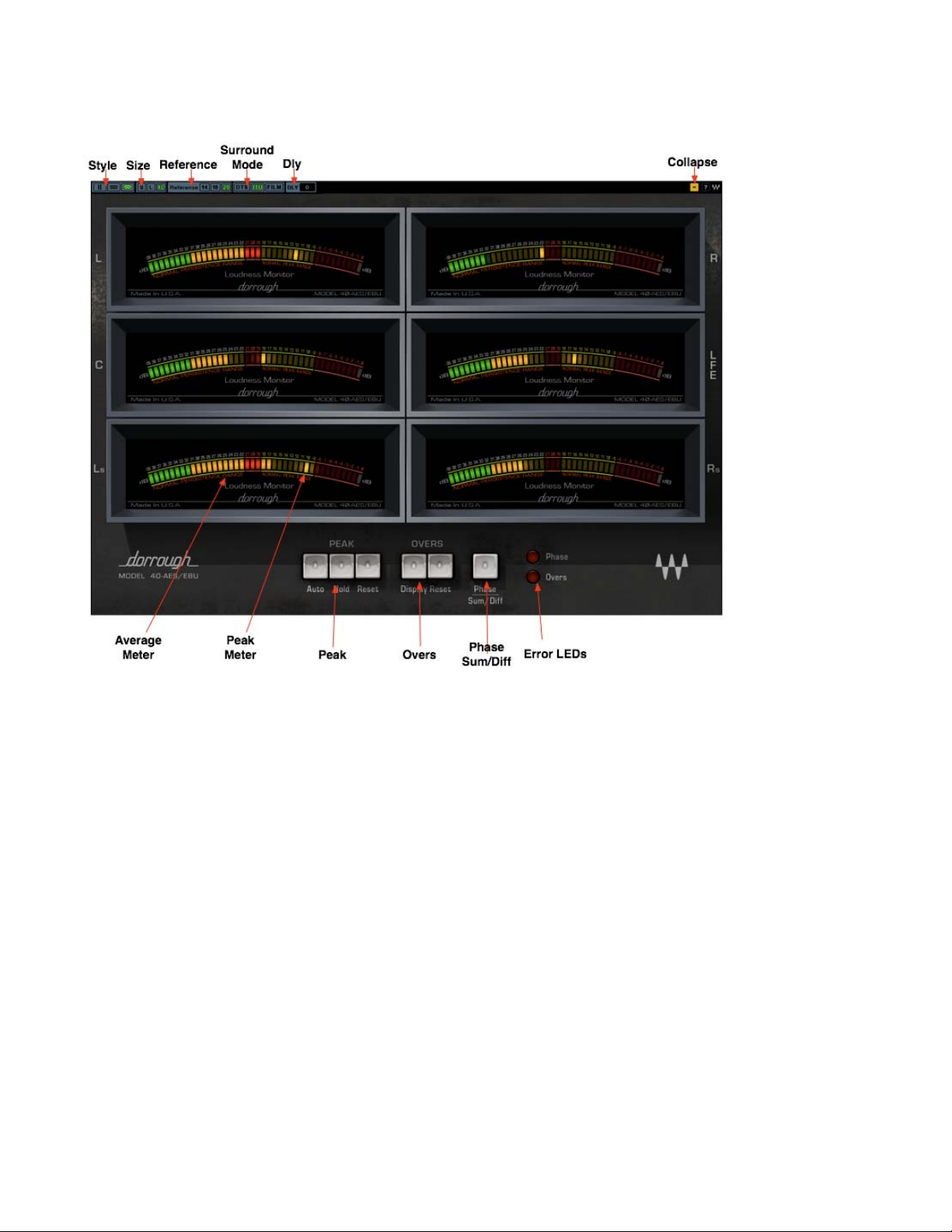
Chapter 3 – Interface and Controls
3.1 Interface
3.2 Dorrough Meter Controls
Style controls choice of meter style.
• Vertical (340/380)
• Horizontal (240/280)
• Arc (40 AES/EBU)
Size controls choice of meter size.
• Small
• Large
• Extra Large
The Waves Dorrough Meter Collection
User Guide
6
Page 7

Reference controls choice of reference level.
• 14 (0 VU = +4 dBu = -14 dBFS)
• 18 (0 VU = +4 dBu = -18 dBFS)
• 20 (0 VU = +4 dBu = -20 dBFS)
Although the meters are digital and display full scale metering, three reference levels are offered for
better orient
ation when working in conjunction w
ith analog devices.
The selection (-20,-18, or -14) represents a reference level o
f +4dBu, which is usually represente
d by
“0” on professional analog VU meters.
-20 dBFS is the Digital AES reference standard.
-18 dBFS is the Digital EBU reference standard.
-14 dBFS is commonly used in post-production and certain mastering situations.
Please note: Reference levels will only give you correct readings if your interface and analog devices
are calibrated to correct levels. Therefore, it is
imperative that your studio is calibrated.
Dly (Delay)
Range
0-50,000 samples
Resolution
500 samples steps
Due to I/O buffer distribution in certain host applications (e.g. Sound Forge, WaveLab, and Logic)
metering response may
precede the
audio coming out of your system. To compensate for this
possibility, we added a Delay control that allow synchronization of the meter display with the audio.
(This will not alter the input signal in any way.)
Do not change the Dly setting if you do not have sync problems between your audio and the
meter display.
Peak controls the peak display mode.
• Auto holds t
• Hold holds t
• Reset resets the peaks.
he peak for 3 seconds.
he peak for an infinite time.
When none of these modes is selected, the peak display will constantly refresh.
The Waves Dorrough Meter Collection
User Guide
7
Page 8

Overs
Like their hardware counterparts, Waves Dorrough meters are able to detect and display the
number of Overs, which are defined as 3 sample
s or more that exceed 0 dBFS (-0.0008 dBFS
@ 24bit).
• Overs Displa
• Overs Reset
y LED displays the number of Overs.
resets the Overs count to 0.
Meter Mode controls the
metering mode. (Stereo components only)
Left/Right displays Left and Right channel levels independe
•
• Sum/Diff (Sum and Difference) Left
/Upper meter displays the Sum of Left + Right; Right/Lower
meter displays the energy difference between Left and Right.
• Phase displays phase correlation be
o
0 LED indicates that the signal is 100% correlated (mono)
tween Left and Right.
o -39 LED indicates that the signal is 100% out of phase
o -20 LED indicates that the signal has random correlation
Readings b
-39 can be considered b
etween -20 and 0 can be considered good phase correlation; readings between -20 and
ad phase co
rrelation.
ntly.
The Waves Dorrough Meter Collection
User Guide
8
Page 9
3.3 Surround Edition Controls
The Surround Edition includes the Waves Dorrough Mono and Stereo meters, plus 5.0 and 5.1 channel
meters. Their controls are the same as those for
the addition of controls for Meter Order, Sum & Diff / Phase, and Collapse.
Meter Order controls th
surround sound industry. You can select between:
Film (Default)
5.0: L, C, R, Ls, Rs
5.0
5.1:L
5.0: L, R, Ls, Rs, C
5.1:
5.1: L, C, R, Ls, Rs, LFE
ITU
DTS
e layout of the meters according to
: L, R, C, Ls, Rs
, R, C, LFE, Ls, Rs
L, R, Ls, Rs, C, LFE
The Waves Dorrough Meter Collection
the Mono and Stereo meters as described above, with
common disciplines practiced in the
User Guide
9
Page 10

Sum & Diff / Phase Page
The Surround Edition plug-ins features a special single Sum & Diff / Phase page, which allows the
selection of channel pairs to be displayed on two sets of Sum & Diff / Phase Meters.
Please note:
The Waves Dorrough Meter Lt vs Rt mode is a bit different than the standard Dolby Lt / Rt matrix .
The Waves Dorrough Meter Lt vs Rt mode displays the sum of:
• 5.0
: Left + L
• 5.1: Left + L
eft Surround + 0.5 Center vs. Right + Right Surround + 0.5 Center
eft Surround + 0.5 Center + 0.5 LFE vs. Right + Right Surround + 0.5 Center +
0.5 LFE
Collapse (- / +) hides the control se
ction, leaving the meters displayed.
The Waves Dorrough Meter Collection
User Guide
10
Page 11

Chapter 4 – The WaveSystem
4.1 Interface Controls
Controls can be in one of three states:
• Not Selected where the control is
• Selected where the con
• Selected and Active where the control is the tar
trol is the target of mouse control entry only
Toggle Buttons
Toggle buttons display the state of a control, and allow switching between two or more states. Singleclick to cha
current setting, and others (bypass, solo, or monitoring toggles) illuminate when the control is active.
Some processors have l
adjustment while retaining the offset between the controls.
nge the control’s state. Some toggle buttons have a text display which updates with the
ink buttons between a pair of toggle buttons, allowing click-
not the target of any user entry
get for both mouse and keyboard entry
and-drag
Value Window Buttons
Value windows display the value of a control and allow clic
via the keyboard.
• Using the mouse, click-and-drag on the value window to adjust. Some value windows support
left/right, so
direction of movement that button supports).
• Using the arrow key
left/right (depending on the direction supported by that button) to move in the smallest
incremental steps across the button’s range (holding down the arrow keys will move faster
through the range).
• Using key
value from your keyboard. If you enter an out of range number, the button stays selected but
remains at the current setting (system beeps? If system sounds are on?)
Some processors have l
adjustment while retaining the offset between the controls.
me up/down (as you hover over a button, arrows will appear to let you know which
s, click once with mouse to select the button, and then use up/down –
entry, double click on the button to open the value window, and directly enter the
ink buttons between a pair of value windows, allowing click-
k-and-drag
adjustment, or direct control
and-drag
TAB Functions
TAB moves the ‘selected’ status to the next control, with shift-TAB moving in the reverse direction.
The Waves Dorrough Meter Collection
User Guide
11
Page 12

Additionally, the Mac has an option-TAB function for ‘down’ movement and shift-option-TAB for ‘up’
movement where
If you have several Value Window Buttons selected, TAB functions will take you through the selected
controls on
ly.
applicable.
The Waves Dorrough Meter Collection
User Guide
12
 Loading...