

Page 1
Manual - Technical Documentation
A
T
E
A
T
E
X
X
Watson-Marlow MasoSine – Pump
SPS 600
Revision 4.1 / March 2014
1
Page 2

Inhalt
Technical datasheet ..................................................................................................................................... 4
1 GENERAL ..................................................................................................................... 5
2 PURPOSE ..................................................................................................................... 5
3 FUNCTIONING PRINCIPLE .......................................................................................... 5
4 SAFETY INSTRUCTIONS ............................................................................................. 5
4.1 Basic safety instructions ..................................................................................................................... 5
4.2 Safety symbols ................................................................................................................................... 5
4.3 Obligation of the operator ................................................................................................................... 5
4.4 Organizational measures ................................................................................................................... 5
4.5 Obligation of the personnel ................................................................................................................ 6
4.6 Training of the personnel ................................................................................................................... 6
4.7 Informal safety measures ................................................................................................................... 6
4.8 Dangers when handling the machine ................................................................................................. 6
4.9 Safety measures in normal operation ................................................................................................ 6
4.10 Protective devices .............................................................................................................................. 6
4.11 Dangers due to hazardous pumped material ..................................................................................... 6
4.12 Dangers due to electrical energy ....................................................................................................... 6
4.13 Dangers due to hydraulic energy ....................................................................................................... 6
4.14 Special danger points ......................................................................................................................... 6
4.15 Constructional changes to the machine ............................................................................................. 7
4.16 Noise of the machine.......................................................................................................................... 7
4.17 Maintenance and repair, troubleshooting ........................................................................................... 7
4.18 Cleaning the machine......................................................................................................................... 7
4.19 Cleaning the machine......................................................................................................................... 7
4.20 Faults .................................................................................................................................................. 7
4.21 Use as intended ................................................................................................................................. 7
5 SAFETY INSTRUCTIONS (ATEX) ................................................................................ 7
5.1 Safety signs ........................................................................................................................................ 7
5.2 Pump classification ............................................................................................................................. 8
5.3 Zone classification .............................................................................................................................. 8
5.4 Classification of the ex-atmospheres ................................................................................................. 8
5.5 Ignition protection ............................................................................................................................... 8
5.6 Temperature classes .......................................................................................................................... 8
5.7 Limit values for the pump ................................................................................................................... 8
5.8 Grounding the pump........................................................................................................................... 8
5.9 Material properties .............................................................................................................................. 8
5.10 Pressure Conditions ........................................................................................................................... 8
5.11 Maintenance / Repair ......................................................................................................................... 9
5.12 Cleaning ............................................................................................................................................. 9
5.13 Medium to be pumped........................................................................................................................ 9
5.14 Coupling ............................................................................................................................................. 9
5.15 Drive ................................................................................................................................................... 9
6 WARRANTY AND LIABILITY ....................................................................................... 9
7 TRANSPORT INSTRUCTIONS ..................................................................................... 9
8 INSTALLATION........................................................................................................... 10
9 CONNECTION TO THE PIPING.................................................................................. 10
Revision 4.1 / March 2014
2
Page 3

10 POSSIBLE CONNECTION POSITIONS .................................................................. 10
11 CHANGING THE CONNECTION POSITION ........................................................... 11
12 CHANGING THE DIRECTION OF ROTATION ........................................................ 11
13 IMPORTANT: OBSERVE BEFORE START-UP! ..................................................... 11
14 PURGING ................................................................................................................. 12
14.1 Static purging device ........................................................................................................................ 12
15 CLEANING ............................................................................................................... 12
15.1 Cleaning in own circuit with water, alkali, acid ................................................................................. 12
15.2 Cleaning in the CIP circuit ................................................................................................................ 12
15.3 Manual cleaning ............................................................................................................................... 13
15.4 Sterilisation ....................................................................................................................................... 13
16 HEATING / COOLING .............................................................................................. 13
17 LUBRICATION ......................................................................................................... 13
18 DISPOSAL ............................................................................................................... 13
19 SPARE PARTS ........................................................................................................ 13
20 TAKING OUT OF SERVICE ..................................................................................... 14
20.1 Provisional taking out of service ....................................................................................................... 14
20.2 Final taking out of service ................................................................................................................ 14
21 TROUBLESHOOTING ............................................................................................. 15
22 SETTING DIMENSION ............................................................................................. 17
23 DISMANTLING ......................................................................................................... 18
24 ASSEMBLY .............................................................................................................. 19
25 DRAWINGS AND PART LIST .................................................................................. 23
25.1 Pump ................................................................................................................................................ 23
25.2 Part list of the pump ......................................................................................................................... 24
25.3 Sealing system „Mechanical Seal Assembly“ .................................................................................. 25
25.4 Parts list „Mechanical Seal Assembly“ ............................................................................................. 26
25.5 Sealing system „Mechanical Seal Assembly“ .................................................................................. 27
25.6 Parts list „Mechanical Seal Assembly“ ............................................................................................. 28
25.7 Sealing system „Lip Seal Assembly“ ................................................................................................ 29
25.8 Parts list „Lip Seal Assembly“ .......................................................................................................... 30
25.9 Dimensional drawing ........................................................................................................................ 31
Revision 4.1 / March 2014
3
Page 4

Technical datasheet
Please remove all technical information from the delivery note.
For spare parts ordering refer to software component list.
If you have problems to identify parts, please refer the drawing and parts list. In case of any questions please
contact the Technical Support.
Revision 4.1 / March 2014
4
Page 5
1 General
The operating instructions apply for the Watson-Marlow MasoSine Pump :
SPS 600
The operating instructions must be read before installing the pump. Please observe the safety instructions and the safety regulations.
2 Purpose
The purpose of your pump is defined exactly in the delivery note. The ATEX certification becomes null and void following any changes
to the purpose, including changes to components and materials. This is why you should always consult the manufacturer first!
3 Functioning principle
The functioning principle of the Watson-Marlow MasoSine is ingeniously simple. The pump consists of modular components. Because
of the sinusoidal form of the rotor, a chamber through which the product to be pumped is „pushed through“ or displaced is created four
times per revolution when running through the stator space.
As soon as a chamber closes, the opposite chamber opens by the same fraction of a millimeter as the closing chamber is contracted.
A suction and pressure characteristic of the pump free of pulsation results. The scraper prevents the pressure compensation of the
pressure to the suction side. At the same time the scraper undertakes the important function of forced lubrication of the pump bearings,
or when the pump is cleaned the intensive purging of the bearing or of the seal.
4 Safety instructions
4.1 Basic safety instructions
A basic requirement for safe handling and troublefree operation of this machine is knowledge of the basic safety instructions and of the
safety regulations.
These operating instructions contain the most important instructions to operate the machine safely.
These operating instructions, especially the safety instructions, must be observed by all persons who work on the machine.
Moreover the rules and regulations for accident prevention applicable at the place of use must be complied with.
The following safety instructions must be observed absolutely.
They are an essential and indispensable part of the user documentation. Non-compliance can result in loss of warranty claims.
It is recommended in the interest of all involved to enter all installation measures, maintenance, fault and repair cases, training courses,
instructions and special occurrences in a logbook assigned to the machine.
4.2 Safety symbols
Safety instruction which can cause danger for persons if not complied with
Safety instruction for electrical voltage
CCAAUUTTIIOONN
Safety instruction which can cause danger for the pump and is function if not complied with.
4.3 Obligation of the operator
The operator obligates itself to let only persons who are familiar with the basic regulations concerning working safety and accident
prevention and are instructed in handling the machine, as well as have read, understood and confirmed by their signature the warning
notes in these operating instructions to work on the machine.
The safety-conscious working of the personnel will be checked at regular intervals.
4.4 Organizational measures
The required personal protective equipment shall be provided by the operator.
All existing safety devices shall be checked regularly.
Revision 4.1 / March 2014
5
Page 6
4.5 Obligation of the personnel
All persons who are authorized to work on the machine obligate themselves to observe the basic regulations concerning working safety
and accident prevention before starting work, to read the safety chapter and the warning notes in these operating instructions and to
confirm by their signature that they have understood these.
4.6 Training of the personnel
Only trained and instructed personnel may work on the machine. The responsibilities of the personnel shall be defined clearly for
assembly, start-up, operation, setting, maintaining and repairing.
Personnel under training may work on the machine only under supervision of an experienced person.
4.7 Informal safety measures
The operating instructions must be kept constantly at the place of use of the machine. The generally valid as well as the local
regulations for accident prevention and environmental protection shall be provided and observed in addition to the operating
instructions. All safety and danger warnings on the machine shall be kept in legible condition.
4.8 Dangers when handling the machine
The Watson-Marlow MasoSine Pump is built according to the state of the art and the recognized safety engineering rules.
Nevertheless danger to life and limb of the user or third persons or impairments to the machine or to other assets can arise in its use.
The machine must be used only:
• for the intended use delivery note
• in perfect safety engineering condition.
Faults which can impair safety must be rectified immediately.
4.9 Safety measures in normal operation
Operate the machine only if all protective devices are fully functioning.
Before switching the machine on make sure that no one can be endangered by the starting machine.
At least once per shift inspect the machine for “externally detectable damage” and for functioning of the safety devices.
4.10 Protective devices
All protective devices must be attached correctly and functioning before every start-up.
Protective devices may be removed only
- after standstill and simultaneous protection against restarting the machine.
On delivery of part components the protective devices must be attached according to regulations by the operator.
If hot or cold machine parts can lead to danger, these must be protected by the operator on site against contact.
4.11 Dangers due to hazardous pumped material
In the case of hazardous pumped material (according to ArbStoffV) the corresponding regulations must be complied with.
4.12 Dangers due to electrical energy
Have work on the electrical supply performed only by an electrician. Check the electrical equipment of the machine
regularly. Rectify loose connections and scorched cables immediately.
Keep the control cabinet closed always. Access is allowed only to authorized personnel with key or tool.
If work on parts conducting voltage is necessary, call in a second person who switches off the main switch if
necessary.
If you make the electrical connection of the pump, act according to DIN EN 60204
Connect only by skilled personnel
4.13 Dangers due to hydraulic energy
Only personnel with special knowledge and experience in hydraulics may work on hydraulic devices.
Relieve the pressure in system sections and pressure lines to be opened before starting repair work. Replace hydraulic hose lines at
appropriate intervals, even if no safety-relevant defects are detectable.
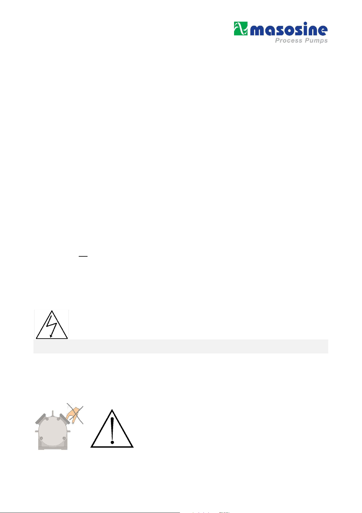
4.14 Special danger points
Rotating rotor in the pump. Danger of crushing or cutting off fingers and hands.
The pump must be protected by the customer so that it is not possible for persons to
grasp in the opening with the rotor running. In the case of work on the stationary rotor,
the drive must be secured against unintentional switching on.
Increased danger exists with dismantled pipes and opened pump.
Revision 4.1 / March 2014
6
Page 7
4.15 Constructional changes to the machine
Make no changes, attachments or conversions to the machine without approval of the manufacturer. All conversion measures require a
written confirmation of the Watson-Marlow MasoSine company. Immediately replace machine parts in not perfect condition. Use only
original spare and wearing parts. In the case of parts not obtained from MasoSine it is not guaranteed that they are designed and
manufactured in compliance with load and safety requirements.
4.16 Noise of the machine
The continuous sound pressure level proceeding from the machine is max. 70 dB(A). A higher sound pressure level that causes noise
deafness can arise depending upon the local conditions. In this case protect the operating personnel with corresponding protective
equipment / protective measures.
4.17 Maintenance and repair, troubleshooting
Perform specified adjustment, maintenance and inspection work on time. Inform operating personnel before starting the maintenance
and repair work. Protect all plant parts and operating media connected before and after the machine such as compressed air and
hydraulics and similar against unintentional start-up. In all maintenance, inspection and repair work switch the machine free of voltage
and secure the main switch against unexpected switching back on. Switch off the main switch and withdraw the key.
Attach a warning sign indicating that the switch must not be turned on again. Fasten and secure larger assemblies on
replacement carefully to lifting gear. Check loosened screw connections for firm seating. Use only original spare parts.
After ending the maintenance work check the safety devices for function.
4.18 Cleaning the machine
The bearings that are placed in the bearing housing of the pump wear off continuously which influences the run time. That is why both
bearings should be replaced after a certain amount of working hours. (see table below)
200 rpm 400 rpm 600 rpm
5 bar 10000 Std. 10000 Std. 10000 Std.
10 bar 10000 Std. 7238 Std. 4825 Std.
15 bar 3747 Std. 1873 Std. 1249 Std.
4.19 Cleaning the machine
Handle substances and materials used correctly, especially:
- when working on lubricating systems
- when cleaning with solvents.
4.20 Faults
In the case of operating faults switch off the machine and secure it against unauthorized or inadvertent starting up again.
4.21 Use as intended
The accurate intention is listed in the order confirmation.
Another use or use going beyond this is not as intended.
If you want to change the product, the pressure, the speed or the temperature, you must firstly consult the Watson-Marlow MasoSine
company or one of our representatives.
5 Safety instructions (ATEX)
Watson-Marlow MasoSine - Pump used in production machinery with explosive mixtures will be equipped accordingly in the factory.
5.1 Safety signs
Grounding symbol
Revision 4.1 / March 2014
7
Page 8
5.2 Pump classification
The pumps are only designed for jobs lasting several days and are therefore assigned to the Device Group II – Application field “dust –
or gas – explosive areas”!
5.3 Zone classification
The Watson-Marlow MasoSine Pumps can be used in explosive areas of the zone 1 / 21. This corresponds to the category 2 G / D.
It is expressly forbidden to use the pump(s) in the zone 0!
5.4 Classification of the ex-atmospheres
A distinction is made between dust and gas explosive atmospheres. In the model code, the atmosphere is abbreviated with G (Gas) and
D (Dust). Watson-Marlow MasoSine Pumps are only designed for the explosive atmospheres G (Gas) and D (Dust)!
5.5 Ignition protection
Our pumps are subject to ignition protection "c" constructive safety according to the standard for "non-electric appliances for use in
explosion-risk areas" EN 13463-5
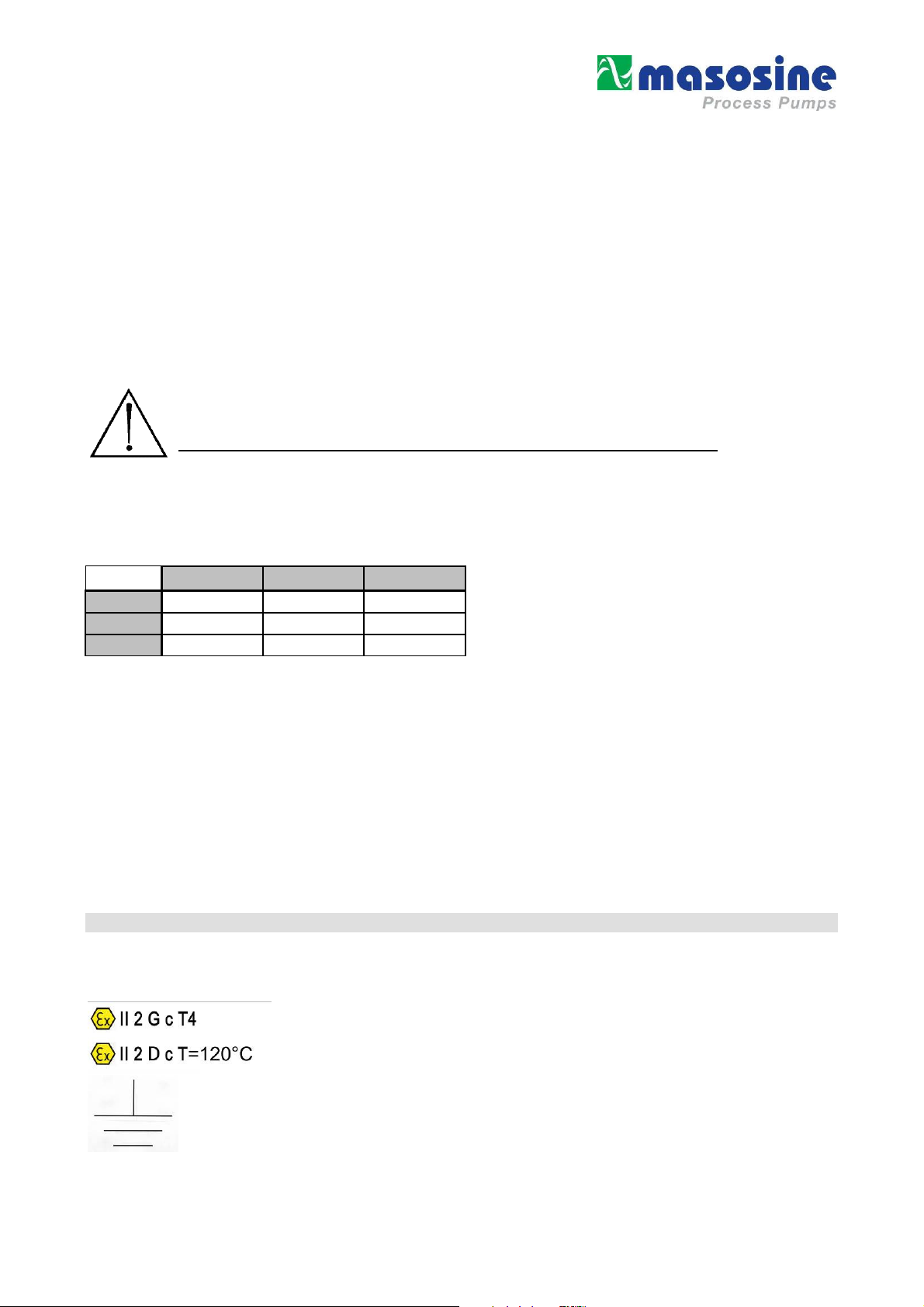
5.6 Temperature classes
-
EX II 2 G c T4
-
EX II 2 D c T=120°C
5.7 Limit values for the pump
The limit values for the pump (max. speed, max. pressure, max. temperature) are stated in the delivery note. These limit values must
never be exceeded under any circumstances! This applies in particular when using a frequency converter.
If the pumps are supplied without a drive, the following values apply!
SPS 600
max. Druck * 15 bar
max. Drehzahl * 600 UpM
max. Temperatur (T4) * 60°C
max. Temperatur (T3) * 120°C
Umgebungstemperatur -12°C bis +40°C
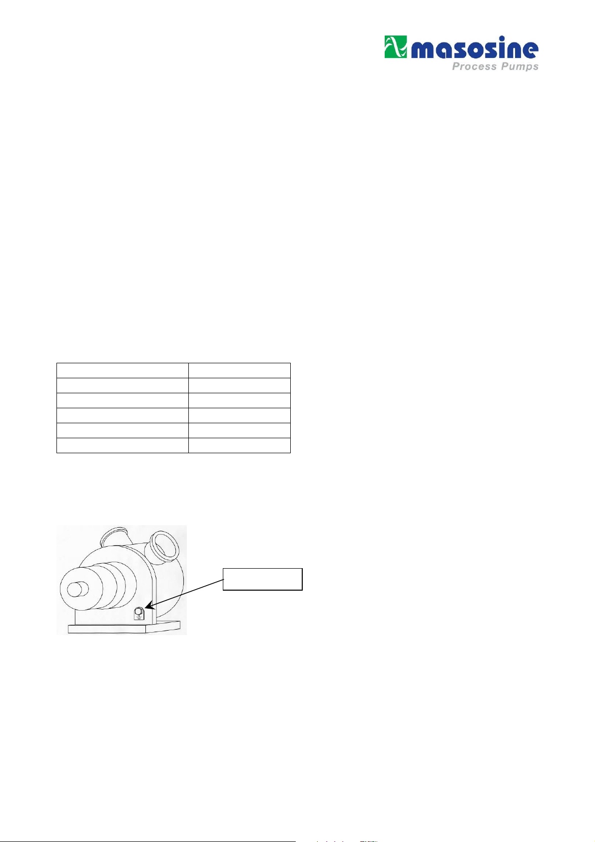
5.8 Grounding the pump
All supplied pumps are equipped with a grounding option.
In particular in ex-areas, the pump must be grounded by fixing a grounding cable to the corresponding position (see diagram).
In addition to the grounding of the pump, the motor also needs to be grounded! If the drive is not grounded, the pump aggregate may
not be operated.
Grounding
5.9 Material properties
Plastic parts that are fitted inside the pump react more to temperature changes that stainless steel parts. For this reason, the specified
maximum medium temperature (Tm=100°C), for which the pump is designed, may not be exceeded. If the specified temperature is
exceeded, this may cause a linear expansion and may block single components; this in turn could cause the pump to fail or could result
in damage to parts of the pump. Also, excessive temperatures can accelerate the wear of dynamic parts and therefore reduce the
lifespan of the plastic parts.
Corrosion may occur to the Power Frame of the pump if the paintwork is damaged. Corrosion represents a hazard for the use of pumps
in explosive areas (for measures, see Troubleshooting Chap. 21).
5.10 Pressure Conditions
To avoid any over-pressure in the pump as a result of a closed pressure line, a pressure controller must be installed.
Revision 4.1 / March 2014
8
Page 9
5.11 Maintenance / Repair
• The Filling of the pump is only permitted outside the explosion aria. Tools that are used should in compliance with ATEX.
• The pump aggregate always needs to be kept clean of dust with a damp cloth to prevent the dust from smouldering.
• The rinsing channels in the power frame must always be checked for blockages and if necessary cleaned.
5.12 Cleaning
Caution! No solvent cleaning agents may be used to clean the pump as this could create an uncontrollable explosive atmosphere.
5.13 Medium to be pumped
Chemicals that are combustible below the temperature 120 degrees Celsius and Carbon disulphide must not be pumped.
5.14 Coupling
If the pump is used in an explosion-risk area, the pump must only be coupled to the drive by means of an elastic, positive coupling with
ATEX certification, at least corresponding to the supplied pump. Chains, toothed belts, v-belts or similar equipment which may transmit
radial forces on the bearings should not be used.
5.15 Drive
Any preceding reduction gears and/or control units must have the corresponding ATEX certification, at least corresponding to the
supplied pump. Combustion engines must never be used!
For operation with a frequency converter, this must either be installed outside the ex-zone, or have the same ATEX certification
corresponding to the delivered pump. In any case the converter must have the properties required for operation in ex-zones, for
example, temperature monitoring, speed limitation, etc.
6 Warranty and liability
Basically our “General sales and delivery conditions” apply.
These are available to the operator at the latest since conclusion of the contract.
Warranty and liability claims for personal and material damage are excluded if they are attributable to one or several of the following
causes:
• Use of the machine not as intended
• Incorrect installation, operation and maintenance of the machine
• Operating the machine with defective safety devices or not correctly attached or not functioning safety and protective devices
• Non-compliance with the instructions in the operating instructions regarding
transport,
storage,
installation,
start-up,
operation, maintenance and setting of the machine.
• Unauthorized constructional changes to the machine
• Insufficient monitoring of machine parts subject to wear
• Incorrectly performed repairs
• Cases of catastrophe due to effect of foreign bodies and acts of God.
Watson-Marlow MasoSine grants no warranty on this documentation as well as no implicit warranties on customary quality and
suitability for a certain application.
The Watson-Marlow MasoSine undertakes no liability for errors contained in it or consequential damage occurring by chance arising
due to the design, performance and the use of this documentation.
This publication contains own information protected by copyright. All rights are reserved.
This publication may be neither photocopied, nor duplicated nor translated without previous agreement of The Watson-Marlow
MasoSine. Rights reserved to make changes in these operating instructions.
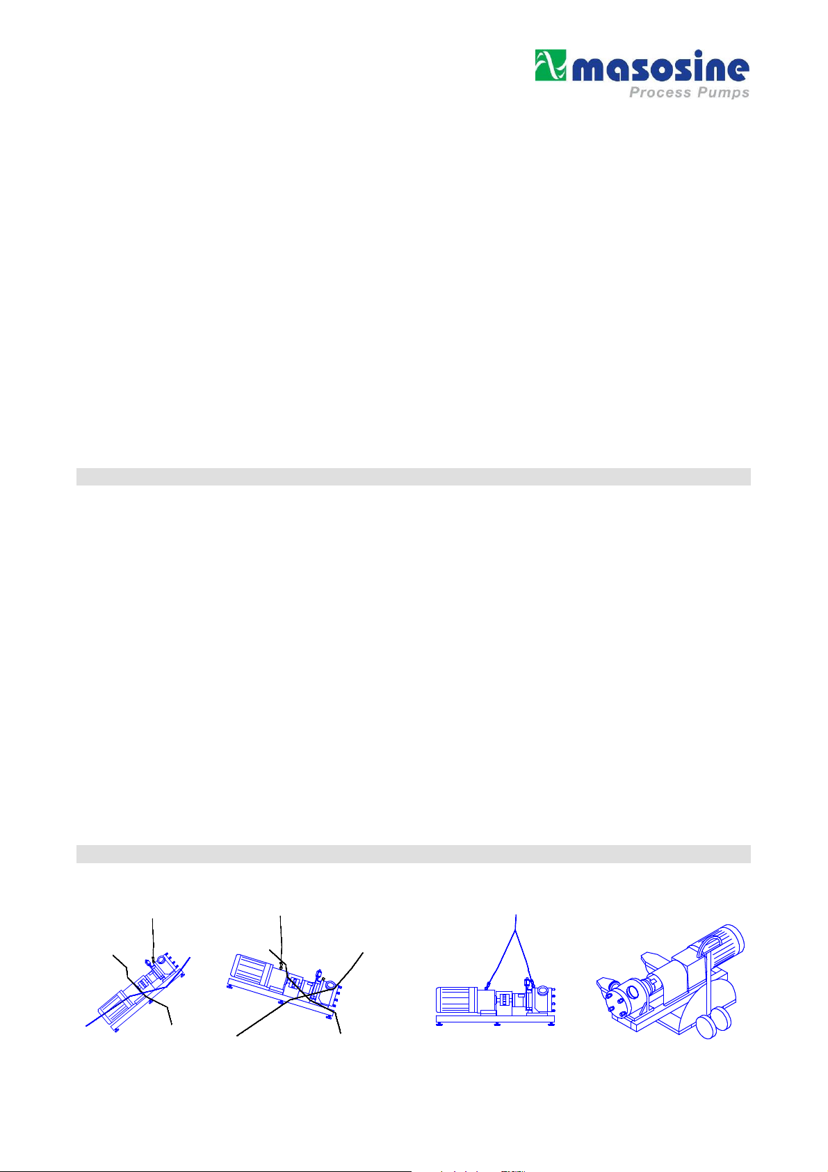
7 Transport instructions
The choice of the means of transport is according to the size of the pump and of the drive. The pump must be suspended correctly for
transport. The crane/forklift truck and the ropes/belts must be sufficiently dimensioned. If the pump is transported with a lift truck or a
forklift truck, it must be noted that the console centre point is not automatically the centre of gravity.
wrong right
Revision 4.1 / March 2014
9
Page 10
8
CCAAUUTTIIOONN
CCAAUUTTIIOONN
CCAAUUTTIIOONN
CCAAUUTTIIOONN
CCAAUUTTIIOONN
CCAAUUTTIIOONN
CCAAUUTTIIOONN
Installation
The motor shaft and pump shaft connection
must be protected against contact!
DO NOT START WITHOUT PROTECTION AGAINST CONTACT!!
Place the pump on a level ground.
Do not start without the protection against contact!!
The foundation should be dimensioned sufficiently for the weight of the pump.
There should be sufficient space for maintenance work around the pump.
It must be guaranteed that the motor receives an adequate air supply.
If the pump is used in explosion endangered rooms, an Ex protected motor must be used.
The total unit must be protected against static charge.
Align the shaft of the pump with the shaft of the drive.
9 Connection to the piping
wrong
Before connection clean the piping and remove foreign bodies.
(e.g. there can still be residues in the pipes due to welding work).
Fit elastic intermediate members (compensators) between pump and fixed piping on the suction
and pressure side. This should prevent vibrations of the pump being transmitted to the piping system.
Forces and torques acting from the piping on the pump connections (e.g. due to distortion, expansion due
to temperatures etc.) must be avoided.
The pressure line should point upwards, so that later residual liquid can always flow back into the pump.
Thus total dry running is avoided. Further it facilitates the later suction process.
The operator has to ensure that an inadmissible pressure rise (above the pressure agreed in the order
and listed in the technical data) is not possible.
The Watson-Marlow MasoSine pumps normally run with such a low resonant frequency that no
corresponding damage is caused. However, particularly when running with converters, certain frequencies
can cause interfering vibrations which must be avoided. It is important during initial commissioning to
ascertain whether such vibrations exist and to define them accordingly, so that the frequency converter
can then be programmed to avoid these frequencies. Similarly, interference from cavitation or rigid lines
must be ruled out.
The operator has to ensure that the pump can work free of cavitation.
Cavitation destroys the pump
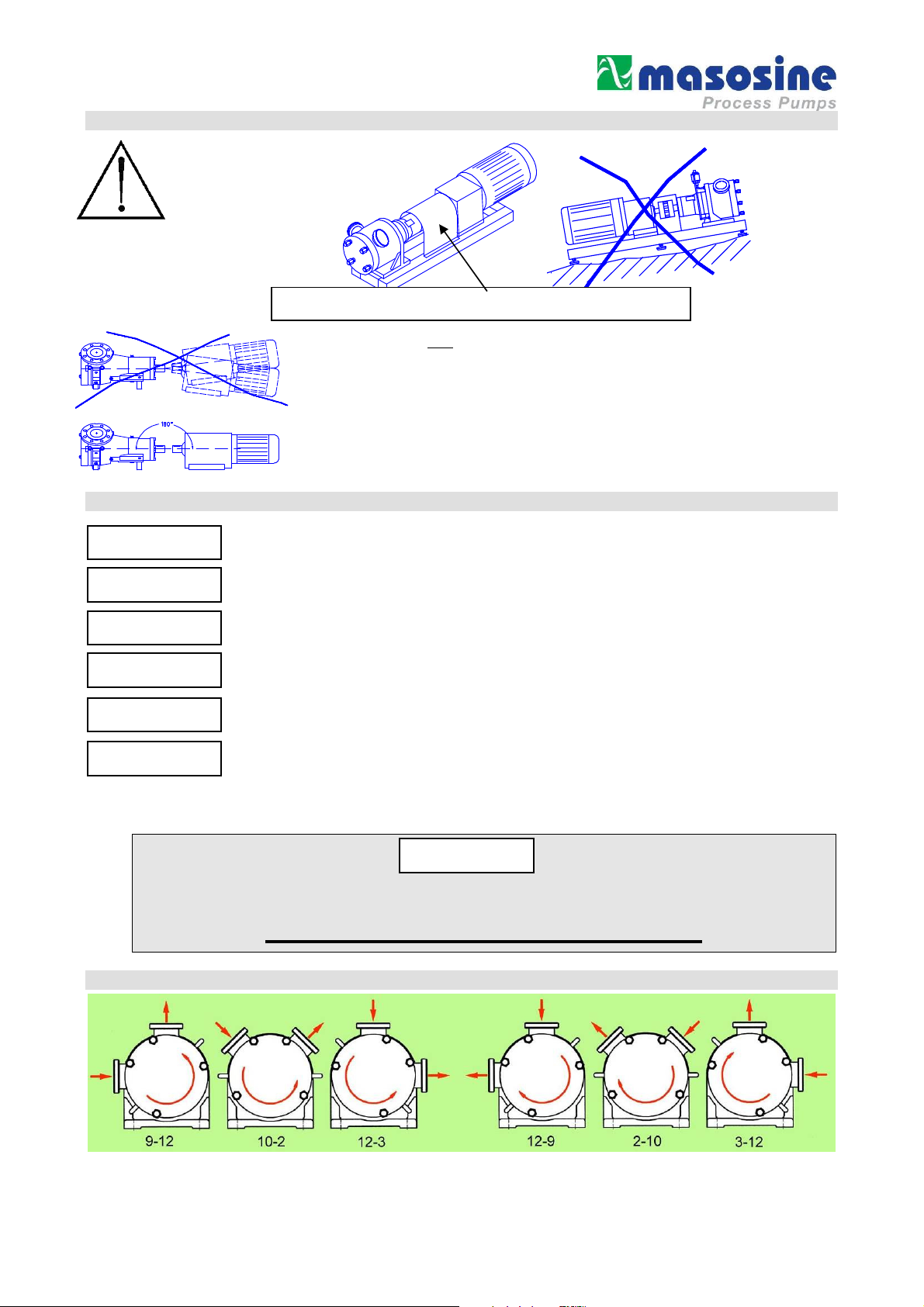
10 Possible connection positions
Counterclockwise rotation of the rotor and motor Clockwise rotation of the rotor and motor
Unless otherwise ordered, the pump is delivered in position 10 - 2
Revision 4.1 / March 2014
10
Page 11

11 Changing the connection position
Let the change of direction of rota
tion on the drive be made only be trained skilled
When the nozzle orientation is changed, the motor must be protected against
Remove the screws on the bearing block. Turn the housing by an angle of 45° to the left or right.
Tighten the screws again. (with 45 Nm)
However, take care that due to the corresponding arrangement of the pressure line in the pump, a certain
residual amount remains. By this measure you make it easier for the pump to draw in highly viscous products.
However, in the case of horizontally lying pressure connection you must absolutely take care that the pressure
line is run so that the pump is always covered with residual liquid.
In this way total dry running is avoided.
unintentional switching on!
12 Changing the direction of rotation
The suction or the pressure side changes on
changing the direction of rotation of the drive.
Then the gate and the gate guide must
absolutely be turned, since other-wise the pump
cannot bring its full output. If the direction of
rotation is changed, the rotation direction arrows
must be turned correspondingly. Further the
suction or pressure connection must be marked.
The set direction of rotation is stated by an arrow.
The pump can run against the set direction only
for a short time. It cannot build up more than 2
bar pressure if the direction of rotation is wrong.
personnel. The motor must be protected against unintentional switching on!
13 Important: Observe before start-up!
If you have performed cleaning or repair work or make the first start-up, check before start-up that all screws are correctly and
completely tightened.
The pump can possibly be contaminated by transport, therefore remove the front cover and clean if necessary before start-up.
Before you start up the pump, convince yourself once again that the gate and the gate guide are in the correct position in relation to the
pressure side (see change of direction of rotation).
Observe the corresponding regulations in the case of hazardous pumped material (according to ArbStoffV).
The operator must ensure that the pump is installed in an appropriate position with all necessary safety
CCAAUUTTIIOONN
precautions (sensors, switches, pressure gauges, etc.)!
Liquid level
The pump must always be filled with the corresponding
medium before commissioning and during operation,
with the liquid level above the rotor (see diagram).
The filling of the pump should be done outside the
combustible area.
When the pump runs dry, the
temperature limit for the explosive area
is exceeded!
Revision 4.1 / March 2014
11
Page 12

CCAAUUTTIIOONN
CCAAUUTTIIOONN
CCAAUUTTIIOONN
Choke
X
- bar
X + 3 bar
The motor must be connected by an expert according to DIN EN 60204.
Make sure before start-up that all valves on the pressure and suction side are open. The pump may not
pump against a closed valve without overpressure valve.
If the pump leaks, end operation as quickly as possible to replace the damaged sealing elements.
The operator must ensure that the pump can work free of cavitation.
Cavitation destroys the pump.
14 Purging
• The purging medium must correspond at least to the quality of pure drinking water. Under no circumstances may it be
contaminated by particles (sand or other dirt). This would automatically lead to failure of the seals.
We also recommend using transparent plastic pipes as purging piping.
• Purging should be without pressure, i.e. the purging water running out should run out from the purging system without pressure
(thumb test: it must be possible to stop water with the thumb).
• To protect the pump against running dry, fill this with some water, possibly through a separate filling valve fitted on the suction or
pressure pipe.
Fill a suitable
liquid above
Liquid level
14.1 Static purging device
Before start-up you must fill the purging device (if also ordered) with a suitable purging
liquid (depending upon the product to be pumped).
The purging liquid is filled into the sight glass above through the folding lid until the liquid
level in the sight glass is just below the bent outlet of the pipe.
The pump is rinsed without pressure, e.g. the draining rinsing water should be allowed to
drain out of the system without pressure (thumb test: it must be possible to stop the water
with your thumb).
15 Cleaning
All Watson-Marlow MasoSine Pumps are fully capable of CIP cleaning. Please observe our CIP cleaning regulations.
15.1 Cleaning in own circuit with water, alkali, acid
1. Set control gear to maximum speed (at least 400 rpm).
2. Choke after the pump so that a counterpressure of 3 to 4 bar arises.
3. Should the required cleaning effect not be achieved after this process,
it is necessary to dismantle the pump.
This is done in a few minutes as described in detail in the operating instructions.
Manual cleaning of the pump can be performed after complete dismantling of the pump.
Pay attention to parts sensitive to breakage!!
15.2 Cleaning in the CIP circuit
back to the plant
Valve
Open / Close Valve
from CIP plant
Revision 4.1 / March 2014
1. Purging surge
Open the choke valve and let the Watson-Marlow MasoSine Pumps
run with maximum speed to perform the first rough cleaning.
2. Purging
S
et the choke valve so that the pressure side of the pump is at least
3.0 bar higher than the suction side.
Open the open/close valve to guarantee cleaning of the series
connected devices.
12
Page 13

Watson
-
Marlow MasoSine
15.3 Manual cleaning
Manual cleaning of the pump can be performed after complete dismantling of the pump.
Pay attention to parts sensitive to breakage!!
If the pump is stopped during the process and opened for the purpose of cleaning or checking,
the responsible fitter or electrician must be notified to undertake suitable measures so that the pump
cannot be put into operation (remove fuses, notify electrician).
The pump may also never be put into operation if the housing cover is removed. Should the pump
not yet be connected to the piping system, then reliable care must be taken that the drive machine
cannot be switched on.
Observe the accident prevention regulations!!
15.4 Sterilisation
Sterilization of the pump with standard equipment is possible up to 110°C only in standstill!
In the case of special equipment of the pump or higher temperatures, please always firstly consult the manufacturer!
16 Heating / cooling
Front housing Pump housing
There is a crescent-shaped channel milled into the
housing which is sealed later by a stainless steel
plate. There are connections on two sides through
which the heating or cooling agent flows. Counterpressure should not exceed 1 bar. You can dictate
temperature and pumping rate by the heating or
cooling agent.
The cooling/heating agent should enter the
system at the lowest point.
If a heater is to be used at the pump, the
temperature must be clarified with the
17 Lubrication
The first filling with a corresponding grease lubricant (such as
MOLYDUVAL Soraja C532, DIN 51502, +180°C to –20°C
according to FDA Reg. 21CFR178.3570 or ESSO
multipurpose grease NLGI K2-K30) is made at MASO.
However, the filling amount should be checked regularly and
replenished if necessary. For this purpose unscrew the vent
valve and refill with grease through the lubricating nipple - until
it escapes through the vent bore. If the valve is not
unscrewed before this process, damage to the radial shaft
sealing rings cannot be ruled out! After ending filling simply
screw the vent valve back on!
18 Disposal
Send the used oil or used grease for recycling.
19 Spare parts
Basically repairs should be performed only by factory personnel or by customer service organizations authorized by the factory. If you
perform the work yourself, observe the relevant safety regulations and contact the factory customer service before starting the work,
especially if there are still warranty obligations that can be lost due to not approved interventions.
Only original Watson-Marlow MasoSine spare parts may be used.
You should record changes in the fixtures and fittings, for example another sealing
system or a material change, in writing.
Please provide all information on orders:
- Pump number - Material
- EDP number - Quantity
- Article Ask for our express delivery !
Postfach 100
Steinbeisstraße. 3
D-74358 Ilsfeld (Germany)
Telefon : +49 (0)7062 9560-0
Fax : +49 (0)7062 64593
EMail : Info@masosine.com
Internet : http://www.masosine.com
Revision 4.1 / March 2014
13
Page 14

20 Taking out of service
20.1 Provisional taking out of service
Short-term:
Remove product residues (cleaning) Switch main switch off Clean pump surface
Longer-term:
Remove product residues carefully (cleaning) Switch main switch off Clean pump surface Separate connections Drain off
static washing liquid Loosen washing connections.
20.2 Final taking out of service
Separate the power and washing liquid supply. Send oils and greases for recycling.
If you send the remaining parts to us carriage paid, we will dispose of the parts.
Revision 4.1 / March 2014
14
Page 15

21 Troubleshooting
Error Cause Remedy
Pump does not draw in
Pump does not deliver
Pump is noisy
Pump leaking at leakage
hole
Pump leaking at the front
housing
Pump has blocked
Strong wear after short
operating time
Direction of rotation not correct Check direction of rotation
No wetting liquid in the pump Fill pump with liquid
Screw fastening not tight Check screw fastening
Suction pipe too long Adapt suction pipe
Pipe cross-section too narrow Adapt suction pipe
Shaft seal leaking Check all seals for damage
Wear in the pump Change wearing parts
Motor speed not correct Measure, regulate speed
Gate and Gate Guide wrongly
inserted
Direction of rotation not correct Check direction of rotation
Suction and pressure pipe confused Check pipe system
Motor speed not correct Check speed based on output
Wearing parts worn Replace wearing parts
Gate and Gate Guide wrong Check position (see changing
Inserted closed gate valve Check pipe system
Noises come from the drive Consult
Noises come from the pump Consult
Suction pipe too small (cavitation) Shorten suction pipe or increase
Knocking noises from the pump
head
Noises from power frame Fill oil, change tapered roller
Coupling not aligned Align coupling with hairline
Sealing system is leaking Change seal faces, static /
O-ring seal leaking Replace O-ring
Radial shaft sealing ring on the
power frame leaking, oil escapes
Housing seal not or wrongly installed Install housing O-ring correctly or
Housing seal defective Install housing O-ring correctly or
Foreign body in the pump Remove foreign body, examine
Power supply interrupted Check electrical installations
Defect on the drive (Separate the coupling and turn
Solids in the pumped material
Pumped material is abrasive
Check position (see changing
direction of rotation)
diagrams
direction of rotation)
Watson-Marlow MasoSine
Watson-Marlow MasoSine
diameter, reduce speed
Gate valve wear
bearings
dynamic or lip seals
Dismantle power frame,
replace lip seals
replace
replace
pump for damage
(fuses), check drive
the pump by hand)
Frequent change of the wearing
parts, change material pairing,
reduce speed
Revision 4.1 / March 2014
15
Page 16

Error Cause Remedy
Rotor has wear on one side
Pump not clean after CIP
cleaning
Rotor has seized on Liner
Purging between housing
and Power Frame leaking
Water or pumped material
in the Bearing Housing
Front Support has seized
on Rotor
Product is leaking from the
Bearing Housing openings
Rotor not tightened correctly on
installation
Adjusting dimensions changed after
working on the Bearing Housing
Cleaning regulation not complied
with
Rotor not correctly tightened Tighten Shaft Nut firmly on block
Temperature too high
(thermal expansion)
O-ring in the power frame missing or
defective
Purging pressure too high Purging must be pressureless
Leakage bores closed Check leakage bores for free
O-ring in the front bearing missing or
worn
Front bearing wrongly installed Examine front bearing for
Sealing system in the pump is
leaking
Tighten Shaft Nut firmly on block
Check and correct the adjusting
dimensions
SPS 600 = 27,5 mm + 0,1 mm
Choke on the pressure side
Check differential pressure 3-4
bar
Choose Liner with larger
tolerances
Install or replace O-ring
(attach pressure reducer, max.
0.1 bar)
passage, replace shaft seals on
pump and power frame
Install or replace O-ring
damage and install in correct
position
Inspect and if necessary replace
the sealing system and clean the
rinsing channels
Pump aggregate subject to
vibrations
Smells and smoke coming
from the pump
Corrosion
Speed of the (drive) motor is too
high
Pump is running dry
Corrosion occurs
Lower the speed of the (drive)
motor
Stop the pump immediately.
Check inner parts for damage
and replace if necessary
Eliminate corrosion and varnish
or use spray oil
Revision 4.1 / March 2014
16
Page 17

22 Setting dimension
The setting dimension of 27.5mm (see diagnostic aid) is measured at the place X.
If the dimension is too small, turn down on the setting ring.
If the dimension is too large, you should contact the factory and order a new setting ring
Revision 4.1 / March 2014
17
Page 18

23 Dismantling
Inform electrician!
Disconnect drive unit from mains!
Secure against being accidentally
switched back on!
Undo the 3 cap screws Item 40 and remove the front
bearing housing cover Item 49. Release the tabwasher Item
44.
Undo and remove the locking screw Item 45.
Undo the 3 cap screws Item 51 and remove them.
The front bearing housing Item 52 can then be pulled off the
carrier shaft Item 24 together with the spacer sleeve Item
54.
The innards of the pump are now in front of you.
I.e., you can see the gate guide, the gate, the shaft
sleeves, the rotor and the two halves of the liner.
ATTENTION!
When dismantling please ensure that the pump
parts, especially the internal parts and the seals are
not damaged.
You can now pull off the complete front sealing
system from the shaft. Remove the front half of the
liner from the pump housing.
The rotor Item 34, the gate Item 8 and the gate
guide Item 5 are pulled off the pump shaft Item 24,
or the pump housing Item 32 as a single unit.
Here too you should have another
person to help you, one person
should protect the gate guide from
falling and the other the rest.
Remove the flushing pipes from the flush ports. Undo and
remove the lock nut Item 56 from the pump shaft.
Undo and remove the 6 cap nuts Item 4, which hold the
front cover to the pump housing.
Once the cap nuts have been removed, with the help of a
second person you can remove the front cover from the
pump housing, by pulling it off horizontally via the studs
Item 38.
The two front cover pins Item 59 help you to grip the
housing.
Attention:
The front housing is very
heavy!!! (Approx. 60 kg)
The remaining parts and the second half of the liner
can also be axially pulled from the shaft or the pump
housing.
If you also want to replace the sealing fixture, or the
lip seals, it might be necessary to unscrew the pump
housing Item 32.
To do this you should use the special assembly tool
from Watson-Marlow MasoSine.
Attention: The pump housing
is very heavy and must not
fall onto the shaft!
Revision 4.1 / March 2014
18
Page 19

19
24 Assembly
The pump is assembled in exactly the reverse order. All parts
of the pump now lie in front of the pump on a soft base.
You see that dismantling was very easy.
If you now start with the installation and assembly of the pump,
please take care that the sealing lips of the lip seals are not
damaged.
If you have the impression that the O-ring or indeed all other Orings are damaged, replace these by new parts.
Push the rear half of the liner into the pump housing. The rotor,
gate and gate guide are pushed as pre-assembled unit into the
pump housing. Please note that the bore hole in the front of the
rotor points towards you!
To simplify assembly we suggest that you apply a suitable oil or
grease to the pump shaft. Push on the rotor sleeve coupling
Item 36 so that the larger fixing pin engages in the bore hole of
the rotor. Then push the shaft sleeve Item 74 onto the stop so
that the fixing pin engages in the bore hole of the rotor sleeve
coupling Item 36.
Remove the feather key Item 50 from the shaft.
Screw the lock nut Item 56 on the shaft stump and tighten this
(with a special tool) with approx. 200 Nm, to guarantee axial
clamping of shaft sleeve and rotor. For security tighten all
screws in the lock nut with 10 Nm!
Caution! Refit the feather key No. 50 and screw this tight!
Push the second half of the liner up to the stop into the pump
housing.
Push the front cover Item 37 (with sealing holder and sealing
rings), guided by the studs, onto the pump housing. Take care
that the housing gasket is in the correct position. Here as well if
you think that the gasket is damaged, replace it!
Screw the 6 cap nuts onto the studs and tighten these
uniformly and firmly, so that the front cover is connected firmly
with the pump housing.
Then push on the front bearing housing. Take care that the
feather key screwed firmly in the shaft sits in the slot of the
spacer sleeve provided for it!
Tighten the 3 Allen screws, fit the front cover and tighten this
firmly.
Special –
tool
Revision 4.1 / March 2014
Page 20

20
tightened with a
Cap
screw
The pin must fit
in the bore of
the rotor
Push the rotor, the gate and the gate guide as one unit into the
housing. Make sure that the gate guide and the gate are in the
correct installation position. (Refer to the ROTATION
DIRECTION CHANGE chapter)
The bore in the rotor must look to the front.
To loose the lock nut
please do not fully
unscrew all 12 screws
Optional tool S60-9006-25
The pin must
fit in the bore
of the rotor
The lock nut at
pos. 56 is
special tool
with a torque of
200 Nm.
Then tighten all
screws on the
adjusting nut
with a torque of
10 Nm.
Revision 4.1 / March 2014
Page 21

21
Revision 4.1 / March 2014
Bend the tab
washer
Page 22

22
Please pay attention, that the O-rings are
assembled completely and without
defects !
If you have any questions, give us a call.
We will be pleased to help you.
Watson-Marlow MasoSine
Postfach 100
Steinbeisstraße. 3
D-74358 Ilsfeld (Germany)
Telefon : +49 (0)7062 9560-0
Fax : +49 (0)7062 64593
EMail : Info@masosine.com
Internet : http://www.masosine.com
Revision 4.1 / March 2014
Page 23

23
25 Drawings and part list
25.1 Pump
Revision 4.1 / March 2014
Page 24

24
25.2 Part list of the pump
Pos Qty EDP-No.
1 2 S60-9002-12 Threaded Plug 32 1 S60-0300-10 Pump Housing
2 2 S60-0622-__ O-ring 33 4 S60-0682-12 Cap Screw
3 1 S60-0601-10 Shaft Sleeve Pin 34 1 S60-0100-10 Rotor
4 6 S60-1600-12 Front Cover Cap Nut 35 2 S60-1200-__ Liner
5 1 S60-0700-10 Gate Guide 36 1 S60-0651-10 Rotor Sleeve Coupling, front
6 1 S60-1701-__ O-ring, Front Cover 37 1 S60-0200-10 Front Cover
7 2 S60-4100-__ O-ring 38 6 S60-1800-12 Front Cover Stud
8 1 S60-0400-__ Gate 39 2 S60-2500-__ O-ring
9 1 S60-0612-10 Rotor Sleeve Coupling, rear 40 3 S60-4700-12 Cap Screw
10 2 S60-0632-10 Pin 41 1 S60-4400-__ O-ring
11 1 S60-3900-25 Lifting Eye Screw 42 1 S60-1501-12 Grease Nipple
12 2 S60-0504-34 Flush Port 43 1 S60-9030-50 cover, shaft nut
13 1 S60-1305-10 Power Frame Spacer 44 1 S60-1002-12 Tabwasher
Description
Pos Qty EDP-No.
Description
14 1 S60-1301-__ Power Frame 45 1 S60-1001-12 Cap Screw
15 4 80-0129-12 Cap Screw 46 1 S60-4600-25 Snap Ring
16 1 80-1521-50 Vent Valve 47 1 S60-1502-__ Lip Seal
17 1 S60-2901-__ O-ring 48 1 80-1521-59 Vent Valve
Front Bearing Housing
18 1 S60-1501-12 Grease Nipple 49 1 S60-1403-10
19 1 S60-2600-25 Ball Bearing 50 1 S60-3201-10 Shaft Key, front
Tabwasher, Bearing Lock
20 1 S60-2700-25
21 1 S60-3100-__ Lip Seal 52 1 S60-1400-10 Bearing Housing, front
22 1 S60-2800-25 Bearing Lock Nut 53 1 S60-9000-12 Set Screw, Shaft Key (front)
23 1 S60-3202-25 Shaft Key, rear 54 1 S60-4500-10 Spacer Sleeve
24 1 S60-1000-16 Pump Shaft 55 2 S60-4501-10 Spacer Ring
25 1 S60-1500-__ Bearing Housing Cover 56 1 S60-5201-58 Lock Nut MS
26 4 S60-2900-12 Cap Screw 57 1 S60-1401-__ Lip Seal
27 1 S60-2310-20 Adjusting Ring 58 1 S60-2401-25 Cylinder Roller Bearing
Nut 51 3 S60-4800-12 Cap Screw
Cover
28 1 S60-3700-__ O-ring 59 2 S60-5000-12 Front Cover Pin
29 4 S60-1900-10 Housing Mounting Bolt 60 1 S60-0310-30 Supporting Wedge
30 2 S60-2300-__ Lip Seal
31 1 S60-3700-__ O-ring
Revision 4.1 / March 2014
X
1 Sealing System, front
Y
1 Sealing System, back
Please ensure you quote the pump number when ordering spare parts! (See cover sheet or data sheet)
Page 25

25
25.3 Sealing system „Mechanical Seal Assembly“
Revision 4.1 / March 2014
Page 26

26
25.4 Parts list „Mechanical Seal Assembly“
Pos Qty
90 2 S60-4100-__ O-Ring
91 1 S60-5106-10 Shaft sleeve, back, coated
92 2 S60-5123-41 Stationary seal ring
93 1 S60-5107-10 Stationary seal ring holder support, back
94 2 S60-0502-34 Backing ring
95 4 S60-0501-80 Radial shaft seal
96 1 S60-4900-34 Backing ring
97 1 S60-3700-__ O-Ring
98 1 S60-1305-10 Pump bracket frame-distance
99 1 S60-3700-__ O-Ring
100 2 S60-4100-__ O-Ring
Part No. Description
101 2 S60-5110-__ O-Ring
102 2 S60-5122-41 Rotating seal ring
103 2 S60-5103-10 Pressure ring
104 2 S60-5108-__ O-Ring
105 2 S60-5109-__ O-Ring
106 1 S60-5115-10 Shaft sleeve, front
107 1 S60-0613-10 Tappet (pin)
108 2 S60-5500-__ Bearing for mechanical seal
109 4 80-0211-25 Pint
110 1 S60-5101-10 Stationary seal ring holder support, front
111 1 S60-0516-34 Distance (ring)
oder Lieferschein)
Bitte geben Sie unbedingt die Pumpennummer bei der Ersatzteilbestellung an! (siehe Deckblatt
Revision 4.1 / March 2014
Page 27

27
25.5 Sealing system „Mechanical Seal Assembly“
Revision 4.1 / March 2014
Page 28

28
25.6 Parts list „Mechanical Seal Assembly“
Pos Qty
70 4 S40-9000-__ Lip Seal
71 16 S60-5410-15 Pressure Spring
72 1 S60-5455-10 Static Seal Ring Holder, Front
73 4 S60-5464-12 Driving Pin
74 1 S60-5456-10 Impeller Ring Housing, Front
75 1 S60-5476-10 Impeller Ring Housing, Rear
76 1 S60-5475-10 Static Seal Ring Holder, Rear
77 2 S60-4100-__ O-ring
78 1 025P540.__ O-ring
79 2 S60-5463-__ O-ring Dash no. 243
80 2 S60-5461-__ Static Face, inside
81 2 S60-5460-__ Dynamic Face w/ Cup, inside
Part No. Description
parts! (See cover sheet or delivery note)
82 2 S60-5462-__ O-ring Dash no. 242
83 2 S60-0642-__ sleeve
84 1 S40-1113-__ O-ring
Please ensure your quote the pump number when ordering spare
Revision 4.1 / March 2014
Page 29

29
25.7 Sealing system „Lip Seal Assembly“
Revision 4.1 / March 2014
Page 30

30
25.8 Parts list „Lip Seal Assembly“
Item Qty Part No. Description
70 6 S60-0501-80 Lip Seal
71 2 S60-0502-34 Backing Ring, Front / Rear
72 1 S60-0074-10 Lip Seal Housing, Front
73 2 S60-0501-88 Lip Seal
74 1 S60-0623-10 Rotating Hub, Front
75 1 S60-0652-10 Rotating Hub, Rear
76 1 S60-0079-10 Lip Seal Housing, Front
77 2 S60-4100-__ O-ring
83 2 S60-0642-__ Backing Ring
parts! (See cover sheet or delivery note)
Please ensure your quote the pump number when ordering spare
Revision 4.1 / March 2014
Page 31

31
25.9 Dimensional drawing
Revision 4.1 / March 2014
 Loading...