


 Loading...
CLS200
User’s Guide

CLS200 Series User’s Guide
Safety Warnings, Cautions, and Notes |
Avertissements, Attentions et Remarques |
WARNING! The controller may fail in a 0% or 100% power output state. To prevent death, personal injury, equipment damage or property damage, install external safety shutdown devices. If death or injury may occur, you must install approved safety shutdown devices that operate independently from the process control equipment.
WARNING! Risk of electric shock. Shut off power to your entire process before you begin installation of the controller.
WARNING! To reduce the risk of fire or electric shock, install the CLS200 in a controlled environment, relatively free of contaminants.
WARNING! To reduce the risk of electrical shock, fire, and equipment damage, follow all local and national electrical codes. Correct wire sizes, fuses and thermal breakers are essential for safe operation of this equipment.
WARNING! Use a power supply with a Class 2 rating only. UL® approval requires a Class 2 power supply.
WARNING! During autotuning, the controller will set the output to 100% until the process variable rises near the setpoint. Set the setpoint within the safe operating limits of your system.
WARNING! Do not rely solely on the output override feature to shut down your process. Install external safety devices or overtemperature devices for emergency shutdowns.
WARNING! Do not rely solely on the sensor fail alarm to adjust the output in the event of a sensor failure. If the loop is in manual control when a failed sensor alarm occurs, the output is not adjusted. Install independent external safety devices that will shut down the system if a failure occurs.
CAUTION! Never run input leads in bundles with high power wires or near other sources of EMI. This could inductively couple voltage onto the input leads and damage the controller or could induce noise and cause poor measurement and control.
Physically separate high-voltage circuits from low-voltage circuits and from CLS200 hardware. If possible, install high-voltage ac power circuits in a separate panel.
CAUTION! Without proper grounding, the CLS200 may not operate properly or may be damaged.
CAUTION! To prevent damage from incorrect connections, do not turn on the ac power before testing the connections.
CAUTION! The EPROM and other components are sensitive to damage from electrostatic discharge (ESD). To prevent ESD damage, use an ESD wrist strap or another antistatic device.
NOTE! For indoor use only.
AVERTISSEMENT! Le régulateur peut s’avérer défaillant avec un régime de puissance de sortie à 0 % ou à 100 %. Pour éviter tout risque de décès, blessure personnelle, endommagements de l’équipement ou dégâts matériels, veuillez installer des équipements d’arrêt d’urgence externes. Si un décès ou
un accident venait à se produire, vous devez installer des équipements d’arrêt d’urgence approuvés qui fonctionnent indépendamment du matériel de contrôle du processus.
AVERTISSEMENT! Risques de choc électrique. Coupez le courant de votre processus tout entier avant de commencer à installer le régulateur.
AVERTISSEMENT! Afin de minimiser les risques d’incendie ou de choc électrique, installez le CLS200 dans un environnement sous contrôle et relativement épargné par les contaminants.
AVERTISSEMENT! Afin de minimiser les risques de choc électrique, d’incendie, et de dégâts matériels, suivez tous les codes de l’électricité locaux et nationaux. Des diamètres de fils, des fusibles et des disjoncteurs magnéto-thermiques adaptés sont indispensables pour un fonctionnement sécurisé de cet équipement.
AVERTISSEMENT! Utilisez uniquement une alimentation électrique avec une note de rang 2. Une approbation UL® impose une alimentation électrique de rang 2.
AVERTISSEMENT! Pendant le réglage automatique, le régulateur définira la sortie sur 100 % jusqu’à ce que la variable du processus s’élève près de la valeur seuil. Définissez la valeur seuil dans les limites de fonctionnement sécurisées de votre système.
AVERTISSEMENT! Ne comptez pas uniquement sur la fonction de priorité de sortie pour arrêter le processus. Installez les dispositifs de sécurité externes ou de protection contre l’excès de température pour les arrêts d’urgence.
AVERTISSEMENT! Ne comptez pas uniquement sur l’alarme d’échec du capteur pour ajuster la sortie dans l’éventualité d’une défaillance du capteur. Si la boucle est en contrôle manuel lorsqu’une alarme d’échec du capteur se déclenche, la sortie n’est pas ajustée. Installez des dispositifs externes indépendants qui éteindront le système si une défaillance se produit.
ATTENTION! Ne faites jamais fonctionner des conducteurs d’entrée en faisceau avec des câbles à haute puissance ou près d’autres sources d’EMI. Cela pourrait lier par couplage inductif la tension sur les conducteurs d’entrée et endommager le régulateur, ou créer un bruit et être à l’origine de mauvaises mesures et de régulations erronées.
Séparez physiquement les circuits haute-tension des circuits basse-tension et du matériel CLS200. Si possible, installez des circuits électriques ca haute-tension dans un panneau séparé.
2

CLS200 Series User’s Guide
ATTENTION! Sans mise à la terre appropriée, il se peut que le CLS200 ne fonctionne pas correctement ou soit endommagé.
ATTENTION! Pour éviter tout dommage causé par des connexions incorrectes, n’allumez pas l’alimentation électrique en ca avant d’avoir testé les connexions.
ATTENTION! L’EPROM et les autres composants sont sensibles aux dégâts provoqués par les décharges électrostatiques (ESD). Pour éviter de tels dommages, utilisez un bracelet antistatique ou tout autre dispositif antistatique.
REMARQUE : Destiné à un usage intérieur uniquement.
Technical Assistance
If you encounter a problem with your Watlow® controller, review your configuration information to verify that your selections are consistent with your application: inputs, outputs, alarms, limits, etc. If the problem persists, you can get technical assistance from your local Watlow representative (see back cover), by e-mailing your questions to wintechsupport@watlow.com or by dialing +1 (507) 494-5656 between 7 a.m. and 5 p.m. Central Time USA & Canada. Ask for for an Applications Engineer. Please have the complete model number available when calling.
Return Material Authorization (RMA)
1.Call Watlow Customer Service, (507) 454-5300, for a Return Material Authorization (RMA) number before returning any failed product to Watlow. If you do not know why the product failed, contact an Application Engineer. All RMA’s require:
•Ship-to address
•Bill-to address
•Contact name
•Phone number
•Method of return shipment
•Your P.O. number
•Detailed description of the problem
•Any special instructions
•Name and phone number of person returning the product
2.Prior approval and an RMA number from the customer service department is required when returning any product. Make sure the RMA number is on the outside of the carton and on all paperwork returned. Ship on a freight prepaid basis.
3.After we receive your return, we will examine it to verify the reason for the product failure. Unless otherwise agreed to in writing, Watlow’s standard warranty provisions, which can
be located at www.watlow.com/terms, will apply to any failed product.
4.In the event that the product is not subject to an applicable warranty, we will quote repair costs to you and request a purchase order from you prior to proceeding with the repair work.
5.Watlow reserves the right to charge for no trouble found (NTF) returns.
Contact Watlow
1241 Bundy Boulevard Winona, Minnesota 55987 USA Phone: +1 (507) 454-5300 Fax: +1 (507) 452-4507 http://www.watlow.com
Warranty
This product is warranted by Watlow for a period of 36 months in accordance with the terms and conditions set forth on Watlow’s website, which may be accessed at www.watlow.com/terms.
Document
Document Number: 10-30466 Revision –
August 2019
©2019 Watlow Electric Manufacturing Company, all rights reserved. Watlow® is a registered trademark of Watlow Electric and Manufacturing Company. Modbus® is a registered trademark of Schneider Automation Incorporated. UL® is a registered trademark of Underwriter’s Laboratories, Inc. Windows® is a registered trademark of Microsoft Corporation.
3

Table of Contents
Chapter 1: System Overview—12
Manual Contents 12
Getting Started 13
Safety Symbols 13
Initial Inspection 13
Product Features 13
CLS200 Parts List 15
CLS200 16
TB50 17
CLS200 Cabling 18
External Safety Devices 18
Power-Fail Protection 18
Chapter 2: Installation—19
Typical Installation 19
Mounting Controller Components 20
Recommended Tools 20
Mounting the Controller 21 Mounting the TB50 23 Mounting the Power Supply 25
System Wiring 25
Wiring Recommendations 26 Noise Suppression 26 Ground Loops 28
Power Connections 29
Wiring the Power Supply 29 Connecting TB50 to CLS200 31
Testing Your System 31
TB50 or TB18 Test 31 Digital Output Test 31 Digital Input Test 31
Sensor Wiring 32
Input Wiring Recommendations 33 Thermocouple Connections 33 RTD Input Connections 34 Reference Voltage Terminals 34 Voltage Input Connections 34 Current Input Connections 35 Pulse Input Connections 35
Wiring Control and Digital I/O 36
Output Wiring Recommendations 36 Cable Tie Wraps 37
Digital Outputs 37
Digital Inputs 40
TB18 Connections 41
TB50 Connections 42
Analog Outputs 44
Wiring the Dual DAC 44
Wiring the Serial DAC 44
Serial Communications 44
EIA/TIA-232 Interface 44
EIA/TIA-485 Interface 46
EIA/TIA-485 Converters and Laptop
Computers 47
Chapter 3: Using CLS200—48
Front Panel 49
Front Panel Keys 49
Displays 51
Bar Graph Display 51
Single Loop Display 52
Alarm Displays 53
System Alarms 55
Job Display 55
Changing the Setpoint 56
Selecting the Control Status 56
Manual and Automatic Control 57
Autotuning a Loop 57
Using Alarms 59
Alarm Delay 59
Failed Sensor Alarms 59
Process Alarms 61
Global Alarm 63
Ramp/Soak 63
Chapter 4: Setup—64
How to Access the Setup Menus 64
How to Change a Parameter 64
Standard Menus 66
Setup Global Parameters Menu 67
Load Setup From Job 67 Save Setup to Job 68
Job Select Digital Inputs 68
Job Select Digital Inputs Active 69
Output Override Digital Input 70
Override Digital Input Active 70 Startup Alarm Delay 70 Keyboard Lock Status 71
4

CLS200 Series User’s Guide
Power Up Output Status 71 Process Power Digital Input 71 Controller Address 72 Communications Baud Rate 72 Communications Protocol 72 Communications Error Checking 72 AC Line Frequency 73
Digital Output Polarity on Alarm 73 EPROM Information 73
Setup Loop Input Menu 74
Input Type 75
Loop Name 76
Input Units 76
Input Reading Offset 76 Reversed T/C Detection 77 Input Pulse Sample Time 77 Linear Scaling Parameters 77 Input Filter 80
Setup Loop Control Parameters Menu 81
Heat or Cool Control PB 82 Heat or Cool Control TI 82 Heat or Cool Control TD 82 Heat or Cool Output Filter 83 Spread 83
Restore PID Digital Input 83
Setup Loop Outputs Menu 84
Enable or Disable Heat or Cool Outputs 85 Heat or Cool Output Type 85
Heat or Cool Cycle Time 86 SDAC Mode 86
SDAC Low Value 86
SDAC High Value 86
Heat or Cool Output Action 87 Heat or Cool Output Limit 87 Heat or Cool Output Limit Time 87
Sensor Fail Heat or Cool Output 88
Heat or Cool Thermocouple Break Output Average 88
Heat or Cool Linearity 88
Setup Loop Alarms Menu 89
High Process Alarm Setpoint 90 High Process Alarm Type 90
High Process Alarm Output Number 90 Deviation Alarm Value 91
High Deviation Alarm Type 91
High Deviation Alarm Output Number 91 Low Deviation Alarm Type 91
Low Deviation Alarm Output Number 92 Low Process Alarm Setpoint 92
Low Process Alarm Type 92
Low Process Alarm Output Number 92 Alarm Deadband 92
Alarm Delay 93
Manual I/O Test 93
Digital Inputs 94
Test Digital Output 94
Digital Output Number 94
Keypad Test 95
Display Test 95
Chapter 5: Enhanced Features—96
Enhanced Features Menus 97
Process Variable Retransmit 98
Process Variable Retransmit Menu 98 Process Variable Retransmit Example: Data Logging 100
Cascade Control 102
Setup Loop Cascade Menu 103
Cascade Control Example: Water Tank 105
Ratio Control 108
Setup Loop Ratio Control Menu 108 Ratio Control Example: Diluting KOH 110
Remote Analog Setpoint 112
Remote Analog Setpoint Example: Setting a Setpoint with a PLC 112
Differential Control 113
Differential Control Example: Thermoforming 113
Chapter 6: Ramp/Soak—115
Features 116 Ramp/Soak Menus 117
Setup Global Parameters Menu 118
Ramp/Soak Time Base 118
Setup Ramp/Soak Profile Menu 118
Edit Ramp/Soak Profile 118
Copy Setup From Profile 118 Tolerance Alarm Time 119 Ready Segment Setpoint 119 Ready Segment Edit Events 119 External Reset Input Number 120 Edit Segment Number 120 Segment Time 120
Segment Setpoint 121 Edit Segment Events 121 Edit Segment Triggers 122 Segment Tolerance 123 Last Segment 124 Repeat Cycles 124
Setpoints and Tolerances for Various Input Types 124
Using Ramp/Soak 125
Ramp/Soak Displays 125 Assigning a Profile to a Loop 127 Running a Profile 128
Holding a Profile or Continuing from Hold 128 Responding to a Tolerance Alarm 129 Resetting a Profile 130
In Case of a Power Failure 130
5

CLS200 Series User’s Guide
Chapter 7: Turning and Control—131 |
Controllers 155 |
|
Control Algorithms 131 |
Voltage Inputs to Four-Loop and Eight-Loop |
|
On/Off Control 131 |
Controllers 155 |
|
RTDs and Thermistor Inputs to Four-Loop and |
||
Proportional Control 132 |
||
Eight-Loop Controllers 156 |
||
Proportional and Integral Control 133 |
||
Sixteen-Loop Input Circuit 157 |
||
Proportional, Integral and Derivative |
||
Current Inputs to Sixteen-Loop Controllers 157 |
||
Control 133 |
||
Voltage Inputs to Sixteen-Loop Controllers 158 |
||
Heat and Cool Outputs 134 |
||
Scaling and Calibration 158 |
||
Control Outputs 134 |
||
|
Output Control Signals 134 Output Filter 135
Reverse and Direct Action 135
Setting Up and Tuning PID Loops 136
Proportional Band (PB) Settings 136 Integral Settings 136
Derivative Settings 137
General PID Constants by Application 138
Proportional Band Only (P) 138 Proportional with Integral (PI) 138 PI with Derivative (PID) 138
Chapter 9: Linear Scaling Examples—159
Example 1: A 4-to-20mA Sensor 159
Situation 159
Setup 159
Example 2: A 0-to-5VDC Sensor 160
Situation 160
Setup 160
Example 3: A Pulse Encoder 161
Situation 161
Setup 161
Chapter 8: Troubleshooting and Reconfiguring—139
When There is a Problem 139 Troubleshooting Controllers 140
Process and Deviation Alarms 140 Failed Sensor Alarms 141
System Alarms 142
Other Behaviors 142
Corrective and Diagnostic Procedures 143
Low Power 143
Battery Dead 143 Ambient Warning 144 H/W Ambient Failure 144
H/W Gain or Offset Failure 145 Keys Do Not Respond 145 Checking Analog Inputs 145 Earth Grounding 146 Checking Control Outputs 147
Testing Control Output Devices 147 Testing the TB18 and TB50 147 Testing Control and Digital Outputs 147 Testing Digital Inputs 148
Additional Troubleshooting for Computer Supervised Systems 148
Computer Problems 148 Communications 149 Ground Loops 149 Software Problems 149
NO-Key Reset 150 Replacing the EPROM 150
Removing or Replacing the Battery 152 Changing Communications 153 Scaling Resistors 154
Four-Loop and Eight-Loop Input Circuit 154 Current Inputs to Four-Loop and Eight-Loop
Chapter 10: Specifications—162
CLS200 System Specifications 162
CLS200 Processor Physical Specifications 162
TB50 Physical Specifications 164
Inputs 166
Outputs 168
Glossary—171
Index—180
Menu Structure—192
Declaration of Conformity—193
How to Reach Us—194
6

List of Figures
Chapter 1: System Overview—12
Figure 1.1 — CLS200 Rear Views 16
Figure 1.2 — CLS200 Front Panel 17
Figure 1.3 — TB50 17
Chapter 2: Installation—19
Figure 2.1 — CLS200 System Components 20 Figure 2.2 —Clearance with TB18 Option 21
Figure 2.3 —Clearance with Standard SCSI Cable 21 Figure 2.3a — Clearance with Right-Angle SCSI Cable 22 Figure 2.4 —Mounting Bracket Clearance 22
Figure 2.5 —Panel Thickness and Cutout Size 22 Figure 2.6 — Mounting the TB50 23
Figure 2.7 — TB50 Mounted on a DIN Rail (Front) 24 Figure 2.8 — TB50 Mounted on DIN Rail (Side) 24 Figure 2.9 — Mounting a TB50 with Standoffs 25 Figure 2.10 — CLS200 Series Controller with TB18 29 Figure 2.11 — CLS200 Series Controller with TB50 29 Figure 2.12 —Power Connections 30
Figure 2.13 —Thermocouple Connections 33 Figure 2.14 —RTD Connections 34
Figure 2.15 — Linear Voltage Signal Connections 35
Figure 2.16 — Linear Current Signal Connections 35 Figure 2.17 — Encoder with 5VDC TTL Signa 36 Figure 2.18 — Encoder Input with Voltage Divider 36 Figure 2.19 — Digital Output Wiring 38
Figure 2.20 — S ample Heat, Cool and Alarm Output Connections 39 Figure 2.21 — Output Connections Using External Power Supply 39 Figure 2.22 — TB50 Watchdog Timer Output 39
Figure 2.23 — TB18 Watchdog Timer Output 40 Figure 2.24 — Wiring Digital Inputs 41
Figure 2.25 — Connecting One CLS200 to a Computer Using EIA/TIA-232 45 Figure 2.26 —EIA/TIA-485 Wiring 46
Figure 2.27 — Recommended System Connections 47
Chapter 3: Using CLS200—48
Figure 3.1 —Operator Displays 48
Figure 3.2 — CLS200 Front Panel 49
Figure 3.3 — Bar Graph Display 51
Figure 3.4 — Single Loop Display 52
Figure 3.5 — Single Loop Display, Heat and Cool Outputs Enabled 53 Figure 3.6 — Single Loop Display with a Process Alarm 53
7

CLS200 Series User’s Guide
Figure 3.7 — Failed Sensor Alarm in the Single Loop Display 54
Figure 3.8 — Alarm Symbols in the Bar Graph Display 54
Figure 3.9 — Activation and Deactivation of Process Alarms 62
Chapter 4: Setup—64
Figure 4.1 — CLS200 Menu Tree 66
Figure 4.2 — Two Points Determine Process Variable Conversion 78
Figure 4.3 — Process Variable Limited by Input Reading Range 78
Figure 4.4 — Linear and Nonlinear Outputs 89
Figure 4.5 — Digital Inputs Screen 94
Chapter 5: Enhanced Features—96
Figure 5.1 — Enhanced Features Option Menus 97
Figure 5.2 — Linear Scaling of Process Variable for Retransmit 100 Figure 5.3 — Application Using Process Variable Retransmit 101
Figure 5.4 — Relationship Between the Primary Loop’s Output and the Secondary Loop’s Setpoint 103 Figure 5.5 — Application Using Cascade Control 105
Figure 5.6 — Secondary Loop Setpoint Related to Primary Loop Output 107
Figure 5.7 — Relationship Between the Master Loop’s Process Variable and the Ratio Loop’s Setpoint 108 Figure 5.8 — Application Using Ratio Control 110
Chapter 6: Ramp/Soak—115
Figure 6.1 — Sample Ramp/Soak Profile 115
Figure 6.2 — Setup Ramp/Soak Profiles Menu 117
Figure 6.3 — Positive and Negative Tolerances 123
Figure 6.4 —Ramp/Soak Screens 125
Chapter 7: Turning and Control—131
Figure 7.1 —On/Off Control 132
Figure 7.2 —Proportional Control 132
Figure 7.3 — Proportional and Integral Control 133
Figure 7.4 — Proportional, Integral and Derivative Control 133
Figure 7.5 — Time Proportioning and Distributed Zero Crossing Waveforms 134
Chapter 8: Troubleshooting and Reconfiguring—139
Figure 8.1 — Remove Board Assembly from Case 151
Figure 8.2 — Disconnect Keypad Ribbon Cable from Processor Board 151
Figure 8.3 — Unlatch Boards from Carrier 151
Figure 8.4 — Remove the Standoffs 151
Figure 8.5 —EPROM Location 152
Figure 8.6 —Remove EPROM 152
Figure 8.7 — Battery-Backed RAM Module on the Processor Board 153
Figure 8.8 —Jumper Configurations 153
Figure 8.9 — Differential Input Circuit in Four-Loop and Eight-Loop Controllers 154
Figure 8.10 — Single-Ended Input Circuit in Sixteen-Loop Controllers 157
Chapter 10: Specifications—162
Figure 10.1 — CLS200 Processor Module Dimensions 163
Figure 10.2 — CLS200 Clearances with Straight SCSI Cable 163
Figure 10.3 — CLS200 Clearances with Right-Angle SCSI Cable 164
Figure 10.4 —TB50 Dimensions 165
Figure 10.5 — TB50 Dimensions with Standard SCSI Cable 165
Figure 10.6 — TB50 Dimensions with Right-Angle SCSI Cable 166
8

List of Tables
Chapter 1: System Overview—12
Table 1.1 — Ordering Options 15
Chapter 2: Installation—19
Table 2.1 — Cable Recommendations 26 Table 2.2 — Power Connections 29
Table 2.3 — Analog Input Connections on TB1 for Four-Loop and Eight-Loop Models 32 Table 2.4 — Analog Input Connections on TB1 for Sixteen-Loop Models 32
Table 2.5 — Digital Output States and Values Stored in the Controller 37 Table 2.6 — Digital Inputs States and Values Stored in the Controller 40 Table 2.7 — TB18 Connections 41
Table 2.8 — TB50 Connections for Four-Loop and Eight-Loop Controllers 42 Table 2.9 — TB50 Connections for Sixteen-Loop Controllers 43
Table 2.10 — EIA/TIA-232 Connections 45
Table 2.11 — RTS/CTS Pins in DB-9 and DB-25 Connectors 45
Chapter 3: Using CLS200—48
Table 3.1 — Bar Graph Display Symbols 51
Table 3.2 — Control Status Symbols on the Bar Graph and Single Loop Displays 52 Table 3.3 — Alarm Type and Symbols 54
Chapter 4: Setup—64
Table 4.1 — Global Parameters 67
Table 4.2 — Job Select Inputs 69
Table 4.3 — Job Selected for Various Input States 69
Table 4.4 — Firmware Option Codes 74
Table 4.5 — Setup Loop Input 74
Table 4.6 — CLS200 Input Types and Ranges 75
Table 4.7 — Input Character Sets 76
Table 4.8 — Input Reading Offset 77
Table 4.9 — Display Formats 79
Table 4.10 — Setup Loop Control Parameters 81
Table 4.11 — Setup Loop Outputs 84
Table 4.12 — Heat / Cool Output Types 85
Table 4.13 — Setup Loop Alarms 90
Table 4.14 — Manual I/O Test 93
Chapter 5: Enhanced Features—96
Table 5.1 — Application Example: Setting Up Process Variable Retransmit 101 Table 5.2 — Application Example: Setting Up Cascade Control 106
Table 5.3 — Application Example: Setting Up Ratio Control 111
9

CLS200 Series User’s Guide
Table 5.4 — Application Example: Setting Up Remote Setpoint 112
Table 5.5 — Application Example: Setting Up Differential Control 114
Chapter 6: Ramp/Soak—115
Table 6.1 — Ramp/Soak Specifications 116
Table 6.2 — Trigger Latch Logic 123
Table 6.3 — Display Formats 124
Table 6.4 — Ramp/Soak Single Loop Display 125
Table 6.5 — Ramp/Soak Control Status Symbols 126
Table 6.6 — Ramp/Soak Profile Modes 129
Chapter 7: Turning and Control—131
Table 7.1 — Proportional Band Settings 136
Table 7.2 — Integral Term and Reset Settings 137
Table 7.3 — Derivative Term Versus Rate 137
Table 7.4 — General PID Constants 138
Chapter 8: Troubleshooting and Reconfiguring—139
Table 8.1 — Controller Alarm Codes for Process and Deviation Alarms 140 Table 8.2 — Operator Response to Alarms 141
Table 8.3 — Failed Sensor Alarm Codes 141
Table 8.4 — Hardware Error Messages 142 Table 8.5 — Other Symptoms 142
Table 8.6 — Resistor Values for Current Inputs to Four-Loop and Eight-Loop Controllers 155 Table 8.7 — Resistor Locations for Current Inputs to Four-Loop and Eight-Loop Controllers 155 Table 8.8 — Resistor Values for Voltage Inputs to Four-Loop and Eight-Loop Controllers 155 Table 8.9 — Resistor Locations for Voltage Inputs to Four-Loop and Eight-Loop Controllers 156
Table 8.10 — Resistor Values for RTD and Thermistor Inputs to Four-Loop and Eight-Loop Controllers 156 Table 8.11 — Resistor Locations for RTD and Thermistor Inputs to Four-Loop and Eight-Loop Controllers 156 Table 8.12 — Resistor Values for Current Inputs to Sixteen-Loop Controllers 157
Table 8.13 — Resistor Locations for Current Inputs to Sixteen-Loop Controllers 157 Table 8.14 — Resistor Values for Voltage Inputs to Sixteen-Loop Controllers 158 Table 8.15 — Resistor Locations for Voltage Inputs to Sixteen-Loop Controllers 158
Chapter 9: Linear Scaling Examples—159
Table 9.1 — Input Readings 159
Table 9.2 — Scaling Values 159
Table 9.3 — Input Readings and Calculations 160
Table 9.4 — Scaling Values 160
Table 9.5 — Scaling Values 161
Chapter 10: Specifications—162
Table 10.1 — Agency Approvals / Compliance 162
Table 10.2 — Environmental Specifications 162
Table 10.3 — Physical Dimensions 162
Table 10.4 — Processor with Standard SCSI Cable 163
Table 10.5 — Processor with Right Angle SCSI Cable 163
Table 10.6 — Processor Connections 164
Table 10.7 — TB50 Physical Dimensions 164
Table 10.8 — TB50 Connections 165
Table 10.9 — TB50 with Straight SCSI Cable 165
Table 10.10 — TB50 with Right Angle SCSI Cable 166
Table 10.11 — Analog Inputs 166
10
CLS200 Series User’s Guide
Table 10.12 — Pulse Inputs 167
Table 10.13 — Thermocouple Range and Resolution 167
Table 10.14 — RTD Range and Resolution 168
Table 10.15 — Input Resistance for Voltage Inputs 168
Table 10.16 — Digital Inputs 168
Table 10.17 — Digital Outputs Control / Alarm 169
Table 10.18 — CPU Watchdog Output 169
Table 10.19 — 5VDC Output (Power to Operate Solid-State Relays) 169
Table 10.20 — Reference Voltage Output (Power to Operate Bridge Circuit Sensors) 170
Table 10.21 —Serial Communication 170
Table 10.22 — Power Requirements 170
11

Chapter 1: System Overview
Manual Contents
This manual describes how to install, set up, and operate CLS200 controllers. Each chapter covers a different aspect of your control system and may apply to different users:
•Chapter 1: System Overview provides a component list and summary of features for the CLS200 series controllers.
•Chapter 2: Installation provides detailed instructions on installing the CLS200 series controller and its peripherals.
•Chapter 3: Using CLS200 provides an overview of operator displays used for system monitoring and job selection.
•Chapter 4: Setup provides detailed descriptions of all menus and parameters for controller setup.
•Chapter 5: Enhanced Features describes process variable retransmit, ratio, differential and cascade control features available with the enhanced features option.
•Chapter 6: Ramp/Soak explains how to set up and use the features of the ramp/soak option.
•Chapter 7: Turning and Control describes available control algorithms and provides suggestions for applications.
•Chapter 8: Troubleshooting and Reconfiguring includes troubleshooting, upgrading and reconfiguring procedures for technical personnel.
•Chapter 9: Linear Scaling Examples provides an example configuring a pressure sensor, a flow sensor, and an encoder using linear scaling.
•Chapter 10: Specifications lists detailed specifications of the controller and optional components.
12
CLS200 Series User’s Guide
Chapter 1: System Overview
Getting Started
The following sections provide information regarding product features, technical descriptions, safety requirements, and preparation for operation.
Safety Symbols
These symbols are used throughout this manual:
NOTE! Marks a short message to alert you to an important detail.
CAUTION! Information that is important for protecting your equipment and performance. Be especially careful to read and follow all cautions that apply to your application.
WARNING! Safety alert appears with information that is important for protecting you, others and equipment from damage. Pay very close attention to all warnings that apply to your application.
Initial Inspection
Accessories may or may not be shipped in the same container as the CLS200, depending upon their size. Check the shipping invoice carefully against the contents received in all boxes.
Product Features
The CLS200 series controllers provide 4, 8 or 16 fully independent control loops. When used as a stand-alone controller, you may operate the CLS200 via the two-line 16-character display and
touch keypad. You can also use it as the key element in a computer-supervised data acquisition and control system; the CLS200 can be locally or remotely controlled via an EIA/TIA-232 or EIA/TIA-485 serial communications interface.
The CLS200 features include:
•Direct Connection of Mixed Thermocouple Sensors: Connect most thermocouples to the controller with no hardware modifications. Thermocouple inputs feature reference junction compensation, linearization, process variable offset calibration to correct for sensor inaccuracies, detection of broken, shorted or reversed thermocouples, and a choice of Fahrenheit or Celsius display.
•Accepts Resistive Temperature Detectors (RTDs): Use 3-wire, 100Ω, platinum, 0.00385-curve sensors with two choices for range and precision of measurements. (To use this input, order a four-loop or eight-loop controller with scaling resistors.)
•Automatic Scaling for Linear Analog Inputs: The CLS200 series automatically scales linear inputs used with industrial process sensors. Enter two points, and all input values are automatically scaled in your units. Scaling resistors must be installed.
•Dual Outputs: The CLS200 series includes both heat and cool control outputs for each loop. Independent control parameters are provided for each output.
13

CLS200 Series User’s Guide
Chapter 1: System Overview
•Independently Selectable Control and Output Modes: You can set each control output to on/off, time proportioning, Serial DAC (digital-to-analog converter), or distributed zero crossing mode. Set up to two outputs per loop for on/off, P, PI or PID control with reverse or direct action.
•Control Outputs: Set high/low deviation and high/ low process limits to operate digital outputs as on/off control functions or alarms.
•Flexible Alarm Outputs: Independently set high/ low process alarms and a high/low deviation band alarm for each loop. Alarms can activate a digital output by themselves, or they can be grouped with other alarms to activate an output.
•Global Alarm Output: When any alarm is triggered, the global alarm output is also triggered, and it stays on until you acknowledge it.
•CPU Watchdog: The CLS200 series CPU watchdog timer output notifies you of system failure. Use it to hold a relay closed while the controller is running, so you are notified if the microprocessor shuts down.
•Front Panel or Computer Operation: Set up and run the controller from the front panel or from a local or remote computer. Watlow® offers SpecView, a Windows® compatible Human Machine Interface (HMI) software package that includes data logging and graphing features in addition to process monitoring.
•Modbus® RTU Protocol, EIA/TIA-232 and 485 Communications: Connect to PLCs, operator interface terminals and third-party software packages using the widely supported Modbus® RTU protocol.
•Multiple Job Storage: Store up to eight jobs in memory, and access them locally by entering a single job number or remotely via digital inputs. Each job is a set of operating conditions, including setpoints and alarms.
•Nonlinear Output Curves: Select either of two non-linear output curves for each control output.
•Autotuning: Use the autotune feature to set up your system quickly and easily.
•Pulse Counter Input: Use the pulse counter input for precise control of motor or belt speed.
•Low Power Shutdown: The controller shuts down and turns off all outputs when it detects the input voltage drop below the minimum safe operating level.
14

CLS200 Series User’s Guide
Chapter 1: System Overview
CLS200 Parts List
You may have received one or more of the following components. See Table 1.1 – Ordering Options for configuration information.
•CLS200 series controller
•Controller mounting kit
•TB50 with 50-pin SCSI cable
•EIA/TIA-232 or EIA/TIA-485 communications cable
•Special input resistors (installed in CLS200)
Table 1.1 — Ordering Options
CHARACTERISTIC |
OPTIONS |
DESCRIPTION |
|
|
|
|
|
|
4 Loops |
The number of analog inputs and control |
|
|
loops that can be controlled based on the |
||
|
|
||
Number of Loops |
8 Loops |
feedback from the analog inputs. There is an |
|
|
|
additional control loop that uses feedback |
|
|
16 Loops |
||
|
from the pulse input. |
||
|
|
|
|
|
|
Includes closed-loop, PID control, auto- |
|
|
Standard |
tune, alarms, job memory and failed sensor |
|
|
|
detection |
|
|
|
|
|
Firmware |
Ramp and Soak |
Provides the features of the standard version |
|
|
plus the additional Ramp and Soak features |
||
|
|
||
|
|
|
|
|
Enhanced Features |
Provides the features of the standard version |
|
|
plus the additional Enhanced Features |
||
|
|
||
|
|
|
|
Digital I/O Termination |
Screw Terminals (TB18) |
TB18 Terminal Block |
|
|
|
||
Mass Termination (SCSI) |
SCSI Connector |
||
|
|||
|
|
|
|
Digital I/O Termination |
None |
No external terminal board included |
|
Board Accessory |
TB50 Terminal Board |
TB50-SCSI (50 Pin terminal board) |
|
|
|
|
|
|
None |
|
|
|
|
|
|
Digital I/O Termination |
3-foot SCSI cable |
Accessory cable to connect digital I/O |
|
6-foot SCSI cable |
signals between the SCSI connector on the |
||
Cable Accessory |
|||
|
controller and the TB50 board |
||
|
3-foot SCSI cable with right angle |
||
|
|
||
|
connector |
|
|
|
|
|
|
|
EIA/TIA-232 |
Application uses 232 communication or no |
|
|
communication |
||
|
|
||
|
|
|
|
Serial Communication |
EIA/TIA-485, not terminated |
Application uses 485 communication, this |
|
Jumper Settings |
controller is not last in the network |
||
|
|||
|
|
|
|
|
EIA/TIA-485, terminated |
Application uses 485 communication, this |
|
|
controller is last in the network |
||
|
|
||
|
|
|
|
Serial Communication |
None |
No communication cable |
|
|
|
||
10 foot communication cable |
|
||
Cable |
Cable for 232 communication |
||
(DB-9 female/bare wires) |
|||
|
|
||
|
|
|
|
|
Plastic collar and screw clips |
Standard mounting hardware |
|
Mounting Hardware |
|
|
|
Low profile metal L-brackets and |
Mounting hardware for legacy applications |
||
|
screws |
with tight fit |
|
|
|
|
|
Customer Specific |
None |
Not applicable to standard product |
|
|
|
|
15
CLS200 Series User’s Guide
Chapter 1: System Overview
CHARACTERISTIC |
|
OPTIONS |
DESCRIPTION |
|
|
|
|
||
Analog Input 1 |
Options for all units: |
Standard units accept thermocouples on |
||
|
|
|
all inputs. Controllers can be equipped with |
|
Analog Input 2 |
• Standard (Thermocouples and |
|||
resistors to scale signals for various types |
||||
|
|
-10 to 60mV) |
||
Analog Input 3 |
|
|||
|
of sensors. These resistors must be factory |
|||
|
|
|||
|
• Linear Current: 0-20mA DC / |
|||
Analog Input 4 |
installed. |
|||
|
4-20mA DC |
|||
|
|
|
||
Analog Input 5 |
|
Sixteen loop controllers cannot accept RTD |
||
• |
Linear Voltage: 0-5VDC |
|||
Analog Input 6 |
sensors. |
|||
• |
Linear Voltage: 0-10VDC |
|||
|
|
|||
Analog Input 7 |
|
|||
Additional options for 4-loop and |
|
|||
|
|
|||
Analog Input 8 |
|
|||
8-loop units: |
|
|||
|
|
|||
Analog Input 9 |
|
|||
• 100 Ohm RTD Tenths Degree |
|
|||
|
|
|||
Analog Input 10 |
|
|||
• 100 Ohm RTD Whole Degree |
|
|||
|
|
|||
Analog Input 11 |
|
|||
|
|
|
||
|
|
|
|
|
Analog Input 12 |
|
|
|
|
|
|
|
|
|
Analog Input 13 |
|
|
|
|
|
|
|
|
|
Analog Input 14 |
|
|
|
|
|
|
|
|
|
Analog Input 15 |
|
|
|
|
|
|
|
|
|
Analog Input 16 |
|
|
|
|
|
|
|
|
|
Technical Description
This section contains a technical description of each component of your CLS200 series controller.
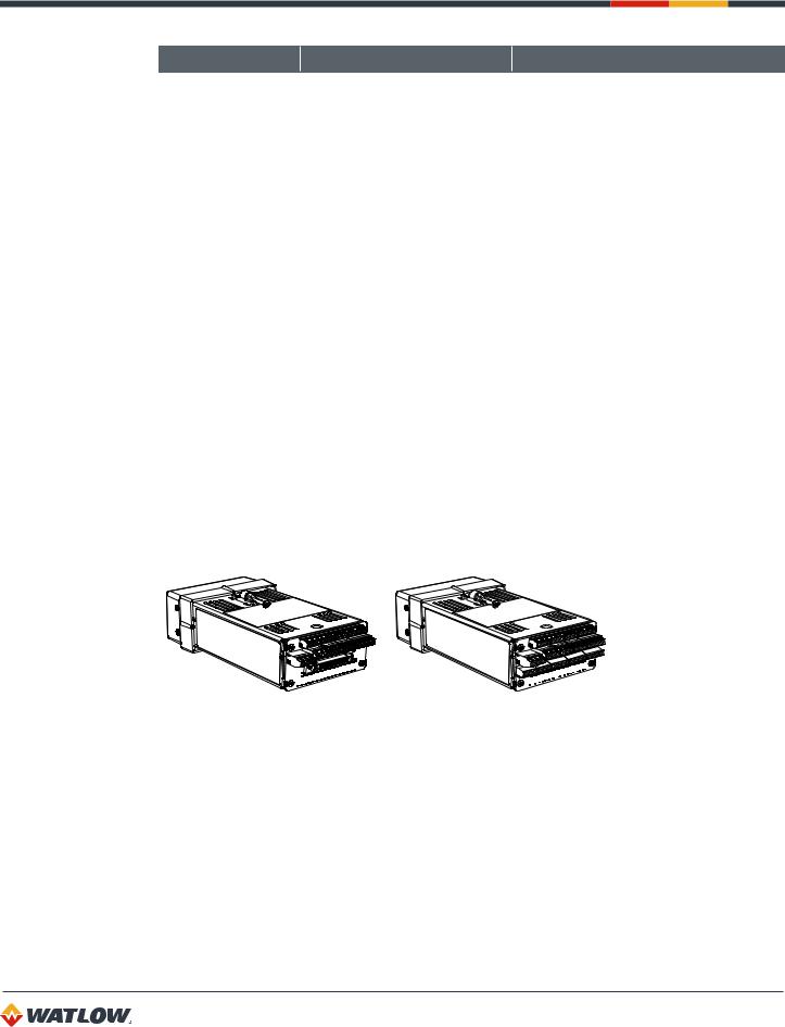
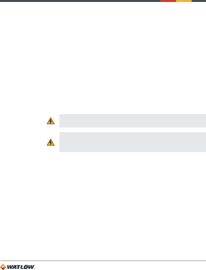
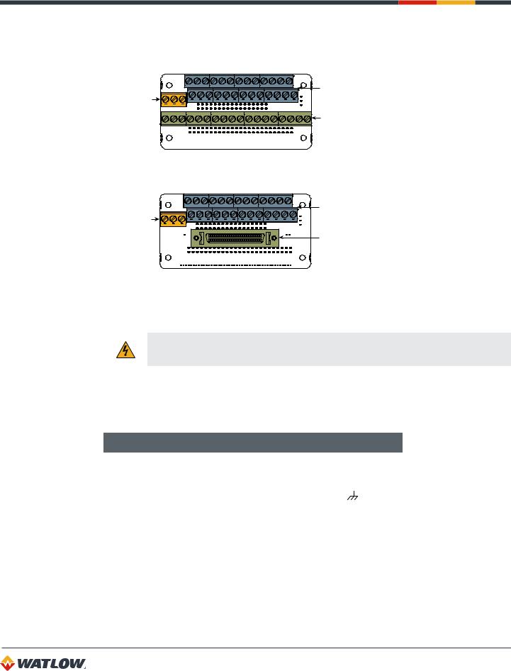
CLS200
The CLS200 is housed in an 1/8-DIN panel mount package. It contains the CPU, RAM with a built-in battery, EPROM, serial communications, digital I/O, analog inputs, the screen and touch keypad.
SCSI Digital I/O Option |
TB18 Digital I/O Option |
Figure 1.1 — CLS200 Rear Views
The CLS200 has the following features:
•Keypad and 2-line, 16-character display.
•Screw terminals for the power and analog inputs and communications.
•Input power is 12 to 24VDC at 1 Amp.
•A 50-pin SCSI cable connects the digital inputs and outputs to the 50-terminal block (TB50). Four-loop and eight-loop models are available with an 18-terminal block (TB18) in place of the SCSI connector, as shown in Figure 1.2.
16
CLS200 Series User’s Guide
Chapter 1: System Overview
The firmware resides in an EPROM. See Replacing the EPROM on page 150 for information on removing and replacing the EPROM.
The operating parameters are stored in battery-backed RAM. If there is a power loss the operating parameters are unchanged. The battery has a ten-year shelf life, and it is not used when the unit is on.
The microprocessor performs all calculations for input signal linearization, PID control, alarms and communications.
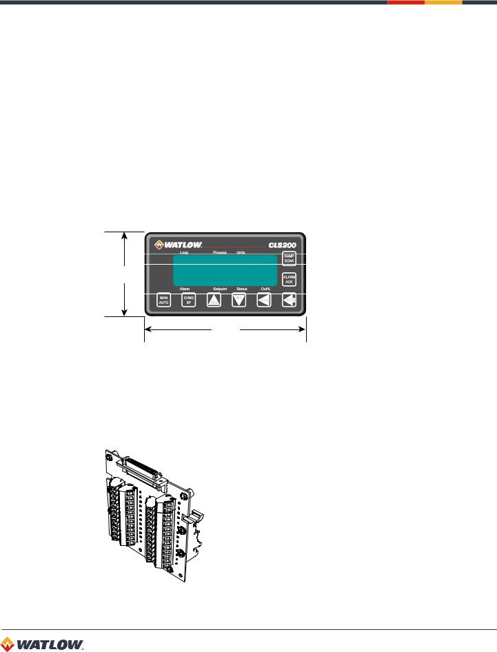
Front Panel Description
The display and touch keypad provide an intelligent way to operate the controller. The display has 16 alphanumeric or graphic characters per line. The 8-key keypad allows you to change the operating parameters, controller functions, and displays.
The information-packed displays show process variables, setpoints, and output levels for each loop. A bar graph display, single loop display, scanning display and an alarm display offer a real-time view of process conditions. Two access levels allow operator changes and supervisor changes.
1.98 in.
(50 mm)
3.80 in.
(96 mm)
Figure 1.2 — CLS200 Front Panel
TB50
The TB50 is an optional screw-terminal interface for control wiring which allows you to connect relays, encoders and discrete I/O devices to the CLS200. The screw terminal blocks accept wires as large as 18 AWG (0.75 mm2). A 50-pin SCSI cable connects the TB50 to the CLS200.
Figure 1.3 — TB50
17
CLS200 Series User’s Guide
Chapter 1: System Overview
CLS200 Cabling
Watlow offers optional cables to support installing your CLS200. A 50-pin SCSI cable connects the TB50 to the CLS200.
The optional cable used to connect the CLS200 to a computer using EIA/TIA-232 communications has a DB9 connector for the computer and bare wires for connecting to the CLS200.
Safety
Watlow has made every effort to ensure the reliability and safety of this product. In addition, we have provided recommendations that will allow you to safely install and maintain this controller.
External Safety Devices
The CLS200 controller may fail full-on (100% output power) or full-off (0% output power), or may remain full-on if an undetected sensor failure occurs. For more information about failed sensor alarms, see Failed Sensor Alarms on page 59.
Design your system to be safe even if the controller sends a 0% or 100% output power signal at any time. Install independent, external safety devices that will shut down the system if a failure occurs.
Typically, a shutdown device consists of an agency approved high/low process limit controller that operates a shutdown device such as a mechanical contactor. The limit controller monitors for a hazardous condition such as an undertemperature or over-temperature fault. If a hazardous condition is detected, the limit controller sends a signal to open the contactor.
The safety shutdown device (limit controller and contactor) must be independent from the process control equipment.
WARNING! The controller may fail in a 0% or 100% power output state. To prevent death, personal injury, equipment damage or property damage, install external safety shutdown devices. If death or injury may occur, you must install approved safety shutdown devices that operate independently from the process control equipment.
With proper approval and installation, thermal fuses may be used in some processes.
Power-Fail Protection
In the occurrence of a sudden loss of power, this controller can be programmed to reset the control outputs to off (this is the default). Typically, when power is re-started, the controller restarts to data stored in memory. If you have programmed the controller to restart with control outputs on, the memory-based restart might create an unsafe process condition for some installations. Therefore, you should only set the restart with outputs on if you are certain your system will safely restart. (See
Process Power Digital Input on page 71.)
When using a computer or host device, you can program the software to automatically reload desired operating constants or process values on power-up. Keep in mind that these convenience features do not eliminate the need for independent safety devices.
Contact Watlow if you have any questions about system safety or system operation.
18
Chapter 2: Installation
This chapter describes how to install the CLS200 series controller and its peripherals. Installation of the controller involves the following procedures:
•Determining the best location for the controller
•Mounting the controller and TB50
•Power connection
•Input wiring
•Communications wiring (EIA/TIA-232 or EIA/TIA-485)
•Output wiring
WARNING! Risk of electric shock. Shut off power to your entire process before you begin installation of the controller.
WARNING! The controller may fail in a 0% or 100% power output state. To prevent death, personal injury, equipment damage or property damage, install external safety shutdown devices. If failure may cause death or injury, you must install approved safety shutdown devices that operate independently from the process control equipment.
Typical Installation
Figure 2.1 shows typical installations of the controller with the TB50 and the TB18 terminal blocks. The type of terminal block you use greatly impacts the layout and wiring of your installation site. (See
Figures 2.2 to 2.11.)
We recommend that you read this entire chapter first before beginning the installation procedure. This will help you to carefully plan and assess the installation.
19
CLS200 Series User’s Guide
Chapter 2: Installation
CLS200 with SCSI Digital I/O |
TB50 Accessory Board |
|
|
Sensor Inputs |
SCSI Cable |
SCSI Connector
TB50 allows connection to...
35 Outputs for Control & Alarms
CLS200 with TB18 Digital I/O 8 Digital Inputs 1 Pulse Input
Sensor Inputs
TB18 allows connection to...
11 Outputs for Control & Alarms
2 Digital Inputs
1 Pulse Input
Figure 2.1 — CLS200 System Components
Mounting Controller Components
Install the controller in a location free from excessive heat (below 50ºC [122°F]), dust, and unauthorized handling. Electromagnetic and radio frequency interference can induce noise on sensor wiring. Select locations for the CLS200 and TB50 such that wiring can be routed clear of sources of interference such as high voltage wires, power switching devices and motors.
NOTE! For indoor use only.
WARNING! To reduce the risk of fire or electric shock, install the CLS200 in a controlled environment, relatively free of contaminants.
Recommended Tools
Use any of the following tools to cut a hole of the appropriate size in the panel.
•Jigsaw and metal file, for stainless steel and heavyweight panel doors.
•1/8-DIN rectangular punch for most panel materials and thicknesses.
•Nibbler and metal file, for aluminum and lightweight panel doors.
20
CLS200 Series User’s Guide
Chapter 2: Installation
You will also need these tools:
•Phillips head screwdriver
•1/8 in. (3 mm) flathead screwdriver for wiring
•Multimeter
Mounting the Controller
Mount the controller before you mount the terminal block or do any wiring. The controller’s placement affects placement and wiring considerations for the other components of your system.
Ensure there is enough clearance for mounting brackets, terminal blocks, and cable and wire connections.
2.44 in.
(62 mm)
1.98 in.
(50 mm)
1.00 in.
(25 mm) 8.00 in.
(203 mm)
Figure 2.2 —Clearance with TB18 Option
2.44 in.
(62 mm)
1.98 in.
(50 mm)
1.00 in.
(25 mm) 10.00 in.
(254 mm)
Figure 2.3 —Clearance with Standard SCSI Cable
21

CLS200 Series User’s Guide
Chapter 2: Installation
2.44 in.
(62 mm)
1.98 in.
(50 mm)
1.00 in.
(25 mm) 9.00 in.
(229 mm)
Figure 2.3a — Clearance with Right-Angle SCSI Cable
4.02 in.
(102 mm)
Figure 2.4 —Mounting Bracket Clearance
1.80 ± 0.020 in.
(45.7 ± 0.5 mm)
3.63 ± 0.020 in.
(92.2 ± 0.5 mm)
Figure 2.5 —Panel Thickness and Cutout Size
22
CLS200 Series User’s Guide
Chapter 2: Installation
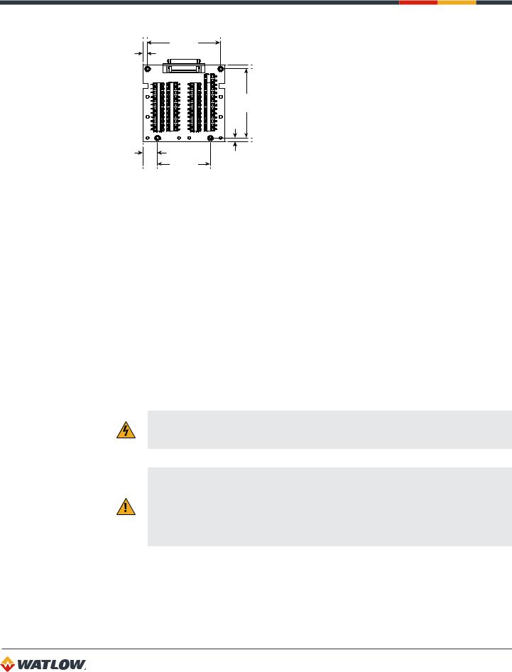
We recommend you mount the controller in a panel not more than 0.2 in. (5 mm) thick.
1.Choose a panel location free from excessive heat (below 50°C [122°F]), dust, and unauthorized handling. (Make sure there is adequate clearance for the mounting hardware, terminal blocks, and cables. The controller extends 7.00 in. (178 mm) behind the panel. Allow adequate room for wiring and cables beyond the connectors.)
2.Temporarily cover slots in the metal housing so that dirt, metal filings, and pieces of wire do not enter the housing and lodge in the electronics.
3.Cut a hole in the panel 1.80 in. (46 mm) by 3.63 in. (92 mm) as shown above. (Use caution; the dimensions given here have 0.02 in. (0.5 mm) tolerances.
4.Remove the brackets and collar from the controller, if they are already in place.
5.Slide the controller into the panel cutout.
6.Slide the mounting collar over the back of the controller, making sure the mounting screw indentations face toward the back of the controller.
7.Loosen the mounting bracket screws enough to allow for the mounting collar and panel thickness. Place each mounting bracket into the mounting slots (head of the screw facing the back of the controller). Push each bracket backward then to the side to secure it to the controller’s case.
8.Make sure the controller is seated properly. Tighten the installation screws firmly against the collar to secure the unit. Ensure that the end of the mounting screws fit into the indentations on the mounting collar.
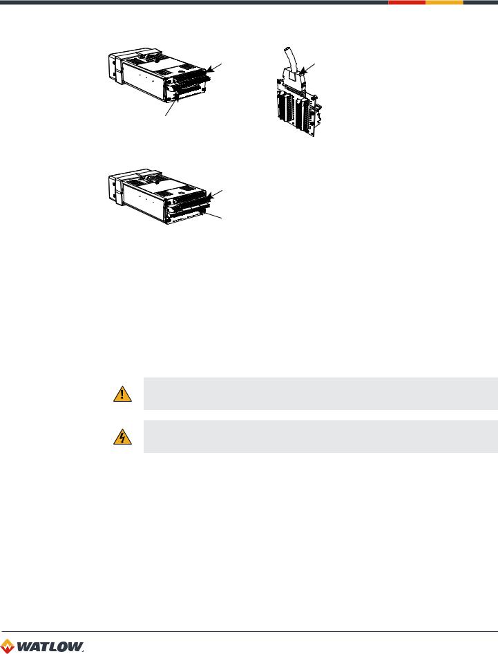
Mounting the TB50
There are two ways you can mount the TB50: use the pre-installed DIN rail mounting brackets or use the plastic standoffs. Follow the corresponding procedure to mount the board.
DIN Rail Mount
Standoffs
Figure 2.6 — Mounting the TB50
23
CLS200 Series User’s Guide
Chapter 2: Installation
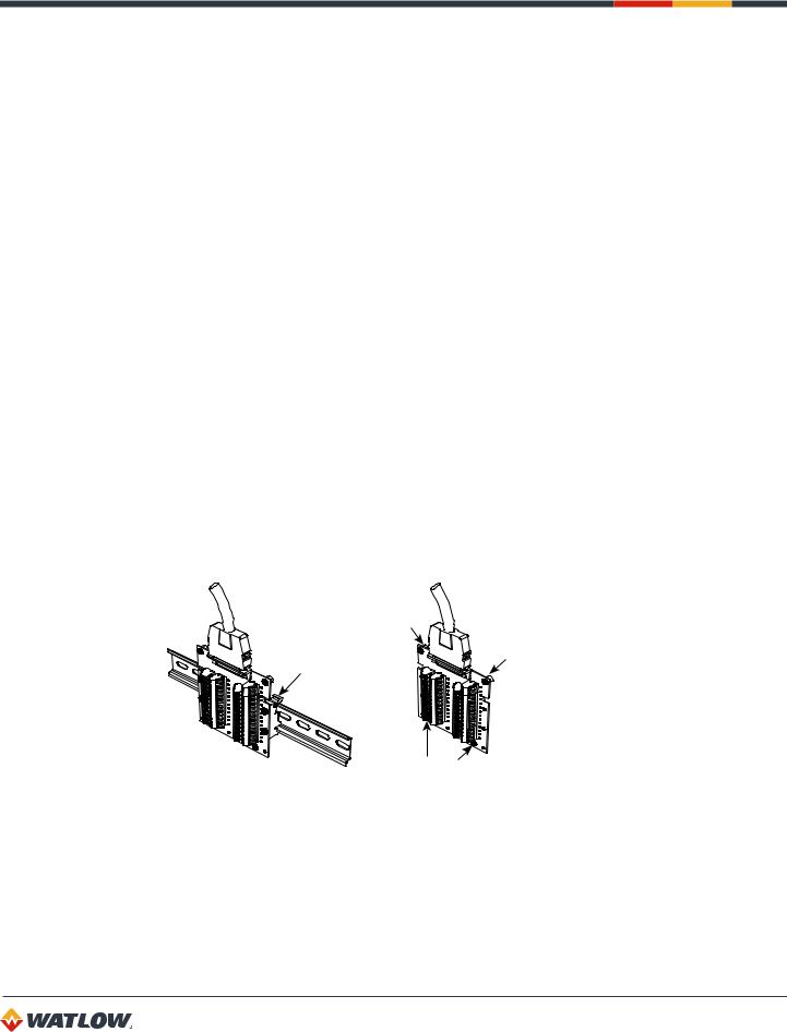
DIN Rail Mounting
Snap the TB50 on to the DIN rail by placing the hook side on the rail first, then pushing the snap latch side in place. (See Figure 2.7.)
Figure 2.7 — TB50 Mounted on a DIN Rail (Front)
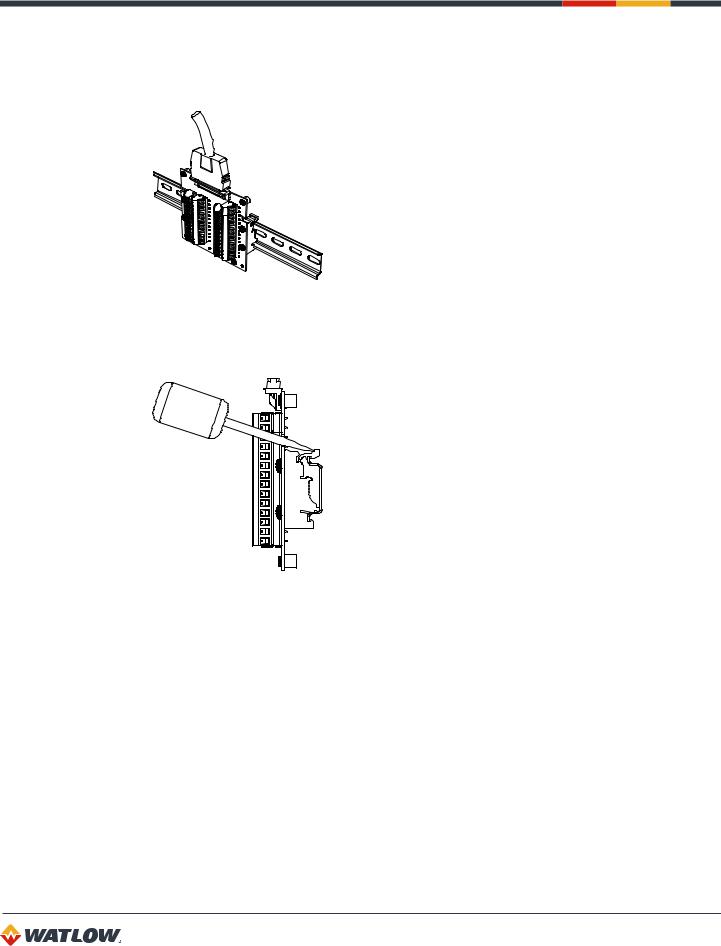
To remove the TB50 from the rail, use a flathead screwdriver to unsnap the bracket from the rail. (See Figure 2.8.)
Figure 2.8 — TB50 Mounted on DIN Rail (Side)
Mounting with Standoffs
1.Remove the DIN rail mounting brackets from the TB50.
2.Select a location with enough clearance to remove the TB50, its SCSI cable and the controller itself.
3.Mark the four mounting holes.
4.Drill and tap four mounting holes for #6 (3.5 mm) screws or bolts.
5.Mount the TB50 with four screws.
There are four smaller holes on the terminal board. Use these holes to secure wiring to the terminal block with tie wraps.
24
CLS200 Series User’s Guide
Chapter 2: Installation
|
3.6 in. |
|
|
0.2 in. |
(91 mm) |
|
|
(5 mm) |
|
|
|
|
|
3.6 in. |
|
|
|
(91 mm) |
|
0.7 in. |
|
0.2 in. |
|
(18 mm) |
2.6 in. |
||
(5 mm) |
|||
|
(66 mm) |
||
|
|
Figure 2.9 — Mounting a TB50 with Standoffs
Mounting the Power Supply
Refer to the power supply manufacturer’s instructions for mounting information. Choose a Class 2 power supply that supplies an isolated regulated 12 to 24VDC at 1A.
Mounting Environment
Leave enough clearance around the power supply so that it can be removed.
System Wiring
Successful installation and operation of the control system can depend on placement of the components and on selection of the proper cables, sensors, and peripheral components.
Routing and shielding of sensor wires and proper grounding of components can insure a robust control system. This section includes wiring recommendations, instructions for proper grounding and noise suppression, and considerations for avoiding ground loops.
WARNING! To reduce the risk of electrical shock, fire, and equipment damage, follow all local and national electrical codes. Correct wire sizes, fuses and thermal breakers are essential for safe operation of this equipment.
CAUTION! Do not wire bundles of low-voltage signal and control circuits next to bundles of high voltage ac wiring. High voltage may be inductively coupled onto the low-voltage circuits, which may damage the controller or induce noise and cause poor control.
Physically separate high-voltage circuits from low-voltage circuits and from CLS200 hardware. If possible, install high-voltage ac power circuits in a separate panel.
25

CLS200 Series User’s Guide
Chapter 2: Installation
Wiring Recommendations
Follow these guidelines for selecting wires and cables:
•Use stranded wire. (Solid wire can be used for fixed service; it makes intermittent connections when you move it for maintenance.)
•Use 20 AWG (0.5 mm2) thermocouple extension wire. Larger or smaller sizes may be difficult to install, may break easily, or may cause intermittent connections.
•Use shielded wire. The electrical shield protects the signals and the CLS200 from electrical noise. Connect one end of the input and output wiring shield to earth ground.
•Use copper wire for all connections other than thermocouple sensor inputs.
Table 2.1 — Cable Recommendations
FUNCTION |
MFR. P/N |
NO. OF WIRES |
AWG |
MM2 |
MAXIMUM LENGTH |
|
|
|
|
|
|
|
|
Analog Inputs |
Belden 9154 |
2 |
20 |
0.5 |
|
|
Belden 8451 |
2 |
22 |
0.5 |
|
||
|
|
|||||
|
|
|
|
|
|
|
RTD Inputs |
Belden 8772 |
3 |
20 |
0.5 |
|
|
Belden 9770 |
3 |
22 |
0.5 |
|
||
|
|
|||||
|
|
|
|
|
|
|
Thermocouple |
T/C Ext. Wire |
2 |
20 |
0.5 |
|
|
Inputs |
|
|||||
|
|
|
|
|
||
|
|
|
|
|
|
|
Control Outputs |
Belden 9539 |
9 |
24 |
0.2 |
|
|
Belden 9542 |
20 |
24 |
0.2 |
|
||
and Digital I/O |
|
|||||
Ribbon Cable |
50 |
22 to 14 |
0.5 to 2.5 |
|
||
|
|
|||||
|
|
|
|
|
|
|
Analog Outputs |
Belden 9154 |
2 |
20 |
0.5 |
|
|
Belden 8451 |
2 |
22 |
0.5 |
|
||
|
|
|||||
|
|
|
|
|
|
|
|
Belden 9729 |
4 |
24 |
0.2 |
4,000 ft. (1,219 m) |
|
Computer |
Belden 9730 |
6 |
24 |
0.2 |
|
|
Communication: |
Belden 9842 |
4 |
24 |
0.2 |
4,000 ft. (1,219 m) |
|
EIA/TIA-232, 422 |
||||||
Belden 9843 |
6 |
24 |
0.2 |
|
||
or 485, or 20mA |
|
|||||
|
Belden 9184 |
4 |
22 |
0.5 |
6,000 ft. (1,829 m) |
|
|
|
|
|
|
|
Noise Suppression
The CLS200’s outputs are typically used to drive solid state relays. These relays may in turn operate more inductive types of loads such as electromechanical relays, alarm horns and motor starters. Such devices may generate electromagnetic interference (EMI or noise). If the controller is placed close to sources of EMI, it may not function correctly. Below are some tips on how to recognize and avoid problems with EMI.
For earth ground wire, use a large gauge and keep the length as short as possible. Additional shielding may be achieved by connecting a chassis ground strap from the panel to CLS200 case.
26

CLS200 Series User’s Guide
Chapter 2: Installation
Symptoms of RFI/EMI
If your controller displays the following symptoms, suspect EMI:
•The controller’s display blanks out and then reenergizes as if power had been turned off for a moment.
•The process variable does not display correctly.
Noise may also damage the digital output circuit—so digital outputs will not turn on. If the digital output circuit is damaged, return the controller to Watlow for repair.
Avoiding RFI/EMI
To avoid or eliminate most RFI/EMI noise problems:
•Connect the CLS200 case to earth ground. The CLS200 system includes noise suppression circuitry. This circuitry requires proper grounding.
•Separate the 120 or 240VAC power leads from the low-level input and output leads connected to the CLS200 series controller. Do not run the digital I/O or control output leads in bundles with ac wires.
•Where possible, use solid-state relays (SSRs) instead of electromechanical relays. If you must use electromechanical relays, try to avoid mounting them in the same panel as the CLS200 series equipment.
•If you must use electromechanical relays and you must place them in a panel with CLS200 series equipment, use a 0.01 microfarad capacitor rated at 1000VAC (or higher) in series with a 47Ω, 0.5 watt resistor across the normally-open contacts of the relay load. This is known as a snubber network and can reduce the amount of electrical noise.
•You can use other voltage suppression devices, but they are not usually required. For instance, you can place a metal oxide varistor (MOV) rated at 130VAC for 120VAC control circuits across the load, which limits the peak ac voltage to about 180VAC. You can also place a transorb (back-to-back zener diodes) across the digital output, which limits the digital output voltage.
Additional Recommendations for a Noise Immune System
It is strongly recommended that you:
•Isolate outputs through solid-state relays, where possible.
•Isolate RTDs or “bridge” type inputs from ground.
•Isolate digital inputs from ground through solid state relays. If this is not possible, then make sure the digital input is the only connection to earth ground other than the chassis ground.
•If you are using EIA/TIA-232 from a non-isolated host, either (1) do not connect any other power common point to earth ground, or (2) use an optical isolator in the communications line.
27

CLS200 Series User’s Guide
Chapter 2: Installation
Ground Loops
Ground loops occur when current passes from the process through the controller to ground. This can cause instrument errors or malfunctions.
A ground loop may follow one of these paths, among others:
•From one sensor to another.
•From a sensor to the communications port.
•From a sensor to the dc power supply.
The best way to avoid ground loops is to minimize unnecessary connections to ground. Do not connect any of the following terminals to each other or to earth ground:
•Power supply dc common
•TB1, terminals 5, 6, 11, 12 (analog common)
•TB1, terminal 17 (reference voltage common)
•TB1, terminals 23, 24 (communications common)
•TB2, terminal 2 (dc power common)
Special Precautions for the Sixteen-Loop Models
Sixteen-loop models have single-ended inputs. All the negative sensor leads are tied to the analog common. That means there is no sensor-to-sensor isolation. Proper grounding is critical for this unit. Take these additional precautions with a sixteen-loop controller:
•Use all ungrounded or all well-grounded thermocouples, not a mix.
•If using a mixture of thermocouples or low-voltage inputs (<500mV) and current inputs, connect the negative leads of the current transmitters to terminal 17 (Ref Com) on TB1.
•If using voltage transmitters, use only sourcing models or configuration. Sinking configurations will not work.
•Isolate the controller’s communication port (if used) by using an optically isolated 232-to-485 converter.
Personal Computers and Ground Loops
Many PC communications ports connect the communications common to chassis ground. When such a PC is connected to the controller, this can provide a path to ground for current from the process that can enter the controller through a sensor (such as a thermocouple). This creates a ground loop that can affect communications and other controller functions. To eliminate a ground loop, either use an optically isolated communications adapter or take measures to ensure that sensors and all other connections to the controller are isolated and not conducting current into the unit.
28
CLS200 Series User’s Guide
Chapter 2: Installation
Power Connections
This section covers making the power connections to the CLS200 and connecting the TB50.
|
TB1 |
|
Sensor Inputs |
TB2 |
Serial Communication |
|
|
Power Input |
|
TB18 |
Digital Inputs |
Digital Outputs |
Pulse Input |
Figure 2.10 — CLS200 Series Controller with TB18
TB2 |
Power Input |
Figure 2.11 — CLS200 Series Controller with TB50
TB1
Sensor Inputs
Serial Communication
SCSI to TB50
Digital Inputs
Digital Outputs
Pulse Input
Wiring the Power Supply
WARNING! Use a power supply with a Class 2 rating only. UL® approval requires a Class 2 power supply.
Connect power to the controller before any other connections, This allows you to ensure that the controller is working before any time is taken installing inputs and outputs.
Table 2.2 — Power Connections
FUNCTION |
POWER SUPPLY |
CLS200 TB2 |
|
|
|
DC Power (Controller) |
+12 to 24VDC |
+ |
|
|
|
DC Common |
12 to 24VDC Common |
– |
|
|
|
Earth Ground |
Ground |
|
|
|
|
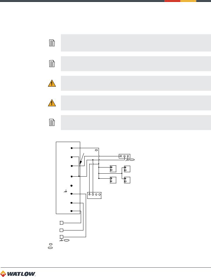
1.Connect the dc common terminal on the power supply to the dc common (-) terminal on CLS200 TB2.
2.Connect the positive terminal on the power supply to the dc positive (+) terminal on CLS200 TB2.
3.If using an isolated dc output or another power supply to power the loads, connect the dc common of the supply powering the loads to the dc common of the supply powering the controller.
29
CLS200 Series User’s Guide
Chapter 2: Installation
4.Use the ground connector on TB2 for chassis ground. This terminal is connected to the CLS200 chassis and must be connected to earth ground.
5.Connect 120/240VAC power to the power supply.
NOTE! Connect the dc common of the power supply used for loads to the dc common of the supply powering the controller. If the supplies are not referenced to one another, the controller’s outputs will not be able to switch the loads.
NOTE! When making screw terminal connections, tighten to 4.5 to 5.4 inch-pound (0.5 to 0.6 Nm).
CAUTION! Without proper grounding, the CLS200 may not operate properly or may be damaged.
CAUTION! To prevent damage from incorrect connections, do not turn on the ac power before testing the connections as explained in Testing Your System on page 31.
NOTE! Do not connect the controller’s dc common (COM) to earth ground. Doing so will defeat the noise protection circuitry, making measurements less stable.
Power Supply
+V1 (5V) |
|
|
C G |
|
|
|
|
||
|
Add jumper * |
V O N |
||
0 (5V COM) |
+ M D CLS200 |
|||
|
|
|||
+V2 (+15V) |
|
|
** |
|
|
SSR |
SSR |
||
COM (15V COM) |
|
SSR |
SSR |
|
|
|
|||
-V2 (-15V) |
|
|
|
|
(Ground) |
|
2 3 4 Serial DAC |
|
|
ACL (AC Line) |
1 |
|
||
+ |
C |
|
||
|
5 |
O |
|
|
ACN (AC Neutral) |
|
M |
|
|
|
|
|
||
N white
120/240
VAC H black
Supply G green
**
* If using 5VDC for outputs, jumper 5V common to 15V common. ** Connect terminals to ac panel ground.
Figure 2.12 —Power Connections
30
Loading...