


 Loading...
Series 965
User's Manual

 96
96
1/16 DIN
Microprocessor-Based
Auto-tuning Control
WatlowControls
TOTAL
CUSTOMER SATISFACTION
3YearWarranty
ISO 9001
Registered Company
Winona, Minnesota USA
Watlow Controls, 1241 Bundy Blvd., P.O. Box 5580, Winona, MN 55987-5580, Phone: 507/454-5300, Fax: 507/452-4507
0600-0003-0000 Rev. C |
$10.00 |
July 1998 |
Made in the U.S.A. |
Supersedes: 0600-0003-0000 Rev. B |
Printed on Recycled Paper |
|

About This Manual
NOTE:
Details of a "Note" appear here, in the narrow box on the outside of each page.
How to Use this Manual
We have designed this user's manual to be a helpful guide to your new Series 965. The headlines in the upper right and left corners indicate which tasks are explained on that page.
Notes and Safety Information
We use notes, cautions and warnings throughout this book to draw your attention to important information.
Notes are printed in bold in the margin to alert you to an important detail.
|
ç |
ç |
A Caution symbol (an exclamation point in a triangle) appears with information that is |
important to protect equipment and performance. Read and follow all cautions that apply |
|
|
to your application. |
CAUTION: Details of a "Cau-
tion" appear here, in the narrow box on the outside of each page.
Ó
A Warning symbol (a lightning bolt in a diamond) appears with information that is important to protect people and equipment from damage. Pay very close attention to all warnings that apply to your application.
Ó
WARNING: Details of a "Warn-
ing" appear here, in the narrow box on the outside of each page.
Technical Assistance
If you encounter a problem with your Watlow controller, review all of your configuration information for each step of the setup, to verify that your selections are consistent with your applications.
If the problem persists after checking all the steps, call for technical assistance: Watlow Controls at (507) 454-5300, between 7:00 a.m. and 5:30 p.m. Central Standard Time. Ask for an applications engineer. When you call, have the following information ready:
•the controller's model number ( the 12-digit number is printed on the top of the stickers on each side of the controller's case and on the top or right side of the circuit board);
•this user's manual;
•all configuration information;
•the Diagnostics Menu readings.
Warranty and Returns
For information about the warranty covering the Series 965, see page 37.
Comments and Suggestions
We welcome your comments and opinions about this user's manual and the Series 965. Send them to the Technical Editor, Watlow Controls, 1241 Bundy Blvd., P.O. Box 5580, Winona,MN55987-5580.Orcall(507)454-5300.Orfaxthemto(507)452-4507.(1459).
2 |
WATLOW Series 965 User's Manual |
How to Use the Manual |

Page |
Item |
Chapter 1
4 Starting Out With The Watlow Series 965
4 General Description
Chapter 2
5 Install And Wire The Series 965
5 Panel Cutout
5 Dimensions
5 Installation Procedure
7Wiring the Series 965
8Sensor Installation Guidelines
8 Input Wiring
10Output 1 Wiring
11Alarm Wiring
12System Wiring Example
Chapter 3
13 How To Use The Keys And Displays
13 Keys, Displays & LEDs
Chapter 4
14How To Set Up The Series 965
14Setting the Input Type DIP Switch
15Entering Setup Menu
16Setup Parameters
18Setup Menu Table
19Operation Parameters
20Operation Menu Table
Chapter 5
21How To Tune And Operate
21Auto-tuning
22Manual Tuning
23Manual and Automatic Operation
24Using Alarms
25Error Code Messages
Appendix 1
27 Noise Sources
27Decreasing Noise Sensitivity
28Eliminating Noise
Appendix 2
29Entering the Calibration Menu
30Restoring Factory Calibration
30Calibration Menu
Contents
31 Calibration Procedures
34 Glossary
36Index
37Warranty and Returns
38Specifications
39Model Number Information
40Declaration of Conformity
41Quick Reference
Figures & Tables |
|
|
|
Page |
Figure |
Item |
|
4 |
Series 965 Input & Output Overview |
1 |
|
5 |
Multiple Panel Cutout Dimensions |
2 |
|
5 |
Series 965 Dimensions |
3 |
|
6 |
Mounting, Case Side View & Collar |
4 |
|
6 |
Case, Rear View & NEMA 4X Seal Example |
5 |
|
7 |
High Voltage Power Wiring |
6 |
|
7 |
Low Voltage Power Wiring |
7 |
|
8 |
Thermocouple Sensor Input Wiring |
8 |
|
8 |
0-5VÎ (dc) Process Sensor Input Wiring |
9 |
|
9 |
2- or 3-wire RTD Sensor Input Wiring |
10 |
|
9 |
4-20mA Process Sensor Input Wiring |
11 |
|
10 |
Switched DC Output Wiring |
12 |
|
10 |
5A Mechanical Relay Wiring |
13 |
|
10 |
4-20mA Process Wiring |
14 |
|
10 |
0.5A Solid-state Relay w/o Suppression Wiring 15 |
||
11 |
Switched DC Output Wiring |
16 |
|
11 |
5A Mechanical Relay Wiring |
17 |
|
11 |
0.5A Solid-state Relay w/o Suppression Wiring 18 |
||
12 |
System Wiring Example |
19 |
|
13 |
Series 965 Keys and Displays |
20 |
|
14 |
DIP Switch Location & Orientation |
21 |
|
15 |
Entering the Setup Menu |
22 |
|
15 |
The Setup Menu |
23 |
|
19 |
The Operation Menu |
24 |
|
21 |
Auto-tuning at a 200°F Set Point |
25 |
|
24 |
Alarm Display Examples |
26 |
|
29 |
Entering the Calibration Menu |
27 |
|
30 |
Calibration Menu |
28 |
|
|
|
|
Tables |
18 |
Input Ranges 1 |
|
|
18 |
Setup Menu Prompts/Description |
2 |
|
20 |
Operation Menu Prompts/Description |
3 |
|
41 |
Quick Reference Sheet (Perforated) |
|
|
How to Use the Manual |
WATLOW Series 965 User's Manual |
3 |

Starting Out
Chapter 1
Starting Out With The Watlow Series 965,
A Microprocessor-Based Control
Single Input -
Type J, K, T, N or S
Thermocouple,
RTD or Process
Figure 1 -
Series 965 Input and
Output Overview
Dual Control Output-
PID or on/off, User Selectable
Output 1 -
Heat or Cool
Output 2 -
Cool, Alarm
None
Output 1 or 2 |
Auto-tuning |
Percent Power |
for Heat & |
|
Cool PID |
|
Settings |
General Description
Welcome to the Watlow Series 965, a 1/16 DIN microprocessor-based temperature control. The 965 has a single input which accepts type J, K, T, N or S thermocouple, RTD or process input.
With dual output, the primary can be heating or cooling while the secondary can be a control output opposite the primary output (heat or cool), alarm or none. Both outputs can be selected as either PID or on/off. PID settings include proportional band, reset/integral, and rate/derivative. Setting the proportional band to zero makes the Series 965 a simple on/off control with switching differential selectable under the HSC parameter.
Special 965 features include the NEMA 4X rating, dual four digit displays in either red or green, optional low volt power supply, auto-tuning for both heat and cool outputs, ramp to set point for gradual warm-up of your thermal system, and automatic/manual capability with bumpless transfer.
Operator-friendly features include automatic LED indicators to aid in monitoring and setup, as well as a calibration offset at the front panel. The Watlow Series 965 automatically stores all information in a non-volatile memory.
4 WATLOW Series 965 User's Manual |
Getting Started, Chapter 1 |
Chapter 2 |
|
|
|
|
|
|
|
|
|
|
Installation |
||
Install and Wire the Series 965 |
|
|
|
|
|
|
|||||||
|
|
|
|
1.77" to 1.79" |
|
|
|
|
|
|
|||
|
|
|
|
(44.96mm to 45.47mm) |
|
|
|
|
|
|
|
|
|
|
|
|
|
|
|
|
|
|
|
|
|||
|
|
|
|
|
|
|
|
|
|
|
|
||
|
|
|
|
|
|
|
|
|
|
|
|
|
|
|
|
|
|
Panel Cutout |
|
|
|
|
|
|
|||
|
|
|
|
|
|
|
|
|
|
||||
|
|
NOTE: |
|
Your Panel |
|
|
|
|
|
|
|||
|
|
|
1.77" to 1.79" |
|
|||||||||
|
|
|
Thickness |
|
|||||||||
|
|
Measurements |
|
|
|||||||||
|
|
|
|
|
|
|
|
|
(44.96mm |
|
|||
|
|
between panel |
|
0.06" to 0.38" |
|
to 45.47mm) |
|
||||||
|
|
cutouts are the |
|
(1.5 to 9.7 mm) |
|
|
|
|
|
|
|||
|
|
minimum |
|
|
|
|
|
|
|
|
|
|
|
|
|
recommended. |
|
|
|
|
|
|
|
|
|
|
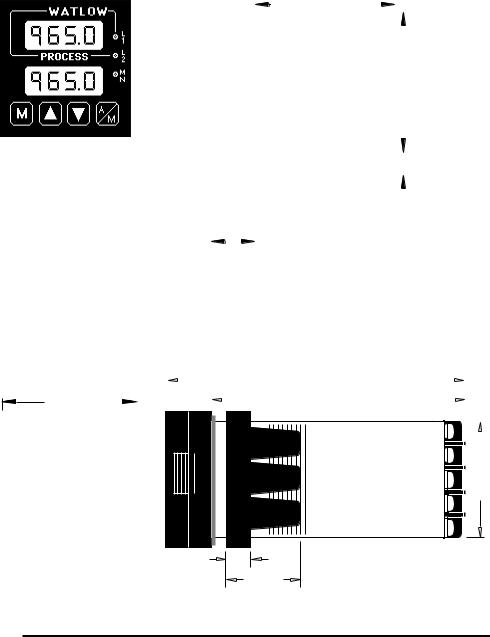
Figure 2 - |
|
|
|
|
|
|
|
|
|
|
||||
|
|
|
|
|
|
|
|
|
|
|
0.38" |
|
Series 965 |
|
|
|
|
|
|
|
|
|
|
||||
|
|
|
|
|
|
|
|
|
|
|
(9.65mm) |
Multiple Panel |
|
|
|
|
|
|
|
|
|
|
|
|
Minimum |
Cutout Dimensions |
|
|
|
|
0.85" |
|
|
|
|
|
|
|
|
|
|
|
|
|
|
|
|
|
|
|
|
|
|
|
|
|
|
|
(20mm) |
|
|
|
|
|
|
|
|||
|
|
|
|
|
|
|
|
|
|
|
|
|
|
|
|
|
|
|
|
|
|
|
|
|
|
|
|
|
|
|
|
|
|
|
|
|
|
|
|
|
|
|
|
|
|
|
4.7" |
|
|
|
|
|
|
|
|
|
|
Figure 3 - |
||||||
|
|
|
|
|
|
|
|
|
|
|
|
Series 965 |
||||||||||
|
|
|
|
|
|
|||||||||||||||||
|
|
|
|
|
|
|
|
|
|
|
(119mm) |
|
|
|
|
|
|
|
|
|
Dimensions |
|
2.1" |
|
|
|
|
|
|
|
|
|
|
|
|
4.1" |
|
|
|
|
|
|
|
||
|
|
|
|
|
|
|
|
|
|
|
|
|
|
|
|
|
||||||
(53 mm) |
|
|
|
|
|
|
|
|
|
|
|
|
(104mm) |
|
|
|
|
|||||
|
|
|
|
|
|
|
|
|
|
|
|
|
|
|
|
|
||||||
|
|
|
|
|
|
|
|
|
|
|
|
|
|
|
|
|
|
|
|
|
|
|
|
|
|
|
|
|
|
|
|
|
|
|
|
|
|
|
|
|
|
|
|
|
|
|
|
|
|
|
|
|
|
|
|
|
|
|
|
|
|
|
|
|
|
|
|
|
|
|
|
|
|
|
|
|
|
|
|
|
|
|
|
|
|
|
|
|
|
|
|
|
|
|
|
|
|
|
|
|
|
|
|
|
|
|
|
|
|
|
|
|
|
|
|
|
|
|
|
|
|
|
|
|
|
|
|
|
|
|
|
|
|
|
|
|
|
|
1.76" |
|
|
(45mm) |
|
|
NOTE: For rapid |
|
|
mounting, use |
|
|
Greenlee punch |
|
|
#60020 and die |
|
0.40" |
#60021, or hand |
|
hydraulic unit, Kit |
||
(10mm) |
||
#7306. All available |
||
1.21" |
||
(31mm) |
from Grainger. |
Installation Procedure
Follow this procedure to mount the Watlow Series 965 temperature control:
1.Make a panel cutout per the dimensions in Figure 2.
2.Remove the 965 chassis from its case. Holding each side of the bezel, press in firmly on the side grips until the tabs release. Pull the chassis out of the case and set aside for later installation.
3.Make sure the rounded side of the external case gasket is facing the panel surface. Check to see that the gasket is not twisted, and is seated within the case bezel flush with the panel. Place the case in the cutout you just made. Make sure the gasket is between the panel cutout and the case bezel. See Figure 4A.
Install and Wire, Chapter 2 |
WATLOW Series 965 User's Manual 5 |
Installation
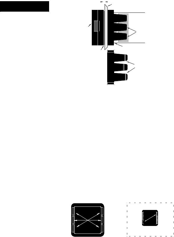
Figure 4 - |
4A |
Mounting, Case Side |
View & Collar Cross
Section
4B
|
|
|
|
|
|
|
0 to 0.019 space |
|
|
|
Panel |
||
|
||||||
(0 to 0.483 mm) |
|
|
|
|
||
|
|
|
|
|
|
|
Ridges |
|
Bezel |
|
Tabs |
|
Mounting Collar |
|
External Gasket |
|
Teeth |
Mounting Collar |
Cross Section |
|
|
(notice the offset teeth |
|
on each tab) |
NOTE:
To guarantee a proper NEMA 4X seal, make sure the gasket between the panel and the rim of the case is not twisted and is seated properly.
PRESS FIRMLY.
Figure 5 -
Case Rear View and
NEMA 4X Seal
Example
4.While pressing the front of the case firmly against the panel, slide the mounting collar over the back of the control. The tabs on the collar must line up with the mounting ridges on the case for secure installation. See Figure 4A again. Slide the collar firmly against the back of the panel getting it as tight as possible. Make sure you cannot move the case within the cutout; if you can you do not have a NEMA 4X seal.
Now let's make sure we have a tight seal. Use your thumb to lock the tabs into place while pressing the case from side to side. Don't be afraid to apply enough pressure to install the control. The tabs on each side of the collar have teeth which latch into the ridges. See Figure 4B. Each tooth is staggered at a different height, so only one of the tabs on each side are ever locked into the ridges at any time.
Looking at Figure 5, you see that the tabs on one side of the collar correspond with those on the opposite side. Make sure that the two corresponding tabs are the only ones locked in the ridges at the same time. If the matching tabs are not holding the case at the same time you will not have a NEMA 4X seal. You can make a visual check, or use your finger nail to pull out on each tab. Only one on each side is engaged, and they must be corresponding as in Figure 5. The space between the bezel and panel must be between 0 and 0.019" (0.48 mm).
Make sure that the two corresponding tabs below are locked in the ridges at the same time.
NEMA 4X Seal Example. |
When removing the mounting collar, we suggest sliding a thin tool such as a putty knife or screwdriver under all three tabs on each side at once and pulling it back off the case.
5.Insert the control chassis into its case and press the bezel to seat it. Make sure the inside gasket is also seated properly and not twisted. The hardware installation is complete. Proceed to the wiring section from here.
6 WATLOW Series 965 User's Manual |
Install and Wire, Chapter 2 |

How to Wire the Series 965
The Series 965 wiring is illustrated by model number option. Check the unit sticker on the control and compare your model number to those shown here and also the model number breakdown in the Appendix of this manual.
All outputs are referenced to a de-energized state. The final wiring figure is a typical system example.
When you apply power without sensor inputs on the terminal strip, the Series 965 displays [----] in the upper display, and a [```0] in the lower display, except for 0-5VÎ (dc) or 4-20mA process input units. Press the A/M key twice, and [ER`7] is displayed for one second. This error indicates an open sensor or A/D error. Remove power to the control and connect the sensor properly, see pages 8 and 9. All wiring and fusing must conform to the National Electric Code and to any locally applicable codes as well.
High Voltage
Model # |
965A - 3 |
|
|
|
0 - 00 |
100 to 240 VÅ (ac), nominal
(85 to 264 actual)
Power Wiring
Ó
WARNING:
To avoid potential electric shock, use National Electric Code (NEC) safety practices when wiring and connecting this unit to a power source and to electrical sensors or peripheral devices.
NOTE:
Taking the unit out of the case is not a normal operating condition and should only be done by a qualified maintenance installation technician. Power to the case should be disconnected before removing or installing the controller into its case.
Figure 6 -
High Voltage
Power Wiring
Low Voltage
Model # |
965A - 3 |
1 - 00 |
|
|
|
|
Figure 7 - |
|||
|
|
|
|
|
|
|
|
|
|
|
|
Ó |
|
|
|
|
|
|
Low Voltage |
||
|
|
12-24V‡ (ac/dc) |
Power Wiring |
|||||||
|
|
|
||||||||
|
|
|
|
|
|
|
|
|
|
Ó |
|
|
|
|
|
|
|
|
|
|
WARNING: |
|
|
|
|
|
|
|
|
|
|
If high voltage is |
|
|
|
|
|
|
|
|
|
|
applied to the low |
|
|
|
|
|
|
|
|
|
|
voltage unit, |
|
|
|
|
|
|
|
|
|
|
irreversible damage |
|
|
|
|
|
|
|
|
|
|
will occur. |
Install and Wire, Chapter 2 |
WATLOW Series 965 User's Manual |
7 |
Input Wiring
Sensor Installation Guidelines
We suggest you mount the sensor at a location in your process or system where it reads an average temperature. Put the sensor as near as possible to the material or space you want to control. Air flow past this sensor should be moderate. The sensor should be thermally insulated from the sensor mounting.
See Chapter 4 for more information on DIP switch location and orientation.
NOTE:
When an external device with a nonisolated circuit common is connected to the 4- 20mA or dc output, you must use an isolated or ungrounded thermocouple.
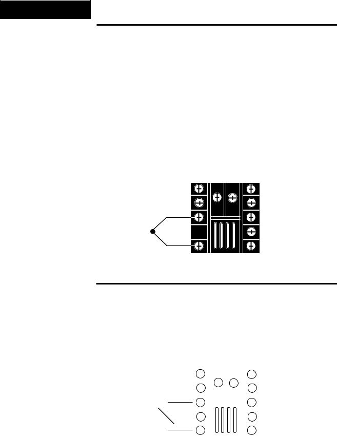
Figure 8 -
Thermocouple
Sensor Input Wiring
Thermocouple Input
Extension wire for thermocouples must be of the same alloy as the thermocouple itself to limit errors.
DIP Switch
Orientation
+ 3
T/C
- 5
ç
CAUTION:
Process input does not have sensor break protection. Outputs can remain full on.
0-5VÎ (dc) Process Input
ç
DIP Switch
Orientation
Figure 9 - |
+ |
3 |
|
||||||
0-5V |
Î |
|
|
|
|
|
|
|
|
(dc) Process |
|
|
|
|
|
|
|
|
|
Sensor Input Wiring |
V d c |
|
|
|
|
|
|||
|
|
|
|||||||
|
|
|
|
||||||
|
|
|
|
|
|
|
|
|
|
|
|
|
|
|
- |
5 |
|
||
|
|
|
|
|
|
|
|
|
|
Input impedance: 10KΩ
8 |
WATLOW Series 965 User's Manual |
Install and Wire, Chapter 2 |

RTD, 2- or 3-wire
There could be a + 2°F input error for every 1Ω of lead length resistance when using a 2-wire RTD. That resistance, when added to the RTD element resistance, will result in erroneous input to the instrument. To overcome this problem, use a 3-wire RTD sensor, which compensates for lead length resistance. When extension wire is used for a 3-wire RTD, all wires must have the same electrical resistance (i.e. same gauge, copper stranded, same length).
DIP Switch
Orientation
S1 |
2 |
S1 |
2 |
|
S2 |
3 |
S2 |
3 |
|
3-wire RTD |
|
2-wire RTD |
|
|
|
Jumper |
|
||
|
|
|
||
|
|
Terminals |
|
|
S3 |
5 |
3 and 5. |
|
|
S3 |
5 |
|||
|
|
4 - 20mA Process Input
ç
DIP Switch
Orientation
- 2
I d c
+ 5
Input impedance: 5Ω
Input Wiring
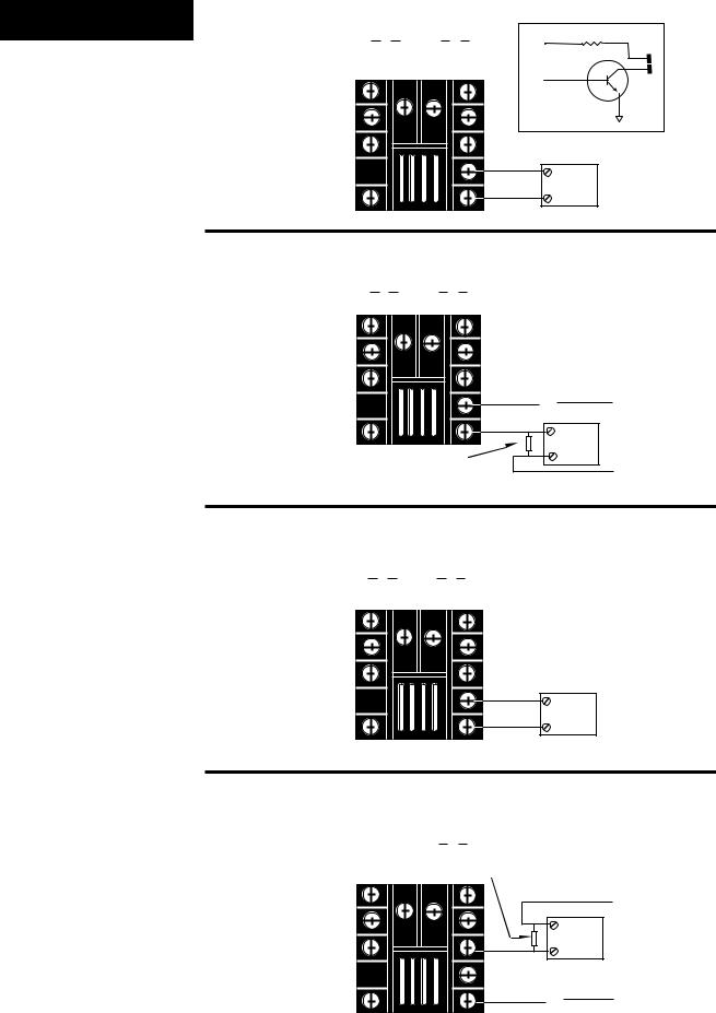
Figure 10 -
2- or 3-wire RTD Sensor Input Wiring
ç
CAUTION:
Process input does not have sensor break protection. Outputs can remain full on.
Figure 11 -
4-20mA Process
Sensor Input Wiring
Install and Wire, Chapter 2 |
WATLOW Series 965 User's Manual |
9 |
Output 1 Wiring |
Switched DC Output |
|
|
|
Model # 965A - 3 C |
- 00 |
V+ |
|
|
|
|
|
unregulated |
|
|
|
|
|
9 |
Figure 12 - |
|
|
V— |
10 |
|
|
|
||
Switched dc Output |
|
|
|
|
Wiring |
|
|
|
|
|
|
|
Internal Circuitry |
|
NOTE: |
|
9 |
+ |
|
When an external |
|
|
|
External |
device with a non- |
|
10 |
- |
Load |
isolated circuit |
|
|
|
|
common is connected |
|
|
|
|
to the 4-20mA or |
Mechanical Relay Without Contact Suppression, Form C, 5 Amp |
|||
Switched dc output, |
||||
you must use an |
Model # 965A - 3 D |
- 00 |
|
|
isolated or un- |
|
|
||
grounded thermo- |
|
|
|
|
couple. |
|
|
|
|
Figure 13 - |
|
|
|
|
5 Amp Mechanical |
|
8 |
N C |
|
Relay Wiring |
|
Fuse |
||
|
|
|
||
|
|
9 |
C O M |
L 1 |
NOTE: |
|
1 0 |
N O |
|
|
External |
|
Switching inductive |
|
|
|
|
Customer Supplied |
Load |
|
loads (relay coils, |
|
|
|
|
Quencharc |
L 2 |
|
solenoids, etc.) with |
|
|
|
|
|
|
|
the mechanical |
|
|
|
relay, switched dc or |
|
|
|
solid-state relay |
Process, 4-20mA |
|
|
output options |
|
|
|
requires using an |
Model # 965A - 3 F |
- 00 |
|
R.C. suppressor. |
|
||
Watlow carries the |
|
|
|
R.C suppressor |
|
|
|
Quencharc brand |
|
|
Maximum load |
name, which is a |
|
|
|
|
|
resistance: |
|
trademark of ITW |
|
|
|
|
|
800Ω |
|
Pakron. Watlow Part |
|
|
|
|
|
|
|
No. 0804-0147-0000. |
|
9 |
+ |
|
|
Figure 14 - |
|
- |
External |
|
10 |
Load |
|||
|
||||
4-20mA Process |
|
|
|
|
Wiring |
|
|
|
Figure 15 -
0.5 Amp Solid-state
Relay Without
Contact Suppression
Wiring
Solid-state Relay Without Contact Suppression, 0.5 Amp
Model # 965A - 3 K |
|
|
|
- 00 |
Custommer Supplied
Quencharc |
|
||
|
|
L 2 |
|
|
|
External |
|
|
|
Load |
|
8 |
S S 1 |
|
|
1 0 |
S S 1 |
Fuse |
|
L 1 |
|||
|
|
||
10 |
WATLOW Series 965 User's Manual |
Install and Wire, Chapter 2 |
Output 2 Wiring
Switched DC Output
Model # 965A - 3 C - 00
6 +
7 -
External |
|
Load |
|
V+ |
|
unregulated |
|
|
6 |
V— |
7 |
|
|
Internal Circuitry |
|
Mechanical Relay Without Contact Suppression,
Form C, 5 Amp
Model # 965A - 3 |
D - 00 |
|
|
|
|
Fuse |
|
1 N C |
6 |
C O M |
L 1 |
|
7 |
N O |
|
|
|
External |
|
|
|
Load |
|
|
|
|
L 2 |
|
|
Customer Supplied |
|
|
|
Quencharc |
|
Solid-state Relay Without Contact Suppression, 0.5 Amp
Model # 965A - 3 |
K - 00 |
||
1 |
SS2 |
|
|
|
L1 |
Fuse |
|
7 |
SS2 |
|
External |
|
Load |
|
L2 |
|
CustommerCustomer Supplied |
|
Quencharc |
NOTE:
For more information on alarms see page 24.
Figure 16 - Switched dc Output Wiring
Figure 17 -
5 Amp Mechanical
Relay Wiring
NOTE:
Switching inductive loads (relay coils, solenoids, etc.) with the mechanical relay, switched dc or solid-state relay output options requires using an RC suppressor. Watlow carries the RC suppressor Quencharc brand name, which is a trademark of ITW Pakron. Watlow Part No. 0804-0147-0000.
NOTE:
Output is in open State in Alarm Condition.
Figure 18 -
0.5 Amp Solid-state Relay Without Contact Suppression Wiring
Install and Wire, Chapter 2 |
WATLOW Series 965 User's Manual |
11 |

Wiring Example
Figure 19 -
System Wiring
Example
ÓWARNING:
All wiring and fusing must conform to the National Electric Code NFPA70. Contact your local board for additional information. Failure to observe NEC safety guidelines could result in injury to personnel or damage to property.
çCAUTION:
Watlow mercury relay loads must have a unity power factor. For RESISTIVE LOADS ONLY.
L1
120VÅ (VAC)
L2
Earth Ground
Coil 
Fuse |
|
|
|
|
11 |
12 |
SSR-240-10A-DC1 |
|
|
|
|
|
dc Input |
Out |
|
|
|
SSR |
|
|
|
|
2 |
|
|
|
|
1 |
|
3 (+) |
|
|
4 |
3 |
|
|
|
In |
|
|
|
|
|
|
|
|
9 + |
|
|
5 (-) |
|
10 |
- |
|
Red 965A-3CA0-0000 |
|
|
|
|
Rear View |
|
|
|
|
Process Sensor
|
120VÅ (VAC) |
|
L1 |
|
1 |
|
1 |
|
2 |
965A-3CA0-0000 |
3 |
1 Not Used |
4 |
|
2S1, I-
3S2, TC+, V+
4Not Used
5 |
S3, TC-, V-, I+ |
5 |
|
|
|
|
|||
1 |
|
|||
6 |
Not Used |
|
|
|
|
|
|
||
7 |
Not Used |
|
|
|
8 |
Not Used |
6 |
|
|
|
|
|||
1 |
|
|||
9 |
DC +1 |
7 |
|
|
|
|
|||
10 |
DC -1 |
8 |
|
|
|
|
|
||
11 |
L1 |
9 |
|
|
12 |
L2 |
10 |
|
|
|
|
11 |
|
|
|
|
12 |
|
|
|
|
1 |
|
|
|
|
13 |
|
|
|
|
|
|
|
|
|
|
|
|
|
|
|
High Temperature |
|
|
|
|
|
|
|
|
|
|
Light |
|
High Limit |
|
|
|
|
|
|
|
|
|
|
Mechanical |
|
|
|
|
|
|
|
|
|
|
Controller |
|
|
|
|
|
|
|
|
|
|
|
|
|
92A3-1DJ1-0000 |
|
|
|
|
|||
|
|
|
|
Limit Control |
|
|
|
|
|
|
Heater |
|
|
|
|
|
|
|
|
|
|
|
|
|
|
|
|
|
13 |
14 |
|
|
|
|
|
|
|
|
10 |
11 |
|
|
|
|
|
|
|
|
|
+ |
- |
|
|
|
|
|
|
|
Limit Sensor |
|
|
|
Optional |
|
|
|
|
|
|
|
|
Normally Open |
|
|||
|
|
|
|
|
|
|
|
Momentary Switch |
|
|
|
|
|
|
|
|
|
|
|
|
L2 |
3 |
|
11 |
|
|
|
|
12 |
|
2 |
|
|
|
|
|
|
|
|
|
|
||
4 |
(+) |
3 |
|
|
Series 965 |
|
|
|
|
|
|
|
|
965A-3CA0-0000 |
|
|
|
|
|||
5 |
(-) |
|
|
|
|
|
|
|||
5 |
|
Temperature control |
|
|
|
|
||||
|
|
|
|
9 |
|
10 |
|
|
|
|
|
|
|
|
6 |
|
7 |
|
|
|
|
|
|
|
|
|
3-32VÎ (dc) |
SSR-240-10A-DC1 |
|
|||
|
|
|
|
(+) |
In |
(-) |
|
|||
|
|
|
|
|
DC Input Solid-state Relay |
|
||||
|
|
|
|
|
|
|
|
|||
|
1 CR-1 |
|
|
|
|
|
|
|
|
|
8 |
|
|
9 |
|
Out |
|
10 |
|
Heater |
2 |
|
|
24-240VÅ |
(ac) |
|
|
|||||
|
|
|
|
|
|
|
|
|||
11 |
|
|
|
1 |
|
|
2 |
|
|
2 |
|
|
12 |
13 |
|
|
|
|
|
||
|
|
|
|
|
|
Series 92 |
|
|||
|
|
|
13 |
|
|
|
|
|
||
|
|
|
14 |
|
|
92A3-1DJ1-0000 |
|
|||
|
|
|
|
|
|
|
||||
|
|
(+) |
14 |
|
|
|
|
Limit Control |
|
|
|
|
10 |
|
|
|
|
|
|
||
|
|
|
|
|
|
|
|
|
|
|
|
|
(-) |
15 |
11 |
|
|
3 |
|
|
|
|
|
|
|
|
|
|
16 1CR |
|
||
|
|
|
|
|
|
|
|
2 |
||
|
|
|
|
4 |
|
|
|
|
||
17 |
|
|
|
|
|
|
5 |
18 |
R |
2 |
|
|
|
|
|
|
|
|
|||
|
|
|
|
|
|
|
|
|
||
|
|
|
|
|
|
|
High Temperature |
|
||
|
|
|
|
|
|
|
|
Light |
|
|
12 |
WATLOW Series 965 User's Manual |
Install and Wire, Chapter 2 |

Keys/Displays
Chapter 3
How to Use the Keys and Displays
Figure 20 -
After one minute with no key activations, the control reverts to the process
Series 965 Keys
value in the upper display and the set point in the lower display.
and Displays
Upper Display
Red or green, 0.3" (8 mm) high, seven segment, four digit LED display, indicating either process, actual temperature, the operating parameter values or an open sensor. When powering up, the Process display will be blank for five seconds. This display can be blank by setting [`dSP] to [`SEt]. See page 18.
Lower Display
Red or green, 0.3" (8 mm) high, seven-segment, fourdigit LED display, indicating the set point, output value, parameters for data in the upper display, or error and alarm codes. This display can be blank by setting [`dSP]to [`Pro]. See page 18.
L1
When lit, this LED tells you when Output 1 is energized.
L2
When lit, this LED tells you when Output 2 is active. This output can be configured as a control or alarm output.
MN
Lit when the control is in Manual operation. Press the A/M key twice to enter Automatic operation. When blinking, this indicates that pressing the A/M key toggles between Auto and Manual. After five seconds without pressing the A/M key, the LED stops blinking, and returns to its previous state.
Mode Key
Steps the control through the Operating Menu; also, in the Auto mode, new data is self entering in five seconds.
Up-arrow Key
Increases the value of the displayed parameter. A light touch increases the value by one. Holding the key down increases the value at a rapid rate. New data is self entering in five seconds.
Down-arrow Key
Decreases the value of the displayed parameter. A light touch decreases the value by one. Holding the key down decreases the displayed value at a rapid rate. New data is self entering in five seconds.
Up-arrow/Down-arrow Keys
When pressed simultaneously for three seconds, the Setup Menu appears displaying the [`LOC] parameter. Continue to press the Up-arrow/Down-arrow keys, and the Calibration Menu appears.
A/M Key
Pressed once, it clears any latched alarms and toggles between Auto and Manual mode. If pressed again within five seconds it will change from Auto to Manual or vice versa. While in Manual mode, percent power is in the lower display.
Keys & Displays, Chapter 3 |
WATLOW Series 965 User's Manual |
13 |
Loading...