


 Loading...
CLS200 Series
User’s Guide
Watlow
1241 Bundy Boulevard
Winona, MN 55987
Customer Service:
Phone........ |
1-800-414-4299 |
Fax............. |
1-800-445-8992 |
Technical Support: |
|
Phone........ |
+1 (507) 494-5656 |
Fax ............ |
+1 (507) 452-4507 |
Email ......... |
wintechsupport@watlow.com |
Part No. 0600-3050-2000 Rev. A
November 2008
Copyright © 1998-2003, Watlow Anafaze
Information in this manual is subject to change without notice. No part of this publication may be reproduced, stored in a retrieval system, or transmitted in any form without written permission from Watlow Anafaze.
Warranty
Watlow Anafaze, Incorporated warrants that the products furnished under this Agreement will be free from defects in material and workmanship for a period of three years from the date of shipment. The Customer shall provide notice of any defect to Watlow Anafaze, Incorporated within one week after the Customer's discovery of such defect. The sole obligation and liability of Watlow Anafaze, Incorporated under this warranty shall be to repair or replace, at its option and without cost to the Customer, the defective product or part.
Upon request by Watlow Anafaze, Incorporated, the product or part claimed to be defective shall immediately be returned at the Customer's expense to Watlow Anafaze, Incorporated. Replaced or repaired products or parts will be shipped to the Customer at the expense of Watlow Anafaze, Incorporated.
There shall be no warranty or liability for any products or parts that have been subject to misuse, accident, negligence, failure of electric power or modification by the Customer without the written approval of Watlow Anafaze, Incorporated. Final determination of warranty eligibility shall be made by Watlow Anafaze, Incorporated. If a warranty claim is considered invalid for any reason, the Customer will be charged for services performed and expenses incurred by Watlow Anafaze, Incorporated in handling and shipping the returned unit.
If replacement parts are supplied or repairs made during the original warranty period, the warranty period for the replacement or repaired part shall terminate with the termination of the warranty period of the original product or part.
The foregoing warranty constitutes the sole liability of Watlow Anafaze, Incorporated and the Customer's sole remedy with respect to the products. It is in lieu of all other warranties, liabilities, and remedies. Except as thus provided, Watlow Anafaze, Inc. disclaims all warranties, express or implied, including any warranty of merchantability or fitness for a particular purpose.
Please Note: External safety devices must be used with this equipment.

Table of Contents
List of Figures xi
List of Tables xv
1 System Overview 1
Manual Contents 1
Getting Started 2
Safety Symbols 2
Initial Inspection 2
Product Features 3
CLS200 Parts List 5
Technical Description 7
CLS200 7
TB50 8
CLS200 Cabling 9
Safety 9
External Safety Devices 9
Power-Fail Protection 10
2 Installation 11
Typical Installation 12
Mounting Controller Components 12
Recommended Tools 13
Mounting the Controller 13 Mounting the TB50 16 Mounting the Power Supply 18
Mounting the Dual DAC or Serial DAC Module 19
System Wiring 21
Wiring Recommendations 21 Noise Suppression 22
Ground Loops 24
Power Connections 25
Wiring the Power Supply 25
Connecting TB50 to CLS200 27
Testing Your System 28
TB50 or TB18 Test 28 Digital Output Test 28 Digital Input Test 29
Doc.# 0600-3050-2000 |
Watlow Anafaze |
iii |
Table of Contents |
CLS200 Series User’s Guide |
Sensor Wiring 29
Input Wiring Recommendations 30
Thermocouple Connections 31
RTD Input Connections 32
Reference Voltage Terminals 32
Voltage Input Connections 32
Current Input Connections 33
Pulse Input Connections 34
Wiring Control and Digital I/O 35
Output Wiring Recommendations 35
Cable Tie Wraps 35
Digital Outputs 35
Digital Inputs 38
TB18 Connections (CLS204 and CLS208 Only) 40
TB50 Connections 41
Analog Outputs 43
Wiring the Dual DAC 43
Wiring the Serial DAC 44
Serial Communications 45
EIA/TIA-232 Interface 45
EIA/TIA-485 Interface 47
EIA/TIA-485 Converters and Laptop Computers 49
3 Using the CLS200 51
Front Panel 52
Front Panel Keys 53
Displays 55
Bar Graph Display 55
Single Loop Display 57
Alarm Displays 58
System Alarms 60
Job Display 60
Changing the Setpoint 61
Selecting the Control Status 61
Manual and Automatic Control 61
Autotuning a Loop 62
Using Alarms 64
Alarm Delay 64
Failed Sensor Alarms 65
Process Alarms 66
Global Alarm 68
Ramp/Soak 69
4 Setup 71
How to Access the Setup Menus 71
How to Change a Parameter 72
Setup Global Parameters Menu 74
Load Setup From Job 75 Save Setup to Job 75
Job Select Digital Inputs 76
iv |
Watlow Anafaze |
Doc.# 0600-3050-2000 |
CLS200 Series User’s Guide |
Table of Contents |
Job Select Digital Inputs Active 77
Output Override Digital Input 77
Override Digital Input Active 77 Startup Alarm Delay 78 Keyboard Lock Status 78 Power Up Output Status 78 Process Power Digital Input 79 Controller Address 79 Communications Baud Rate 80 Communications Protocol 80
Communications Error Checking 80 AC Line Frequency 81
Digital Output Polarity on Alarm 81
EPROM Information 81
Setup Loop Input Menu 82
Input Type 83
Loop Name 84
Input Units 84
Input Reading Offset 84 Reversed T/C Detection 85 Input Pulse Sample Time 85 Linear Scaling Parameters 86
Input Filter 89
Setup Loop Control Parameters Menu 90
Heat or Cool Control PB 91 Heat or Cool Control TI 91 Heat or Cool Control TD 91 Heat or Cool Output Filter 91 Spread 92
Restore PID Digital Input 92
Setup Loop Outputs Menu 93
Enable or Disable Heat or Cool Outputs 94 Heat or Cool Output Type 94
Heat or Cool Cycle Time 95 SDAC Mode 95
SDAC Low Value 95
SDAC High Value 95
Heat or Cool Output Action 96 Heat or Cool Output Limit 96 Heat or Cool Output Limit Time 96
Sensor Fail Heat or Cool Output 97
Heat or Cool Thermocouple Break Output Average 97
Heat or Cool Linearity 98
Setup Loop Alarms Menu 99
High Process Alarm Setpoint 100 High Process Alarm Type 100
High Process Alarm Output Number 100 Deviation Alarm Value 100
High Deviation Alarm Type 101
High Deviation Alarm Output Number 101 Low Deviation Alarm Type 101
Low Deviation Alarm Output Number 101 Low Process Alarm Setpoint 102
Doc.# 0600-3050-2000 |
Watlow Anafaze |
v |
Table of Contents |
CLS200 Series User’s Guide |
Low Process Alarm Type 102
Low Process Alarm Output Number 102
Alarm Deadband 102
Alarm Delay 103
Manual I/O Test 103
Digital Inputs 103
Test Digital Output 104
Digital Output Number 104
Keypad Test 105
Display Test 105
5 Extruder Control 107
Setup Loop Outputs Menu 107
Cool Output Nonlinear Output Curve 107
Defaults 108
Extruder Control Algorithm 110
6 Enhanced Features 111
Process Variable Retransmit 113
Setup Loop Process Variable Retransmit Menu 113
Process Variable Retransmit Example: Data Logging 115
Cascade Control 118
Setup Loop Cascade Menu 119
Cascade Control Example: Water Tank 121
Ratio Control 124
Setup Loop Ratio Control Menu 125
Ratio Control Example: Diluting KOH 126
Remote Analog Setpoint 129
Remote Analog Setpoint Example: Setting a Setpoint with a PLC 129
Differential Control 131
Differential Control Example: Thermoforming 131
7 Ramp/Soak 133
Features 134
Ramp/Soak Menus 136
Setup Global Parameters Menu 137
Ramp/Soak Time Base 137
Setup Ramp/Soak Profile Menu 137
Edit Ramp/Soak Profile 137
Copy Setup From Profile 138
Tolerance Alarm Time 138
Ready Segment Setpoint 138
Ready Segment Edit Events 139
External Reset Input Number 139
Edit Segment Number 140
Segment Time 140
Segment Setpoint 140
Edit Segment Events 141
Edit Segment Triggers 142
Segment Tolerance 143
vi |
Watlow Anafaze |
Doc.# 0600-3050-2000 |
CLS200 Series User’s Guide |
Table of Contents |
Last Segment 144
Repeat Cycles 144
Setpoints and Tolerances for Various Input Types 144
Using Ramp/Soak 145
Ramp/Soak Displays 146
Assigning a Profile to a Loop 148
Running a Profile 148
Holding a Profile or Continuing from Hold 150
Responding to a Tolerance Alarm 151
Resetting a Profile 151
In Case of a Power Failure 152
8 Tuning and Control 153
Control Algorithms 153
On/Off Control 154 Proportional Control 154
Proportional and Integral Control 155 Proportional, Integral and Derivative Control 155
Heat and Cool Outputs 156
Control Outputs 157
Output Control Signals 157 Output Filter 158
Reverse and Direct Action 159
Setting Up and Tuning PID Loops 159
Proportional Band (PB) Settings 159 Integral Settings 160
Derivative Settings 160
General PID Constants by Application 161
Proportional Band Only (P) 161 Proportional with Integral (PI) 161 PI with Derivative (PID) 161
9 Troubleshooting and Reconfiguring 163
When There is a Problem 163
Returning Your Unit 164
Troubleshooting Controllers 164
Process and Deviation Alarms 164 Failed Sensor Alarms 166 System Alarms 166
Other Behaviors 167
Corrective and Diagnostic Procedures 168
Low Power 168
Battery Dead 168 Ambient Warning 168 H/W Ambient Failure 169
H/W Gain or Offset Failure 170 Keys Do Not Respond 170 Checking Analog Inputs 171 Earth Grounding 172 Checking Control Outputs 172
Testing Control Output Devices 173
Doc.# 0600-3050-2000 |
Watlow Anafaze |
vii |
Table of Contents |
CLS200 Series User’s Guide |
Testing the TB18 and TB50 173 Testing Control and Digital Outputs 173
Testing Digital Inputs 173
Additional Troubleshooting for Computer Supervised Systems 174
Computer Problems 174 Communications 175 Ground Loops 175
Software Problems 176
NO-Key Reset 176 Replacing the EPROM 176
Changing Communications 179
Installing Scaling Resistors 180
CLS204 and CLS208 Input Circuit 180
CLS204 and CLS208 Current Inputs 181
CLS204 and CLS208 Voltage Inputs 182 CLS204 and CLS208 RTDs and Thermistors 183 CLS216 Input Circuit 184
CLS216 Current Inputs 184
CLS216 Voltage Inputs 185
Scaling and Calibration 186
Configuring Dual DAC Outputs 186
Configuring Serial DAC Outputs 188
10 Linear Scaling Examples 189
Example 1: A 4-to-20 mA Sensor 189
Example 2: A 0-to-5VÎ (dc) Sensor 191
Example 3: A Pulse Encoder 192
11 Specifications 193
CLS200 System Specifications 193
CLS200 Processor Physical Specifications 194
TB50 Physical Specifications 196
Inputs 200
Outputs 202
CLS200 Power Supply 205
Dual DAC Specifications 207
Dual DAC Inputs 208
Dual DAC Analog Outputs 208
Serial DAC Specifications 209
Serial DAC Inputs 210
Serial DAC Analog Outputs 211
Glossary 213
Index 221
Menu Structure 233
Declaration of Conformity 234
viii |
Watlow Anafaze |
Doc.# 0600-3050-2000 |

List of Figures
1 System Overview
Figure 1.1—CLS200 |
Part Numbering 5 |
Figure 1.2—CLS200 |
Special Inputs Parts List 6 |
Figure 1.3—CLS200 Rear Views |
7 |
Figure 1.4—CLS200 Front Panel |
8 |
Figure 1.5—TB50 8 |
|
2 Installation
Figure 2.1—CLS200 System Components |
12 |
|
|
|
||
Figure 2.2—Clearance with Straight SCSI Cable |
14 |
|
|
|||
Figure 2.3—Clearance with Right-Angle SCSI Cable |
14 |
|
||||
Figure 2.4—Wiring Clearances |
15 |
|
|
|
|
|
Figure 2.5—Mounting Bracket |
16 |
|
|
|
|
|
Figure 2.6—Mounting the TB50 |
16 |
|
|
|
|
|
Figure 2.7—TB50 Mounted on a DIN Rail (Front) |
17 |
|
|
|||
Figure 2.8—TB50 Mounted on DIN Rail (Side) 17 |
|
|
||||
Figure 2.9—Mounting a TB50 with Standoffs |
18 |
|
|
|
||
Figure 2.10—CLS200 Power Supply Mounting Bracket |
19 |
|
||||
Figure 2.11—Dual DAC and Serial DAC Dimensions |
20 |
|
||||
Figure 2.12—CLS200 Series Controller with TB18 |
25 |
|
||||
Figure 2.13—CLS200 Series Controller with TB50 |
25 |
|
||||
Figure 2.14—Power Connections with the CLS200 Power Supply |
27 |
|||||
Figure 2.15—CLS200 Connector Locations |
30 |
|
|
|
||
Figure 2.16—Thermocouple Connections 31 |
|
|
|
|||
Figure 2.17—RTD Connections to CLS204 or CLS208 |
32 |
|
||||
Figure 2.18—Linear Voltage Signal Connections |
33 |
|
|
|||
Figure 2.19—Linear Current Signal Connections |
33 |
|
|
|||
Figure 2.20—Encoder with 5VÎ (dc) TTL Signal |
34 |
|
|
|||
Figure 2.21—Encoder Input with Voltage Divider |
34 |
|
|
|||
Figure 2.22—Digital Output Wiring |
36 |
|
|
|
|
|
Figure 2.23—Sample Heat, Cool and Alarm Output Connections |
37 |
|||||
Figure 2.24—Output Connections Using External Power Supply |
38 |
|||||
Figure 2.25—TB50 Watchdog Timer Output |
38 |
|
|
|
||
Figure 2.26—TB18 Watchdog Timer Output |
38 |
|
|
|
||
Figure 2.27—Wiring Digital Inputs |
39 |
|
|
|
|
|
Figure 2.28—Dual DAC with Current Output |
43 |
|
|
|
||
Figure 2.29—Dual DAC with Voltage Output |
44 |
|
|
|
||
Doc.# 0600-3050-2000 |
Watlow Anafaze |
ix |
List of Figures |
|
|
|
|
CLS200 Series User’s Guide |
||
Figure 2.30—Single/Multiple Serial DACs |
45 |
|
|
|
|
|
|
Figure 2.31—Connecting One CLS200 to a Computer Using EIA/TIA-232 46 |
|||||||
Figure 2.32—EIA/TIA-485 Wiring |
47 |
|
|
|
|
|
|
Figure 2.33—Recommended System Connections 48 |
|
|
|
|
|||
3 Using the CLS200 |
|
|
|
|
|
|
|
Figure 3.1—Operator Displays |
51 |
|
|
|
|
|
|
Figure 3.2—CLS200 Front Panel |
52 |
|
|
|
|
|
|
Figure 3.3—Bar Graph Display |
55 |
|
|
|
|
|
|
Figure 3.4—Single Loop Display |
57 |
|
|
|
|
|
|
Figure 3.5—Single Loop Display, Heat and Cool Outputs Enabled |
57 |
||||||
Figure 3.6—Single Loop Display with a Process Alarm |
58 |
|
|
|
|||
Figure 3.7—Failed Sensor Alarm in the Single Loop Display |
58 |
|
|||||
Figure 3.8—Alarm Symbols in the Bar Graph Display |
58 |
|
|
|
|||
Figure 3.9—Activation and Deactivation of Process Alarms |
68 |
|
|
||||
4 Setup |
|
|
|
|
|
|
|
Figure 4.1—CLS200 Menu Tree |
73 |
|
|
|
|
|
|
Figure 4.2—Two Points Determine Process Variable Conversion |
86 |
||||||
Figure 4.3—Process Variable Limited by Input Reading Range |
87 |
||||||
Figure 4.4—Linear and Nonlinear Outputs |
98 |
|
|
|
|
|
|
Figure 4.5—Digital Inputs Screen 104 |
|
|
|
|
|
|
|
5 Extruder Control |
|
|
|
|
|
|
|
Figure 5.1—Cool Output Nonlinear Output Curve |
108 |
|
|
|
|
||
6 Enhanced Features |
|
|
|
|
|
|
|
Figure 6.1—Enhanced Features Option Menus |
112 |
|
|
|
|
||
Figure 6.2—Linear Scaling of Process Variable for Retransmit |
115 |
||||||
Figure 6.3—Application Using Process Variable Retransmit |
116 |
|
|||||
Figure 6.4—Relationship Between the Primary Loop’s Output and the Secondary |
|||||||
Loop’s Setpoint 119 |
|
|
|
|
|
|
|
Figure 6.5—Application Using Cascade Control |
121 |
|
|
|
|
||
Figure 6.6—Secondary Loop Setpoint Related to Primary Loop Output 123
Figure 6.7—Relationship Between the Master Loop’s Process Variable and the Ratio Loop’s Setpoint 124
Figure 6.8—Application Using Ratio Control 127
7 Ramp/Soak
Figure 7.1—Sample Ramp/Soak Profile 133 |
|
Figure 7.2—Setup Ramp/Soak Profiles Menu |
136 |
Figure 7.3—Positive and Negative Tolerances |
143 |
Figure 7.4—Ramp/Soak Screens 145 |
|
x |
Watlow Anafaze |
Doc.# 0600-3050-2000 |
CLS200 Series User’s Guide List of Figures
8 Tuning and Control
Figure 8.1—On/Off Control 154 Figure 8.2—Proportional Control 155
Figure 8.3—Proportional and Integral Control 155
Figure 8.4—Proportional, Integral and Derivative Control 156
Figure 8.5—Time Proportioning and Distributed Zero Crossing Waveforms 157
9 Troubleshooting and Reconfiguring
Figure 9.1—Removal of Electronics Assembly from Case |
177 |
||
Figure 9.2—Screws Locations on PC Board 178 |
|
||
Figure 9.3—EPROM Location |
178 |
|
|
Figure 9.4—Remove EPROM |
178 |
|
|
Figure 9.5—Jumper Configurations |
179 |
|
|
Figure 9.6—CLS204 and CLS208 Input Circuit 181 |
|
||
Figure 9.7—CLS216 Input Circuit |
184 |
|
|
Figure 9.8—Dual DAC 187 |
|
|
|
Figure 9.9—Serial DAC Voltage/Current Jumper Positions |
188 |
||
11 Specifications
Figure 11.1—CLS200 Processor Module Dimensions |
194 |
|
|
|
Figure 11.2—CLS200 Clearances with Straight SCSI Cable |
195 |
|||
Figure 11.3—CLS200 Clearances with Right-Angle SCSI Cable |
195 |
|||
Figure 11.4—TB50 Dimensions 197 |
|
|
|
|
Figure 11.5—TB50 Dimensions with Straight SCSI Cable |
198 |
|
||
Figure 11.6—TB50 Dimensions with Right-Angle SCSI Cable |
199 |
|||
Figure 11.7—Power Supply Dimensions (Bottom View) |
206 |
|
||
Figure 11.8—Dual DAC Dimensions |
207 |
|
|
|
Figure 11.9—Serial DAC Dimensions |
209 |
|
|
|
Doc.# 0600-3050-2000 |
Watlow Anafaze |
xi |
List of Figures |
CLS200 Series User’s Guide |
xii |
Watlow Anafaze |
Doc.# 0600-3050-2000 |

List of Tables
2 Installation
Table 2.1—Cable Recommendations |
22 |
|
|
Table 2.2—Power Connections |
26 |
|
|
Table 2.3—Digital Output States and Values Stored in the Controller |
36 |
||
Table 2.4—Digital Inputs States and Values Stored in the Controller |
39 |
||
Table 2.5—TB18 Connections |
40 |
|
|
Table 2.6—TB50 Connections for CLS204 and CLS208 41 |
|
||
Table 2.7—TB50 Connections for CLS216 42 |
|
||
Table 2.8—EIA/TIA-232 Connections |
46 |
|
|
Table 2.9—RTS/CTS Pins in DB-9 and DB-25 Connectors 46 |
|
||
3 Using the CLS200
Table 3.1—Bar Graph Display Symbols |
55 |
Table 3.2—Control Status Symbols on the Bar Graph and Single Loop Displays 56 |
|
Table 3.3—Alarm Type and Symbols |
59 |
4 Setup
Table 4.1—Global Parameters |
|
74 |
|
Table 4.2—Job Select Inputs |
76 |
|
|
Table 4.3—Job Selected for Various Input States 76 |
|||
Table 4.4—Firmware Option Codes 81 |
|
||
Table 4.5—Setup Loop Input |
82 |
|
|
Table 4.6—CLS200 Input Types and Ranges |
83 |
||
Table 4.7—Input Character Sets |
84 |
|
|
Table 4.8—Input Reading Offset |
85 |
|
|
Table 4.9—Display Formats |
87 |
|
|
Table 4.10—Setup Loop Control Parameters |
90 |
||
Table 4.11—Setup Loop Outputs |
93 |
|
|
Table 4.12—Heat / Cool Output Types 94 |
|
||
Table 4.13—Setup Loop Alarms |
99 |
|
|
Table 4.14—Manual I/O Test |
103 |
|
|
5 Extruder Control
Table 5.1—Default Control Parameters for Fan Cool Output |
109 |
Table 5.2—Default Control Parameters for Oil Cool Output |
109 |
Table 5.3—Default Control Parameters for H2O Cool Output |
109 |
Doc.# 0600-3050-2000 |
Watlow Anafaze |
xiii |
List of Tables CLS200 Series User’s Guide
6 Enhanced Features
Table 6.1—Application Example: Setting Up Process Variable Retransmit 117
Table 6.2—Application Example: Setting Up Cascade Control |
122 |
Table 6.3—Application Example: Setting Up Ratio Control 128 |
|
Table 6.4—Application Example: Setting Up Remote Setpoint |
130 |
Table 6.5—Application Example: Setting Up Differential Control |
132 |
7 Ramp/Soak
Table 7.1—Ramp/Soak Specifications |
135 |
Table 7.2—Trigger Latch Logic 143 |
|
Table 7.3—Display Formats 145 |
|
Table 7.4—Ramp/Soak Single Loop Display 146 |
|
Table 7.5—Ramp/Soak Control Status Symbols 147 |
|
Table 7.6—Ramp/Soak Profile Modes |
150 |
8 Tuning and Control
Table 8.1—Proportional Band Settings 159 Table 8.2—Integral Term and Reset Settings 160 Table 8.3—Derivative Term Versus Rate 160 Table 8.4—General PID Constants 162
9 Troubleshooting and Reconfiguring
Table 9.1—Controller Alarm Codes for Process and Deviation Alarms |
|
164 |
|
Table 9.2—Operator Response to Alarms 165 |
|
|
|
Table 9.3—Failed Sensor Alarm Codes |
166 |
|
|
Table 9.4—Hardware Error Messages |
166 |
|
|
Table 9.5—Other Symptoms 167 |
|
|
|
Table 9.6—Resistor Values for CLS204 and CLS208 Current Inputs |
181 |
||
Table 9.7—Resistor Locations for CLS204 and CLS208 Current Inputs |
181 |
||
Table 9.8—Resistor Values for CLS204 and CLS208 Voltage Inputs |
182 |
||
Table 9.9—Resistor Locations for CLS204 and CLS208 Voltage Inputs |
182 |
||
Table 9.10—Resistor |
Values for CLS204/208 RTD and Thermistor Inputs 183 |
Table 9.11—Resistor |
Locations for CLS204/208 RTD and Thermistor Inputs 183 |
Table 9.12—Resistor Values for CLS216 Current Inputs |
184 |
|
Table 9.13—Resistor Locations for CLS216 Current Inputs |
185 |
|
Table 9.14—Resistor Values for CLS216 Voltage Inputs |
185 |
|
Table 9.15—Resistor Locations for CLS216 Voltage Inputs |
186 |
|
Table 9.16—Dual DAC Jumper Settings 187 |
|
|
10 Linear Scaling Examples
Table 10.1—Input Readings |
190 |
Table 10.2—Scaling Values |
190 |
Table 10.3—Input Readings and Calculations 191
Table 10.4—Scaling Values |
191 |
Table 10.5—Scaling Values |
192 |
xiv |
Watlow Anafaze |
Doc.# 0600-3050-2000 |
CLS200 Series User’s Guide |
List of Tables |
11 Specifications
Table 11.1—Agency Approvals / Compliance |
193 |
|
||||
Table 11.2—Environmental Specifications |
194 |
|
||||
Table 11.3—Physical Dimensions |
194 |
|
|
|
||
Table 11.4—Processor with Straight SCSI |
195 |
|
||||
Table 11.5—Processor with Right Angle SCSI |
195 |
|||||
Table 11.6—Processor Connections |
196 |
|
|
|
||
Table 11.7—TB50 Physical Dimensions 196 |
|
|
||||
Table 11.8—TB50 Connections |
197 |
|
|
|
|
|
Table 11.9—TB50 with Straight SCSI |
198 |
|
|
|
||
Table 11.10—TB50 with Right Angle SCSI |
199 |
|
||||
Table 11.11—Analog Inputs |
200 |
|
|
|
|
|
Table 11.12—Pulse Inputs |
201 |
|
|
|
|
|
Table 11.13—Thermocouple Range and Resolution |
201 |
|||||
Table 11.14—RTD Range and Resolution |
201 |
|
||||
Table 11.15—Input Resistance for Voltage Inputs |
202 |
|||||
Table 11.16—Digital Inputs |
202 |
|
|
|
|
|
Table 11.17—Digital Outputs Control / Alarm |
203 |
|
||||
Table 11.18—CPU Watchdog Output |
203 |
|
|
|
||
Table 11.19—5VÎ (dc) Output (Power to Operate Solid-State Relays) 204 Table 11.20—Reference Voltage Output (Power to Operate Bridge Circuit
Sensors) 204
Table 11.21—Processor Serial Interface 204 Table 11.22—Processor Power Requirements 204
Table 11.23—Power Supply Environmental Specifications 205 Table 11.24—Power Supply Agency Approvals / Compliance 205
Table 11.25—Power Supply Physical Specifications |
205 |
|||
Table 11.26—Power Supply with Mounting Bracket 205 |
|
|||
Table 11.27—Power Supply Inputs |
206 |
|
|
|
Table 11.28—Power Supply Outputs |
206 |
|
|
|
Table 11.29—Dual DAC Environmental Specifications |
207 |
|||
Table 11.30—Dual DAC Physical Specifications |
207 |
|
|
|
Table 11.31—Dual DAC Power Requirements 208 |
|
|
||
Table 11.32—Dual DAC Specifications by Output Range |
208 |
|||
Table 11.33—Serial DAC Environmental Specifications |
209 |
|||
Table 11.34—Serial DAC Physical Specifications |
209 |
|
||
Table 11.35—Serial DAC Agency Approvals / Compliance 210 Table 11.36—Serial DAC Inputs 210
Table 11.37—Serial DAC Power Requirements 210
Table 11.38—Serial DAC Analog Output Specifications 211
Doc.# 0600-3050-2000 |
Watlow Anafaze |
xv |
List of Tables |
CLS200 Series User’s Guide |
xvi |
Watlow Anafaze |
Doc.# 0600-3050-2000 |

1 

System Overview
Manual Contents
This manual describes how to install, set up, and operate a CLS204, CLS208 or CLS216 controller. Each chapter covers a different aspect of your control system and may apply to different users:
•Chapter 1: System Overview provides a component list and summary of features for the CLS200 series controllers.
•Chapter 2: Installation provides detailed instructions on installing the CLS200 series controller and its peripherals.
•Chapter 3: Using the CLS200 provides an overview of operator displays used for system monitoring and job selection.
•Chapter 4: Setup provides detailed descriptions of all menus and parameters for controller setup.
•Chapter 5: Extruder Control explains the additional features of a CLS200 controller equipped with Extruder Control Firmware.
•Chapter 6: Enhanced Features describes process variable retransmit, ratio, differential and cascade control features available with the enhanced features option.
•Chapter 7: Ramp/Soak explains how to set up and use the features of the ramp/soak option.
•Chapter 8: Tuning and Control describes available control algorithms and provides suggestions for applications.
•Chapter 9: Troubleshooting and Reconfiguring includes troubleshooting, upgrading and reconfiguring procedures for technical personnel.
Doc.# 0600-3050-2000 |
Watlow Anafaze |
1 |

Chapter 1: System Overview |
CLS200 Series User’s Guide |
•Chapter 10: Linear Scaling Examples provides an example configuring a pressure sensor, a flow sensor, and an encoder using linear scaling.
•Chapter 11: Specifications lists detailed specifications of the controller and optional components.
Getting Started
The following sections provide information regarding product features, technical descriptions, safety requirements, and preparation for operation.
Safety Symbols
These symbols are used throughout this manual:
WARNING! Indicates a potentially hazardous situation which, if not avoided, could result in death or serious injury.
CAUTION! Indicates a potentially hazardous situation which, if not avoided, could result in minor or moderate injury or property damage.
NOTE! Indicates pertinent information or an item that may be useful to document or label for later reference.
Initial Inspection
Accessories may or may not be shipped in the same container as the CLS200, depending upon their size. Check the shipping invoice carefully against the contents received in all boxes.
2 |
Watlow Anafaze |
Doc.# 0600-3050-2000 |
CLS200 Series User’s Guide |
Chapter 1: System Overview |
Product Features
The CLS200 series controllers provide 4, 8 or 16 fully independent control loops. When used as a stand-alone controller, you may operate the CLS200 via the two-line 16character display and touch keypad. You can also use it as the key element in a computer-supervised data acquisition and control system; the CLS200 can be locally or remotely controlled via an EIA/TIA-232 or EIA/TIA-485 serial communications interface.
The CLS200 features include:
•Direct Connection of Mixed Thermocouple Sensors: Connect most thermocouples to the controller with no hardware modifications. Thermocouple inputs feature reference junction compensation, linearization, process variable offset calibration to correct for sensor inaccuracies, detection of broken, shorted or reversed thermocouples, and a choice of Fahrenheit or Celsius display.
•Accepts Resistive Temperature Detectors (RTDs): Use 3-wire, 100 Ω, platinum, 0.00385-curve sensors with two choices for range and precision of measurements. (To use this input, order a CLS204 or CLS208 controller with scaling resistors.)
•Automatic Scaling for Linear Analog Inputs: The CLS200 series automatically scales linear inputs used with industrial process sensors. Enter two points, and all input values are automatically scaled in your units. Scaling resistors must be installed.
•Dual Outputs: The CLS200 series includes both heat and cool control outputs for each loop. Independent control parameters are provided for each output.
•Independently Selectable Control and Output Modes: You can set each control output to on/off, time proportioning, Serial DAC (digital-to-analog converter), or distributed zero crossing mode. Set up to two outputs per loop for on/off, P, PI or PID control with reverse or direct action.
•Control Outputs: Set high/low deviation and high/ low process limits to operate digital outputs as on/off control functions or alarms.
•Flexible Alarm Outputs: Independently set high/ low process alarms and a high/low deviation band alarm for each loop. Alarms can activate a digital output by themselves, or they can be grouped with other alarms to activate an output.
•Global Alarm Output: When any alarm is triggered, the global alarm output is also triggered, and it stays on until you acknowledge it.
Doc.# 0600-3050-2000 |
Watlow Anafaze |
3 |
Chapter 1: System Overview |
CLS200 Series User’s Guide |
•CPU Watchdog: The CLS200 series CPU watchdog timer output notifies you of system failure. Use it to hold a relay closed while the controller is running, so you are notified if the microprocessor shuts down.
•Front Panel or Computer Operation: Set up and run the controller from the front panel or from a local or remote computer. Watlow Anafaze offers WatView, a Windows® compatible Human Machine Interface (HMI) software package that includes data logging and graphing features in addition to process monitoring and parameter setup screens.
•Modbus RTU Protocol, EIA/TIA-232 and 485 Communications: Connect to PLCs, operator interface terminals and third-party software packages using the widely supported Modbus RTU protocol.
•Multiple Job Storage: Store up to eight jobs in memory, and access them locally by entering a single job number or remotely via digital inputs. Each job is a set of operating conditions, including setpoints and alarms.
•Nonlinear Output Curves: Select either of two nonlinear output curves for each control output.
•Autotuning: Use the autotune feature to set up your system quickly and easily. The CLS200 internal expert system table finds the correct PID parameters for your process.
•Pulse Counter Input: Use the pulse counter input for precise control of motor or belt speed.
•Low Power Shutdown: The controller shuts down and turns off all outputs when it detects the input voltage drop below the minimum safe operating level.
4 |
Watlow Anafaze |
Doc.# 0600-3050-2000 |
CLS200 Series User’s Guide |
Chapter 1: System Overview |
CLS200 Parts List
You may have received one or more of the following components. See Figure 2.1 on page 12 for CLS200 configuration information.
•CLS200 series controller
•Controller mounting kit
•TB50 with 50-pin SCSI cable
•EIA/TIA-232 or EIA/TIA-485 communications cable
•Power supply with mounting bracket and screws
•Serial DAC (digital-to-analog converter)
•Special input resistors (installed in CLS200)
•User’s guide
2_ _–_ _ _ _ _ _ ___
Number of Loops
04 = 4 loops
08 = 8 loops
16 = 16 loops
Controller Type
1 = Standard EPROM
2 = Extruder applications
3 = Ramp/soak option
4 = Enhanced features option (includes cascade, PV retransmit, ratio, remote setpoint)
Terminal Board
0 = No terminal board accessory
1 = 18-terminal block mounted on unit, no SCSI cable required 2 = 50-pin terminal board, includes 3 ft. SCSI cable
Power Supply
0 = No power supply
2 = 120/240VÅ (ac), 50/60Hz panel mount power supply adapter (5VÎ [dc] @ 4A, 15VÎ [dc] @ 1.2A) CE approved
SCSI Cables (for use with 50-pin terminal board)
0 = No special SCSI cable (3 ft. cable is included with 50-pin terminal board) 1 = 6 ft. SCSI cable
2 = 3 ft. right angle SCSI cable
3 = 6 ft. right angle SCSI cable )
Communications Cables (For EIA/TIA-232 communications with computer)
0 = No communications cable
1 = 10 ft. (3.0 m) communications cable, DB-9 female/bare wire 2 = 25 ft. (7.6 m) communications cable, DB-9 female/bare wire 3 = 50 ft. (15.2 m) communications cable, DB-9 female/bare wire
Serial Communications Jumper Settings
0 = EIA/TIA-232
1 = EIA/TIA-485
2 = EIA/TIA-485 terminated
Special Inputs (one or two digits)
(Standard unit is conf gured for thermocouples and -10 to 60mV linear inputs. For other sensors, special inputs are required.
00 = Thermocouples and -10 to 60mV inputs only
XX= Number of current and voltage inputs. RTDs are not available on the CLS216. Include leading zero as needed.
Figure 1.1 CLS200 Part Numbering
Doc.# 0600-3050-2000 |
Watlow Anafaze |
5 |

Chapter 1: System Overview |
CLS200 Series User’s Guide |
CLSSI _ _–_ _–_ _
If special inputs are ordered in the controller part number, the following is specified in the pa t description.
Special Input Type (Not required for thermocouple sensor inputs)
20 = RTD1: 0.1°, -100.0 to 275.0° C (-148.0 to 572.0° F) (Not available on CLS216) 21 = RTD2: 1°, -120.0 to 840.0° C (-184.0 to 1544.0° F) (Not available on CLS216) 43 = 0 to 10 mAÎ (dc)
44 = 0 to 20mAÎ (dc)/4 to 20mAÎ (dc) 50 = 0 to 100mVÎ (dc)
52 = 0 to 500mVÎ (dc)
53 = 0 to 1VÎ (dc)
55 = 0 to 5VÎ (dc)
56 = 0 to 10VÎ (dc)
57 = 0 to 12VÎ (dc)
Start Channel
XX = Channel number XX
End Channel
XX = Channel number XX
Note:
Make sure the number of special inputs specif ed is equal to the number of special inputs in the controller part number.
Uninstalled kits are available.
Figure 1.2 CLS200 Special Inputs Parts List
6 |
Watlow Anafaze |
Doc.# 0600-3050-2000 |

CLS200 Series User’s Guide |
Chapter 1: System Overview |
Technical Description
This section contains a technical description of each component of your CLS200 series controller.
CLS200
The CLS200 is housed in an 1/8-DIN panel mount package. It contains the CPU, RAM with a built-in battery, EPROM, serial communications, digital I/O, analog inputs, the screen and touch keypad.
CLS200 Series |
CLS204 or CLS208 |
with SCSI Connector |
with TB18 Connector |
|
Figure 1.3 CLS200 Rear Views |
The CLS200 has the following features:
•Keypad and 2-line 16-character display.
•Screw terminals for the power and analog inputs and communications.
•Input power is 12 to 24VÎ (dc) at 1 Amp.
•A 50-pin SCSI cable connects the digital inputs and outputs to the 50-terminal block (TB50). The CLS204 and CLS208 are available with an 18-terminal block (TB18) in place of the SCSI connector, as shown in Figure 1.3.
The firmware resides in an EPROM. See Replacing the EPROM on page 176 for information on removing and replacing the EPROM.
The operating parameters are stored in battery-backed RAM. If there is a power loss the operating parameters are unchanged. The battery has a ten-year shelf life, and it is not used when the unit is on.
The microprocessor performs all calculations for input signal linearization, PID control, alarms and communications.
Doc.# 0600-3050-2000 |
Watlow Anafaze |
7 |
Chapter 1: System Overview |
CLS200 Series User’s Guide |
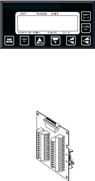
Front Panel Description
The display and touch keypad provide an intelligent way to operate the controller. The display has 16 alphanumeric or graphic characters per line. The 8-key keypad allows you to change the operating parameters, controller functions, and displays.
The information-packed displays show process variables, setpoints, and output levels for each loop. A bar graph display, single loop display, scanning display and an alarm display offer a real-time view of process conditions. Two access levels allow operator changes and supervisor changes.
WATLOW ANAFAZE CLS200
Figure 1.4 CLS200 Front Panel
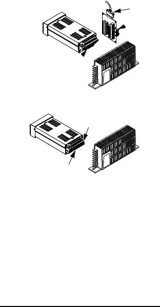
TB50
The TB50 is a screw-terminal interface for control wiring which allows you to connect relays, encoders and discrete I/ O devices to the CLS200. The screw terminal blocks accept
wires as large as 18 AWG (0.75 mm2). A 50-pin SCSI cable connects the TB50 to the CLS200.
Figure 1.5 TB50
8 |
Watlow Anafaze |
Doc.# 0600-3050-2000 |

CLS200 Series User’s Guide |
Chapter 1: System Overview |
CLS200 Cabling
Watlow Anafaze provides cables required to install your
CLS200. A 50-pin SCSI cable connects the TB50 to the
CLS200.
The optional cable used to connect the CLS200 to a computer using EIA/TIA-232 communications has a DB9 or DB25 connector for the computer and bare wires for connecting to the CLS200.
Safety
Watlow Anafaze has made every effort to ensure the reliability and safety of this product. In addition, we have provided recommendations that will allow you to safely install and maintain this controller.
External Safety Devices
The CLS200 controller may fail full-on (100% output power) or full-off (0% output power), or may remain full-on if an undetected sensor failure occurs. For more information about failed sensor alarms, see Failed Sensor Alarms on page 65.
Design your system to be safe even if the controller sends a 0% or 100% output power signal at any time. Install independent, external safety devices that will shut down the system if a failure occurs.
Typically, a shutdown device consists of an FM-approved high/low process limit controller that operates a shutdown device such as an mechanical contactor. The limit controller monitors for a hazardous condition such as an undertemperature or over-temperature fault. If a hazardous condition is detected, the limit controller sends a signal to open the contactor.
The safety shutdown device (limit controller and contactor) must be independent from the process control equipment.
WARNING! The controller may fail in a 0% or 100% power output state. To prevent death, personal injury, equipment damage or property damage, install external safety shutdown devices. If death or injury may occur, you must install FM-approved safety shutdown devices that operate independently from the process control equipment.
With proper approval and installation, thermal fuses may be used in some processes.
Doc.# 0600-3050-2000 |
Watlow Anafaze |
9 |
Chapter 1: System Overview |
CLS200 Series User’s Guide |
Power-Fail Protection
In the occurrence of a sudden loss of power, this controller can be programmed to reset the control outputs to off (this is the default). Typically, when power is re-started, the controller restarts to data stored in memory. If you have programmed the controller to restart with control outputs on, the memory-based restart might create an unsafe process condition for some installations. Therefore, you should only set the restart with outputs on if you are certain your system will safely restart. (See the Process Power Digital Input on page 79).
When using a computer or host device, you can program the software to automatically reload desired operating constants or process values on power-up. Keep in mind that these convenience features do not eliminate the need for independent safety devices.
Contact Watlow Anafaze immediately if you have any questions about system safety or system operation.
10 |
Watlow Anafaze |
Doc.# 0600-3050-2000 |

2 

Installation
This chapter describes how to install the CLS200 series controller and its peripherals. Installation of the controller involves the following procedures:
•Determining the best location for the controller
•Mounting the controller and TB50
•Power connection
•Input wiring
•Communications wiring (EIA/TIA-232 or EIA/TIA485)
•Output wiring
WARNING! Risk of electric shock. Shut off power to your entire process before you begin installation of the controller.
WARNING! The controller may fail in a 0% or 100% power output state. To prevent death, personal injury, equipment damage or property damage, install external safety shutdown devices. If failure may cause death or injury, you must install FM-approved safety shutdown devices that operate independently from the process control equipment.
Doc.# 0600-3050-2000 |
Watlow Anafaze |
11 |
Chapter 2: Installation |
CLS200 Series User’s Guide |
Typical Installation
Figure 2.1 shows typical installations of the controller with the TB50 and the TB18 terminal blocks. The type of terminal block you use greatly impacts the layout and wiring of your installation site. (See Figures 2.2 to 2.11.)
We recommend that you read this entire chapter first before beginning the installation procedure. This will help you to carefully plan and assess the installation.
CLS200 with TB50 |
SCSI Cable |
8 Digital Inputs,
 35 Digital Outputs
(Control/Alarm)
Pulse Input
Signal Inputs 
CLS200
Power supply
CLS200 with TB18
Signal Inputs
11 Digital Outputs (Control/Alarm) |
CLS200 |
2 Digital Inputs, 1 Digital/Pulse Input |
Power supply |
Figure 2.1 CLS200 System Components
Mounting Controller Components
Install the controller in a location free from excessive heat (more than 50º C [122° F]), dust, and unauthorized handling. Electromagnetic and radio frequency interference can induce noise on sensor wiring. Select locations for the CLS200 and TB50 such that wiring can be routed clear of sources of interference such as high voltage wires, power switching devices and motors.
NOTE! For indoor use only.
12 |
Watlow Anafaze |
Doc.# 0600-3050-2000 |

CLS200 Series User’s Guide |
Chapter 2: Installation |
WARNING! To reduce the risk of fire or electric shock, install the CLS200 in a controlled environment, relatively free of contaminants.
Recommended Tools
Use any of the following tools to cut a hole of the appropriate size in the panel.
•Jigsaw and metal file, for stainless steel and heavyweight panel doors.
•Greenlee 1/8-DIN rectangular punch (Greenlee part number 600-68), for most panel materials and thicknesses.
•Nibbler and metal file, for aluminum and lightweight panel doors.
You will also need these tools:
•Phillips head screwdriver
•1/8 in. (3 mm) flathead screwdriver for wiring
•Multimeter
Mounting the Controller
Mount the controller before you mount the terminal block or do any wiring. The controller’s placement affects placement and wiring considerations for the other components of your system.
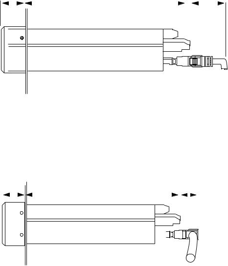
Ensure there is enough clearance for mounting brackets, terminal blocks, and cable and wire connections; the controller extends up to 7.0 inches (178 mm) behind the panel face and the screw brackets extend 0.5 inch (13 mm) above and below it. If using a straight SCSI cable, allow for an additional 1.6 inches (41 mm) beyond the terminal block. If using a right-angle SCSI cable, allow an additional 0.6 inch (15 mm). (See Figure 2.2 and Figure 2.3.)
Doc.# 0600-3050-2000 |
Watlow Anafaze |
13 |
Chapter 2: Installation |
CLS200 Series User’s Guide |
1.0 inch |
|
7.0 inches |
1.6 inch |
|||||
(25 mm) |
|
(178 mm) |
(41 mm) |
|||||
|
|
|
|
|
|
|
|
|
|
|
|
|
|
|
|
|
|
|
|
|
|
|
|
|
|
|
|
|
|
|
|
|
|
|
|
|
|
|
|
|
|
|
|
|
Figure 2.2 Clearance with Straight SCSI Cable
1.0 inch |
|
7.0 inches |
|
|
0.6 inch |
|||||||
(25 mm) |
|
(178 mm) |
|
|
(41 mm) |
|||||||
|
|
|
|
|
|
|
|
|
|
|
|
|
|
|
|
|
|
|
|
|
|
|
|
|
|
|
|
|
|
|
|
|
|
|
|
|
|
|
|
|
|
|
|
|
|
|
|
|
|
|
|
|
|
|
|
|
|
|
|
|
|
|
|
|
|
|
|
|
|
|
|
|
|
|
|
|
|
|
|
|
|
|
|
|
|
|
|
|
|
|
|
|
|
|
|
|
|
|
|
|
|
|
|
Figure 2.3 Clearance with Right-Angle SCSI
Cable
14 |
Watlow Anafaze |
Doc.# 0600-3050-2000 |
Loading...