


 Loading...
F4T Controller
Installation and Troubleshooting
User’s Guide
TOTAL
CUSTOMER
SATISFACTION
3YearWarranty
ISO 9001
1241 Bundy Boulevard., Winona, Minnesota USA 55987
Phone: +1 (507) 454-5300, Fax: +1 (507) 452-4507
http://www.watlow.com/F4T
Registered Company
Winona, Minnesota USA
1720-6742 Rev. A |
Made in the U.S.A. |
January 2019

Safety Information
We use note, caution and warning symbols throughout this document to draw your attention to important operational and safety information.
A “NOTE” marks a short message to alert you to an important detail.
A “CAUTION” safety alert appears with information that is important for protecting your equipment and performance. Be especially careful to read and follow all cautions that apply to your application.
A “WARNING” safety alert appears with information that is important for protecting you, others and equipment from damage. Pay very close attention to all warnings that apply to your application.
The safety alert symbol, (an exclamation point in a triangle ç) precedes a general CAUTION or WARNING statement.
The electrical hazard symbol, (a lightning bolt in a triangleÓ) precedes an electric shock hazard CAUTION or WARNING safety statement. Further explanations follow:
|
Symbol |
Explanation |
|
|
|
|
|
|
|
|
CAUTION: Warning or Electrical Hazard that needs further explana- |
ç |
|
Ó |
tion than label on unit can provide. Consult QSG for further infor- |
|
mation. |
||
CAUTION |
or |
Electrical |
AVERTISSEMENT: mise en garde ou danger qui demande plus de |
WARNING |
Shock Hazard |
précisions que l’information sur l’étiquette de l’unité. Consultez le |
|
|
|
|
manuel de l’utilisateur pour plus d’informations. |
|
|
|
Unit can be powered with either alternating current (ac) voltage or |
|
|
|
direct current (dc) voltage. |
|
|
|
ESD Sensitive product, use proper grounding and handling tech- |
|
|
|
niques when installing or servicing product. |
|
|
|
|
|
|
|
Do not throw in trash, use proper recycling techniques or consult |
|
|
|
manufacturer for proper disposal. |
|
|
|
|
|
|
|
Enclosure made of Polycarbonate material. Use proper recycling |
|
|
|
techniques or consult manufacturer for proper disposal. |
|
|
|
|
|
|
|
Unit is a Listed device per Underwriters Laboratories®. It has been |
|
|
|
evaluated to United States and Canadian requirements for Process |
|
|
|
Control Equipment. CSA 22.2#14, File 158031, UL 61010, File |
|
|
|
E185611 QUYX, QUYX7. . See: www.ul.com |
|
|
|
Unit is compliant with European Union directives. See Declaration |
|
|
|
of Conformity for further details on Directives and Standards used |
|
|
|
for Compliance. |
|
|
|
Unit has been reviewed and approved by Factory Mutual as a |
|
|
|
Temperature Limit Device per FM Class 3545 standard. See: www. |
|
|
|
fmglobal.com |

Symbol |
|
Explanation |
|
|
|
|
Unit has been reviewed and approved by CSA International for use |
|
|
as Temperature Indicating-Regulating Equipment per CSA C22.2 No. |
|
|
24. |
See: www.csagroup.org |
|
|
|
This F4T User’s Guide is copyrighted by Watlow Electric Manufacturing Company, © May 2016 with all rights reserved.
•© 2010-2012, QNX Software Systems Limited. All rights reserved.
•© 2008 -2014, Crank Software Inc. All rights reserved.
•Watlow® and TRU-TUNE® are registered trademarks of Watlow Electric Manufacturing Company.
•UL® is a registered trademark of Underwriter's Laboratories Incorporated.
•Modbus® is a registered trademark of Schneider Automation Incorporated.
•Vaisala® is a registered trademark of Vaisala OY Corporation.
•Microsoft® and Windows® are registered trademarks of the Microsoft Corporation. Quencharc® is a registered trademark of ITW Paktron.
10-07433 Rev. –

TC Table of Contents |
|
Chapter 1: Overview .. . . . . . . . . . . . . . . . . . . . . . . . . . . . . . . . . . . . |
.2 |
Available F4T Literature and Resources. . . . . . . . . . . . . . . . . . . . . . . . . |
. 2 |
Chapter 2: Install and Wire. . . . . . . . . . . . . . . . . . . . . . . . . . . . . . . . |
. 4 |
Getting Started Quickly.... .The Logical Approach. . . . . . . . . . . . . . . . . . . |
. 4 |
Dimensions. . . . . . . . . . . . . . . . . . . . . . . . . . . . . . . . . . . . . . . . . . . . . . . |
4 |
Installing the F4T . . . . . . . . . . . . . . . . . . . . . . . . . . . . . . . . . . . . . . . . . . |
. 5 |
Panel Mounting the Base. . . . . . . . . . . . . . . . . . . . . . . . . . . . . . . . . |
5 |
Flush Mounting the Base. . . . . . . . . . . . . . . . . . . . . . . . . . . . . . . . . |
6 |
Electrical Isolation .. . . . . . . . . . . . . . . . . . . . . . . . . . . . . . . . . . . . . . . . . |
8 |
Wiring the F4T Base.. . . . . . . . . . . . . . . . . . . . . . . . . . . . . . . . . . . . . . . . |
8 |
Power Requirements . . . . . . . . . . . . . . . . . . . . . . . . . . . . . . . . . . . . . . . |
. 9 |
Flex Module (FM) Characteristics . . . . . . . . . . . . . . . . . . . . . . . . . . |
. 9 |
Flex Module Installation. . . . . . . . . . . . . . . . . . . . . . . . . . . . . . . . . . . . . |
. 9 |
Wiring the Modules.. . . . . . . . . . . . . . . . . . . . . . . . . . . . . . . . . . . . . . . |
10 |
Communications Connections. . . . . . . . . . . . . . . . . . . . . . . . . . . . |
24 |
Chapter 3: Connecting a PC . . . . . . . . . . . . . . . . . . . . . . . . . . . . . . . . 25
Using the User Interface (UI) to Change or View Ethernet Settings.. . . 25
Understanding the Front Panel Navigational Buttons . . . . . . . . . . . 25
Connecting the F4T Base to a PC.. . . . . . . . . . . . . . . . . . . . . . . . . . . . . |
27 |
DHCP Connection. . . . . . . . . . . . . . . . . . . . . . . . . . . . . . . . . . . . . |
. 27 |
Fixed IP Connection. . . . . . . . . . . . . . . . . . . . . . . . . . . . . . . . . . . . |
27 |
Composer Software. . . . . . . . . . . . . . . . . . . . . . . . . . . . . . . . . . . . . . . |
28 |
Starting Composer Software.. . . . . . . . . . . . . . . . . . . . . . . . . . . . . |
28 |
Verifying Pluggable Flex Module Installation Using Composer.. . |
. 28 |
Chapter 4: Calibration. . . . . . . . . . . . . . . . . . . . . . . . . . . . . . . . . . . |
. 30 |
Calibrating the F4T Inputs . . . . . . . . . . . . . . . . . . . . . . . . . . . . . . . . . . |
. 30 |
Required Equipment When Performing Calibration . . . . . . . . . . . . . . . . |
30 |
Calibration of Analog Inputs.. . . . . . . . . . . . . . . . . . . . . . . . . . . . . . . . . |
31 |
Using Composer Software to Calibrate Analog Inputs. . . . . . . . . . . . . . |
32 |
Using the User Interface to Calibrate Analog Inputs. . . . . . . . . . . . . . . |
32 |
Chapter 5: Troubleshooting. . . . . . . . . . . . . . . . . . . . . . . . . . . . . . . |
. 33 |
Replacing the Battery. . . . . . . . . . . . . . . . . . . . . . . . . . . . . . . . . . . . . . . |
39 |
Chapter 6: Appendix . . . . . . . . . . . . . . . . . . . . . . . . . . . . . . . . . . . . |
. 41 |
F4T Base Specifications. . . . . . . . . . . . . . . . . . . . . . . . . . . . . . . . . . . . . |
41 |
F4T Base Ordering Information.. . . . . . . . . . . . . . . . . . . . . . . . . . . |
44 |
Flex Modules and Limit I/O Specifications. . . . . . . . . . . . . . . . . . . . . . . |
45 |
Flex Module - Mixed I/O Ordering Information. . . . . . . . . . . . . . . . |
48 |
Flex Module - Limit Ordering Information. . . . . . . . . . . . . . . . . . . |
49 |
Flex Modules - High Density I/O Specifications. . . . . . . . . . . . . . . . . . . 49
Flex Module - High Density Ordering Information. . . . . . . . . . . . . 53
Flex Module - Communications Ordering Information . . . . . . . . . . 53
How to Reach Us. . . . . . . . . . . . . . . . . . . . . . . . . . . . . . . . . . . . . . . . . . 56
Watlow F4T Install & Troubleshooting |
• 1 • |
Table of Contents |

1 |
Chapter 1: Overview |
||
Available F4T Literature and Resources |
|||
|
|
|
|
|
Document Title and Part Number |
Description |
|
|
|
|
This document looks deeper at the system |
|
F4T Setup and Operation User Guide, |
configuration using Composer™ software and |
|
|
the F4T function blocks and their connections. |
||
|
part number: 1680-2414 Rev. A |
||
|
Common product usage is described and illustrat- |
||
|
|
|
|
|
|
|
ed through application examples. |
|
F4T Specification Sheet, part number: |
Describes F4T hardware options, features, |
|
|
WIN-F4T-1118 |
benefits and technical specifications. |
|
|
|
|
|
|
|
|
Comprehensive guide to understanding thermal |
|
Watlow Application Guide |
principles, electrical noise, best practises for |
|
|
|
|
wiring industrial controls and much more. |
|
Watlow Support Tools DVD, part |
Contains all related user documents, tutorial |
|
|
videos, application notes and the application |
||
|
number: 0601-0001-0000 |
||
|
guide described above. |
||
|
|
|
|
To acquire one or more of these documents navigate to the Watlow website where you will have a choice to download free copies or purchase printed versions. Click on the link below to find your document of choice: http://www.watlow.com/F4T. For the Application Guide, click here: http://www.watlow.com/common/catalogs/files/appguide.pdf
Your Comments are Appreciated
In an effort to continually improve our technical literature and ensuring that we are providing information that is useful to you, we would very much appreciate your comments and suggestions. Please send any comments you may have to the following e-mail address: TechlitComments@watlow.com
Technical Assistance
If you encounter a problem with your Watlow controller, review your configuration information to verify that your selections are consistent with your application: inputs, outputs, alarms, limits, etc. If the problem persists, you should first contact the Original
Equipment Manufacturer (OEM) for assistance. If that is not an option you can also get assistance directly from Watlow:
•Contact a local representative: see last page
•Email: wintechsupport@watlow.com
•Call: 1-800-4WATLOW (1-800-492-8569) or +1 (507) 494-5656 from 7 a.m. to 5 p.m. Central Standard Time (CST) (Select options for Controls & Software and Technical Support)
Please have the following information available when calling:
• Complete model number |
• User’s Guide |
• All configuration information |
Watlow F4T Install & Troubleshooting |
• 2 • |
Chapter 1 Overview |

Warranty
This product is warranted by Watlow for a period of 36 months in accordance with the terms and conditions set forth on Watlow's website which can be accessed at www.watlow.com/terms.
Return Material Authorization (RMA)
1.Call Watlow Customer Service, (507) 454-5300, for a Return Material Authorization (RMA) number before returning any item for repair. If you do not know why the product failed, contact an Application Engineer or Product Manager. All RMA’s require:
•Ship-to address
•Bill-to address
•Contact name
•Phone number
•Method of return shipment
•Your P.O. number
•Detailed description of the problem
•Any special instructions
•Name and phone number of person returning the product.
2.Prior approval and an RMA number from the Customer Service Department is required when returning any product. Make sure the RMA number is on the outside of the carton and on all paperwork returned. Ship on a Freight Prepaid basis.
3.After we receive your return, we will examine it to verify the reason for the product failure. Unless otherwise agreed to in writing, Watlow's standard warranty provisions, which can be located at www.watlow.com/terms, will apply to any failed product.
4.In the event that the product is not subject to an applicable warranty, we will quote repair costs to you and request a purchase order from you prior to proceeding with the repair work.
5.Watlow reserves the right to charge for no trouble found (NTF) returns.
Document Overview and Purpose
The purpose of this document is to assist the installer in providing necessary information to mount, wire and power up the F4T controller. This document also provides information to assist in the process of diagnosing problems which might occur during or after the installation process.
Watlow F4T Install & Troubleshooting |
• 3 • |
Chapter 1 Overview |

2 Chapter 2: Install and Wire
Getting Started Quickly.... .The Logical Approach
The steps below outline installation and wiring for the base alone. More detail for each is provided in the following sections.
1.Using this document for orientation, find the base part number and note any installed options as well as input voltage requirements.
2.Mount/install the base in the panel (see instructions below for panel mount or flush mount options).
3.Ensure that incoming power is off and connect to the base power supply connector (see section "Wiring the F4T Base").
4.Make note of any I/O module slot dependencies installing each one into an appropriate base slot (see graphic entitled F4T Slot Dependencies under "Flex Module Installation").
5.Connect the wires from each field device to the associated I/O module connector (see section "Wiring the Modules").
6.Insert all wired I/O connectors onto the applicable modules and apply power to the base.
7.Connect the controller to a computer running Composer™ software using an Ethernet cable (see section "Connecting the F4T Base to a PC").
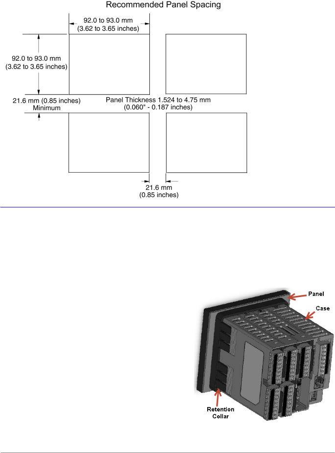
Dimensions
Panel Mount
Front View |
Side View |
Watlow F4T Install & Troubleshooting |
• 4 • |
Chapter 2 Install and Wire |
Dimensions (cont..)
Installing the F4T
Panel Mounting the Base
1.Make the panel cutout using the mounting template dimensions above and insert the case assembly into the panel cutout.
2.While pressing the case assembly firmly against the panel, slide the Retention Collar over the back of the controller until the gasket is compressed.
3.For an IP65 seal, alternately place and push the blade of a screwdriver against each of the the four corners of the retention collar assembly. Apply pressure to the face of the controller while pushing with the screwdriver. Don't be afraid to apply enough pressure to properly install the controller. The seal system is compressed more by mating the retention collar tighter to the front panel. If you can move the case assembly back and forth in the cutout, you
do not have a proper seal. The tabs on each side of the retention collar have teeth that latch into the ridges on the sides of the controller. Each tooth is staggered at a different depth from the front so that only one of the tabs, on each side, is locked onto the ridges at a time.
Watlow F4T Install & Troubleshooting |
• 5 • |
Chapter 2 Install and Wire |

Dimensions (cont..)
Flush Mounting the Base
1.Fabricate the mounting panel per the flush mount vertical or horizontal panel template
(shown below).
2.Press PEM standoffs (based on panel material) into mounting panel per supplier recommendations.
PEM Standoffs
PEM P/N |
S0-632-6 Z1 |
S0S-632-6 |
S0A-632-6 |
S04-632-6 |
|
|
Steel |
Stainless |
|
Hardened |
|
Material |
Aluminum |
Stainless |
|||
(Zinc Plated) |
Steel |
||||
|
|
Steel |
|||
|
|
|
|
3.Insert the controller through the flush mount bracket and lock it in place with the retention collar.
4.Mount flush mount bracket to back panel with (6) #6-32 screws.
5.Apply overlay to front panel.
Note:
Overlay is provided by the user.
Watlow F4T Install & Troubleshooting |
• 6 • |
Chapter 2 Install and Wire |

Dimensions (cont..)
Watlow F4T Install & Troubleshooting |
• 7 • |
Chapter 2 Install and Wire |
Electrical Isolation
|
|
|
|
No Isolation |
|
|
|
|
|
|
Digital Inputs & Outputs |
||
|
|
|
|
|||
Controller Power Supply |
|
|
|
|
|
|
|
|
|
|
|
|
|
24 to 28VÎ (dc) |
Safety Isolation |
|
|
|
|
|
24 to 28VÅ (ac) |
|
|
|
|
|
|
|
|
|
|
|
Switched DC, Open Collector, |
|
100 to 240VÅ (ac) |
|
|
|
No Isolation |
|
|
|
|
|
|
|
Process outputs |
|
|
|
|
|
|
|
|
|
|
|
|
|
|
|
Isolation |
|
|
|
Low-voltage |
|
|
|
|
|
|
Analog Inputs |
||
|
Controller |
|
Isolation |
|
||
|
|
|
|
|||
Safety |
|
Low Voltage Power Bus |
|
|
|
|
|
|
|||||
|
|
|
|
|
|
|
|
|
|
|
No Isolation |
USB Host |
|
|
|
|
|
|||
Mechanical Relay, |
|
|
|
|
|
|
|
|
|
|
|
|
|
Solid-State Relay, |
Safety Isolation |
|
|
|
|
|
NO-ARC Relay |
|
|
|
|
|
|
|
|
|
|
|
|
|
Outputs |
|
|
|
Low-voltage |
USB Device |
|
|
|
|
|
Isolation |
||
|
|
|
|
|
||
|
|
|
|
Low-voltage |
|
|
|
|
|
|
|
||
|
|
|
|
Ethernet Port |
||
|
|
|
|
Isolation |
||
|
|
|
|
|
||
|
|
|
|
|
|
|
|
|
|
|
|
||
|
|
|
Low-voltage Isolation: 42V peak |
|||
|
|
|
Safety Isolation: 2300VÅ (ac) |
|||
Wiring the F4T Base
Identify Connector Pinout
Power and Communications
Terminal |
Function |
98Power input: ac or dc+
99Power input: ac or dc-
- - - - |
- - - - |
|
|
CX |
Inter-module Bus A |
CY |
Inter-module Bus B |
CZ |
Inter-module Bus Common |
- - - - |
- - - - |
GND |
Functional earth ground |
Warning: Óç
Use National Electric (NEC) or other countryspecific standard wiring and safety practices when wiring and connecting this controller to a power source and to electrical sensors or peripheral devices. Failure to do so may result in damage to equipment and property, and/or injury or loss of life.
Avertissement : Óç
Utilisez les pratiques de câblage et de sécurité de National Electric (NEC) ou les normes spécifiques au pays lors du câblage et de
la connexion de ce régulateur à une source d'alimentation et aux capteurs électriques ou aux équipements périphériques. Tout manquement à cette règle pourrait provoquer des dégâts sur l'équipement et le matériel, et/ou des blessures personnelles ou des décès.
Watlow F4T Install & Troubleshooting |
• 8 • |
Chapter 2 Install and Wire |

Wire Size and Torque for Screw Terminations
•0.0507 to 3.30 mm2 (30 to 12 AWG) single-wire termination or two 1.31 mm2 (16 AWG)
•0.57 Nm (5.0 lb.-in.) torque
Power Requirements
•85 to 264VÅ (ac), (Models F4T _ _ [1, 2, 3, 4])
•20.4 to 30.8VÅ (ac) or Î (dc), (Models F4T _ _ [5, 6, 7, 8])
•50 to 60 Hz
•Power consumption 23W, 54VA
•Inter-module Bus (CX, CY, CZ)
•Do not route network wires with power wires. Connect inter-module bus wires in daisy-chain fashion when connecting multiple devices in a network
•The power supply within the controller base meets all power requirements for any and all inserted modules.
Flex Module (FM) Characteristics
Many of the modules appear to look alike at first glance, therefore, it is always recommended that the module part number be noted and verified
prior to plugging it into any of the available slots in a base. Each module is identified with a part number located on the back side of the assembly right below the connector (black label), as seen in the graphic to the right.
Flex Module Installation - To view video go to www.watlow.com/F4T
Some Flex Modules require that they be installed in specific slots within the base. As an example, if a communications card is to be installed, it must be placed in slot 6. Slot 6 can receive and accept any card, however, it is the only slot that allows for a communication card (see table to the right).
Slots are keyed such that modules cannot be inserted upside down. Insert modules with the component side facing the right when viewing the controller from the rear.
Installing the modules:
1.Note the part number to determine the types of inputs and outputs available to be connected in step 7.
2.Turn off power to the controller.
3.Select a slot for the module (see table to right). If replacing a module, remove the old module.
4.Affix corresponding slot number labels
(provided) to the module and to the removable screw terminal block.
Flex Module - Slot Dependencies
Module Type
Dual SSR *
FMHA-K
Communications
FMCA-(2)
Slot #
1 2 3 4 5 6
Y Y N Y Y N
N N N N N Y
All Other Modules |
Y Y Y Y Y Y |
|
|
Y = Allowed |
N = Not allowed |
* Reguires two adjacent slots
Watlow F4T Install & Troubleshooting |
• 9 • |
Chapter 2 Install and Wire |

5.With the component side of the module facing right (viewing the controller from the rear) insert the module in to the slot until it latches.
6.Remove the screw terminal block from the module.
7.Wire field devices to the appropriate terminals (see. Wiring details for each input and output are provided in the following sections.
8.Reconnect the wired screw terminal block to the module. Be sure to reconnect the terminal block to the correct module.
9.Restore power to the controller.
Note:
If a module is swapped out and replaced with a different type or moved to another open slot after configuration, the controller will no longer function properly without being reconfigured using Composer™ software.
Note:
To minimize the possibility of unwanted downtime due to a module being removed and installed into the wrong slot, affix the slot number labels (as directed in step 4 above) to each module (as shown in the graphic below, white circle) and each removable screw terminal block.
Wiring the Modules
Prior to wiring any of the I/O modules described in this document it is recommended that the warnings and notes listed below be reviewed.
CAUTION: ç
To prevent damage to the controller, do not connect wires to unused terminals.
AVERTISSEMENT: Pour prévenir tout endommagement du régulateur, ne pas faire de raccordements à des bornes inutilisées.
CAUTION ç Quencharc Note:
Switching pilot duty inductive loads (relay coils, solenoids, etc.) with the mechanical relay, solid-state relay or open collector output options requires the use of an R.C. suppressor for AC load or a diode for a DC load.
AVERTISSEMENT: les charges inductives de commutation de lampes témoins (bobines de relais, solénoïdes, etc.) avec des options de sortie à relais mécanique, de relais statique ou collecteur ouvert requièrent un dispositif antiparasite R.C.
Watlow F4T Install & Troubleshooting |
• 10 • |
Chapter 2 Install and Wire |
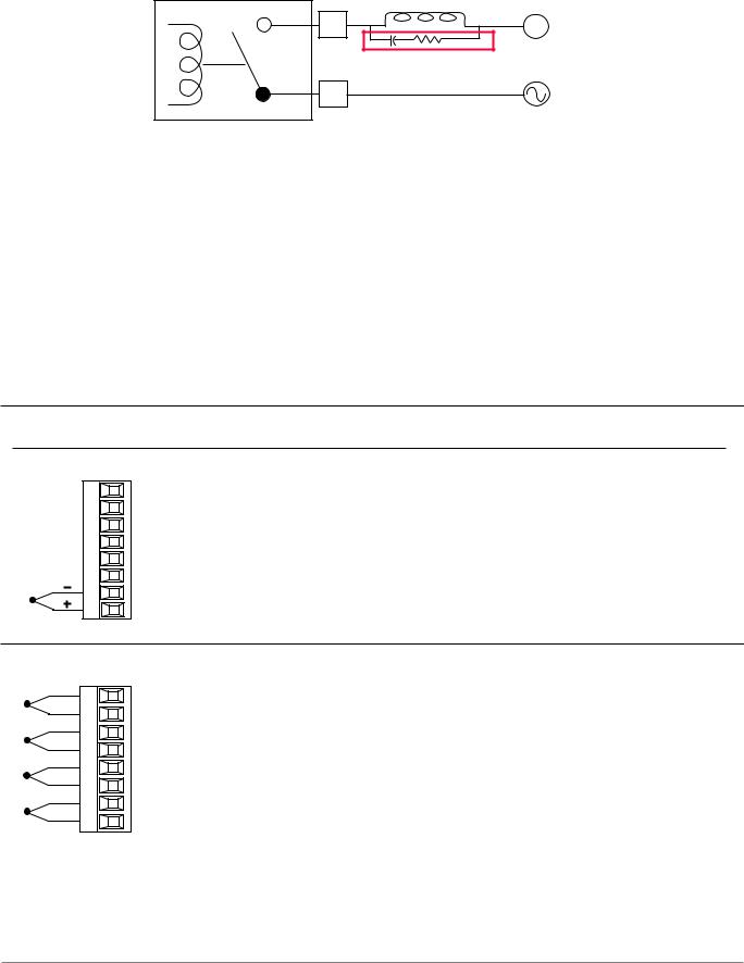
Place the Quencharc directly across the external coil as shown below. For a DC load, place the cathode of the diode, to the positive voltage of the load and the anode to the ground of the load.
User Load
L_ |
N |
Quencharc |
|
Watlow Part #: 0804-0147-0000 |
|
K_ |
|
Note:
It is possible that the terminal strip labeling for any given module could be the same. For example, if a Thermocouple input module is installed in slot 1 and 2, each slot would have S1 and R1 on its label. When referencing either of these inputs the differentiating factor is the module slot number, therefore the reference should be input 1 of slot number x.
Note:
Maintain electrical isolation between the analog input, digital input-outputs, switched dc/ open collector outputs and process outputs to prevent ground loops.
Note:
The F4T meets IP10 requirements when the empty slots have slot caps installed.
Note:
Maximum wire size and torque for screw terminations:
•0.0507 to 3.30 mm2 (30 to 12 AWG) single-wire termination or two 1.31 mm2 (16 AWG)
•0.57 Nm (5.0 lb.-in.) torque
Input Connections
Thermocouple
S1
R1
FM [M, L] A - [L, U, Y] _ _ A - A _ _ _
•Grounded or ungrounded sensors, greater than 20MΩ input impedance, 2kΩ source resistance max.
•3 microampere open-sensor detection
•Thermocouples are polarity sensitive. The negative lead (usually red) must be connected to S terminal
•To reduce errors, the extension wire for thermocouples must be of the same alloy as the thermocouple.
Thermocouple (High Density) FMHA - RAAA - A _ _ _
-S1
+R1
-S2
+R2
-S3
+R3 - S4
+R4
•Grounded or ungrounded sensors, greater than 20MΩ input impedance, 2kΩ source resistance max
•3 microampere open-sensor detection
•Thermocouples are polarity sensitive. The negative lead (usually red) must be connected to S terminal
•To reduce errors, the extension wire for thermocouples must be of the same alloy as the thermocouple
Watlow F4T Install & Troubleshooting |
• 11 • |
Chapter 2 Install and Wire |
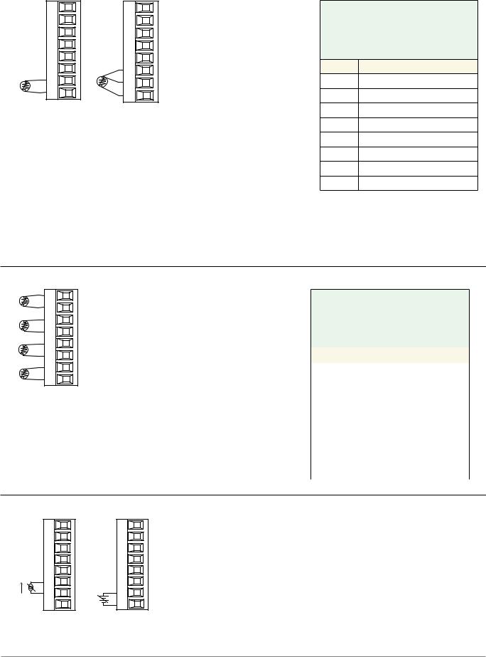
RTD
T1
S3 S1
S1 R1
2-wire RTD
FM [M, L] A - [L, U, Y*] _ _ A - A _ _ _
S2 T1
S3 S1
S1 R1
3-wire RTD
•2 or 3-wire platinum, 100 and 1,000 Ω @ 32°F (0°C) calibration to DIN curve
(0.00385 Ω/Ω/°C)
•RTD excitation current of 0.09 mA typical. Each ohm of lead resistance may affect the reading by 2.55°C for a 100 ohm platinum sensor or
0.25°C for a 1000 ohm sensor.
•For 3-wire RTDs, the S1 lead (usually white) must be connected to R1.
*This option does not support 3-wire RTDs
Lead Wire Resistance
Each wire for 2-Wire RTDs, not to exceed 10 ohms maximum.
AWG Ohms/1000ft
14 2.575
16 4.094
18 6.510
20 10.35
22 16.46
24 26.17
26 41.62
28 66.17
Note:
3-wire RTD's self-compensate for lead wire resistance up
to 10 Ω of wire resistance.
RTD (High Density) |
FMHA - RAAA - A _ _ _ |
S1
R1
S2
R2
S3
R3
S4
R4
2-wire RTD
•Platinum, 100 and 1,000 Ω @ 32°F (0°C) calibration to DIN curve (0.00385 Ω/Ω/°C)
•RTD excitation current of 0.09 mA typical. Each ohm of lead resistance may affect the reading by 2.55°C for a 100 ohm platinum sensor or 0.25°C for a 1000 ohm sensor (see table to right)
Lead Wire Resistance
Each wire for 2-Wire RTDs, not to exceed 10 ohms maximum.
AWG |
Ohms/1000ft |
14 |
2.575 |
16 |
4.094 |
18 |
6.510 |
20 |
10.35 |
22 |
16.46 |
24 |
26.17 |
26 |
41.62 |
28 |
66.17 |
Process
+ T1
 - S1
- S1
amperes
FM [M, L] A - [L, U] _ _ A - A _ _ _
•0 to 20 mA @ 100 Ω input impedance
•0 to 10VÎ (dc) @ 20 kΩ input impedance
•0 to 50 mVÎ (dc) @ 20 MΩ input impedance
•Scalable
- S1 + R1
volts
Watlow F4T Install & Troubleshooting |
• 12 • |
Chapter 2 Install and Wire |

Input Connections (cont..)
Process (High Density) |
FMHA - RAAA - A _ _ _ |
||
|
Volts |
Amps |
• 0 to 20 mA @ 100 Ω input impedance |
|
|
||
- |
S1 |
- S1 |
• 0 to 10VÎ (dc) @ 20 kΩ input impedance |
+ |
R1 |
+ R1 |
|
- |
S2 |
- S2 |
• 0 to 50 mVÎ (dc) @ 20 MΩ input impedance |
+ |
R2 |
+ R2 |
• Scalable |
- |
S3 |
- S3 |
|
+ |
R3 |
+ R3 |
|
- |
S4 |
- S4 |
|
+ |
R4 |
+ R4 |
|
Potentiometer |
FM [M, L] A - [L, U] _ _ A - A _ _ _ |
||
|
|
• Potentiometer: 0 to 1,200Ω |
|
CW S_
S_
CCW R_
Potentiometer (High Density) FMHA - RAAA - A _ _ _
CW S_ |
• Potentiometer: 0 to 1,200Ω |
CCW R_
CW S_
S_
CCW R_
CW S_
S_
CCW |
R_ |
CW S_
S_
CCW |
R_ |
Watlow F4T Install & Troubleshooting |
• 13 • |
Chapter 2 Install and Wire |

Input Connections (cont..)
Thermistor
S1
R1
FM [M, L] A - [M, T] AAA - A _ _ _
•>20 MΩ input impedance
•0 to 40kΩ, 0 to 20kΩ, 0 to 10kΩ, 0 to 5kΩ
•2.252kΩ and 10kΩ base at 77°F (25°C)
•Drive current is 109 μA as a constant current source
•User-selectable curves for Alpha Technics, BetaTHERM and YSI
•User-scaling support for Steinhart-Hart coefficients
Thermistor |
Base R |
Alpha |
Beta |
YSI |
|
Curve Setting |
@ 25 ºC |
Technics |
Therm |
||
|
|||||
Curve A |
2.252K |
Curve A |
2.2K3A |
004 |
|
Curve B |
10K |
Curve A |
10K3A |
016 |
|
Curve C |
10K |
Curve C |
10K4A |
006 |
|
|
Use Steinhart-Hart equation coefficients (A, B and |
||||
Custom |
C) from thermistor manufacturer corresponding to |
||||
the terms of the Steinhart-Hart equation: |
|||||
|
|||||
|
1 / T = A + Bln(R) + C (ln(R))3 |
|
|||
Thermistor (High Density) |
FMHA - PAAA - A _ _ _ |
S1
R1
S2
R2
S3
R3
S4
R4
•>20 MΩ input impedance
•0 to 40kΩ, 0 to 20kΩ, 0 to 10kΩ, 0 to 5kΩ
•2.252kΩ and 10kΩ base at 77°F (25°C)
•Drive current is 109 μA as a constant current source
•User-selectable curves for Alpha Technics, BetaTHERM and YSI
•User-scaling support for Steinhart-Hart coefficients
Thermistor |
Base R |
Alpha |
Beta |
YSI |
|
Curve Setting |
@ 25 ºC |
Technics |
Therm |
||
|
|||||
Curve A |
2.252K |
Curve A |
2.2K3A |
004 |
|
Curve B |
10K |
Curve A |
10K3A |
016 |
|
Curve C |
10K |
Curve C |
10K4A |
006 |
|
|
Use Steinhart-Hart equation coefficients (A, B and |
||||
Custom |
C) from thermistor manufacturer corresponding to |
||||
the terms of the Steinhart-Hart equation: |
|||||
|
|||||
|
1 / T = A + Bln(R) + C (ln(R))3 |
|
|||
Watlow F4T Install & Troubleshooting |
• 14 • |
Chapter 2 Install and Wire |

Input Connections (cont..)
Digital Input
B2
D2
FMLA - YEBA - A _ _ _
•Update rate 10Hz
•Voltage
-Max. input 36V at 3mA
-Input inactive when =< 2V
-Input active when => 3V at 0.25mA
•Dry contact
-Input inactive when =>
500Ω
-Input active when =<
100Ω
-Max. short circuit 13mA
Voltage Input |
|
|
|
|
|
Dry Contact |
|
|||||||||
|
|
common |
|
|
|
|
|
|
|
|
|
|
|
|||
|
B2 |
|
|
|
|
|
|
common |
|
|
||||||
|
|
|
|
|
|
|
|
|||||||||
|
|
|
|
|
|
|
|
|
|
|
B2 |
|
|
|||
|
|
|
|
|
|
|
|
|
|
|||||||
|
|
|
|
|
|
|
|
|
|
|
|
|
||||
|
|
|
|
|
|
|
|
|
|
|
|
|
|
|
|
|
|
|
|
|
|
|
|
|
|
|
|
|
|
|
|
|
|
Vdc
D2 |
D2 |
Vdc
Digital Input (High Density) |
FMHA - CAAA - A _ _ _ |
|
|
||||||
Common |
B1 |
• |
Voltage |
|
|
Voltage Input |
Dry Contact |
||
DC Input |
D1 |
|
- Max. input 36V at 3mA |
|
|
|
|||
DC Input |
D2 |
|
- |
Input inactive when =< |
B1 |
common |
|
||
DC Input |
D3 |
|
|
||||||
|
|
2V |
|
|
|
|
|||
DC Input |
D4 |
|
- |
|
when => 3V |
|
|
|
|
DC Input |
D5 |
|
Input active |
Vdc |
|
|
|||
DC Input |
D6 |
|
|
at 0.25mA |
|
|
|
D_ |
|
Internal Supply |
Z1 |
• |
Dry contact |
|
|
|
|
||
|
|
|
|
|
|
24 Vdc |
|||
|
|
|
- Input inactive when => |
D_ |
|
||||
|
|
|
|
|
|||||
|
|
|
|
500Ω |
|
|
|
|
|
|
|
|
- Input active when =< |
|
|
Z1 |
|||
|
|
|
|
100Ω |
|
|
|
|
|
|
|
|
|
|
|
|
|
|
|
|
|
|
- Max. short circuit 13mA |
|
|
|
|||
Current Transformer FMMA - C _ _ A - A _ _ _
T1
S1
•Input range is 0 to 50 mA (ac).
•Current transformer part number: 16-0246
•100 Ω input impedance
•Response time: 1 second maximum
•Accuracy +/-1 mA typical
Watlow F4T Install & Troubleshooting |
• 15 • |
Chapter 2 Install and Wire |
Loading...