


 Loading...
Series 942
User's Manual
TOTAL
CUSTOMER
SATISFACTION
1/4 DIN
Microprocessor-Based
Ramping Control
Watlow Controls
1241 Bundy Blvd., P.O. Box 5580, Winona, MN 55987-5580, Phone: 507/454-5300, Fax: 507/452-4507
W942-XUMN Rev. R00 |
$10.00 |
June, 1995 |
Made in the U.S.A. |
Supersedes:
W942-MA40-9305
 Printed on Recycled Paper
|
|
|
|
2 |
WATLOW Series 985 User's Manual |
Appendix |
|
Page |
Item |
|
|
Contents |
|
|
Chapter 1 |
|
|
|
|
|
|
|
|
|
|
4 |
Starting Out With The Watlow Series 942- |
|
|
|
|
4 |
General Description |
|
|
|
|
5 |
Opening the 942 |
Figures, Tables, Charts |
|
||
5 |
Set the DIP Switches |
Page |
Item |
Figure |
|
|
Chapter 2 |
4 |
Series 942 Input & Output Overview |
1 |
|
|
5 |
How to Open the Series 942 |
2 |
||
6 |
How To Install And Wire The Series 942- |
5 |
DIP Switch Location and Orientation |
3 |
|
6 |
System Planning |
6 |
Overview of the Series 942 |
4 |
|
6 |
Installation Information |
8 |
Series 942 Faceplate Dimensions |
5 |
|
7 |
Dimensional Information |
8 |
Series 942 Panel Cutout Dimensions |
6 |
|
8 |
Wiring The Series 942 |
8 |
Series 942 Sideview Dimensions |
7 |
|
8 |
Sensor Installation Guidelines |
9 |
120 VAC Power Wiring |
8 |
|
9 |
Input Wiring |
9 |
240 VAC Power Wiring |
9 |
|
11 |
Output 1 Wiring |
10 |
Thermocouple Wiring Diagram |
10 |
|
15 |
Output 2 Wiring |
10 |
RTD Wiring Diagram |
11 |
|
17 |
Auxiliary Wiring |
11 |
0 - 5 Process Input Wiring Diagram |
12 |
|
20 |
System Wiring Example |
11 |
4 - 20 Process Input Wiring Diagram |
13 |
|
|
Chapter 3 |
12 |
Solid State Relay, Output 1 Wiring |
14 |
|
|
12 |
DC (Open Collector) Output 1 Wiring |
15 |
||
21 |
How To Use the Keys And Displays |
13 |
6 Amp Mechanical Relay, Output 1 Wiring |
16 |
|
|
Chapter 4 |
13 |
4 - 20mA Process, Output 1 Wiring |
17 |
|
|
14 |
0 - 5VDC Process, Output 1 Wiring |
18 |
||
22 |
How To Setup The Series 942 |
14 |
S.S. Relay, w/o contact supp., Output 1 |
19 |
|
22 |
Entering The Setup Menu |
15 |
S.S. Relay, Output 2 Wiring Diagram |
20 |
|
23 |
Setup Parameters |
15 |
DC (open Collector), Output 2 Wiring |
21 |
|
28 |
Operation Menu and Parameters |
16 |
6A Mechanical Relay, Output 2 Wiring |
22 |
|
|
Chapter 5 |
16 |
S.S. Relay, w/o contact supp., Output 2 |
23 |
|
|
17 |
Auxiliary Option 1, 1 - 6 Amp Relay |
24 |
||
31 |
Programming the Seres 942 |
17 |
Auxiliary Option 2, 2 - 6 Amp Relays |
25 |
|
31 |
Program Menu |
18 |
Auxiliary Option 3, 6 Amp Relay/0-5ret. |
26 |
|
32 |
Program Parameters |
18 |
Auxiliary Option 4, 6 Amp Relay/4-20ret. |
27 |
|
34 |
Running the Series 942 |
19 |
Auxiliary Option 5, None/0-5Retransmit |
28 |
|
35 |
Resume a Profile |
19 |
Auxiliary Option 6, None/4-20mA Retransmit 29 |
||
36 |
Event Outputs |
20 |
System Wiring Example |
30 |
|
37 |
Multiple Profiles |
21 |
Series 942 Keys and Displays |
31 |
|
37 |
Jumploops |
22 |
Entering the Setup Menu |
32 |
|
38 |
Programming a Ramping Profile |
22 |
The Setup Menu |
33 |
|
38 |
Running Your Profile |
28 |
The Operation Menu |
34 |
|
39 |
Editing Your Profile |
31 |
The Program Menu |
35 |
|
|
Chapter 6 |
34 |
The Run Menu |
36 |
|
|
37 |
Guaranteed Soak Deviation Example |
37 |
||
|
How To Tune and Operate |
42 |
Auxiliary Jumper Location |
38 |
|
40 |
Tuning - Automatic and Manual |
43 |
Deviation Alarm Example |
39 |
|
42 |
Changing the Auxiliary Jumper Position |
43 |
Alarm Display Examples |
40 |
|
42 |
Using Alarms |
44 |
Error Code Display Example |
41 |
|
44 |
Error Code Messages & Actions |
53 |
Differential Mode Filter Wiring |
42 |
|
|
Appendix 1 |
53 |
Common Mode Filter Wiring |
43 |
|
|
53 |
Combination Filter Wiring |
44 |
||
46 |
Specification |
54 |
The Calibration Menu |
45 |
|
48 |
Model Number Information |
55 |
Calibration Parameters |
46 |
|
|
Appendix 2 |
|
|
|
|
49 |
Installation Guidelines For Preventing Noise |
|
|
|
Tables |
51 |
Eliminating Noise |
26 |
Input Ranges |
1 |
|
52 |
Checking For Ground Loops |
27 |
Setup MenuParameters/Description |
2 |
|
52 |
Noise Suppression Devices Available… |
30 |
Operation Menu Parameters/Description |
3 |
|
53 |
Line Filtering Configurations For Controls |
38 |
Series 942 Ramp and Soak Profile |
4 |
|
|
Appendix 3 |
39 |
Editing Your Profile, steps 4 - 7 |
5 |
|
54 |
Entering the Calibration Menu |
52 |
Noise Suppression Device Ratings |
6 |
|
56 |
Calibration Procedures |
57 |
RTD Settings |
7 |
|
64 |
Glossary |
|
|
|
|
66 |
Index |
|
|
|
Charts |
67 |
Warranty/Returns |
35 |
Master Step Chart |
1 |
|
|
|
|
|
|
|
Appendix |
WATLOW Series 985 User's Manual |
3 |
Starting Out
Chapter 1
The Watlow Series 942,
A Microprocessor-Based Control
Single Input -
Type J, K, T, N, R, S, B, C or Pt2
Thermocouple, RTD or Process
RS-422A, RS423A (RS-232C compatible), or EIA-485 Optional Computer Interface
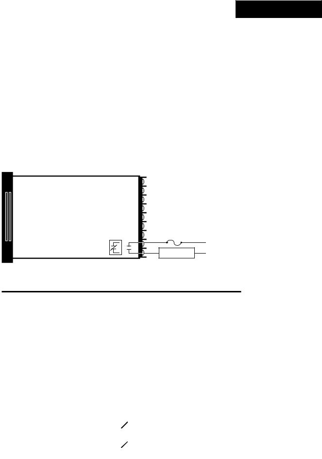
Figure 1 -
Series 942 Input and
Output Overview.
Dual Outputs-
PID or ON/OFF, User Selectable
Output 1
Heat or Cool
Output 1 Auto-tuning (Heat only)
Output 2
Heat, Cool or None
Dual Alarms/Events
Retransmit Output
(Up to 10 Slaves)
Process |
Set Point |
General Description
Welcome to the Watlow Series 942, a 1/4 DIN microprocessor-based ramping temperature control. It is a single input, dual output, auto-tuning control with 24 step program capability and easy fixed set point operation. The 942 accepts a Type J, K, T, N, R, S, B, C or Platinel 2 thermocouple, RTD, or process input. The primary output is heating or cooling, while the secondary output can be heating, cooling or none.
With the Series 942 you can select either PID or ON/OFF for Output 1 or 2. You can input a complete set of PID parameters for both outputs, including proportional band, reset/integral and rate/derivative. You can also select automatic tuning for Output 1 while in the heating mode. By setting either output's proportional band to zero, the Series 942 becomes a simple ON/OFF control with the switching differential selectable under the HYS Setup parameter.
Two optional auxiliary outputs may be alarms or events. An event is an ON/OFF mechanical relay output. Events are based on time, and can trigger peripheral equipment or processes. An optional retransmit output is offered in lieu of one of the auxiliary outputs. Select either retransmit of process variable or set point.
Operator-friendly features include automatic LED indicators to aid in monitoring and setup, as well as a calibration offset at the front panel. The Watlow Series 942 automatically stores all information in a non-volatile memory.
4 |
WATLOW Series 942 User's Manual |
Getting Started, Chapter 1 |
Starting Out
How to Open the 942
Before going further, open the Series 942 and pull the control chassis from its case. Here's how:
The control chassis fastens to the case with a single standard screw located on the
!
LOCK
Three strip connector plugs, in the rear of the control chassis, feed power and signals through the back of the case to the terminal strips. These plugs will let go as you pull.
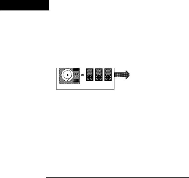
When removing the Series 942 control from its case, pull firmly but gently. When returning the control to the case, be sure you have the top up to match the plugs with the case. The 942 will not fit in the case upside down, but check to be sure it is oriented correctly. Press the unit in firmly, then turn the front panel screw clockwise to secure it. This insures proper electrical contact.
Figure 2 -
How to Open the Series 942.
! WARNING: The front panel screw turns 90° only. Do not apply excessive force or turn the screw more than 90°.
How to Set the DIP Switches
The Watlow Series 942 has a Dual In-line Package (DIP) switch inside the control on the A007-1954 circuit board (middle board). The location of the board and switch appear below. The switches are clearly numbered. When Switch #1 is ON, the Setup parameters can be viewed but not changed. When Switch #2 is ON, it provides battery backup of the Run parameters. When the control leaves the factory, both switches are OFF.
1 Hardware lockout of
1 Hardware Lockout of
Setup parameters
SETUP Parameters
22 Battery Disbackuphargeoforthe RunStorageparameters
(Factory default is OFF)
Control Chassis - Top View
Figure 3 -
DIP Switch Location
and Orientation.
NOTE:
The lithium battery has a life of approximately ten years. When the battery expires, Pout and Run are affected (see Chapters 4 & 5). Return the unit to the factory for a replacement.
Getting Started, Chapter 1 |
WATLOW Series 942 User's Manual 5 |

Installation
Chapter 2
How to Install and Wire the Series 942
NOTE:
Removing the Series 942 chassis from its case may make mounting easier.
System Planning
This chapter tells you how to install the Series 942. All mounting and wiring information is right here. Because Watlow controls are thoroughly tested and "burned in" before leaving the factory, the Series 942 is ready to install when you receive it.
But before you begin working, read through this chapter to gain an understanding of the entire installation. Consider sensor installation carefully. For detailed information you'll need to look at the noise reduction guidelines in the Appendix of this manual before making your panel cutout.
Installation Information
The Series 942 mounts in a panel cutout with two brackets, shipped with your control. These brackets hold the case against the front panel. The Series 942 behind-panel dimensions are 3.6" (90 mm) high by 3.6" (90 mm) wide by 6" (152 mm) deep. Figure 5 on the next page shows the dimensions of the front panel bezel. The 942 weighs 2.75 lbs. (1.25 kg) max.
For dimensional and mounting information, including the location of mounting brackets and size of the front panel cutout, see Figures 5 through 7 on the next page. Your panel's thickness can be from 0.06" (1.5 mm) to 0.25" (6.3 mm).
Installation Procedure
Follow this procedure to mount the Watlow Series 942 Temperature Control:
1.Make a panel cutout per the dimensions in Figure 6.
2.Remove the 942 from its case by turning the front panel screw 90° counterclockwise (CCW). Grip the bezel firmly and pull the control chassis out of the case.
!WARNING:
The front panel screw turns 90° only. Do not apply excessive force or turn the screw more than 90°.
!
3.Place the case in the cutout you just made.
4.Attach the mounting brackets either to the top and bottom, or to both sides of the unit.
5.Tighten the mounting brackets securely against your panel.
6.Insert the control chassis into its case and press the bezel to seat it. Turn the front panel screw 90° clockwise (CW) to lock the control in place. The hardware installation is complete. Proceed to the wiring section from here.
6 WATLOW Series 942 User's Manual |
Install and Wire, Chapter 2 |

0.92" 
 (23 mm)
3.81" sq. |
|
|
|
|
Dimensions |
||
|
|||||||
(97 mm) |
|
|
|
|
|
|
|
|
|
|
|
|
|
||
|
|
|
|
|
|
|
|
|
|
|
|
|
|
|
|
3.81" sq. (97 mm)
Figure 4 -
Series 942
Dimensions.
6.0" (152 mm)
Bezel
3.8" (97 mm)
Mounting Bracket |
3.6" ± 0.015" |
|
|
|
|
|
|
(90 mm ± 0.381)
3.622 to 3.653
3.62" to 3.65"
(92.00 to 92.79mm)
(92 to 93 mm)
Your Panel |
Panel |
|
|
|
Figure 5 - |
|
|
|
|
Series 942 |
|||
Your Panel |
Cutout |
|
|
|
Panel Cutout |
|
Thickness |
|
|
|
|||
Thickness: |
|
3.62" |
to 3.65" |
Dimensions. |
||
|
|
|
|
3.622 to 3.653 |
||
|
3.63" X 3.63" |
|
|
|||
0.06" to 0.25" |
|
|
(92 to 93 mm) |
|
||
3.625 x 3.625 |
|
|
(92.00 to 92.79mm |
|
||
0.06 to 0.25 |
(92.08 X 92.08 mm) |
|
|
|
|
|
|
|
|
|
|||
(1.52 to 6.35mm) |
(92.08 x 92.08mm) |
|
|
|
|
|
|
|
|
|
|
||
(1.524 to 6.35mm) |
Nominal |
|
|
|
|
|
|
|
|
|
|
||
k |
NOTE: |
|
|
|
|
|
All dimensions in inches. |
|
|||||
Install and Wire, Chapter 2 |
WATLOW Series 942 User's Manual |
7 |
|
Power Wiring
NOTE:
For 50 or 60Hz operation, no adjustment or jumper placement is necessary.
How to Wire the Series 942
The Series 942 wiring is illustrated by model number option. Check the terminal designation sticker on the control and compare your model number to those shown here and to the model number breakdown in the Appendix of this manual.
Series 942 internal circuits appear "inside" the line drawing of the 942, while connections and terminal designations appear "outside" the line drawing. All outputs are referenced to a de-energized state. The final wiring figure is a typical system example.
When you apply power without sensor inputs on the terminal strip, the Series 942 displays "- - - -" in the Upper display, and Er7 in the Lower display. This error indicates an open sensor or A/D error. Remove power to the control and connect the sensor properly, see Page 10. All wiring and fusing must conform to the National Electric Code and to any locally applicable codes as well.
Figure 6 -
120 VAC Power
Wiring.
CAUTION:
To avoid potential electric shock, use National Electric Code (NEC) safety practices when wiring and connecting this unit to a power source and to electrical sensors or peripheral devices.
Figure 7 -
240 VAC Power
Wiring.
|
|
|
Fuse |
||
11 |
|
|
|
|
L1 |
|
|
|
|
||
|
|
|
|
||
|
|
|
|
|
|
12 |
|
|
|
|
L2 |
|
|
|
|||
13 |
|
|
|
|
Earth Ground |
|
|
|
|
||
|
|
120 VAC |
|||
Fuse
10 
 L1
L1
Fuse
12 
 L2
L2
13 |
|
Earth Ground |
|
240 VAC
Sensor Installation Guidelines
We suggest you mount the sensor at a location in your process or system where it reads an average temperature. Put the sensor as near as possible to the material or space you want to control. The sensor should be thermally insulated from the sensor mounting.
8 |
WATLOW Series 942 User's Manual |
Install and Wire, Chapter 2 |

Input Wiring
Thermocouple Input |
|
||
Model # 942A |
- 1 _ |
_ _ - _ 000 |
942A - 3 _ _ _ - _ 000 |
942A |
- 2 _ |
_ _ - _ 000 |
942A - 4 _ _ _ - _ 000 |
Figure 8 -
Thermocouple
Input Wiring.
+
7
9 -
You must use an isolated or ungrounded thermocouple, if an external device with a nonisolated circuit common is connected to the 4-20mA or 0 - 5VDC output.
Extension wire for thermocouples must be of the same alloy as the thermocouple itself to limit errors.
RTD, 2 or 3 Wire
Model # 942A - 2 _ _ _ - _ 000 |
942A - 3 _ _ _ - _ 000 |
|
Jumper #5 to #6 |
Figure 9 - |
|
for 2-Wire RTD |
|
4 |
4 |
2 or 3 wire RTD |
Input Wiring. |
||
5 |
5 |
|
6 |
6 |
|
Long lead lengths create electrical resistance. There will be approximately +2° C input error for every 1Ω of lead length resistance, when using a two wire RTD. The resistance, when added to the resistance of the RTD element, will result in erroneous input to the instrument. To overcome this problem, use a three wire RTD sensor, which compensates for lead length resistance. When extension wire is used for a three wire RTD, all three extension wires must have the same electrical resistance. (i.e. same gauge, copper stranded).
Install and Wire, Chapter 2 |
WATLOW Series 942 User's Manual 9 |

Input Wiring
Figure 10 -
0 - 5VDC Process
Input Wiring.
NOTE:
When using a
0 - 5VDC process input, the input impedance is 100KΩ.
When using a process input such as 0 - 5VDC or 4 - 20mA, the rL and rH settings scale the display to match the measured range of the process signal.
An example of this is: A pressure transducer operates over a range of 0 - 300 PSI, delivering a 4 - 20mA output signal for this range. By setting rL = 0 and rH = 300, the Series 942 now displays a direct reading of pressure.
0 - 5VDC Process Input
Model # 942A - 2 _ _ _ - _ 000 |
942A - 3 _ _ _ - _ 000 |
1 |
+ |
|
|
|
|
|
|
|
|
|
|
VDC |
|
2 |
|
|
|
|
|
|
|
|
|
|
|
||
|
|
|
|
|
||
3 |
|
|
|
|
|
|
- |
|
|
|
|
|
|
|
|
|
|
|
|
Figure 11 -
4 - 20mA Process
Input Wiring.
NOTE:
When using a
4 - 20mA process input, the input impedance is 249Ω.
4 - 20mA Process Input
Model # 942A - 2 _ _ _ - _ 000 |
942A - 3 _ _ _ - _ 000 |
A jumper must be |
1 |
|
IDC |
|
+ |
installed between |
2 |
|
|
|
|
Terminals #2 and 3. |
3 |
|
|
|
- |
|
|
|
|||
|
|
|
10 |
WATLOW Series 942 User's Manual |
Install and Wire, Chapter 2 |
Output 1 Wiring
Solid State Relay With Contact Suppression, Output 1
Model # 942A - _ B _ _ - _ 000
Solid State Relay, Form A, 0.5 Amp
|
|
External |
|
17 |
N.O. |
Load |
L2 |
|
|
|
|
18 |
COM. |
|
L1 |
|
|
|
Fuse
Solid State Relay With Contact Suppression
Watlow's solid state relay changes state at zero volts, which is "zero-cross switching." They are also optically isolated, which means the output circuitry is energized by infrared light striking a photosensitive device. This results in a virtual absence of electrically generated noise, and provides electrical isolation between the input and output. For use in switching mercury relays or small AC loads. Off state impedance is 20KΩ minimum.
Figure 12 -
Solid State Relay
With Contact
Suppression,
Output 1 Wiring.
NOTE:
This output is supplied with an arc suppression snubber across the output terminals. High impedance loads may remain energized even though the output device is turned OFF.
Switched DC Output (Open Collector), Output 1
Model # 942A - _ C _ _ - _ 000
Switched DC, Open Collector, Non-Isolated
Logic |
16 |
- |
External |
|
|
||
Switch |
17 |
+ |
Load |
Switched DC
Watlow's solid state switch is a low current DC output (open collector) used to switch an external power switching device such as an SSR or an electromechanical relay. The input specifications of the power switching device must match those listed for the SS switch output. The power switching device must provide isolation between the SS switch output and load power since the SS switch output is a non-isolated output. Minimum load resistance is 500Ω. Available current is 22mA maximum. Typical voltage drop across a 1KΩ load is 12 to 19 volts.
Figure 13 -
Switched DC
(Open Collector),
Output 1 Wiring.
Install and Wire, Chapter 2 |
WATLOW Series 942 User's Manual |
11 |

Output 1 Wiring
Figure 14 -
6 Amp Mechanical
Relay, Output 1
Wiring.
NOTE:
This output is supplied with an arc suppression snubber across the output terminals. High impedance loads may remain energized even though the output device is turned OFF.
Mechanical Relay, 6 Amp, Form C, Output 1
Model # 942A - _ D _ _ - _ 000
Mechanical Relay, Form C, 6 Amp
16 |
COM. |
|
Fuse |
||||
|
|
|
|
L1 |
|||
17 |
N.O. |
|
|
|
|
|
L2 |
|
|
|
|
|
|||
18 |
N.C. |
|
External |
|
|||
|
|
|
|||||
|
Load |
|
|
||||
|
|
|
|
|
|||
Mechanical Relay
The electromechanical relay is an electrical and mechanical device with moving parts. When power is applied to the relay solenoid, contact closure is created through movement of the "common" contact of the relay.
Off state impedance is 20KΩ minimum.
Process, 0 - 10VDC, Output 1
Model # 942A - _ E _ _ - _ 000
Figure 15 -
Process, 0 - 10VDC, Process, 0-10VDC, Non-Isolated
Output 1 Wiring.
- |
16 |
- |
External |
+ |
|
+ |
|
17 |
Load |
Process Output
Proportional value determined by the control to balance the sensor input and set point. This value will fall between 0 - 10VDC depending on the thermal characteristics of the system.
Load impedance is 10KΩ minimum.
12 |
WATLOW Series 942 User's Manual |
Install and Wire, Chapter 2 |

Output 1 Wiring
Process, 4 - 20mA, Output 1
Model # 942A - _ F _ _ - _ 000
Figure 16 -
Process, 4 - 20mA,
Output 1 Wiring.
Process, 4-20 mA, Non-Isolated
+ |
17 |
+ |
External |
IDC |
18 |
|
|
- |
Load |
||
- |
|
|
|
Process Output
Proportional value determined by the control to balance the sensor input and set point. This value will fall between 4 - 20mA depending on the thermal characteristics of the system.
Load impedance is 600Ω maximum.
Process, 0 - 20mA, Output 1
Model # 942A - _ G _ _ - _ 000
Figure 17 -
Process, 0 - 20mA,
Output 1 Wiring.
Process, 0-20 mA, Non-Isolated
- |
16 |
- |
External |
IDC |
17 |
|
|
+ |
Load |
||
+ |
|
|
|
Process Output
Proportional value determined by the control to balance the sensor input and set point. This value will fall between 0 - 20mA depending on the thermal characteristics of the system.
Load impedance is 600Ω maximum.
Install and Wire, Chapter 2 |
WATLOW Series 942 User's Manual 13 |

Output 1 Wiring
Process, 0 - 5VDC, Output 1
Model # 942A - _ H _ _ - _ 000
Figure 18 -
Process, 0 - 5VDC,
Output 1 Wiring.
Process, 0-5VDC, Non-Isolated
+ |
17 |
+ |
External |
- |
18 |
|
|
- |
Load |
Process Output
Proportional value determined by the control to balance the sensor input and set point. This value will fall between 0 - 5VDC depending on the thermal characteristics of the system.
Load impedance is 10KΩ minimum.
Solid State Relay Without Contact Suppression, Output 1
Model # 942A - _ K _ _ - _ 000
Figure 19 -
Solid State Relay
Without Contact
Suppression, Output
1 Wiring.
Solid State Relay, Form A, 0.5 Amp
|
|
External |
|
17 |
N.O. |
Load |
L2 |
|
|
|
|
18 |
COM. |
|
L1 |
|
|
|
Fuse
Solid State Relay Without Contact Suppression
Watlow's solid state relay changes state at zero volts, which is "zero-cross switching." They are also optically isolated, which means the output circuitry is energized by infrared light striking a photosensitive device. This results in a virtual absence of electrically generated noise, plus output to input electrical isolation. Off state impedance is nearly infinite and should be used to switch high impedance non-inductive loads.
14 |
WATLOW Series 942 User's Manual |
Install and Wire, Chapter 2 |
Output 2 Wiring
Solid State Relay With Contact Suppression, Output 2
Model # 942A - _ _ B _ - _ 000
Solid State Relay, Form A, 0.5 Amp |
|
|
|
Fuse |
|||||||||
|
|
|
14 |
N.O. |
|
||||||||
|
|
|
|
|
L1L2 |
||||||||
|
|
|
|
|
|||||||||
|
|
|
|
COM. |
|
|
|
|
|
|
L1 |
||
|
|
|
|
|
15 |
|
|
|
|
|
|
||
|
|
|
|
|
|
|
|
|
|||||
|
|
|
|
|
|
|
|
||||||
|
|
|
|
|
|
|
|
External |
|
L2 |
|||
|
|
|
|
|
|
|
|
|
|||||
|
|
|
|
|
|
|
|
|
Load |
|
|||
Solid State Relay With Contact Suppression
Watlow's solid state relay changes state at zero volts, which is "zero-cross switching." They are also optically isolated, which means the output circuitry is energized by infrared light striking a photosensitive device. This results in a virtual absence of electrically generated noise, and provides electrical isolation between the input and output. For use in switching mercury relays or small AC loads. Off state impedance is 20KΩ minimum.
Figure 20 -
Solid State Relay
With Contact
Suppression,
Output 2 Wiring.
NOTE:
This output is supplied with an arc suppression snubber across the output terminals. High impedance loads may remain energized even though the output device is turned OFF.
Switched DC Output (Open Collector), Output 2
Model # 942A - _ _ C _ - _ 000
Switched DC, Open Collector, Non-Isolated |
|
|
|
|
|
Figure 21 - |
||
|
|
|
|
|
|
|
|
|
|
|
+ |
14 |
+ |
|
|
Switched DC Output |
|
|
Logic |
|
External |
(Open Collector), |
||||
|
- |
|
15 |
- |
|
|||
|
Switch |
|
|
Load |
Output 2 Wiring. |
|||
|
|
|
|
|
|
|
|
|
Switched DC
Watlow's solid state switch is a low current DC output (open collector) used to switch an external power switching device such as a SSR or an electromechanical relay. The input specifications of the power switching device must match those listed for the S.S. switch output. The power switching device must provide isolation between the S.S. switch output and load power since the S.S. switch output is a non-isolated output. Minimum load resistance is 500Ω. Available current is 9mA minimum and 22mA maximum.
Install and Wire, Chapter 2 |
WATLOW Series 942 User's Manual |
15 |
Output 2 Wiring
Mechanical Relay, 6 Amp, Form A, Output 2
Model # 942A - _ _ D _ - _ 000
Figure 22 -
6 Amp Mechanical
Relay, Output 2 |
Mechanical Relay, Form A, 6 Amp |
|
|
External |
|
|
||||||||
Wiring. |
|
|
|
|
|
|
|
|
|
|
||||
14 |
N.O. |
|
Load |
|
L1 |
|||||||||
|
|
|
|
|
|
|
|
|
|
|
|
|
|
L2 |
|
|
|
|
15 |
|
|
|
|
|
|
|
|
||
|
|
|
|
COM. |
|
|
|
|
|
L1 |
||||
|
|
|
|
|
|
|
|
|
|
|
|
|
|
L2 |
Fuse
NOTE:
This output is supplied with an arc suppression snubber across the output terminals. High impedance loads may remain energized even though the output device is turned OFF.
Mechanical Relay
The electromechanical relay is an electrical and mechanical device with moving parts. When power is applied to the relay solenoid, contact closure is created through movement of the "common" contact of the relay. Off state impedance is 20KΩ minimum.
Solid State Relay Without Contact Suppression, Output 2
Model # 942A - _ _ K _ - _ 000
Figure 23 - |
Solid State Relay, Form A, 0.5 Amp |
|
Fuse |
||||||||||
Solid State Relay |
|
|
|
|
|
14 N.O. |
|
|
|
|
|
L12 |
|
|
|
|
|
|
|
|
|
|
|
||||
Without Contact |
|
|
|
|
|
15 COM. |
|
|
|
|
|
|
L1 |
|
|
|
|
|
|
|
|
|
|
|
|||
Suppression, |
|
|
|
|
|
|
|
External |
|
L2 |
|||
Output 2 Wiring. |
|
|
|
|
|
|
|
|
|||||
|
|
|
|
|
|
|
|
Load |
|
|
|||
|
|
|
|
|
|
|
|
|
|
||||
Solid State Relay Without Contact Suppression
Watlow's solid state relays change state at zero volts, which is "zero-cross switching." They are also optically isolated, which means the output circuitry is energized by infrared light striking a photosensitive device. This results in virtual absence of electrically generated noise, while providing output to input electrical isolation. Off state impedance is nearly infinite and should be used to switch high impedance non-inductive loads.
16 |
WATLOW Series 942 User's Manual |
Install and Wire, Chapter 2 |
Auxiliary Wiring
For more information on alarms, alarm jumper selection and events, see Chapter 6.
Mechanical Relay
The electromechanical relay is an electrical and mechanical device with moving parts. When power is applied to the relay solenoid, contact closure is created through movement of the "common" contact of the relay. Off state impedance is 20KΩ minimum.
Mechanical Relay, 6 Amp, Single Form A or B, Auxiliary Output
Model # 942A- _ _ _ 1 - _ 000
Mechanical Relay, Form A or B, 6 Amp
26
Output #3 |
|
|
L1 |
27 |
Load |
L2 |
|
|
|
Mechanical Relay, 6 Amp, Dual Form A or B, Auxiliary Output
Model # 942A- _ _ _ 2 - _ 000
Mechanical Relay, Form A or B, 6 Amp |
|
|
|
|
|
|
||||||||||
|
|
|
|
|
|
|
|
|
|
|
24 |
Fuse |
|
|
||
Output #4 |
|
|
|
|
|
|
|
|
|
|
|
|
|
|
L1 |
|
|
|
|
|
|
|
|
|
|
|
25 |
|
|
|
|
|
|
|
|
|
|
|
|
|
|
|||||||||
|
|
|
|
|
|
|
Load |
|
L2 |
|||||||
|
|
|
|
|
|
|
|
|
|
|
26 |
|
Fuse |
|
|
|
Output #3 |
|
|
|
|
|
|
|
|
|
|
|
|
|
|
L1 |
|
|
|
|
|
|
|
|
|
|
|
27 |
|
|
|
|
|
|
|
|
|
|
|
|
|
|
|
||||||||
|
|
|
|
|
|
|
Load |
|
L2 |
|||||||
|
|
|
|
|
|
|
|
|
|
|
|
|
|
|
|
|
Figure 24 -
Auxiliary Option 1
Wiring.
NOTE:
This output is supplied with an arc suppression snubber across the output terminals. High impedance loads may remain energized even though the output device is turned OFF.
Figure 25 -
Auxiliary Option 2
Wiring.
Install and Wire, Chapter 2 |
WATLOW Series 942 User's Manual 17 |
Auxiliary Wiring
Mechanical Relay
The electromechanical relay is an electrical and mechanical device with moving parts. When power is applied to the relay solenoid, contact closure is created through movement of the "common" contact of the relay.
Mechanical Relay, 6 Amp, Form A or B/0 - 5VDC Retransmit
Model # 942A- _ _ _ 3 - _ 000
Figure 26 -
Auxiliary Option 3
Wiring.
NOTE:
This output is supplied with an arc suppression snubber across the output terminals. High impedance loads may remain energized even though the output device is turned OFF.
Process, 0-5VDC, Non-Isolated |
|
|
|
|
|
|
|
|
|
|
|
|
|
|
|||||||||||
Mechanical Relay, Form A or B, 6 Amp |
|
|
|
|
|
- |
|
|
|
|
|
|
|||||||||||||
|
|
|
|
|
|
|
|
External |
|||||||||||||||||
|
|
|
|
|
+ |
|
|
|
|||||||||||||||||
|
|
|
|
|
|
|
|
|
|
|
|
24 |
|
|
|
|
|
Load |
|||||||
Output #4 |
|
|
|
|
|
|
- |
|
|
|
|
|
|
|
|
|
|
|
|||||||
|
|
|
|
|
25 |
|
|
|
Fuse |
|
|
|
|||||||||||||
|
|
|
|
|
|
|
|
|
|
|
|
|
|
||||||||||||
|
|
|
|
|
|
|
|
|
|
|
|
|
|
||||||||||||
Output #3 |
|
|
|
|
|
|
+ |
|
|
|
26 |
|
|
|
|
|
L1 |
||||||||
|
|
|
|
|
|
|
|
|
|
|
|
|
|
|
|
|
|
|
|
|
|
|
|||
|
|
|
|
|
|
|
|
|
27 |
|
|
|
|
|
|
|
|
|
|
||||||
|
|
|
|
|
|
|
|
Load |
|
|
L2 |
||||||||||||||
|
|
|
|
|
|
|
|
|
|
|
|
|
|
|
|
|
|
|
|
|
|
|
|
|
|
Load impedance 10KΩ mimimum.
Mechanical Relay, 6 Amp, Form A or B/4 - 20mA Retransmit
Model # 942A- _ _ _ 4 - _ 000
|
Process, 4-20 mA, Non-Isolated |
|
|
|
|
|
|
|
|
|
|
|
|
|
|
|||||||||
Figure 27 - |
Mechanical Relay, Form A or B, 6 Amp |
|
|
|
|
|
+ |
|
|
|
|
|
|
|||||||||||
|
|
|
|
|
|
|
|
|
|
|
||||||||||||||
Auxiliary Option 4 |
|
|
|
|
|
|
|
|
|
|
|
|
|
|
|
|
|
|
External |
|||||
|
|
|
|
|
|
|
|
|
|
|
|
|
|
|
|
- |
|
|
|
|||||
Wiring. |
|
- |
|
|
|
|
24 |
|
|
|
|
Load |
||||||||||||
|
IDC |
|
|
25 |
|
|
|
|
|
|
|
|
|
|||||||||||
|
|
|
Fuse |
|
|
|
||||||||||||||||||
|
|
|
|
|
|
|
||||||||||||||||||
|
|
+ |
|
26 |
|
|
|
|
L1 |
|||||||||||||||
|
|
|
|
|
|
|
|
|
|
|
|
|
|
|
|
|
|
|
|
|
|
|
|
|
|
|
|
|
|
|
|
|
|
|
|
27 |
|
|
|
|
|
|
|
|
|
||||
|
|
|
|
|
|
|
|
|
|
|
|
|
Load |
|
|
L2 |
||||||||
|
|
|
|
|
|
|
|
|
|
|
|
|
|
|
|
|
|
|
|
|||||
|
|
|
|
|
|
|
|
|
|
|
|
|
|
|
|
|
|
|
|
|
|
|
|
|
Load impedance 600Ω maximum.
18 |
WATLOW Series 942 User's Manual |
Install and Wire, Chapter 2 |

Auxiliary Wiring
Retransmit Output
When using a retransmit output such as 0 - 5VDC or 4 - 20mA, the rL and rH settings scale the range of the retransmit output.
An example of this is: By setting rL = 0, rH = 1000 and Ot4 = PrOC a process value of 500 will result in a retransmitted signal of 2.5VDC or 12mA.
0 - 5VDC Retransmit, Auxiliary Output
Model # 942A- _ _ _ 5 - _ 000
Figure 28 -
Auxiliary Option 5
Wiring.
Process, 0-5VDC non-isolated
- |
24 |
- |
External |
|
25 |
+ |
|
+ |
Load |
||
|
|
|
Load impedance 10KΩ mimimum.
4 - 20mA Retransmit, Auxiliary Output
Model # 942A- _ _ _ 6 - _ 000
|
Figure 29 - |
Process, 4-20 mA, Non-Isolated |
Auxiliary Option 6 |
Wiring. |
|
- |
|
|
24 |
+ |
|
|
|
|
|
|
External |
|||||||
IDC |
|
|
|
25 |
- |
|
|
||
|
|
|
|
Load |
|||||
|
|
+ |
|
|
|
||||
|
|
|
|
|
|
|
|
|
|
Load impedance 600Ω maximum |
|
|
|
|
|
|
|||
Install and Wire, Chapter 2 |
WATLOW Series 942 User's Manual |
19 |
Loading...