


Electrically Released Brake ER-375, ER-475, ER-650 with Pin Drive Armatures
P-253 819-0315
Installation Instructions
Contents
Introduction . . . . . . . . . . . . . . . . . . . . . . . . . . . . .2 Installation Instructions . . . . . . . . . . . . . . . . . . . .3 Power Supplies/Brake Release Adjustment . . . . .4 Autogap Adjustment . . . . . . . . . . . . . . . . . . . . . .5 Operating Instructions . . . . . . . . . . . . . . . . . . . . .6 Dimensions and Specifications . . . . . . . . . . . . . .8 Bushing Part Numbers . . . . . . . . . . . . . . . . . . . .9 Exploded View . . . . . . . . . . . . . . . . . . . . . . . . .10 Component Parts/How to Order . . . . . . . . . . . .11 Warranty . . . . . . . . . . . . . . . . . . . . . . .Back Page
 Failure to follow these instructions may result in product damage, equipment damage, and serious or fatal injury to personnel.
Introduction
This service manual tells how to install, adjust, and maintain your Warner Electric brake. It also contains information for part replacements when needed.
Warner Electric Electrically Released Brakes are high performance, high torque units. After carefully reading these instructions, no assembly or installation difficulties should be encountered. Warner Electric Electrically Released brakes function on the same principle of "response to magnetic attraction" that operates other Warner Electric brakes and clutches. Braking torque in these brakes depends on ceramic permanent magnets which have a high resistance to demagnetization. With the power off, the unit produces full braking torque. The brake is released by generating an electromagnetic field which opposes the field produced by the permanent magnets.
Basic Mechanical Considerations
Electrically released brakes require special mounting considerations. Please review the items listed below prior to starting installation per Step 1.
a)If the magnet mounting surface is a magnetic material, the magnet must be insulated approximately 1/2 inch from that surface with a plate or spacers of non-magnetic material.
b)Caution must be exercised when the armature is moved close to the magnet assembly since the permanent magnets create a very strong attractive force. Injury may result if fingers are in between the armature and magnet when the gap is 1/2" or less.
2 Warner Electric • 800-825-9050 |
P-253 • 819-0315 |
Installation Instructions
A. Customer Shall Maintain:
1.Squareness of brake mounting face with armature hub shaft within .006 T.l.R.
2.Concentricity of brake mounting pilot diameter with armature hub shaft within
.010 T.l.R.
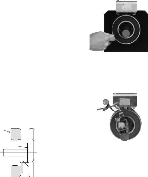
B. Mounting the Magnet
The brake magnet is mounted to a stationary machine member by a flange. Extreme care must be taken in selecting the location for the mounting of the magnet. Proper positioning is very important for the unit to function correctly.
1.A pilot diameter on the mounting surface is essential to hold the magnet within the required tolerances. (See Figure 1)
Pilot Diameter 
Mounting Surface
Figure 1
2.A machined pilot diameter is provided on the magnet mounting flange (See Figures 1, 2, & 3) to aid in the proper positioning of the
magnet.
3.Once the mounting surface has been prepared the magnet is bolted in place with capscrews and lockwashers. (See Figure 2)
Figure 2
4.Use a dial indicator to check the unit for concentricity and squareness to the shaft. The unit should be concentric within .010 T.l.R. and square within .006 T.l.R. (See Figure 3)
Figure 3
C. Armature To Shaft Assembly
Check to insure that all parts are clean and free from burrs or chips. Insert the key into the shaft keyway. Place the bushing into the hub and match half holes to make complete holes. Each hole will be threaded on one side only. Place the screws loosely into the holes which are threaded on the hub side. Slip the assembly onto the shaft and position it so the armature is in contact with
the magnet.
 Keep fingers clear of area between the magnet and the armature as the armature will be puIled sharply toward the magnet after the gap is closed to approximately 1/8 inch.
Warner Electric • 800-825-9050 |
P-253 • 819-0315 3 |
Tighten the screws alternately and evenly until all are pulled up very tightly. Tap against the large end of the bushing with a plastic hammer to avoid damaging the bushing. The screws can then be tightened again, using the following torque specifications:
ER-475 |
55 in. Ib. |
ER-650 |
175 in. Ib. |
Repeat this alternate tapping and retightening until the specified wrench torque no longer turns the screws.
To disassemble, remove both screws and reinsert one screw in the vacant hole (threads on bushing). Tighten this screw until the bushing is loosened in the hub. If the bushing does not loosen, tap on the hub.
D. Power Supplies
The ER style electrically released brakes are designed to operate with an adjustable voltage power supply because the voltage at which the individual brakes will release can vary slightly from brake to brake. The output voltage needs to be adjusted to obtain the optimum release point. Warner Electric offers two different model power supplies, either of which can be used to operate the ER style brakes. They are the MCS-103-1
or the CBC-200. Refer to the control operation manual for instructions on how to wire the control.
E. Brake Release Adjustment
Instructions for setting the optimum release voltage of permanent magnet applied electrically released brakes.
 The following procedure will result in the brake releasing and allowing the load to be free to move. Be sure the load is in a safe condition before proceeding with this process.
In a permanent magnet applied/electrically released brake, the attractive force between the
brake surfaces is created by permanent magnets. The brake is electrically released by applying DC power to the electro-magnetic coil in the brake that opposes the permanent magnets. Electrically released brakes are polarity sensitive: the positive lead of the power supply must be connected to the positive lead of the brake, and the negative lead of the power supply must be connected to the negative lead of the brake. The power supply applied to the brake must be adjustable so that the optimum release voltage for each individual brake can be determined and set.
The following procedure describes how to set the adjustable power supply to the optimum release point of the brake. A volt-meter is required to perform the procedure.
 No power is applied to motor during this procedure. Power normally supplied by motor to brake control should be supplied by alternate method.
After control is adjusted per steps below, brake control may need to be fine tuned (adjusted) with motor running to compensate for any changes in supply voltage used.
1.With power off, connect the positive lead of the power supply to the positive lead of the brake and the negative lead of the power supply to the negative lead of the brake.
2.Connect a volt-meter to measure the voltage applied across the brake.
3.Adjust the power supply to its lowest possible output, then energize the power supply only, to apply power to the brake.
4.Starting from the low point, slowly increase the applied voltage until the brake armature disengages from the magnet. Note and record the applied voltage at this point.
4 Warner Electric • 800-825-9050 |
P-253 • 819-0315 |
 Loading...