


EM-50

P-213
819-0303
Electro-Module EM-50,
EM-100, EM-180, EM-210, EM-215
Service & Installation Instructions
An Altra Industrial Motion Company

Contents
Pre-Installation Instructions
Pre-Installation Instructions . . . . . . . . . . . . . . . .2
Installation Instructions . . . . . . . . . . . . . . . . . . .4
Setting Airgap . . . . . . . . . . . . . . . . . . . . . . . . . .5
Electrical Coil Data . . . . . . . . . . . . . . . . . . . . . .8
Burnishing . . . . . . . . . . . . . . . . . . . . . . . . . . . . .9
Troubleshooting . . . . . . . . . . . . . . . . . . . . . . . . .9
Maintenance . . . . . . . . . . . . . . . . . . . . . . . . . . .9
Overhung Load Data . . . . . . . . . . . . . . . . . . . .11
Dimensions and Specifications
EM-50-10 . . . . . . . . . . . . . . . . . . . . . . . . . .12
EM-100-10 . . . . . . . . . . . . . . . . . . . . . . . . .12
EM-180-10 . . . . . . . . . . . . . . . . . . . . . . . . .12
EM-210-10 . . . . . . . . . . . . . . . . . . . . . . . . .12
EM-50-20 . . . . . . . . . . . . . . . . . . . . . . . . . .13
EM-100-20 . . . . . . . . . . . . . . . . . . . . . . . . .13
EM-180-20 . . . . . . . . . . . . . . . . . . . . . . . . .13
EM-210-20 . . . . . . . . . . . . . . . . . . . . . . . . .13
EM-215-20 . . . . . . . . . . . . . . . . . . . . . . . . .13
EM-50-30 . . . . . . . . . . . . . . . . . . . . . . . . . .14
EM-100-30 . . . . . . . . . . . . . . . . . . . . . . . . .14
EM-180-30 . . . . . . . . . . . . . . . . . . . . . . . . .14
EM-210-30 . . . . . . . . . . . . . . . . . . . . . . . . .14
EM-50-40 . . . . . . . . . . . . . . . . . . . . . . . . . .15
EM-100-40 . . . . . . . . . . . . . . . . . . . . . . . . .15
EM-180-40 . . . . . . . . . . . . . . . . . . . . . . . . .15
EM-210-40 . . . . . . . . . . . . . . . . . . . . . . . . .15
EM-10-20 . . . . . . . . . . . . . . . . . . . . . . . . . .16
EM-10-40 . . . . . . . . . . . . . . . . . . . . . . . . . .17
EM-20-30 . . . . . . . . . . . . . . . . . . . . . . . . . .18
EM-30-40 . . . . . . . . . . . . . . . . . . . . . . . . .19
NEMA Frame Standards . . . . . . . . . . . . . .20
Warranty . . . . . . . . . . . . . . . . . . . .Back Page
A. Before installing the Electro-Module to a
motor or reducer, make certain that the EM
size and NEMA frame dimensions match
according to Table 1.
Corresponding
EM NEMA Shaft C-Face
Size Frame Sizes Dia. Pilot Dia.
50 48Y/56C 5/8 4-1/2
100 48Y/56C 5/8 4-1/2
180 143TC/145TC 7/8 4-1/2
210 182TC/213TC 1-1/8 8-1/2
215 213TC/215TC 1-3/8 8 1/2
Table 1
B. Check the motor for shaft endplay. If the
shaft can be moved axially .030” or more, the
module should not be installed since excessive thrust may occur between the rotor and
field. The motor should not be used unless
the endplay can be reduced.
C. Install your specific modular combination
according to the installation steps specified
in Table 2. Use only those steps indicated for
each combination.
Failure to follow these instructions may result in product damage, equipment
damage, serious or fatal injury to personnel.
Warner Electric • 800-825-9050 P-213 • 819-0303
2
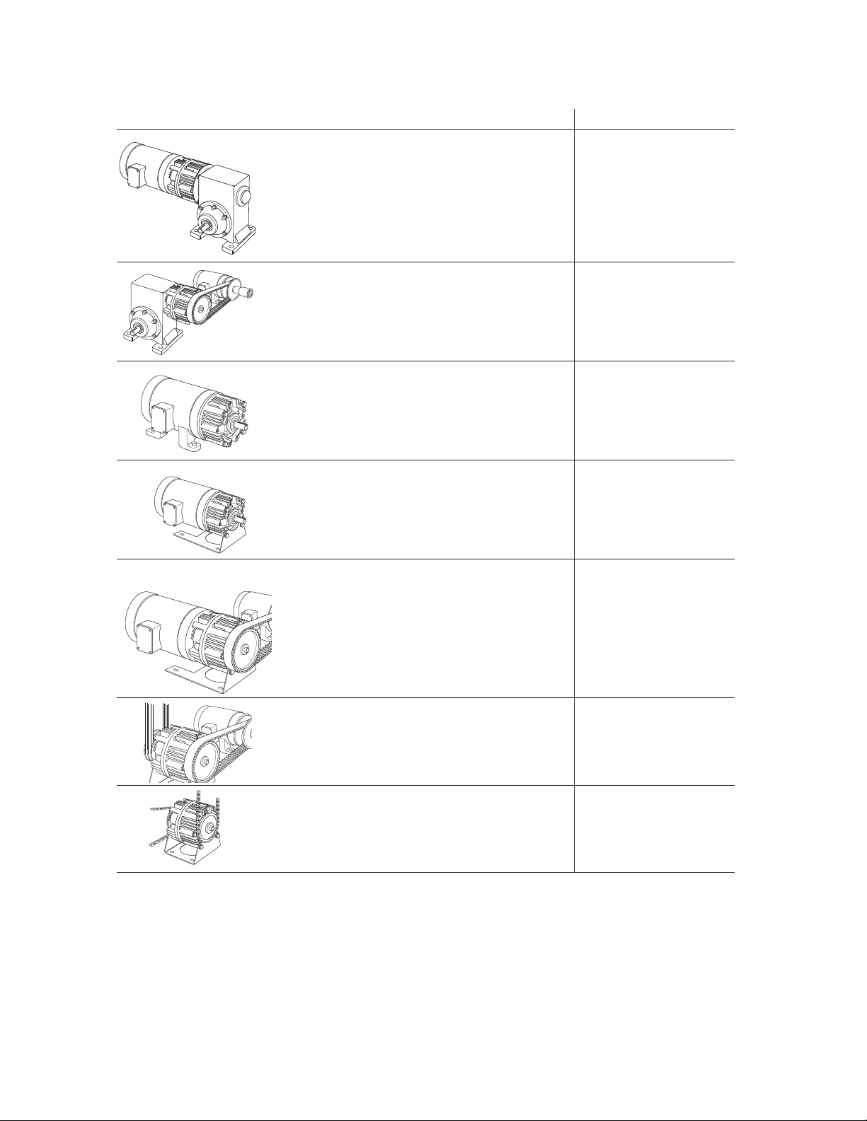
For these EM combinations: Use sections:
Electro Module Clutch-Brake Between A, B, C, G, H, I
C-Face Motor and Reducer – 10-20
Electro Module Clutch Between A, B, C, G, H, I
Motor and Reducer – 10-40
Electro Module Clutch Brake – 20-30 B, C, G, H, I
Electro Module Clutch – 30-40 B, C, G, H, I
Electro Module Brake D, C, G, H, I
on C-Face Motor – 20
Motor Mount Electro Module C, E, H, I
Clutch-Brake on C-Face Motor – 20-M
Motor Mount Electro Module ClutchBrake on C-Face Motor – 10-20-M A, B, C, E, H, I
Motor Mount Electro Module Clutch A, B, C, E, H, I
on C-Face Motor – 10-40-M
Base-Mounted B, C, F, H, I
Electro Module Clutch-Brake – 20-30-B
Base-Mounted B, C, F, H, I
Electro Module Clutch – 30-40-B
Table 2
Warner Electric • 800-825-9050 P-213 • 819-0303
3

Installation Instructions
Section A: Mounting the Motor Clutch Module
(10 Module)
1. Examine the clutch adapter. Note that there
are gaps between the housing fins on roughly
half of the circumference of the unit. Mount
the clutch adapter with the open gaps down.
This will keep contaminants from falling into
the unit. There are four screws and washers.
These will be bolted through the adapter onto
the four holes in the face of the motor (See
Figure 1).
3. Slide the rotor onto the motor shaft. (See
Figure 3) Make sure the rotor hub slides
easily onto the shaft. If the fit is too tight,
polish the shaft with emery paper so the hub
will slide on easily. Do not use a hammer or
force the rotor hub onto the shaft. Slide the
rotor back off the shaft.
Figure 1
2. Look at the back side of the rotor and note
there are cardboard spacer buttons as
depicted in figure 2.
Figure 2
Figure 3
4. Insert key onto the shaft. Prick punch the
motor shaft keyway at the end of the key to
prevent the key from sliding out. Slide the
rotor onto the motor shaft until it bottoms
against the field.
5. Using an Allen Wrench securely tighten the
two setscrews in the rotor hub. (See Figure 4)
When the motor is turned on, the spacer buttons will quickly wear away and provide the
proper gap between the field and rotor. The
setscrews are accessible from the front of the
rotor on sizes 100, 180, 210, and from behind
the rotor on size 50 units.
Figure 4
Warner Electric • 800-825-9050 P-213 • 819-0303
4

Section B: Bolting Two Modules Together
The brake module (20) and/or output clutch
module (40) may be assembled to the mounted
motor clutch module (10) or the input clutch (30).
1. Position the modules so that, in the usual
horizontal position, the ventilation holes are
down to prevent foreign matter from falling
into the units.
2. Bolt the modules together with the long hex
head bolts that are provided, see figure 5.
Mating pilot diameters assure proper alignment between module assemblies.
3. Proceed to Section C
Figure 6
Figure 5
Section C: Adjusting Airgap
For new installations it is necessary to adjust the
airgap between the friction faces of the clutch
and/or brake.
To set the airgap for an Electro-Module (EM) you
will need to access the armatures. On an EM
there are gaps between the fins on the housing
on 1/2 of the unit circumference. When looking
through this gap, you will see the fan on the
clutch rotor. In that fan there is a 1/2 x 1 inch
window. It is possible to look inside the unit and
see the armatures by looking through this window. When looking through this window you will
be looking between the two armatures of a
clutch/brake unit as shown in figures 6 and 7.
Figure 7
If the armature for either the clutch or the brake
is too far away from its mating friction surface, it
is possible to move this back into adjustment
using a flat blade screwdriver between the two
armatures. See figure 8.
Figure 8
Warner Electric • 800-825-9050 P-213 • 819-0303
5
This is a three step process.
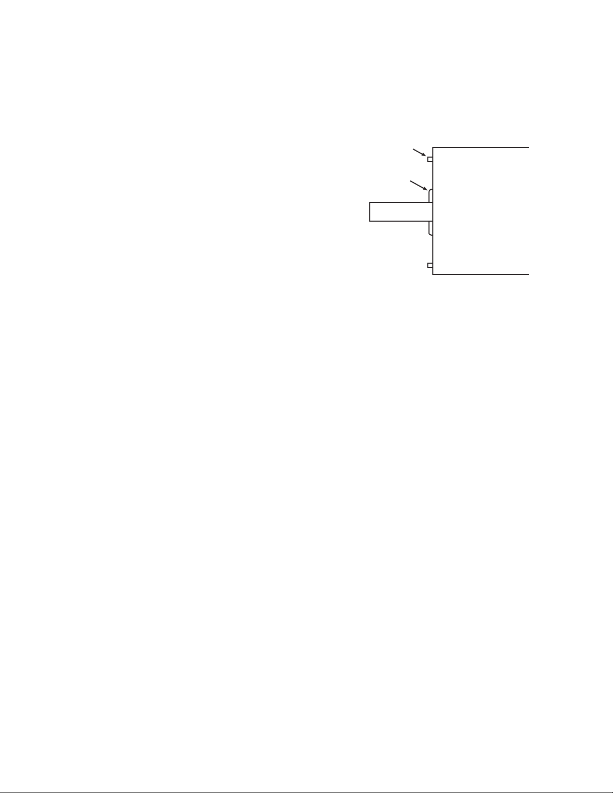
C-face mounting
If this boss extends
beyond the C-face
surface use the
spacer.
Do not use spacer
if boss is below the
C-face surface.
1. Simply slide the screwdriver through the
window and press the armature toward its mating friction surface.
2. Rotate the output of the unit. The rotor and the
window should stay in place when you do this.
Only the armatures will move. Rotating the
rotor will move the window.
3. Repeat steps 1 & 2 to ensure that the airgap
between armature and its mating friction surface is about 1/32” and that the armature is
kept square. (If the armature is cocked, it may
engage on one rim, giving the appearance of
engagement but failing to provide full torque.)
3. When using the EM-180-20 a possible interference may exist between the splined armature hub and some motors. (See Figure 10) A
spacer ring is provided with the EM-180
mounting accessory to provide the necessary
running clearance.
Section D: Mounting the Brake to a Motor
The brake module (20) can be mounted directly
to a motor.
1. Insert a key in the motor shaft keyway. Prick
punch the end of the (EM-50 and EM-100)
motor shaft keyway to prevent the key from
sliding out.
2. A set collar is provided in the EM-180 and
EM-210 mounting accessory to prevent the
key from sliding out. Slide the set collar up
against the motor bearing and tighten the
setscrew securely. (Figure 9)
Figure 10
Place the spacer ring between the brake
module housing and the C-face of the motor
when bolting the two units together.
4. Align the motor shaft and key with the mating
shaft hole and key slot in the brake module.
5. Secure brake module to the motor C-face with
the four (4) long 3/8-inch hex head capscrews.
Section E: Installing the Motor Mount (M)
A Motor Mount (M) can be installed to the brake
or output clutch module to provide a foot mounting for the complete assembly of module and
motor.
1. Remove the two (2) long hex head bolts from
the side of the module toward the ventilation
holes.
Warner Electric • 800-825-9050 P-213 • 819-0303
6
2. Mount the module on the Motor Mount so that
the base of the Motor Mount is underneath
the modules and motor. (See Figure 11) A pilot
diameter on the module mates with a pilot
diameter on the Motor Mount.
Figure 9

Figure 11
3. Secure the Motor Mount in place with two (2)
longer mounting bolts and the two shorter
bolts all provided in the kit.
Section F: Installing the Base Mount
Section G: Mounting to a Reducer
The output side of a brake (20) or output clutch
(40) module may be mounted directly to a reducer.
1. Align the output shaft and key of the modules
with the corresponding shaft hole and keyway
of the reducer. Slide the assembly together,
matching the pilot diameter on the module with
a pilot diameter on the reducer. (Figure 13)
Modules 20-30 and 30-40 can be base-mounted.
1. Mount the modules so that the base is located
below the ventilation holes. A pilot diameter
on the end of each module mates with pilot
diameters on the base.
2. Secure the base to the modules with the four
(4) bolts provided. (Figure 12)
Figure 12
Figure 13
2. Bolt the module to the reducer flange. The
four (4) bolts required (3/8 - 16 UNC-2A) are
normally furnished with the reducer.
Section H: Electrical Connections
The conduit connection hole in the motor clutch
module (10), brake (20), and input clutch (30) are
threaded for standard conduit connectors. The
wiring diagram, included with each Warner Electric
control shows the proper electrical connections
that must be made. (Control Service Manual P-239
includes complete information on all standard
control power supplies.)
For clutch/brake combinations, connect the red
wire from one module and the black wire from the
other module to the same terminal of the DC supply. With most basic Warner Electric controls, one
terminal is normally used for two connections –
one from the brake and one from the clutch.
For wiring of clutches, brakes, and clutch/brake
combinations consult manual P-239 for the wiring
diagram of the control being used. These
clutch/brakes are not polarity sensitive.
Warner Electric • 800-825-9050 P-213 • 819-0303
7
 Loading...