


Tension Control System
XCTRL & XCTRL-2DRV
Installation and Operation Manual
P-2097-WE-A4
I.\ |
INTRODUCTION....................................................................................................................................................................... |
4 |
|
II.\ |
GENERAL INFORMATION....................................................................................................................................................... |
4 |
|
III.\ |
XCTRL BLOCK DIAGRAM....................................................................................................................................................... |
5 |
|
IV.\ |
HARDWARE PIN OUT.............................................................................................................................................................. |
6 |
|
V.\ |
XCTRL-2DRV............................................................................................................................................................................ |
7 |
|
VI.\ SYSTEM WIRING AND SETTING............................................................................................................................................ |
7 |
||
1.\ |
TYPICAL WIRING................................................................................................................................................................. |
7 |
|
2.\ |
OPERATION PRINCIPLE....................................................................................................................................................... |
7 |
|
3.\ |
DANCER ARM WIRING......................................................................................................................................................... |
8 |
|
4.\ |
LOAD CELL WIRING............................................................................................................................................................. |
8 |
|
5.\ |
POWER SUPPLY WIRING..................................................................................................................................................... |
9 |
|
6.\ WIRING WITH AN X2DRV..................................................................................................................................................... |
9 |
||
7.\ (OPTIONAL) AUXILIARY ANALOG SENSOR WIRING.......................................................................................................... |
9 |
||
8.\ |
(OPTIONAL) MANUAL CALIBRATION................................................................................................................................... |
10 |
|
9.\ (OPTIONAL) TOUCH SCREEN INSTALLATION AND SETTING............................................................................................ |
11 |
||
|
a.\ WIRING THE XPRO INTERFACE TO THE XCTRL............................................................................................................ |
11 |
|
VII.\ SOFTWARE INSTALLATION & SETTING................................................................................................................................. |
12 |
||
1.\ |
SOFTWARE DOWNLOADING............................................................................................................................................... |
12 |
|
2.\ |
SOFTWARE INSTALLATION.................................................................................................................................................. |
12 |
|
3.\ |
COMPUTER WIRING............................................................................................................................................................ |
12 |
|
VIII.\XCTRL CONFIGURATION........................................................................................................................................................ |
13 |
||
1.\ XCTRL CONFIGURATOR LANGUAGE SELECTION............................................................................................................. |
13 |
||
2.\ |
PARTITION SETTING............................................................................................................................................................ |
13 |
|
|
|
• READ/WRITE PARTITION................................................................................................................................................... |
14 |
|
|
• IMPORT/EXPORT PARTITION............................................................................................................................................ |
15 |
|
|
• FACTORY DEFAULT........................................................................................................................................................... |
16 |
|
|
• SD CARD............................................................................................................................................................................ |
17 |
3.\ INPUT SELECTION AND SETTING....................................................................................................................................... |
18 |
||
|
|
• CELLS / DANCER INPUT................................................................................................................................................... |
18 |
|
|
• CALIBRATION.................................................................................................................................................................... |
18 |
|
|
• RANGE DEFINITION........................................................................................................................................................... |
19 |
4.\ |
PID SETTING......................................................................................................................................................................... |
20 |
|
|
|
• SELECT THE INPUT........................................................................................................................................................... |
20 |
|
|
• SET UP THE SETPOINT..................................................................................................................................................... |
20 |
|
|
• ENTER THE GAINS............................................................................................................................................................ |
20 |
|
|
• COMPENSATION............................................................................................................................................................... |
20 |
|
|
• STOP INTEGRAL (STPINT)................................................................................................................................................. |
21 |
5.\ SPLICE SELECTION AND HOLD OUT CONFIGURATION.................................................................................................... |
22 |
||
|
|
• SPLICE SELECTION........................................................................................................................................................... |
23 |
|
|
• HOLD OUT / MAX OUT...................................................................................................................................................... |
24 |
6.\ |
INPUT/OUTPUT CONFIGURATION...................................................................................................................................... |
25 |
|
|
|
• DIGITAL INPUT SETTINGS................................................................................................................................................. |
25 |
|
|
• SYNC INPUT ACTIVATION................................................................................................................................................. |
26 |
|
|
• DIGITAL OUTPUT (ERRS1, ERRS2) SETTINGS................................................................................................................. |
26 |
|
|
• THE ANALOG OUTPUT (OUT1, OUT2) SETTINGS............................................................................................................ |
26 |
2 Warner Electric • +33 (0) 2 41 21 24 24 |
P-2097-WE-A4 |
7.\ |
AUXILIARY SENSOR SETTING (ANA INPUT)....................................................................................................................... |
26 |
|
• AUXILIARY ANALOG INPUT TYPE.................................................................................................................................... |
27 |
|
• AUXILIARY SENSOR CALIBRATION.................................................................................................................................. |
27 |
8.\ |
OPEN LOOP CONFIGURATION............................................................................................................................................ |
28 |
|
• LINEAR CURVE.................................................................................................................................................................. |
28 |
|
• X FACTOR.......................................................................................................................................................................... |
28 |
9.\ |
DIAGNOSTIC TOOLS............................................................................................................................................................ |
29 |
|
• REAL TIME INFORMATION’ WINDOW............................................................................................................................... |
30 |
|
• INPUT/OUTPUT’ WINDOW................................................................................................................................................ |
31 |
10.\ XCTRL FIRMWARE UPDATE................................................................................................................................................ |
32 |
|
IX.\ XCTRL FAMILY PART LIST...................................................................................................................................................... |
33 |
|
Warner Electric • +33 (0) 2 41 21 24 24 |
P-2097-WE-A4 3 |
I.\ INTRODUCTION:
This control is a solid state electronic control that receives signal from a Dancer pivot point sensor or 2 Load cells and transmits internally the appropriate signals to the brake power driver to regulate a stable tension.
It integrates 2 separate Digital PID controllers and 2 separate Open Loop control. Based on a double board architecture, it can integrate a Driver board to control our electromagnetic brakes range. In that particular case, all communication, Input/Output and power signal of the driver board will be made thru an internal connector.
All parameters could be saved to an integrated memory and to an SD Card, but can also be uploaded or downloaded thanks to its external communication bus (USB).
In case of Load Cell application, when the setpoint needs to be modified, an optional handset is available.
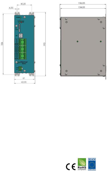
Figure 1: XCTRL Housing Dimensions
II.\ GENERAL INFORMATION
Control chassis should be kept clear of all areas where foreign material, dust, grease, or all might affect the operation of the control. Installation must be made in accordance with the instructions found in this manual. Failure to do so may damage the Controller. Throughout this manual the PID board will be called the XCTRL board and the Driver board will be called the X2DRV board.
Ratings
Main supply Voltage (V) |
24V DC +/- 5% |
Output |
0-10V and/or 4-20mA |
|
|
Operating T°C |
0°C to 50°C no condensation |
|
|
Compliance |
|
|
|
4 Warner Electric • +33 (0) 2 41 21 24 24 |
P-2097-WE-A4 |

III.\XCTRL Block Diagram
Figure 2: XCTRL Block Diagram
Warner Electric • +33 (0) 2 41 21 24 24 |
P-2097-WE-A4 5 |

IV.\ Hardware Pin Out
|
|
|
|
|
1 |
SD Card |
External interface |
Parameters Savings. Possibility to save up to 8 partitions. |
|
|
|
|
|
|
2 |
USB |
External interface |
Use to setup the controller (Input/Output, PID, splice parameters) and to up- |
|
load and download all parameters to a setup partition. |
||||
|
|
|
||
|
|
|
|
|
3 |
A |
Digital IN |
Splice selection inputs. Depending on the A, B, C bit state, select a configu- |
|
|
|
|
ration of OUT1, OUT2, between a logical menu of 11 possibilities and select |
|
4 |
B |
Digital IN |
||
PID1&2 compensation input |
||||
|
|
|
||
5 |
C |
Digital IN |
NPN, PNP input type Selectable. |
|
|
|
|
|
|
|
|
|
Logical input which activate the changes of the A, B, C inputs. Depending on |
|
6 |
Sync |
Digital IN |
logical setting, it could be activate on edge or on state. |
|
|
|
|
NPN, PNP input type Selectable. |
|
7 |
ErrS1 |
Digital Out |
Error signal output to inform that Sensor1/Cell1 is out of range. Working range |
|
can be programmed in %, Kg, Nm… 0-24VDC |
||||
|
|
|
||
|
|
|
|
|
|
|
|
|
|
8 |
P1 |
Digital IN |
Parameters Partition signal input. Depending on the P1, P2, P3 bit state, it |
|
|
|
|
offers a selection to all parameters tables used to setup all Input/Output, PID |
|
9 |
P2 |
Digital IN |
||
and Open loop controllers |
||||
|
|
|
||
10 |
P3 |
Digital IN |
NPN, PNP input type Selectable. |
|
|
|
|
|
|
11 |
Stplnt |
Digital IN |
Stop or reset the integral calculation of the PID |
|
NPN, PNP input type Selectable. |
||||
|
|
|
||
|
|
|
|
|
12 |
ErrS2 |
Digital Out |
Error signal output to inform that Sensor2/Cell2 is out of range. Working range |
|
can be programmed in %, Kg, Nm… 0-24VDC |
||||
|
|
|
||
|
|
|
|
|
|
|
|
|
|
13 |
24V |
Power supply |
Auxiliary 24VDC Power supply, 100mA |
|
OUT |
||||
|
|
|
||
14 |
Out1 |
Analog Output |
Analog Output of PID1 or Open Loop 1 out depending on ABC selection. |
|
Selectable: 0/+10V DC or 4/20mA. |
||||
|
|
|
||
|
|
|
|
|
15 |
Gnd |
Ground |
|
|
|
|
|
|
|
|
|
|
Auxiliary Sensor Input: usually used to compensate the PID Gain versus the |
|
16 |
Ana1 |
Analog Input |
roll diameter |
|
|
|
|
Selectable: 0/+10V DC or 4/20mA. |
|
|
|
|
|
|
17 |
Gnd |
Ground |
|
|
|
|
|
|
|
|
|
|
|
|
18 |
24V |
Power supply |
24VDC Power supply, 100 mA |
|
OUT |
||||
|
|
|
||
|
|
|
|
|
19 |
Out2 |
Analog Output |
Analog Output of PID2 or OL2 out depending on ABC selection. |
|
Selectable: 0/+10V DC or 4/20mA. |
||||
|
|
|
||
20 |
Gnd |
Ground |
|
|
|
|
|
|
|
|
|
|
Auxiliary Sensor Input: usually used to compensate the PID Gain versus the |
|
21 |
Ana2 |
Analog Input |
roll diameter |
|
|
|
|
Selectable: 0/+10V DC or 4/20mA. |
|
|
|
|
|
|
22 |
Gnd |
Ground |
|
|
|
|
|
|
|
|
|
|
|
|
23 |
Ex1+ |
Power Out |
Sensor power supply & Load Cell excitation |
|
Selectable 0-10Vdc or 0-15Vdc, 100mA |
||||
|
|
|
||
24 |
Ex1- |
Power Out |
|
|
|
|
|
|
|
25 |
C1+ |
Differential Analog |
Load Cell and/or Dancer Arm sensor input |
|
0-10Vdc, 0-40mVdc |
||||
|
|
|||
|
|
Input |
|
|
26 |
C1- |
|
||
|
|
|||
|
|
|
|
|
27 |
Shld |
Shielding |
Load Cell or Sensor shielding |
|
|
|
|
|
|
|
|
|
|
|
28 |
Ex2+ |
Power Out |
Sensor power supply & Load Cell excitation |
|
29 |
Ex2- |
Power Out |
Selectable 0-10Vdc or 0-15Vdc, 100mA |
|
|
||||
|
|
|
|
|
30 |
C2+ |
Differential Analog |
Load Cell and/or Dancer Arm sensor input |
|
31 |
C2- |
Input |
0-10V DC, 0-40mVdc |
|
|
||||
|
|
|||
|
|
|
|
|
32 |
Shld |
Shielding |
Load Cell or Sensor shielding |
|
|
|
|
|
This installation and Operating Manual has been arranged for the systematic installation and start-up of your Tension Control System. Please check off each step before proceeding to the next step.
6 Warner Electric • +33 (0) 2 41 21 24 24 |
P-2097-WE-A4 |
V.\ XCTRL-2DRV
When working with the XCTRL-2DRV, no wiring between the XCTRL and the X2DRV control board are needed.
In fact, the power supply as well as the connections between the analog outputs (OUT1 & OUT2) of the XCTRL and the analog inputs of the X2DRV (InBK1 & InBK2) control boards are internally made.
If more information is needed on the standalone X2DRV control, please refer to the ‘X2DRV Installation and Operation Manual’
VI.\System wiring and setting
WARNING: Contact with electrical voltages present in the controller covered in this manual can cause injury. To avoid these consequences, make sure all power is off during installation.
These wiring precautions will help you properly install and wire a trouble-free system.
1.\ Use proper gauge wire for all pin:
\- Data input: 0,5mm² (20 AWG) or 0,75mm² (18 AWG)
\- Brakes wires: 0,75mm² (18 AWG) or 1mm² (17 AWG) 2.\ Shielded cable is recommended for all connections
3.\ Do not use this controller for purposes other than those intended. Such use could damage the controller
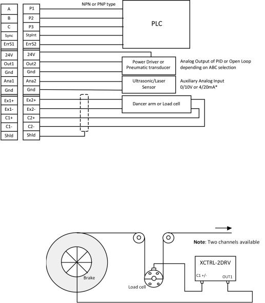
1.\ Typical Wiring
Figure 3: XCTRL Typical Wiring
2.\ Operation Principle
The closed Loop controls are usually made with using two types of sensors: the dancer arm and the load cell. The XCTRL controller supports both. These two sensors provide a voltage signal proportional to the web tension. This signal is interpreted and the web tension is adjusted accordingly by braking thru one of the integrated PID controller.
Load Cell Applicaiton:
Figure 4: Load Cell Application
Warner Electric • +33 (0) 2 41 21 24 24 |
P-2097-WE-A4 7 |
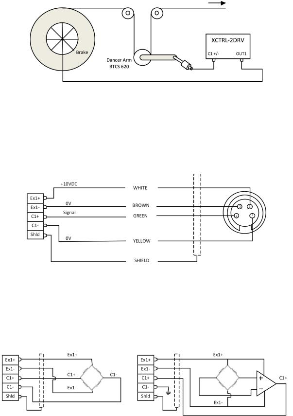
Dancer Arm Application:
Figure 5: Dancer Arm Application
3.\ Dancer Arm Wiring
Wire Dancer Arm BTCS605-E2 or BTCS 620 to the controller as describe below, use channel 1 or 2. For all generalist wiring refer to figure 2 above. Please refer to the paragraph Input Selection and Setting to setup the XCTRL accordingly.
Figure 6: Dancer Arm Wiring
4.\ Load Cell Wiring
Wire Load Cell (not amplified or amplified) to the controller as describe below, use channel 1 and/or 2. For all generalist wiring refer to figure 2 above.
Figure 7: Not Amplified Load Cell Wiring |
Figure 8: Amplified Load Cell Wiring |
Note: For all load cell wiring please refer to the corresponding Datasheet
8 Warner Electric • +33 (0) 2 41 21 24 24 |
P-2097-WE-A4 |
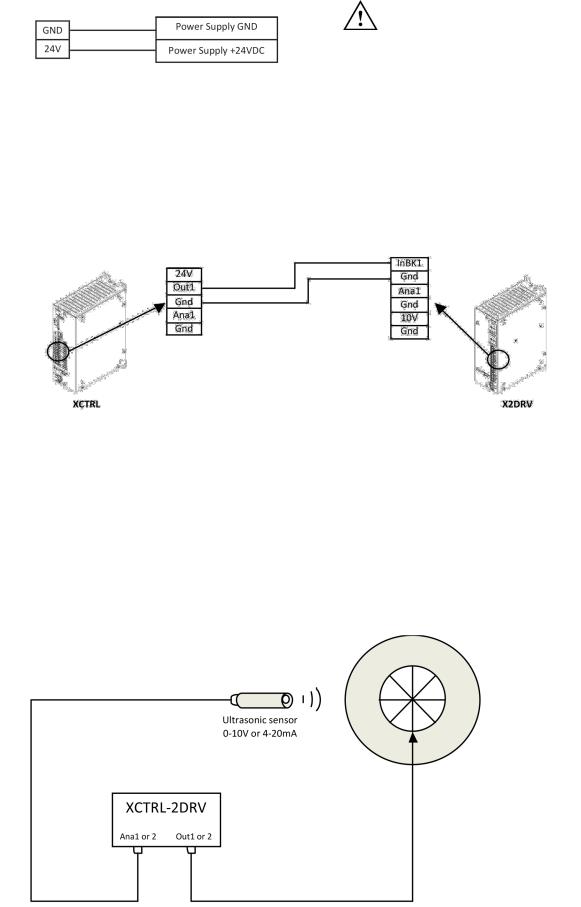
5.\ Power Supply Wiring
Wire 24VDC input power to pin 24V as shown below:
\ CAUTION: Improperly setting the 24VDC can damage the power supply and/or the controller
Figure 9: Power supply wiring
6.\ Wiring with an X2DRV
If you don’t have an XCTRL-2DRV and you want to get a closed loop control, the XCTRL can be associated with the X2DRV. For all detail about the driver refer to the X2DRV Installation & Operation manual. The XCTRL output and the X2DRV Input are selectable (0-10V or 4-20mA). To wire the XCTRL with an X2DRV follow the procedure below:
Note: 2 Channels available (Out1, Out2, InBK1, InBK2)
Figure 10: XCTRL & X2DRV wiring
Note: When the XCTRL is associated with an X2DRV (XCTRL-2DRV), power supply, input and communication are made by an internal connector. No connection extra connection between the controller and the driver is needed.
7.\ (Optional) Auxiliary analog sensor wiring
Two auxiliary sensor inputs are available. They can both be programmed in 0-10Vdc or 4-20mA type Inputs. They can also be used with the PID or the Open Loop Controllers input, refer to section 4.d and/or 4.h paragraph II/ Software Installation and Setting. The most popular use is to have them coupled to a roll diameter sensor in order to compensate the PID Gain during unwinding
Figure 11: PID Gain Compensation in linear compensation mode
Warner Electric • +33 (0) 2 41 21 24 24 |
P-2097-WE-A4 9 |
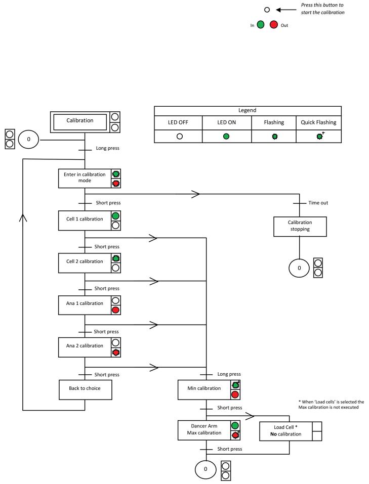
8.\ (Optional) Manual Calibration
The manual calibration of the XCTRL controller allows you to calibrate the sensor Input (Cell1/Cell2) and the auxiliary sensor input (Ana1/Ana2) without the XCTRL Configurator application. The calibrated values will be then applied to the partition selected by P1, P2, P3 inputs.
Use the button above the green LED to start the calibration and follow the procedure. A long press corresponds to 5s and a time out is equal to 10s.
Procedure:
10 Warner Electric • +33 (0) 2 41 21 24 24 |
P-2097-WE-A4 |
5.\ (Optional) Touch Screen Installation and Setting
The optional touch Screen (Xpro) allows you to modify the setpoint easily. It is generally necessary when Load cells are used to change the tension while running.
It’s also offering to display some curves and values in real time.
If customer wants to use its own screen, a set of control code is described in the application note AN_ XPRO_SetOfCommand.pdf.
\
\ |
\ |
a. Wiring the XPro Interface to the XCTRL |
Warner Electric • +33 (0) 2 41 21 24 24 |
P-2097-WE-A4 11 |
 Loading...