


CBC-801 Series Clutch/Brake Controls
P-239-17 819-0476
Installation and Operation Manual
Introduction
The Warner Electric CBC-801 series is a family of plug-in clutch/brake controls designed for
operation of all Warner Electric 90 volt DC clutches and brakes. They should not, however, be used to directly power Warner Electric permanent magnet failsafe brakes as these products require an adjustable current or voltage supply for optimum release. The CBC-801 series controls are available in two models:
CBC-801-1 |
120 VAC input |
CBC-801-2 |
220/240 VAC input |
These controls indicate when the brake and clutch are energized with red and green LED's respectively. An internal fuse protects the control from damage in an overload condition. The CBC-801 series controls are UL Listed when used with Warner Electric's octal socket, part no. 6001-101-001, or DIN rail mount octal socket, part no. 6001-101-002 (each purchased separately).
Reorder Information
|
Model |
Part Number |
|
|
|
CBC-801-1 |
6001-448-004 |
|
CBC-801-2 |
6001-448-006 |
|
Octal Socket |
6001-101-001 |
|
DIN Rail Mount Octal Socket |
6001-101-002 |
|
Installation
 To avoid injury (or even death), always make certain all power is off before attempting to install this control or any electrical equipment.
Specifications
Input
CBC-801-1: 120 VAC, 50/60 Hz, 1 phase, 150 VA max. CBC-801-2: 220/240 VAC, 50/60 Hz, 1 phase, 150 VA max.
Output
CBC-801-1: 90 VDC full-wave rectified nominal, 1.25 amps max.
CBC-801-2: 90 VDC half-wave rectified nominal, 1.25 amps max.
Fusing (under cover)
CBC-801-1,-2: 5x20mm, 1.6 amp, 250V fast-blo Switching (external to control, supplied by customer )
CBC-801-1: Rated 120 VAC, 10 amp (inductive) CBC-801-2: Rated 240 VAC, 10 amp (inductive)
Ambient Temperature
-20° to +122°F (-29° to 50°C)
Cycle Rate:
Consult the Application Engineering section of Warner Electric's Basic Design Clutches/Brakes Catalog, P-1264-WE, for the capabilities of your application.
1.Connect the two wires from the brake (or clutch) to terminals 2 and 8 of the socket.
2.Connect the two wires from the clutch (or brake) to terminals 3 and 6 of the socket (pins 2 & 6 are connected internally).
3.Connect the switch (provided by the customer) between terminals 7, 8, and 3 as shown in the Connection diagram.
4.Connect the AC input to terminals 1 and 5.
Note: For 120 VAC (CBC-801-1), the "HOT " line must be connected to terminal 1. This line measures 120 VAC to conduit ground.
 This is a floating type power supply and is not referenced to AC ground. Under no circumstances should any of the
output wire leads be connected to earth or chassis ground as the unit will be destroyed.
Connection
|
|
|
|
|
|
|
|
|
|
|
|
|
|
|
|
|
|
|
|
N e u t r a l |
|
|
|
|
90 Volt Clutch |
|
|
|
|
|
|
||||||||
|
|
|
|
|
|
|
|
|
|
|
|
|
|
|
|
|
|||
|
|
|
|
|
|
|
|
|
|
|
|
|
|
|
|
|
|
|
|
CBC-801-1: |
6 |
|
5 |
4 |
3 |
|
|||||||||||||
(-) |
|
|
|
|
|
|
|
|
|
|
|
|
|
||||||
120 VAC |
|
|
|
|
|
|
|
|
|
|
|
|
|
||||||
|
|
|
|
Octal Socket |
|
|
|
|
|
|
|||||||||
|
|
|
|
|
(+) |
|
|
(-) |
|
||||||||||
CBC-801-2: |
|
|
|
|
|
|
|
|
|||||||||||
|
|
|
|
|
|
|
|
|
2 |
|
|||||||||
220/240 VAC |
7 |
|
8 |
1 |
|
||||||||||||||
Hot |
|
|
|
|
|
|
|
|
|
|
|
|
|
|
|
|
|
|
|
|
|
|
|
|
|
|
|
|
|
|
|
|
|
|
|
|
|
||
|
|
|
|
|
Stop |
• |
|
|
|
|
|
|
|
|
|||||
|
|
|
|
|
|
|
|
|
|
|
|
|
|
|
|||||
|
|
|
Switch |
|
|
90 Volt Brake |
|
||||||||||||
|
|
|
|
|
• |
|
|||||||||||||
|
(furnished |
|
|
|
• |
|
|
|
|
|
|
|
|
||||||
|
|
|
by user) |
|
|
Start |
|
|
|
|
|
|
|
|
|||||
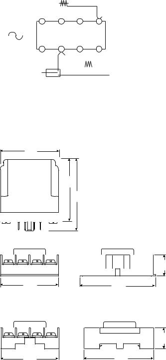
Dimensions
1.95"
(49.5)
1.7"
(43.2)
2.4"
(61)
1.57"
(39.9)
1.57"
(39.9)
.70"
(17.8)
2.39"
(60.7)
.71"
(18)
2.40"
(61)
2 Warner Electric • 800-234-3369 |
P-239-17 • 819-0476 |
 Loading...