

Page 1
Operating Manual
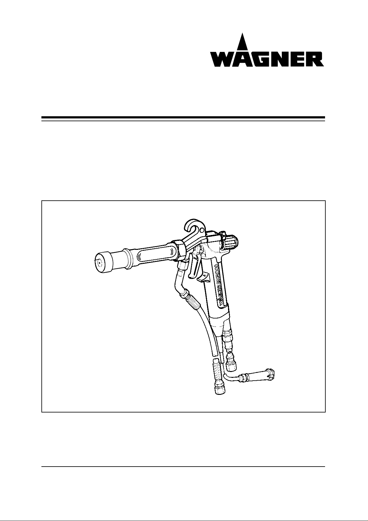
Electrostatic AirCoat Spraygun,
with flat or round jet tips
GM 2000 EACR - EN
GM 2000 EACF - EN
0179 887 GBEdition 03/98
Page 2

Page 3

GM 2000 EAC - EN
CONTENTS
Paragraph Chapter.Page
1 INTRODUCTION 1.1
1.1 Using the manual 1.1
1.2 SAFETY REGULATIONS 1.2
1.3 PTB Conformity certification 1.4
1.4 Product liability and guarantee 1.5
1.5 CE conformity 1.6
2 DESCRIPTION 2.1
2.1 Scope of supply 2.1
2.2 Technical data 2.1
2.3 Functional description 2.1
2.3.1 Function of the gun 2.1
2.3.2 AirCoat round jet process 2.3
2.3.3 AirCoat flat jet process 2.3
2.3.4 Electrostatic effect 2.4
2.4 What kind of spraying material can be applied? 2.4
3 PREPARATION BEFORE STARTING WORK 3.1
3.1 Preparation of paint 3.1
3.2 Earthing 3.1
4 STARTING WORK, AND HANDLING 4.1
4.1 Preparation 4.1
4.2 General rules for handling the spray gun 4.1
4.3 Starting-up for AirCoat spraying 4.1
4.4 Cleaning of clogged round jet tips 4.2
4.5 Exchange of AirCoat round jet tip insert. (EAC round) 4.2
4.6 Changing from AirCoat round jet to AirCoat flat jet 4.2
4.7 Replacing AirCoat flat jet tips 4.3
4.8 Cleaning of AirCoat flat jet tips 4.3
4.9 Clogging of AirCoat flat jet tips 4.3
5 MAINTENANCE 5.1
5.1 Decommissioning and cleaning 5.1
5.2 Dissassembly of AirCoat nozzle body 5.2
5.3 Exchange or cleaning of filters 5.2
5.4 Adjustment of the valve rod seal 5.3
5.5 Exchange of complete valve rod, or of valve rod seals 5.3
5.6 Exchange of paint channel 5.4
6 TROUBLE SHOOTING AND SOLUTIONS 6.1
0.1
Page 4

GM 2000 EAC - EN
CONTENTS
Paragraph Chapter.Page
7 ACCESSORIES 7.1
7.1 Round jet tip inserts 7.1
7.2 AirCoat flat tips 7.2
7.3 Filter (standard) 7.3
7.4 Long filter housing and filters 7.3
7.5 Hoses and fittings 7.3
7.6 Special tools 7.3
8 SPARE PARTS CATALOGUE 8.1
8.1 How to order spare parts? 8.1
8.2 Special marks in spare parts lists 8.1
8.3 Spare parts list and drawing 8.2
0.2
Page 5

1. INTRODUCTION
This operating manual contains information and instruction for the operation, repair
and maintenance of the spray gun.
This equipment can be dangerous if it is not operated in accordance with this Operating manual!
Compliance with these instructions constitutes an integral component of the guarantee
agreement.
1.1 Using the manual
"Caution"
This heading is used wherever non-compliance with operating instructions, working instructions, specified working sequences etc. may result in injury or accident.
"Attention"
GM 2000 EAC - EN
This heading is used wherever non-compliance with operating instructions, working instructions, specified working sequences etc. may result in damage to the equipment.
"Note"
This heading is used to draw attention to a particular passage in the text.
Subject to change without notice Printed in Switzerland
1.1
Page 6
GM 2000 EAC - EN
1.2 SAFETY REGULATIONS
The safety requirements for electrostatic hand spraying equipement are laid
down in the following documents: (Germany)
1) ZH 1/250 Electrostatic enamelling with hand-held spraying equipment
(Published by C. Heymanns-Verlag, Cologne)
2) ZH 1/406 Guidelines for jet stream equipment (spraying devices)
(Published by C. Heymanns-Verlag, Cologne)
3) EX-RL/ZH 1/10 Explosion protection guidelines - spraying equipment
(Published by C. Heymanns-Verlag, Cologne)
4) VBG 23 Working with coating materials
(Published by C. Heymanns-Verlag, Cologne)
5) DIN-VDE 0165 Installation of electrical equipment in a potentially explosive
atmosphere
6) EN 50050/DIN- Electrostatic hand spraying equipment
VDE 0745 Part 100
7) EN 50053/DIN- Selection, installation and use of electrostatic spraying
VDE 0745 Part 101 equipment - electrostatic hand spraying equipment for combu-
(Published by VDE-Verlag, Berlin)
stible liquid spray media
(Published by VDE-Verlag, Berlin)
(Published by VDE-Verlag,Berlin)
Caution
The following points should receive special attention for the safe use of the
electrostatic spraying equipment:
1.2.1 Caution! Danger of injury by injection
The pressure should be released from the spray gun during breaks in
work or while assembling and dismantling the nozzle. It should be
secured, the control unit switched off, and the plug pulled out. Never
point the gun at yourself or any other person, the spray jet can cause
injury by injection.
Never put your finger or hand in the spray jet.
In case of injury to skin by paint or cleaning agents consult a doctor
immediately. Inform the doctor of the type of paint or cleaning agent
used.
1.2.2 Cleaning
The gun must be switched off when being cleaned and should never be
sprayed in "closed" containers (formation of a gas air/mixture which can
explode). The containers must be earthed.
1.2.3 Safety
Spraying can only be carried out safely, both for people and the environment, if
it is done in a spray booth or in front of a spraying wall with sufficient ventilation
(removal by suction).
In order to avoid occupational illness the safety regulations laid down by the
manufacturer of the paint or cleaning agent used must be adhered to during
preparation and application of the paint and while cleaning the equipment. In
particular, protective clothing, gloves, skin protection cream and breathing
equipment must be used to protect the skin and respiratory tracts.
1.2
Page 7

GM 2000 EAC - EN
1.2.4 Protective breathing masks
Although the E-Static AirCoat spraying procedure produces very little mist, it is
not completely mist free. There are, in fact, few paint particles to be found in
the air. Nevertheless, the operator must use a protective breathing mask, (see
respiratory equipment instruction sheet ZH 1/134 and VGB 23 from the
professional trade association) during spraying operations.
1.2.5 The spray gun and the high pressure hoses between the pump and the
spray gun must be of a sufficient quality for the pressure produced by the
pump.
A permanent marking on the high pressure hoses must indicate the maximum
permitted working pressure, the manufacturer and date of production.
Furthermore, it must be of a suitable quality so that the electric resistance
between the pump connection and the spray gun is less than 1 megaohm.
1.2.6 Earthing
Depending on the electrostatic charge and the flow speed of the spray an
electrostatic charge may, in certain cases, occur on the equipment. This could
cause a spark or flame on discharging. In order to avoid this the equipment
must always be earthed.
There must be a conductive connection (potential equalisation cable) between
the material container and the equipment.
All persons within the working area must wear shoes with electricallyconductive
soles (e.g. shoes with leather soles). Gloves must also be conductive, because
the operator is earthed through the handle of the spraygun. The floor of the
working area must be conductive, in accordance with VDE 0745, part 1,
paragraph 35: measurements according to DIN 51953.
1.2.7 Extraction systems
Paint mist extraction systems must be fitted on site according to the local
regulations.
1.2.8 Accessories and spare parts
The manufacturer's guarantee and product liability are only valid if original
Wagner accessories are used.
1.2.9 Safety information on harmless electrostatic discharges
If the plastic parts of the spray gun are touched with the hand this can result in
a harmless discharging (so-called brush discharge). The same occurs when
you electrostatically charge yourself by walking on a synthetic carpet and then
touch a metallic door handle, thus discharging the electrostatic charge. The
charge on the plastic parts is caused by the high-voltage field of the gun. The
discharging is completely safe for people and is not able to cause any ignition.
A corona glow may occur at the electrode end of the gun when it is in use (only
visible under dark conditions). A corona discharge can occur if the electrode
(spray gun) comes within a distance of 4 - 10 mm from the object being sprayed. The corona glow does not cause any ignition hazard.
1.3
Page 8
GM 2000 EAC - EN
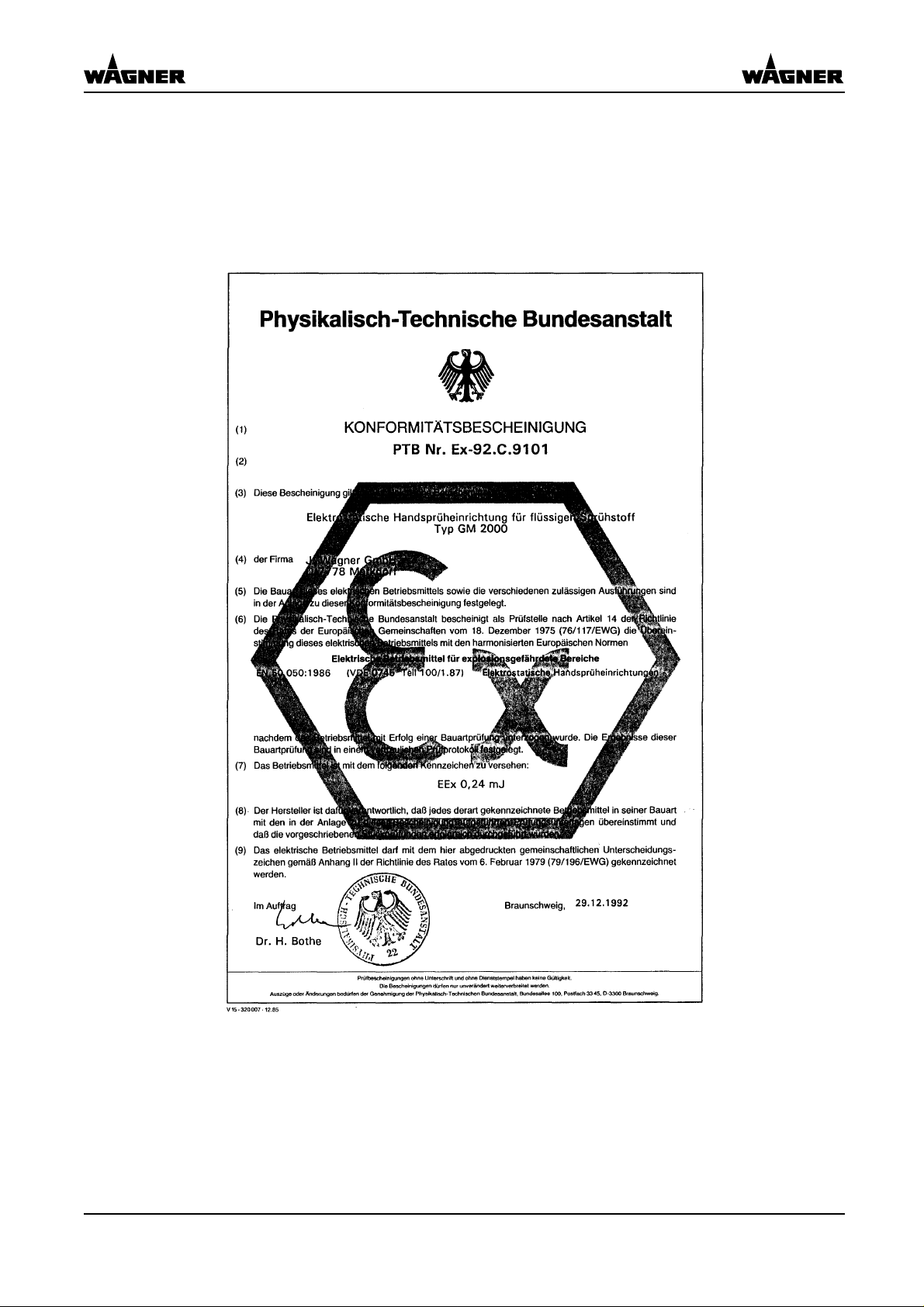
1.3 PTB Conformity certification
1.4
Page 9
GM 2000 EAC - EN
1.4 Product liability and guarantee
Important notes on product liability
As a result of an EC regulation being effective as from January 1, 1990, the manu-
facturer shall only be liable for his product if all parts come from him or are released by him, and if the devices are properly mounted and operated.
If the user applies outside accessories and spare parts, the manufacturer's liability
can fully or partially be inapplicable.
Only the usage of original WAGNER accessories and spare parts guarantees
that all safety regulations are observed.
Warranty
12 months / 6 months for multi-shift operation
This equipment is covered by the following manufacturing warranty:
All parts which prove unusable or the use of which is seriously impaired within
12 months or 6 months of receipt by the purchaser due to circumstances predating
receipt, such as faulty design, defective materials or poor workmanship, shall be
repaired or replaced at our discretion and free of charge.
No liability is assumed for damage attributable to the following factors:
Inappropriate or incorrect use, faulty installation or start-up by the purchaser or third
parties, natural wear and tear, as well as wear parts (marked * in the list of spare
parts), incorrect handling or maintenance.
The equipment must be checked immediately upon receipt. Obvious defects must be
reported to the supplier or to us in writing within 14 days of receipt in order to avoid
losing the right of complaint.
We reserve the right to assign warranty performances to a contractual partner.
Warranty performances shall only be rendered if the purchaser returns the warranty
card bearing the date of sale and seller's signature together with the equipment. The
repair costs will be charged to the purchaser if it is found that the warranty does not
apply.
1.5
Page 10

1.5 CE Conformity
1.5.1 Short explanation
CE = Communauté Européenne:
Products identified with the CE mark have been manufactured and checked according
to EU guidelines. This means that, in terms of materials used, manufacturing process
and operation, they are in accordance with the EU safety and health requirements and
therefore the EU regulations and standards. The regulations and standards applying to
a particular product can be found in the CE Certificate of Conformity. This is enclosed
with the product or can be requested from the manufacturer. The CE identification
has been compulsory in Europe since 1st January 1995, and only products bearing
CE identification may be released into circulation.
EMC test:
The electromagnetic compatibility test forms an integral part of the CE conformity.
EMC tested products are built such that their interference radiation does not influence
other devices within the stipulated limits (noise on the radio, etc.). The EMC standard
differentiates between use in domestic, business and commercial or industrial areas.
Moreover, if required for comfort or safety reasons, products can be EMC tested for
their interference immunity. This means they are protected from the influence of
external interference.
GM 2000 EAC - EN
1.5.2 EC Certificate of Conformity
The certificate with the Part No.:
0179 780
is enclosed with this product. This can be reordered from your WAGNER representative, quoting the product and serial number.
1.6
Page 11
GM 2000 EAC - EN
2. DESCRIPTION
2.1 Scope of supply
Part No. Quantity Description
0179 018 1 Electrostatic AirCoat spray gun GM 2000 EAC R, with
round jet tip R 15 .
or
0179 019 1 Electrostatic Air coat spray gun GM 2000 EAC F, without
flat jet tip.
The standard equipment includes: GM 2000 EACR GM 2000 EACF
0179 901 Universal spanner 1 piece 1 piece
0128 901 Tip spanner 1 piece 0034 041 Coupler fitting NPS1/4-M16x1.5 1 piece 1 piece
9994 682 Glove 1 piece 1 piece
0179 941❋ Spare parts kit EAC/AC 1 piece 1 piece
0179 887 Operating manual 1 piece 1 piece
❋ Spare parts kit EAC/AC comprises of:
0179 946 Set of seals 1 piece
9995 611 Cylindrical filter 180 meshes 3 pieces
For "special" models the delivery note is valid for specific details.
2.2 Technical data
Max. air pressure 8 bar
Max. paint pressure 250 bar
Air connection R 1/4"
Paint connection NPS 1/4"
Filter (standard) 180 M
Input voltage max. 22 V AC
Input current max. 0.7 A AC
Output voltage max. 80 kV DC
Output current max. 150 µA DC
Polarity negative
Cable length 11 m
Weight approx. 600 g
(without cables)
Paint output acc. to nozzle
see tip table
2.3 Functional description
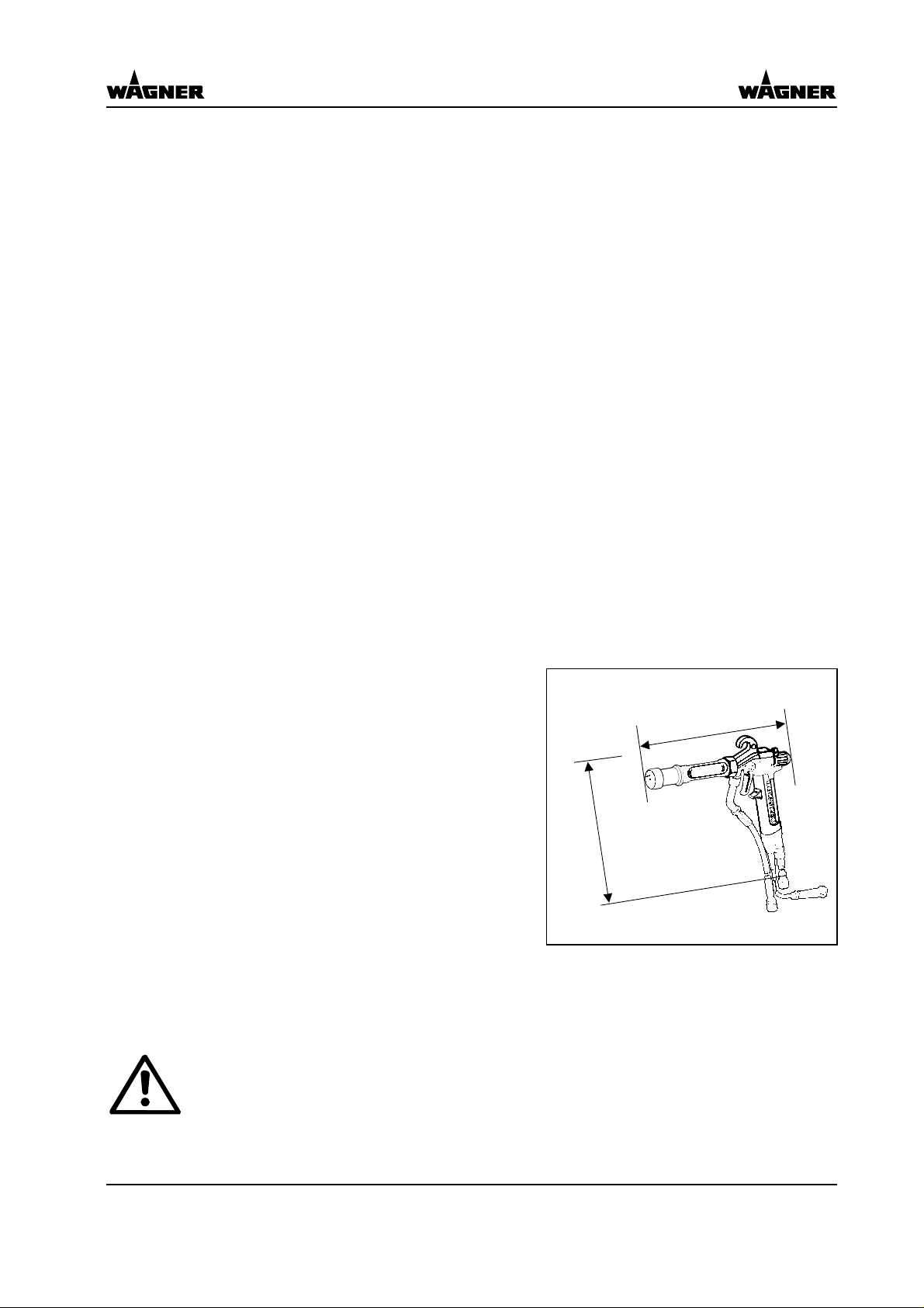
2.3.1 Functions of the gun
300
255
Attention
The electrostatic spray gun GM 2000 EAC EN can only be used with the control units
VM 200 EN, VM2000 EN or EPP 200 EN.
continued....
2.1
Page 12

GM 2000 EAC - EN
● The trigger can be used to
activate, one after the other, the
various functions of the spray
gun.
An increase in the tension
needed to pull the trigger back
will be felt at the position where
the material valve opens.
● In order to overcome Faraday
cages in corners, the high voltage can be switched off by flipping the HV switch (F) down.
● The supply of atomizing and flat
jet air is adjusted by means of
the star handles (D)
Legend
A Tip
B Tip nut
C Spray gun body
D Air control knob
E Locking nut for trigger
F HV flip switch (integrated into
trigger)
G Handle with integrated high vol-
tage generator
H Air connection
I Cable connection
K Paint connection
L Trigger
M Paint filter
A
AirCoat - air open
AirCoat - air open and
electrostatics activated
AirCoat - air open, electrostatics
activated and material valve open
B
C
LM
K
D
E
F
G
H
I
2.2
Page 13

GM 2000 EAC - EN
2.3.2 AirCoat round jet process
In the AirCoat process, high pressure of 30 to 150 bar is used to atomize the material.
The AirCoat air at 0 to 2.5 bar produces a soft jet, which largely eliminates the problem
of overlapping boundaries. The spray jet can be adjusted by turning the nozzle nut.
The multi-channel swirl nozzle produces fine paint particles, while at the same time
reducing their forwards speed and swirling them to produce a rotating motion. The
result is a soft, extremely well atomized spraying cloud.
Advantages of AirCoat
Nozzle nut
● High painting capacity
● Low fogging tendency
● Good finish
● High- viscosity paints can easily
be applied
2.3.3 AirCoat flat jet process
In the AirCoat process, high pressure of 30 to 150 bar is used to atomize the material.
The AirCoat air at 0 to 2.5 bar produces a soft jet, which largely eliminates the problem
of overlapping boundaries.
Advantages of AirCoat
● High painting capacity
● Low fogging tendency
● Good finish
● High- viscosity paints can easily
be applied
AirCoat air
Material
AirCoat air
Multi-channel swirl nozzle
AirCoat air
Material
AirCoat air
2.3
Page 14

2.3.4 Electrostatic effect
The spray gun produces an electrostatic field by means of the high voltage electrode.
As a result, the particles of paint, which have been atomized by the spray gun, are
carried to the earthed object by kinetic and electrostatic energy where they adhere,
finely distributed, to the object being sprayed.
GM 2000 EAC - EN
Charged particles
Advantages of
electrostatics:
● Very efficient spraying
● Little overspray
● Coating of entire cir-
cumferences due to an
electrostatic field
● Less working time
Grounded object
2.4 What kind of spraying material can be applied?
● Paints containing solvents of the explosion class II A.
● Enamels, primers, textured paints etc., which have a specific resistance of > 50 kΩ
(according to the Wagner or Ransburg scale).
● The effectiveness of the spraying action is always dependant on the composition
of the paint being used, e.g. pigments, resins and solvents.
Electrode
Note
With highly conductive materials, or those with a very high electrical resistance, the
electrostatic effect does not work so efficiently.
In the case of application problems contact the Wagner branch and the paint producer.
2.4
Page 15

GM 2000 EAC - EN
3. PREPARATION BEFORE STARTING WORK
Caution
The operating instructions and the safety regulations for the additional system
components used must be read before starting-up .
This spray gun must be used a part of an AirCoat-Electrostatic spraying system.
The control units VM 200 EN, VM 2000 EN or EPP 200 EN and other various
components are also needed (see Wagner-accesories).
The spray gun and paint supply system must be flushed out with a suitable cleaning
solvent before being used.
3.1 Preparation of paint
The viscosity of the paints is of great importance. The best results are obtained with
paints between 18 and 30 DIN sec. (measured in immersion flow cup DIN 4 mm). In
most cases, the application of paints of up to 50-60 DIN sec. for thick layers does not
cause problems.
3.2 Earthing
Perfect earthing is a prerequisite for optimum coating efficiency and safety.
The imperfect earthing of a workpiece will result in:
● Sparks between the object being sprayed and the suspension hook.
● Insufficient electrostatic effect (no wrap-around)
● Uneven coating thickness
● Back spraying to spray gun and sprayer
The prerequisites for perfect earthing and coating are:
● Clean workpiece suspension.
● Earthing of spraying cabin, conveyor system and suspension with 10mm
cable to system earth, earthing strip or ring.
● Earthing of all conductive parts within the working area.
● The earthing resistance of the workpiece may not exceed 1 M
conveyor
Control unit
Object to be
sprayed
Pump
R max < 1 M
Ω.
2
copper
Paint container
Floor, conductive
3.1
Spraying stand
Page 16

Empty page
GM 2000 EAC - EN
3.2
Page 17

GM 2000 EAC - EN
4. STARTING WORK, AND HANDLING
Caution
See SAFETY REGULATIONS in chapter 1.
4.1 Preparation
● Locking of spray gun! Turn locking nut clockwise until stop (viewed from back of
gun)
● Check that spraying pressures are suitable.
● Check that all connections are tight and do not leak.
4.2 General rules for handling the spray gun
The following rules must be observed before any work is carried out on the
equipment or during breaks in work:
● Switch off control unit.
● Relieve spray gun and system pressure.
● Lock the spray gun with the locking nut.
4.3 Start-up for AirCoat spraying
1. Connect earth cable to the earth terminal of the control unit. Fix the other end using
the clamp to the nearest earthed piece of the equipment (cabin, transport device,
or similar). Make sure that all other conductive parts within the work area are
earthed.
2. Connect material hose to spray gun and to pump.
3. Connect air hose to spray gun and to oil-free, dry air supply with regulator.
4. Connect cable to control unit VM 200 EN or EPP 200 EN.
5. Set material pressure (approx. 80 bar) at material pump and switch on control unit.
6. Spray (actuate trigger).
7. Adjust spraying pressure at the paint pump regulator, according to jet and object.
8. Now open AirCoat air (approx. 1 to 2.5 bar) and adjust for the optimum atomization.
Adjusting round jet fan:
9. By turning the tip nut , the atomizing air jet can additionally be adjusted.
By exchanging tips, various paint outputs can be achieved.
Note
Do not close the gap for atomizing air between tip nut and body.
for flat jet process :
9. To change the jet width; fit another AirCoat flat jet nozzle, with the required fan angle.
By exchanging tips, various paint outputs can be achieved.
4.1
Page 18

GM 2000 EAC - EN
4.4 Cleaning of clogged round jet tips
1. By means of tip spanner (A),
loosen tip insert (B) by a half turn.
2. Remove tip spanner and briefly pull
trigger. Caution, never spray into
an enclosed vessel.
3. After cleaning the tip retighten.
A
4.5 Exchange of Aircoat round jet tip insert (EAC round)
B
1. Remove tip insert (B) with tip spanner (A).
2. Fit desired tip insert (acc. to table
7.1) with tip spanner.
A
B
4.6 Changing from AirCoat round jet to AirCoat flat jet.
1. Replace paint with cleaning solvent, actuate trigger, and thoroughly rinse paint channel.
2. Relieve spray gun and system
pressure.
3. Lock spray gun. Turn locking screw
clockwise until stop. (Look in spraying direction)
4. Unscrew tip nut (C).
5. Remove tip body (D) by means of
pin wrench.
6. Fit tip insert (F) on paint channel
(G).
7. Fit air cap (H) onto fan nozzle (F);
make sure that the pins in the air
cap fit into the grooves in the flat
nozzle.
8. Fit cap ring (I) with air cap (H) onto
spray gun body (E).
9. Adjust desired jet level by means of
air cap horns (X) and tighten cap
ring (I) by hand.
Universal spanner
C
I
D
H
X
F G
E
E
4.2
Page 19

GM 2000 EAC - EN
4.7 Replacing AirCoat flat jet tips
1. Switch off control unit.
2. Relieve spray gun and system
pressure!
3. Lock spray gun. Turn locking screw
clockwise until stop. (look in spraying direction)
4. Unsrew cap ring (I) and remove air
cap (H).
5. Remove AirCoat tip insert (F) and
brush cleaning solvent until all traces of paint are dissolved.
Handle the hard metal tip insert (C) with care. Do not clean it with sharp metal objects.
6. Assembly: Fit tip insert (F) on paint channel (G).
7. Fit air cap (H) onto fan nozzle (F); make sure that the pins in the air cap fit into the
grooves in the tip.
8. Fit cap ring (I) with air cap (H) onto spray gun body (E).
9. Adjust desired jet level by means of air cap horns (X) and tighten cap ring (I) by
hand.
I
H
X
F G
E
4.8 Cleaning of AirCoat flat jet tips
For disassembly and assembly see of AirCoat nozzles chapter 4.7.
The AirCoat nozzle (F) can be placed into a cleaning solvent which has been
recommended by the paint manufacturer. Do not treat the hard metal on the AirCoat
nozzle using sharp edged objects.
4.9 Clogging of AirCoat flat jet tips
For blockages in the AirCoat flat jet tip the accessory - tip cleaning device - is available
with the partnumber 0139 014.
This tip cleaning device can be used together with the GM 2000 EAC to flush out
blocked AirCoat flat jet tips in the opposite direction to the usual spray direction.
4.3
Page 20

Empty page
GM 2000 EAC - EN
4.4
Page 21

GM 2000 EAC - EN
5. MAINTENANCE
Caution
See SAFETY REGULATIONS in chapter 1.
Attention
The spray gun and the system must be cleaned every day. Use only the cleaning solvent recommended by the material manufacture.
Never immerse the spray gun into the solvent.
The following points must be observed before every maintenance works:
● Switch off control unit.
● Relieve spray gun and system pressure.
● Secure the spray gun.
5.1 Decommissioning and cleaning
1. Switch off control unit.
2. Relieve system pressure and cut off the air supply to the spray gun.
3. Replace material by cleansing agent.
if the round jet nozzle is fitted
4. By means of tip spanner (A), loosen tip insert (B) by a half turn.
5. Remove tip spanner and briefly actuate trigger. Caution, never spray into an enclosed vessel.
6. Relieve spray gun and system pressure !
7. Tighten tip insert.
8. Clean the body of the gun with solvent which has been recommended by the paint
manufacturer and dry with a cloth or blow gun.
if the flat jet nozzle is fitted
5. Remove and clean the AirCoat tip. (see chapter 4.5)
6. Actuate trigger and thoroughly rinse paint channel.
Never spray into an enclosed vessel.
7. Relieve spray gun and system pressure!
8. Clean the body of the gun with solvent which has been recommended by the paint
manufacturer and dry with a cloth or blow gun.
Note
Keep the gun pointing downwards or horizontally, cleaning agent must not get into the air ducts.
The gun attachment (X) may only be changed
by the WAGNER Service Station.
5.1
X
Page 22

GM 2000 EAC - EN
5.2 Dissassembly of AirCoat nozzle body (round jet)
1. Unscrew tip nut.
2. Remove nozzle body (3) with
spanner (B)
3. Unscrew tip insert (1) with tip
spanner (A)
4. Push threaded nozzle fitting (2)
backwards out of the nozzle
body (3).
5. Handle the round-jet tip insert (1)
and threaded fitting (2) with care,
do not clean with sharp metal
objects. Use nozzle cleaning
brush
(parts no. 9997 001).
Replace any worn-out parts.
Assemble in reverse order.
1
B
A
2
3
Note (round jet EAC)
Care must be taken when assembling that the tip nut is not tight to the nozzle body (3).
There must be room for the AirCoat air between nut and nozzle body.
5.3 Exchange or cleaning of filters
1. Place spanner, size 11, on surfa-
ce (2) of material connection (3)
and counterhold.
2. Turn union nut (1) to the right
(clockwise) with open-end
wrench, size 17, and unscrew
material connection.
3. Do not unscrew counter nut (A),
as the connection will leak.
4. Remove filter screw (5) and
withdraw cylindrical filter (4).
5. Clean filter (4) with solvent, or
exchange it.
A
2
4
5
3
1
Assemble in reverse order.
3
5.2
Page 23

GM 2000 EAC - EN
5.4 Adjustment of the valve rod seal
In case paint leaks at the valve rod
near the trigger:
1. Pull trigger and throughly
clean paint channel with solvent.
2. Tighten the sealing screw (A) ca-
refully with universal spanner
3. If leaking continues, see chapter
5.5.
5.5 Exchange of complete valve rod, or of valve rod seals
1. Pull trigger (Y) and unscrew
locking nut (X); remove compression spring.
2. Remove flat-head screw (Z) and
take off trigger (Y).
3. Unscrew sealing screw (4/B)
from sealing sleeve (5).
4. Carefully remove complete valve
rod at surface (F) and replace.
To replace seals:
5. Hold with universal spanner at
surface (E) and unscrew valve
sealing element (1/A) using universal pliers.
Z
Y
A
X
1
Loctite 243
3
2
4
5 6
A B C
7
8
Loctite 243
9
E
D
F
6. Remove compression ring (2) and packing (3).
7. Hold with spanner at surface (D) and unscrew at surface (C), removing push-rod
cap (7).
8. Exchange compression ring (with O-ring) (2), front seal (3), rear seal (4), push-rod
seal (8) and replace air valve seal (9) of the air valve.
9. Reassemble in reverse order and secure thread with Loctite 243.
10. Place locking nut (X) with compression spring in position. Actuate trigger (Y) and
tighten the locking nut (X) until a noticeable resistance is felt.
5.3
Page 24

GM 2000 EAC - EN
5.6 Exchange of paint channel
● if the round jet nozzle is fitted
1. Unscrew tip nut (1).
2. Unscrew tip body (2) with universal spanner.
3. Unscrew seal screw (3) with paint channel assembly tool.
4. Remove paint channel.
Assemble in reverse order, use screw (3) again.
● if the flat jet nozzle is fitted
1. Unscrew cap ring (5).
2. Remove air cap (6) and AirCoat tip (7).
3. Unscrew seal screw (3) with paint channel assembly tool.
4. Remove paint channel.
Re-Assemble in reverse order, use screw (3) again.
Note
Insert the paint channel as shown below (note position of the shoulder for the seal
screw)
2
1
Universal spanner
Round jet
4
3
Paint channel assembly tool
5
5.4
Flat jet
6
7
Page 25

GM 2000 EAC - EN
6. TROUBLE SHOOTING AND SOLUTIONS
Problem
Insufficient material
output
Poor spray pattern
Cause
• Tip too small
• Material pressure too low
• Gun filter or high-pressure
filter in pump blocked
• AirCoat tip (round) clogged
• Wrongly adjusted atomizing
air
• Tip too large
• Material pressure too low
• Material viscosity too high
Solution
• Select larger tip (see chapter
7.1 and 7.2)
• Increase material pressure
• Clean or exchange filter
• Clean tip (see chapter 4.4,
4.8 and 4.9)
• Readjust the atomizing air
• Select smaller tip (see chapter 7.1 and 7.2)
• Increase material pressure
• Thin material acc. to manufacturer's instruction.
Leaking air valve
Poor wrap round or
electrostatic effect
Back spraying
No electrostatic effect
(no wrap around)
• Damaged seals on the valve
rod
• Poor earth
• Paint conductivity too high /
resistance paint too high
• Spraying pressure too high
• No earth
• Distance between spray gun
and workpiece too large.
• High voltage switched off ?
• High voltage failure
• Exchange seals (see chapter
5.4 and 5.5)
• Check earth of object
• Check resistance of paint
(see chapter 2.4)
• Adjust spraying pressure
• Check earth. (see chapter
3.2)
• Reduce distance between
spray gun and workpiece.
• Switch on high voltage.
• Repair failure acc. to operating instructions of control
unit.
6.1
Page 26

Empty page
GM 2000 EAC - EN
6.2
Page 27

7. ACCESSORIES
7.1 Round jet tip inserts
The round jet tips are especially suited to spray pipes, profiles and
complex workpieces.
Part-No. Marking Volume flow Jet width Recommended filter
0132 720 R 11 0.160 appr. 250 mm
0132 721 R 12 0.220 appr. 250 mm
0132 722 R 13 0.270 appr. 250 mm 180 mesh
0132 723 R 14 0.340 appr. 250 mm
0132 724 ✕ R 15 0.380 appr. 250 mm
0132 725 R 16 0.430 appr. 250 mm
0132 726 R 17 0.480 appr. 250 mm 100 mesh
0132 727 R 18 0.530 appr. 250 mm
0132 728 R 19 0.590 appr. 250 mm
0132 729 R 20 0.650 appr. 250 mm
0132 730 R 21 0.710 appr. 250 mm 50 mesh
0132 731 R 22 0.770 appr. 250 mm
GM 2000 EAC - EN
1) 2)
✕ Standard tip
1) Volume flow in l/min water at 100 bar
2) Jet width in mm at a distance of 30 cm from the object and at a pressure of
100 bar
7.1
Page 28

7.2 AirCoat flat tips
AirCoat flat jet tips are used for fast, economic application of material to
flat workpieces.
Part Marking size Spraying Volume Jet Recommended
number mm / inch angle flow 1) width 2) filter
0128 564 07.40 0.18-0.007 40 0.19 160
0128 550 09.10 0.23-0.009 10 0.26 90
0128 216 09.20 0.23-0.009 20 0.26 120
0128 567 09.40 0.23-0.009 40 0.26 170
0128 211 09.50 0.23-0.009 50 0.26 200 180 mesh
0128 551 09.60 0.23-0.009 60 0.26 220
0128 552 11.10 0.28-0.011 10 0.38 100
0128 217 11.20 0.28-0.011 20 0.38 125
0128 568 11.40 0.28-0.011 40 0.38 190
0128 201 11.50 0.28-0.011 50 0.38 210
0128 573 11.60 0.28-0.011 60 0.38 235
0128 553 11.80 0.28-0.011 80 0.38 290
0128 554 13.10 0.33-0.013 10 0.57 100
0128 218 13.20 0.33-0.013 20 0.57 120
0128 569 13.40 0.33-0.013 40 0.57 200
0128 212 13.50 0.33-0.013 50 0.57 220
0128 574 13.60 0.33-0.013 60 0.57 250
0128 555 13.80 0.33-0.013 80 0.57 310 100 mesh
0128 556 15.10 0.38-0.015 10 0.72 115
0128 219 15.20 0.38-0.015 20 0.72 145
0128 570 15.40 0.38-0.015 40 0.72 210
0128 213 15.50 0.38-0.015 50 0.72 250
0128 575 15.60 0.38-0.015 60 0.72 270
0128 557 15.80 0.38-0.015 80 0.72 330
0128 220 18.20 0.46-0.018 20 1.14 140
0128 571 18.40 0.46-0.018 40 1.14 250
0128 215 18.50 0.46-0.018 50 1.14 270
0128 558 18.80 0.46-0.018 80 1.14 380
0128 565 21.20 0.53-0.021 20 1.56 190
0128 572 21.40 0.53-0.021 40 1.56 270 50 mesh
0128 559 21.50 0.53-0.021 50 1.56 290
0128 560 21.80 0.53-0.021 80 1.56 430
0128 561 26.50 0.66-0.026 50 2.32 300
0128 562 31.50 0.79-0.031 50 3.50 300
0128 563 36.50 0.91-0.036 50 4.56 300
GM 2000 EAC - EN
1) Volume flow in l/min water at 100 bar
2) Jet width in mm at a distance of 30 cm from the object and at a pressure of 100
bar, synthetic resin paint, 20 DIN seconds
7.2
Page 29

7.3 Filter (standard)
GM 2000 EAC - EN
Description Mesh
Cylindrical filter 180 0179 931 0179 932 0179 933 R 11 - R 15 .007" - .011"
Cylindrical filter 100 0179 934 0179 935 0179 936 R 16 - R 19 .012" - .015"
Cylindrical filter 50 0179 937 0179 938 0179 939 R 20 - R 22 .018" - .036"
Part No.
for 6 pcs.
Part No.
for 12 pcs.
7.4 Long filter housing and and filters
Part No. Description
0179 160 Filter housing cpl.
Description Mesh
Gun filter, red 180 0034 383 0097 022 R 11 - R 15 .007" - .011"
Gun filter, yellow 100 0043 235 0097 023 R 16 - R 19 .012" - .015"
Gun filter, white 50 0034 377 0097 024 R 20 - R 22 .018" - .036"
Part No.
for 1 pc.
Part No.
for 24 pcs.
Part No.
for 10 pcs.
For use with nozzle sizes
round flat
For use with nozzle sizes
round flat
7.5 Hoses and fittings
Part No. Description
0229 200 Air and HP hose DN4 - ND 270 - M16 x 1.5 - length 7.5 m
0128 510 Air hose cpl. length 8.1 m
9984 481 HP- Hose DN 4 - ND 270 - M16 x 1.5 - length 7.5 m
9982 016 Prtective hose cover (lengths order in m )
0179 228 Extension cable EN, length 7.5 m
0123 446 Double nipple M16x1.5 (for paint hoses)
9994 627 Double nipple R1/4 " (for air hoses)
7.6 Special tools
Part No. Description
0179 926 Paint channel tool
0128 901 Tip spanner
0179 901 Universal spanner
0179 799 Service Instruction GM 2000 EA EN + EAC EN
7.3
Page 30

Empty page
GM 2000 EAC - EN
7.4
Page 31

GM 2000 EAC - EN
8. SPARE PARTS CATALOGUE
8.1 How to order spare parts?
Always supply the following information to ensure delivery of the right spare part:
Part No., description and quantity.
The quantity need not be the same as the number given in the "Quantity" column. This
number merely indicates the how many of the respective parts are used in each subassembly.
The following information is also required to ensure smooth processing of your order:
Address for the invoice
Address for delivery
Name of the person to be contacted in the event of any queries
Type of delivery required
8.2 Special marks in spare parts lists
Note to column "K" in the following spare parts list:
❋ = Wearing part
● = Not a part of the standard equipment. Available, however, as additional extra
8.1
Page 32

8.3 Spare parts list
Item Part No. K Quantity Description
2 0179 354 1 Positioning bush
3 9900 962 1 Countersunk screw M3x12
4 0179 564 1 Data plate GM 2000 EAC R EN
4 0179 569 1 Data plate GM 2000 EAC F EN
5 9900 810 2 Flat head screw
6 9971 003 ❋ 1 O-ring green 6x1
7 0179 416 1 Air control knob
8 0179 396 ❋ 1 Trigger pin
9 0179 254 1 Valve stem assy.
10 0179 236 1 Valve ball
11 9971 182 ❋ 1 O-ring 4x1
12 0179 343 1 Thrust collar
13 0179 341 ❋ 1 Needle packing
14 0179 342 ❋ 1 Sealing screw
15 0179 340 1 Tappet cap
16 0179 395 ❋ 1 Seal
17 0179 339 1 Tappet seal
18 0179 338 ❋ 1 Air valve seal
19 0179 337 1 Valve tappet
20 0179 335 1 Valve stem
21 0179 394 1 Spring guide - valve stem
22 9994 247 1 Compression spring
23 0179 253 1 Adjuster for valve rod
24 9994 248 1 Compression spring
25 0179 488 1 Spring seat EAC/AC
26 0179 356 1 Tension nut
27 9994 627 1 Double nipple R1/4"
28 0128 510 ● 1 Air hose
30 0179 248 ● 1 Hose cover
31 9900 808 ❋ 1 Pan-head screw M3x8
32 0179 219 ❋ 1 Trigger
33 9995 611 ❋ 1 Cylinder filter 180 M
34 0179 383 1 Filter screw
35 0179 241 1 Paint connector
36 9984 481 ● 1 HP-hose DN4 - ND270 - M16x1.5 - 7.5 m
37 0179 643 1 Flat jet kit, 2000 EAC
38 0179 465 1 Cap ring 2000 EAC
39 0179 644 1 Air cap, 2000 EAC
40 0128 ... ● 1 AirCoat - flat tip (see chapter 7.2)
41 0179 485 1 Paint channel
42 0179 486 1 Seal screw
43 0179 452 1 Tip nut 2000 EAC
44 0132 724 ❋ 1 Round jet tip R15 (see chapter 7.1)
45 0132 351 1 R-Tip holder
46 0132 516 ❋ 1 Distributor
47 0179 642 1 Nozzle body 2000 EACR
48 0179 641 1 Nozzle set 2000 EACR
49 9994 269 1 Contact spring
50 0179 521 ● 1 Long filter housing
51 0043 590 ● 1 Compression spring
52 0128 389 ● 1 Seal
53 0128 347 ● 1 Hose connector M16x1.5
54 0179 160 ● 1 Long filter housing assembly
55 .... ... ● 1 Gun filter (see chapter 7.4.)
0179 926 ● 1 Paint channel assembly tool
0179 946 1 Set of seals EA/EAC/AC
GM 2000 EAC - EN
8.2
Page 33

GM 2000 EAC - EN
48
49
41
40
39
50
55
53
52
51
54
37
8.3
42
38
Page 34

Empty page
GM 2000 EAC - EN
8.4
Page 35

Page 36

England / United Kingdom
WAGNER Spraytech (UK) Lt. Telephone ++44 / (0)1295/ 265 353
Haslemere Way Telefax ++44 / (0)1295/ 269 861
Tramway Industrial Estate
GB- Banbury OXON OX16 8TY E-Mail: enquiry@wagnerspraytech.co.uk
Deutschland / Germany
J. WAGNER GmbH Telephone ++49/ (0)7544 / 5050
Otto-Lilienthal-Str. 18 Telefax ++49/ (0)7544 / 505200
Postfach 1120
D- 88677 Markdorf E-Mail: support@wagner-group.com
Schweiz / Switzerland
WAGNER International AG Telephone ++41/ (0)71 / 757 2211
Industriestrasse 22 Telefax ++41/ (0)71 / 757 2222
Postfach 109
CH- 9450 Altstätten E-Mail: rep-ch@wagner-group.ch
www.wagner-group.com
 Loading...