


Translation of the original
Operating manual
GM 5000EAC
Electrostatic AirCoat Spray gun
for manual operation with flat or round jet nozzles
Edition 03/2012
 II 2 G EEx 0.24 mJ
0102
B_03154
c |
us |
(in submission) |

GM 5000EAC.
EDITION 03/2012 |
PART NUMBER DOC 2319150 |
OPERATING MANUAL
Contents
1 |
ABOUT THESE INSTRUCTIONS |
6 |
1.1 |
Languages |
6 |
1.2 |
Warnings, notes and symbols in these instructions |
6 |
2 |
GENERAL SAFETY INSTRUCTIONS |
7 |
2.1 |
Safety instructions for the operator |
7 |
2.1.1 |
Electrical equipment |
7 |
2.1.2 |
Personnel qualifications |
7 |
2.1.3 |
A safe work environment |
7 |
2.2 |
Safety instructions for staff |
7 |
2.2.1 |
Safe handling of WAGNER spray units |
8 |
2.2.2 |
Earth the unit |
8 |
2.2.3 |
Material hoses |
8 |
2.2.4 |
Cleaning |
9 |
2.2.5 |
Handling hazardous liquids, varnishes and paints |
9 |
2.2.6 |
Touching hot surfaces |
10 |
2.3 |
Correct use |
10 |
2.4 |
Safety-relevant information about discharges |
11 |
2.5 |
Use in an explosion hazard area |
11 |
2.5.1 |
Correct use |
11 |
2.5.2 |
Explosion protection identification CE |
11 |
2.5.2.1 |
Identification„X“ |
11 |
2.5.3 |
Explosion protection identification FM |
12 |
2.6 |
German regulations and guidelines |
12 |
3 |
GUARANTEE AND CONFORMITY DECLARATIONS |
13 |
3.1 |
Important notes on product liability |
13 |
3.2 |
Guarantee claim |
13 |
3.3 |
CE-Conformity |
14 |
4 |
DESCRIPTION |
15 |
4.1 |
Fields of application, using in accordance with the instructions |
15 |
4.1.1 |
Processable materials |
15 |
4.2 |
Scope of delivery |
16 |
4.3 |
Technical data |
17 |
4.4 |
Functional description |
18 |
4.4.1 |
Design of spray gun (standard variant) |
18 |
4.4.2 |
Functions of the spray gun |
19 |
4.5 |
Spraying process |
20 |
4.5.1 |
AirCoat round jet spray process |
20 |
4.5.2. |
AirCoat atomizing flat jet spray process |
20 |
4.5.3 |
Electrical resistance |
21 |
5 |
START-UP AND OPERATION |
22 |
5.1 |
Installation and connection |
22 |
5.1.1 |
Typical electrostatic spraying system |
22 |
5.1.2 |
Ventilation of the spray booth |
23 |
5.1.3 |
Air supplies |
23 |
5.1.4 |
Paint supplies |
24 |
5.1.5 |
Earthing |
25 |
3

GM 5000EAC.
EDITION 03/2012 |
PART NUMBER DOC 2319150 |
OPERATING MANUAL
Contents
5.2 |
Preparation of paints |
27 |
5.2.1 |
Viscosity conversion table |
27 |
5.3 |
Start-up |
28 |
5.3.1 |
General rules for making adjustments to the spray gun |
28 |
5.3.2 |
Preparation for starting up |
28 |
5.4 |
Working |
30 |
5.4.1 |
Filling with working material |
30 |
5.4.2 |
Start-up for spraying AirCoat |
31 |
5.4.3 |
Cleaning of clogged round jet nozzles |
32 |
5.4.4 |
Exchange of round jet nozzle insert |
32 |
5.4.5 |
Changing from AirCoat round jet to AirCoat flat jet |
33 |
5.4.6 |
Replacing AirCoat flat jet nozzles |
34 |
5.4.7 |
Cleaning of the nozzles |
34 |
5.4.8 |
Eliminate nozzle clogging |
34 |
6 |
MAINTENANCE |
36 |
6.1 |
Periodically checks |
36 |
6.2 |
Cleaning and decommissioning |
36 |
6.3 |
Dismantling of the spray gun |
38 |
6.4 |
Cleaning the parts after disassembly |
41 |
6.5 |
Assembling the spray gun |
42 |
6.6 |
Function test after assembly of the gun |
46 |
6.6.1 |
Checking the high-voltage |
46 |
6.6.2 |
Air tests |
47 |
6.6.3 |
Material pressure test |
47 |
6.6.4 |
Check spray pattern |
48 |
7 |
TROUBLE SHOOTING AND SOLUTION |
49 |
8 |
PRODUCT DISPOSAL |
50 |
9 |
ACCESSORIES |
51 |
9.1 |
ACR 5000 round jet nozzle cap |
51 |
9.1.1 |
AirCoat round jet nozzle inserts |
51 |
9.2 |
ACF 5000 air caps (flat jet) |
51 |
9.2.2 |
ACF 5000 AirCoat flat jet nozzles |
52 |
9.3 |
Filters |
54 |
9.4 |
Reduction fittings for high-pressure hoses |
54 |
9.5 |
Hoses and electrical cables |
55 |
9.5.1 |
Standard hose sets and components |
55 |
9.5.2 |
Hose sets for low impedance materials |
56 |
9.5.3 |
Gun cable and gun cable extensions |
57 |
9.6 |
Miscellaneous |
57 |
4

GM 5000EAC.
EDITION 03/2012 |
PART NUMBER DOC 2319150 |
OPERATING MANUAL
Contents
10 |
SPARE PARTS |
59 |
10.1 |
How to order spare parts? |
59 |
10.2 |
GM 5000EAC spare parts list |
60 |
10.2.1 |
GM 5000EAC spare parts listEnd piece |
62 |
10.2.2 |
GM 5000EAC spare parts list - Handle |
64 |
10.3 |
Accessories spare parts lists |
66 |
10.3.1 |
Flat jet nozzles spare parts list |
66 |
10.3.2 |
ACR 5000 round jet nozzle cap spare parts list |
67 |
5
GM 5000EAC.
EDITION 03/2012 |
PART NUMBER DOC 2319150 |
OPERATING MANUAL
1 ABOUT THESE INSTRUCTIONS
4HISIOPERATING MANUALMCONTAINSAINFORMATION ABOUT THE OPERATION REPAIRPANDIMAINTENANCE OF THE UNIT
!LWAYS FOLLOWWTHESEHINSTRUCTIONSOWHEN OPERATING THE UNIT
4HISIEQUIPMENTUCANPBE DANGEROUS IFNIT ISENOTDOPERATED INOACCORDANCE WITH THIS MANUAL %LECTROSTATICTSPRAYYGUNS MAYYBE OPERATED ONLYOBYYTRAINEDNPERSONNEL
#OMPLIANCEIWITH THESEEINSTRUCTIONSOCONSTITUTES AN INTEGRAL COMPONENTEOF THEHGUARANTEE AGREEMENT
1.1 LANGUAGES |
|
|
|
4HISIOPERATINGEMANUAL ISNAVAILABLEAIN THE FOLLOWING LANGUAGES |
|
||
,ANGUAGE |
0ARTT.O |
,ANGUAGE |
0ARTT.O |
'ERMAN |
2310481 |
%NGLISH |
2319150 |
&RENCH |
2320152 |
$UTCH |
- |
)TALIAN |
2320153 |
3PANISH |
2320154 |
1.2 WARNINGS, NOTES AND SYMBOLS IN THESE INSTRUCTIONS
Warning instructions in this manual point out particular dangers to users and equipment and state measures for avoiding the hazard.
These warning instructions fall into the following categories:
Danger - imminent danger. Non-observance will result in death, serious injury and serious material damage.
 DANGER
This line warns of the hazard!
Possible consequences of failing to observe the warning instructions. The signal word points out the hazard level.
SIHI_0100_GB The measures for preventing the hazard and its consequences.
Warning - possible danger. Non-observance can result in death, serious injury and serious material damage.
 WARNING
This line warns of the hazard!
Possible consequences of failing to observe the warning instructions. The signal word points out the hazard level.
The measures for preventing the hazard and its consequences.
SIHI_0103_GB
Caution - a possibly hazardous situation. Non-observance can result in minor injury.
Caution - a possibly hazardous situation. Non-observance can cause material damage.
|
CAUTION |
|
|
|
This line warns of the hazard! |
|
Possible consequences of failing to observe the warning instructions. |
|
The signal word points out the hazard level. |
SIHI_0101_GB |
The measures for preventing the hazard and its consequences. |
|
|
|
|
SIHI_0102_GB |
CAUTION |
This line warns of the hazard!
Possible consequences of failing to observe the warning instructions. The signal word points out the hazard level.
The measures for preventing the hazard and its consequences.
Note - provide information on particular characteristics and how to proceed.
6
GM 5000EAC.
EDITION 03/2012 |
PART NUMBER DOC 2319150 |
OPERATING MANUAL
2 GENERAL SAFETY INSTRUCTIONS
2.1 SAFETY INSTRUCTIONS FOR THE OPERATOR
Keep these operating instructions to hand near the unit at all times.
Always follow local regulations concerning occupational safety and accident prevention.
2.1.1 ELECTRICAL EQUIPMENT
Electrical plant and unit
To be provided in accordance with the local safety requirements with regard to the operating mode and ambient influences.
May only be maintained by skilled electricians or under their supervision.
Must be operated in accordance with the safety regulations and electrotechnical regulations.
Must be repaired immediately in the event of problems.
Must be put out of operation if they pose a hazard.
Must be de-energized before work is commenced on active parts. Inform staff about planned work, observe electrical safety regulations.
2.1.2 PERSONNEL QUALIFICATIONS
%NSURE THATETHETUNIT IS OPERATED AND REPAIREDIONLY BYYTRAINEDAPERSONS
2.1.3 A SAFE WORK ENVIRONMENT
Make sure that the floor in the area where you are working is anti-static in accordance with EN 61340-4-1 (the resistance value may not exceed 100 MOhm).
Ensure that all persons within the working area wear antistatic shoes. Footwear must comply with EN 20344.The measured insulation resistance may not exceed 100 MOhm. Ensure that during spraying, persons wear anti-static gloves so that they are earthed via the handle of the spray gun.
If protective clothing is worn, including gloves, it has to comply with EN 1149-5. The measured insulation resistance may not exceed 100 MOhm.
Paint mist extraction systems must be fitted on site according to the local regulations. Ensure that the following components of a safe working environment are available:
–Material/air hoses adapted to the working pressure.
–Personal safety equipment (breathing and skin protection).
Ensure that there are no ignition sources such as naked flame, glowing wires or hot surfaces in the vicinity. Do not smoke.
2.2 SAFETY INSTRUCTIONS FOR STAFF
Always follow the information in these instructions, particularly the general safety instructions and the warning instructions.
Always follow local regulations concerning occupational safety and accident prevention.
7

GM 5000EAC.
EDITION 03/2012 |
PART NUMBER DOC 2319150 |
OPERATING MANUAL |
|
2.2.1 SAFE HANDLING OF WAGNER SPRAY UNITS
The spray jet is under pressure and can cause dangerous injuries. Avoid injection of paint or cleaning agents:
Never point the spray gun at people.Never reach into the spray jet.
Before all work on the unit, in the event of work interruptions and functional faults:
– Switch off the energy/compressed air supply.
– Secure the spray gun against actuation.
– Relieve the pressure from the spray gun and unit.
–By functional faults: Identify and correct the problem, proceed as described in chapter „Trouble shooting“.
In the event of skin injuries caused by paint or cleaning agents:
Note down the paint or cleaning agent that you have been using.
Consult a doctor immediately.
Avoid danger of injury through recoil forces:
Ensure that you have a firm footing when operating the spray gun.
Only hold the spray gun briefly in any one position.
2.2.2 EARTH THE UNIT
Depending on the high-voltage of the spray electrode and the flow rate at spray pressures can produce an electrostatic charge in the equipment. These can cause sparks and flames upon discharge.
Ensure that the unit is always earthed.
Earth the work pieces to be coated.
Ensure that all persons inside the working area are earthed, e.g. that they are wearing derivable shoes.
When spraying, wear derivable gloves to earth yourself via the spray gun handle.
2.2.3 MATERIAL HOSES
Ensure that the hose material is chemically resistant to the sprayed materials.
Ensure that the material hose is suitable for the pressure generated in the unit.
Ensure that the following information is visible on the high pressure hose:
–Manufacturer
–Permissible operating overpressure
–Date of manufacture.
The electrical resistance of the complete high pressure hose must be less than 1 MOhm.
8

GM 5000EAC.
EDITION 03/2012 |
PART NUMBER DOC 2319150 |
OPERATING MANUAL |
|
2.2.4 CLEANING
De-energize the unit electrically.
Disconnect the pneumatic supply line.
Relieve the pressure from the unit.
Ensure that the flash point of the cleaning agent is at least 15K above the ambient temperature. Otherwise, the cleaning works shall be carried out at forced ventilated cleaning place.
To clean, use only solvent-soaked cloths and brushes. The cleaning process mustn´t damage parts of the spray gun, it mustn´t be an abrasive procedure.
Parts of spray gun mustn´t submerged or soaked into solvent.
Non-ignitable cleaning liquids shall be preferred.
A suitable solvent for cleaning the spray gun depends on the part of the gun and on the material that needs to be removed. It´s recommended to use only non-polar solvents to prevent a conductive residue on critical components. If it´s necessary to use polar solvents to clean the spray gun components, all residue must be removed by using a nonconductive non-polar solvent.
 All electrical components cannot be cleaned or soaked in any solvents. An explosive gas/air mixture forms in closed containers.
When cleaning units with solvents, never spray into a closed container.
For cleaning liquids only electrically leading containers may be used. The containers must be earthed.
2.2.5 HANDLING HAZARDOUS LIQUIDS,VARNISHES AND PAINTS
When preparing or working with paint and when cleaning the unit, follow the working instructions of the manufacturer of the paints, solvents and cleaning agents being used.
Take the specified protective measures, in particular wear safety goggles, protective clothing and gloves, as well as hand protection cream if necessary.
Use a mask or breathing apparatus if necessary.
For sufficient health and environmental safety: Operate the unit in a spray booth or on a spraying wall with the ventilation (extraction) switched on.
Wear suitable protective clothing when working with hot materials.
9

GM 5000EAC.
EDITION 03/2012 |
PART NUMBER DOC 2319150 |
OPERATING MANUAL
2.2.6 TOUCHING HOT SURFACES
Touch hot surfaces only if you are wearing protective gloves.
When operating the unit with a coating material with a temperature of > 43 °C; 109.4 °F: - Identify the unit with a warning label that says„Warning - hot surface“.
Order No.
9998910 Information label
9998911 Safety label
2.3 CORRECT USE
7!'.%2 ACCEPTS NOCLIABILITYYFOR ANYYDAMAGE ARISING FROMRINCORRECTTUSE
5SESTHE UNIT ONLYUTO WORKRWITH THE MATERIALS RECOMMENDED BY 7!'.%2
/PERATERTHETUNIT ONLYEAS ANNENTIRE UNIT
$OONOTNDEACTIVATETSAFETYYEQUIPMENT
5SESONLY 7!'.%2 ORIGINALRSPAREIPARTS AND ACCESSORIES
10
GM 5000EAC.
EDITION 03/2012 |
PART NUMBER DOC 2319150 |
OPERATING MANUAL
2.4 SAFETY-RELEVANT INFORMATION ABOUT DISCHARGES
The plastic parts of the spray gun are charged electrostatically by the high-voltage field of the spray pistol. Harmless discharges (brush discharges) are possible after contact with plastic parts. They are completely harmless for people.
The corona discharge at the electrode end is visible during darkness at a distance of be between 4 and 10 mm; 0.15 and 0.4 inches, between the spray gun and spray object.
2.5 USE IN AN EXPLOSION HAZARD AREA
2.5.1 CORRECT USE
The electrostatic hand spray gun GM 5000EAC is suitable for spraying liquid materials, particularly coating materials, using the AirCoat method. Coating materials containing solvents of Explosion Class II A may be used. The spray gun may only be used in combination with the control unit VM 500 and VM 5000.
2.5.2 EXPLOSION PROTECTION IDENTIFICATION CE
As defined in the Directive 94/9/EC (ATEX), the unit is suitable for use in areas where there is an explosion hazard.
0102 |
II 2 G EEx 0.24mJ |
SIRA 11 ATEX 5374X |
|
CE |
Communautés |
|
Européennes |
0102 |
Notified body: PTB |
Ex |
Symbol for explosion |
|
protection |
II |
Unit class II |
2 |
Category 2 (zone 1) |
G |
Ex-atmosphere gas |
E |
European Standard |
|
|
Ex |
Explosion protected |
|
|
0.24mJ |
Max. firing power |
SIRA 11 |
Number of the type |
ATEX 5374X |
examination certificate |
|
|
2.5.2.1 IDENTIFICATION„X“ Maximum surface temperature
s Maximum surface temperature: |
85 °C; 185 |
°F |
s Maxi. Permissible material temperature: |
50 °C; 122 |
°F |
s Permissible ambient temperature: |
+0 to +40 |
°C; +32 to +104 °F |
Safety instructions
3AFEEHANDLINGOFL7!'.%2SPRAYYUNITS
-ECHANICALNSPARKS CAN FORMRIF THE UNITTCOMES INTO CONTACTTWITH METAL )N AN EXPLOSIVEEATMOSPHERE
$OONOTNKNOCKCOR PUSHRTHEPUNIT AGAINST STEEL ORIRUSTYYIRON
$OONOTNDROP THE GUN
5SESONLY TOOLS THATTAREEMADE OFDAEPERMITTEDAMATERIAL
11
GM 5000EAC.
EDITION 03/2012 |
PART NUMBER DOC 2319150 |
OPERATING MANUAL
)GNITIONTEMPERATUREEOFTHECOATINGMATERIAL
%NSURE THAT THEHIGNITION TEMPERATUREEOF THEHCOATINGIMATERIALRISSABOVEETHEHMAXIMUMI SURFACE TEMPERATURE
3URFACEESPRAYING ELECTROSTATIC
$OONOTNSPRAYYUNIT PARTS WITHWELECTROSTATIC E G ELECTROSTATIC SPRAYYGUN
-EDIUMSUPPORTINGATOMIZING
4OOATOMIZEETHETMATERIAL USE ONLY WEAKLY OXIDIZING GASES E G AIR
Cleaning
If there are deposits on the surfaces, the unit may form electrostatic charges. Flames or sparks can form if there is a discharge.
Remove deposits from the surfaces to maintain conductivity.Use only a damp cloth to clean the unit.
2.5.3 EXPLOSION PROTECTION IDENTIFICATION FM
For Electrostatic Finishing Applications using Class I, Group D, Spray Material
C US
In accordance with 2316160 |
(the device is in submission) |
This device has been manufactured and tested according to the FM (Factory Mutual) standard „Class Number 7260“ (Approval Standard for Electrostatic Finishing Equipment) by FM. All tested combinations of devices including accessories are given in the FM Control Document with part number 2316160.
2.6GERMAN REGULATIONS AND GUIDELINES
a)BGV A3 Electrical units and equipment
b)BGR 500 Part 2, Chap. 2.36 Working with liquid ejection devices
c)BGR 500 Part 2, Chap. 2.29 Using coating materials
d)BGR 104 Explosion protection rules
e)TRBS 2153 Avoiding ignition risks
f ) BGR 180 |
Setting up for cleaning with solvents for cleaning workpieces with |
|
solvents |
g)ZH 1/406 Guidelines for liquid ejection devices
h)BGI 740 Painting rooms and equipment
j)BGI 764 Electrostatic coating
j)Betr.Sich.V. Plant Safety Ordinance
Note: All titles can be ordered from Heymanns Publishing House in Cologne, or they are to be found in the Internet.
12

GM 5000EAC.
EDITION 03/2012 |
PART NUMBER DOC 2319150 |
OPERATING MANUAL
3 GUARANTEE AND CONFORMITY DECLARATIONS
3.1 IMPORTANT NOTES ON PRODUCT LIABILITY
As a result of an EC regulation, effective as from January 1, 1990, the manufacturer shall only be liable for his product if all parts come from him or are approved by him, and if the devices are properly fitted , operated and maintained.
If other makes of accessory and spare parts are used, the manufacturer‘s liability could be fully or partially null and void.
The usage of original WAGNER accessories and spare parts guarantees that all safety regulations are observed.
3.2 GUARANTEE CLAIM
Full guarantee is provided for this device:
We will at our discretion repair or replace free of charge all parts which within 24 months in single-shift, 12 months in 2-shift or 6 months in 3-shift operation from date of receipt by the Purchaser are found to be wholly or substantially unusable due to causes prior to the sale, in particular faulty design, defective materials or poor workmanship.
The type of guarantee provided is such that the device or individual components of the device are either replaced or repaired as we think fit. The resulting costs, in particular shipping charges, road tolls, labour and material costs will be borne by us except where these costs are increased due to the subsequent shipment of the unit to a location other than the address of the purchaser.
We do not provide guarantee for damage that has been caused or contributed to for the following reasons:
Unsuitable or improper use, faulty installation or commissioning by the purchaser or a third party, normal wear, negligent handling, defective maintenance, unsuitable coating products, substitute materials and the action of chemical, electro chemical or electrical agents, except when the damage is attributable to us.
Abrasive coating products such as red lead, emulsions, glazes, liquid abrasives, zinc dust paints and similar reduce the service life of valves, packings, spray guns, tips, cylinders, pistons etc. Signs of wear and tear due to such causes are not covered by this guarantee.
Components that have not been manufactured by WAGNER are subject to the original guarantee of the manufacturer.
Replacement of a component does not extend the period of guarantee of the device. The unit should be inspected immediately upon receipt. To avoid losing the guarantee, we or the supplier company are to be informed in writing about obvious faults within 14 days upon receipt of the device.
We reserve the right to have the guarantee compliance met by a contracting company. The services provided by this guarantee depend on evidence being provided in the form of an invoice or delivery note. If an examination discovers that no guarantee claim exists, the costs of repairs are charged to the purchaser.
It is clearly stipulated that this guarantee claim does not represent any constraint to statutory regulations or regulations agreed contractually in our general terms and conditions.
J. Wagner AG
13
GM 5000EAC.
EDITION 03/2012 |
PART NUMBER DOC 2319150 |
OPERATING MANUAL
3.3 CE-CONFORMITY
EC declaration of conformity as defined by Atex-directive 94/9/EC
Herewith we declare that the supplied version of
Electrostatic hand spraying system
VM 500 |
|
VM 5000 |
|
GM 5000EA |
|
GM5000EAC |
|||
Complies with the following guidelines: |
|
|
|||||||
|
|
|
|
|
|
|
|
||
94/9/EG |
|
|
2004/108/EG |
|
|
2002/96/EG |
|||
|
|
|
|
|
|
|
|
||
2006/42/EG |
|
|
2002/95/EG |
|
|
|
|||
Applied standards, in particular: |
|
|
|
|
|
|
|||
|
|
|
|
|
|||||
DIN EN 50050:2007 |
|
DIN EN 61000-6-2:2006 |
|
DIN EN ISO 12100:2011 |
|||||
|
|
|
|
|
|||||
DIN EN 1953:2010 |
|
DIN EN 61000-6-4:2011 |
|
|
DIN EN 60079-0: 2010 |
||||
DIN EN 60079-15: 2011 |
|
DIN EN 60204-1: 2007 |
|
|
|
|
|||
|
|
|
|
|
|
|
|
|
|
Applied national technical standards and specifications, in particular:
BGI 764
EC type examination certificate:
SIRA 11 ATEX 5374X issued by SIRA Certification,
CH4 9JN, Chester, England, notified body no. 0518
Identification: |
|
|
Control unit: |
0102 |
II (2) G |
|
SIRA 11 ATEX 5374X |
|
|
|
II 3 G Ex nR IIC T4 Gc |
Spray gun: |
0102 |
II 2 G EEx 0.24mJ |
|
|
|
SIRA 11 ATEX 5374X
CE Certificate of Conformity
The certificate is enclosed with this product. The certificate of conformity can be reordered from your WAGNER representative, quoting the product and serial number.
Part number:
2310487
14

GM 5000EAC.
EDITION 03/2012 |
PART NUMBER DOC 2319150 |
OPERATING MANUAL
4 DESCRIPTION
4.1 FIELDS OF APPLICATION, USING IN ACCORDANCE WITH THE INSTRUCTIONS
The electrostatic spray gun can only be used with the VM 5000 or VM 500 control units.
4.1.1 PROCESSABLE MATERIALS
With the GM 5000EAC gun, paints can be applied which contain solvent of explosion class II A.
The spray gun basic version is suitable for processing of sprayed substances with an electrical resistance of > 150 k (according to the WAGNER scale). Equipped with a
special material hose for low impedance sprayed substances (available as accessory) you can also sprayed substances with an electrical conductivity > 50 k (according to the WAGNER scale) process successfully.
The application effectiveness is always dependant on the composition of the paint being used, e.g. pigments or resin.
Conversion of the resistance of paint
There are paint resistance measuring devices on the market that do not measure directly the specific resistance of paint. Multiplying the result of measurement with the device-specific cell constant (K), we obtain the resistivity value of the material.
Example:
The Wagner paint resistance measuring device is the cell constant K =123.
Measured value according to the WAGNER scale |
R = 500 k |
Specific resistance (RS) |
RS = R x K = 500 k x 123 = 61.5 M .cm |
Note
With sprayed substances and those with too low electrical resistance the electrostatic effect will not have any effect, i.e., there will be no „wrap around“ noticeable at the spray object. The relationship between the values of the high-voltage (kV) and the current (µA), shown on the VM 5000 control unit and/or on the spray gun, denotes the charging capacity of a spray material.
High kV value, low µA value = ok
Low kV-value, high µA-value = Excessive conductivity of the paint -> no wrap-around
In the event of application problems, contact your WAGNER branch and the paint manufacturer.
15

GM 5000EAC.
EDITION 03/2012 |
PART NUMBER DOC 2319150 |
OPERATING MANUAL
4.2 SCOPE OF DELIVERY
Quantity |
Part No. |
Description |
|||
|
|
|
|
|
|
1 |
|
2309871 |
GM 5000EAC spray gun |
||
|
|
|
|
|
Without control unit, material and air hose, electrical cable, |
|
|
|
|
|
air cap and nozzle. |
Each gun includes as standard equipment: |
|||||
|
|
|
|
||
|
|
Part No. |
Description |
||
|
|
|
|
||
1 |
|
2309368 |
Assembly tool valve needle |
||
1 |
|
2325263 |
Assembly tool clamping screw |
||
|
|
|
|
||
1 |
|
2319653 |
Glove against ink mist precipitation |
||
|
|
|
|
||
1 |
|
2310487 |
CE-Conformity |
||
- |
|
2310481 |
Operating manual German |
||
|
|
|
|
||
1 |
|
see 1.1 |
Operating manual in the local language |
||
|
|
|
|
|
|
The spray gun basic version can be set according to requirement and the desired accessories with the help of the spray gun configuration.
The delivery note shows the exact scope of delivery.
16
GM 5000EAC.
EDITION 03/2012 |
PART NUMBER DOC 2319150 |
||
OPERATING MANUAL |
|
|
|
4.3 TECHNICAL DATA |
|
|
|
|
|
|
|
Max. air pressure |
|
0.8 MPa; 8 bar; 116 psi |
|
|
|
|
|
Max. material pressure |
|
25 MPa; 250 bar; 3626 psi |
|
Material connection |
|
NPSM 1/4“-18 |
|
|
|
|
|
Air connection |
|
G 1/4“ A |
|
|
|
|
|
Input voltage |
|
max. 20 Vpp |
|
Input current |
|
max. 1.0 A AC |
|
|
|
|
|
Output voltage |
|
max. 80 kV DC |
|
|
|
|
|
Output current |
|
max. 100 µA DC |
|
Polarity |
|
negative |
|
|
|
|
|
Weight (without hose set) |
|
710 g |
|
|
|
(incl. union nut, nozzle, air cap and edge filter) |
|
|
|
|
|
Working temperature range |
|
0 °C to 40 °C; 32 °F to 104 °F |
|
Max. material temperature |
|
50 °C; 122 °F |
|
Sound level at 0.3 MPa; 3 bar; 43.5 psi air pressure and |
73 dB(A) * |
||
0.3 MPa; 3 bar; 43.5 psi material pressure |
|
|
|
* A rated sound pressure level measured at 1 m distance according to DIN EN 14462: 2005.
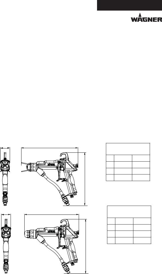
Measurements
B A
C
B_03155
B A
C
GM 5000EAC F with flat jet nozzle
mm inches
A 280 11.02
B 46 1.81
C 264 10.39
GM 5000EAC R with round jet nozzle
mm inches
A 264 10.39
B 46 1.81
C 264 10.39
B_03193
17
GM 5000EAC.
EDITION 03/2012 |
PART NUMBER DOC 2319150 |
OPERATING MANUAL
4.4 FUNCTIONAL DESCRIPTION
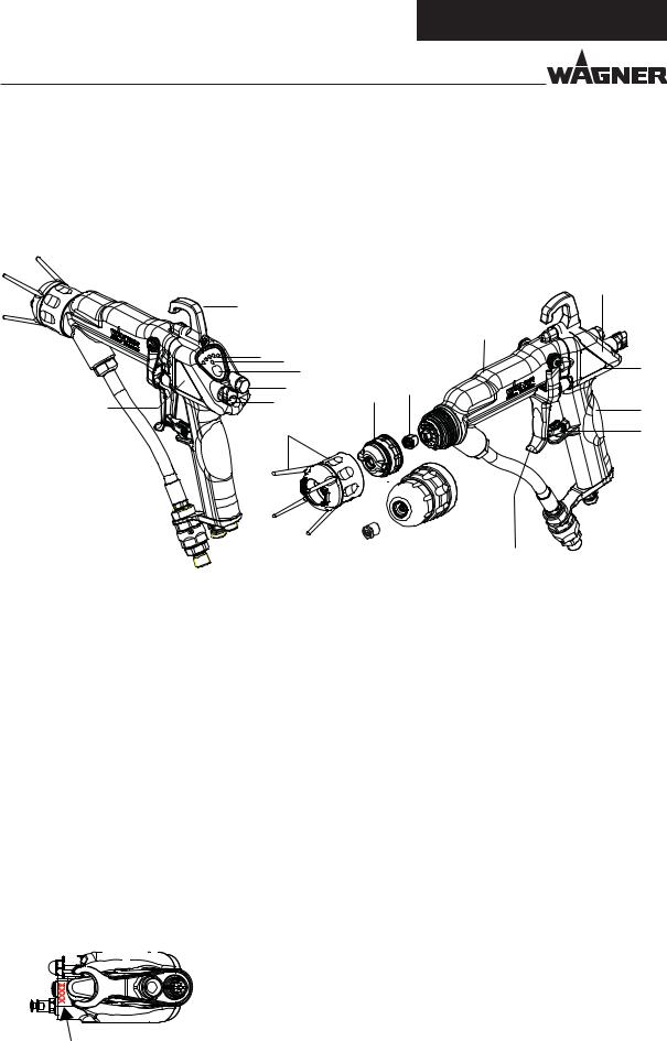
4.4.1 DESIGN OF SPRAY GUN (STANDARD VARIANT)
Note:
The nozzle parts (item 6; 7; 13 and 14) do not belong to the basic equipment of the spray gun.The different versions can be found in Chapter 9„Accessories“.
|
|
|
9 |
|
1 |
|
|
|
|
|
|
|
8 |
|
2 |
3 |
|
22 |
|
|
4 |
|
||
|
15 |
6 |
7 |
|
21 |
16 |
10 |
||
|
||||
|
|
|||
|
5 |
|
11 |
|
20 |
|
|
|
|
|
|
|
|
|
|
|
|
12 |
|||||||||
|
|
|
|
|
|
|
|
|
|
|
|
|
|||||||||||
|
|
|
|
|
|
|
|
|
|
|
|
|
|||||||||||
|
|
|
|
|
|
|
|
|
|
|
|
||||||||||||
|
|
|
|
|
|
|
|
|
|
|
|
|
|
17 |
|
|
|
13 |
|||||
|
|
|
|
|
|||||||||||||||||||
|
|
|
|
|
|
|
|
|
|
|
|
|
18 |
|
14 |
|
B_03156 |
||||||
|
19 |
|
|
|
|
||||||||||||||||||
|
|
|
|
|
|
|
|
||||||||||||||||
Item |
Description |
|
|
Item |
Description |
||||||||||||||||||
1 |
Hook |
|
11 |
Trigger lock |
|||||||||||||||||||
2 |
Display (spray current and recipe) |
|
12 |
Trigger |
|||||||||||||||||||
3 |
Display standby |
|
13 |
Round jet nozzle cap |
|||||||||||||||||||
4 |
Operating button |
|
|
|
(see Accessories chapter 9) |
||||||||||||||||||
|
14 |
Round jet nozzle insert |
|||||||||||||||||||||
|
(standby and recipe change) |
|
|||||||||||||||||||||
|
|
|
|
|
|
|
|
|
|
|
|
|
|
|
|
|
|
|
|
|
(see Accessories chapter 9) |
||
5 |
Protection against contact |
|
|
|
|||||||||||||||||||
|
|
|
|
|
|||||||||||||||||||
|
15 |
Lock plug |
|||||||||||||||||||||
|
with union nut |
|
|||||||||||||||||||||
6 |
Air cap for flat jet nozzle |
|
16 |
Air adjustment |
|||||||||||||||||||
|
(see Accessories chapter 9) |
|
17 |
Electrical cable connection |
|||||||||||||||||||
7 |
ACF 5000 flat jet nozzle |
|
|
|
|||||||||||||||||||
|
18 |
Atomizing air connection |
|||||||||||||||||||||
|
(see Accessories chapter 9) |
|
|
|
|
|
|||||||||||||||||
|
|
19 |
Material connection |
||||||||||||||||||||
8 |
End piece |
|
|||||||||||||||||||||
|
20 |
Filter housing with filter |
|||||||||||||||||||||
|
|
|
|
|
|
|
|
|
|
|
|
|
|
|
|
|
|
|
|||||
9 |
Cover |
||||||||||||||||||||||
|
|
|
|
|
|||||||||||||||||||
|
21 |
Type plate left |
|||||||||||||||||||||
10 |
Handle |
|
|||||||||||||||||||||
|
|
|
|
|
|||||||||||||||||||
|
22 |
Type plate right |
|||||||||||||||||||||
|
|
|
|
|
|
|
|
|
|
|
|
|
|
|
|
|
|
|
|||||
|
|
|
|
|
|
|
|
|
|
|
|
|
|
|
|
|
|
||||||
|
|
|
|
|
|
|
|
|
|
|
|
|
|
|
|
|
|
|
|
|
|
|
|
|
|
|
|
|
|
|
|
|
|
|
|
|
|
|
|
|
|
|
|
|
|
|
|
S |
B_03558 |
Note:
The gun type (T) on the type plate (21) and the serial number (S) on the underside of the handle.
18
GM 5000EAC.
EDITION 03/2012 |
PART NUMBER DOC 2319150 |
OPERATING MANUAL
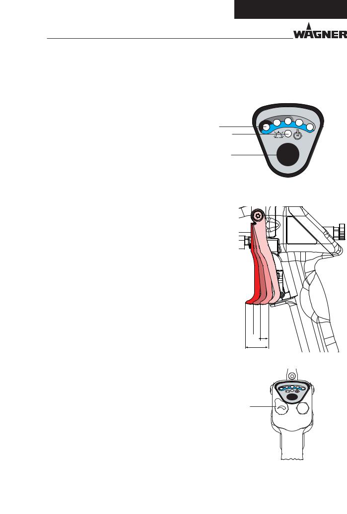
4.4.2 FUNCTIONS OF THE SPRAY GUN
When the spray gun is connected to the control unit and the control unit is switched on, the pre-defined recipe (R1, R2 or R3) is shown on the gun display (2) as
follows. |
|
|
Recipe 1 |
-> ● R1 |
2 |
Recipe 2 |
-> ●●● R2 |
|
Recipe 3 |
-> ●●●●● R3 |
|
Recipe change R1 -> R2 -> R3 -> R1
Press the operating button (4) and hold the button pressed of at least 2 seconds, then it is advanced by 1 recipe.
Display (2) -> ●● = recipe values changed temporarily: The stored recipe values of the previously selected recipe number are re-loaded from memory by pressing the operating button (4) for 2 seconds.
The trigger can be used to activate, one after the other, the various functions of the spray gun.
Distance |
Description |
1 |
AirCoat air opens. |
|
|
2 |
AirCoat air opened and electrostatic (HV) |
|
activated. |
|
-> Display (2) for „spray current“ on the spray |
|
gun ● to ●●●●● activated. |
|
|
3 |
AirCoat air opened and electrostatic (HV) |
|
activated and material valve opened. |
4 |
Max way of trigger. |
|
|
•An increase in the tension needed to pull the trigger back will be felt at the position where the material valve opens.
•For spraying without high-voltage, the high-voltage can be switched off using the operating button (4). Press the operating button (4) briefly: High-voltage is switched off. The standby display (3) illuminates.
3
4
|
R2 |
R1 |
R3 |
B_03182
1
 2
2
 3
3
 4
4
E
|
R2 |
R1 |
R3 |
16
• In the event of a malfunction the spray gun switches to „standby“ operating mode and the display (3) illuminates.
• The width of the spray jet can be adjusted using the air adjustment (16) (only for flat-jet method).
B_03262
19
GM 5000EAC.
EDITION 03/2012 |
PART NUMBER DOC 2319150 |
OPERATING MANUAL
4.5 SPRAYING PROCESS
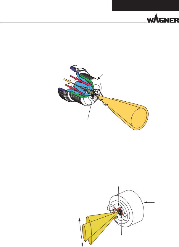
4.5.1 AIRCOAT ROUND JET SPRAY PROCESS
In the AirCoat process, high pressure of 3-15 MPa; 30-150 bar; 435-2176 psi is used to atomize the material. The air at 0-0.25 MPa; 0-2.5 bar; 0-36 psi produces a soft jet.The size of the spray jet can be adjusted by turning the nozzle nut.
Nozzle nut
AirCoat air
Spray material
AirCoat air
"?
Advantages
•High painting capacity
•Low fogging tendency
• |
Good finish |
Multi-channel |
Spray jet |
• |
High viscosity paints can easily be applied |
swirl nozzle |
|
•High endurance of the nozzles
•Change in width the jet
4.5.2. AIRCOAT ATOMIZING FLAT JET SPRAY PROCESS
In the AirCoat process, high pressure of 3-15 MPa; 30-150 bar; 435-2176 psi is used to atomize the material. The AirCoat air at 0-0.25 MPa; 0-2.5 bar; 0-36 psi produces a soft jet, which largely eliminates the problem of overlapping boundaries.There´s a possibility to reduce the jet by form air.
Shaping air
Air cap
Variable spray jet width
B_00020
Atomizing air
Advantages
•High painting capacity
•Low fogging tendency
•Good finish
•High viscosity paints can easily be applied
•High endurance of the AC-nozzles
•Change in width the jet
20
GM 5000EAC.
EDITION 03/2012 |
PART NUMBER DOC 2319150 |
OPERATING MANUAL
4.5.3 ELECTRICAL RESISTANCE
The spray gun produces an electrostatic field by means of the high-voltage electrode. As a result, the particles of paint, which have been atomized by the spray gun, are carried to the earthed object by kinetic and electrostatic energy where they adhere, finely distributed, to the object being sprayed.
Paint particles |
Electrode |
Grounded object
"?
Advantages
•Very high application effectiveness
•Little over spray
•Coating of entire circumferences due to an electrostatic field
•Less working time
21

GM 5000EAC.
EDITION 03/2012 |
PART NUMBER DOC 2319150 |
OPERATING MANUAL
5 START-UP AND OPERATION
5.1 INSTALLATION AND CONNECTION
5.1.1 TYPICAL ELECTROSTATIC SPRAYING SYSTEM
|
|
|
1 |
|
21 |
16 |
2 |
3 |
5 |
15 |
|
4 |
||
|
|
|
|
|
|
14 |
|
|
|
3
R1 |
80 |
|
|
|
60 |
|
|
||
|
100 |
|
||
|
|
|
||
R2 |
40 |
80 |
|
|
20 |
|
|||
|
60 |
|
||
|
|
|
||
R3 |
10 |
40 |
EXT |
|
kV |
||||
|
20 |
|
||
|
|
μA |
|
VM 5000
13
12


 6
6 


 11
11 


10
9
17
7
8
|
B_03158 |
|
|
Item |
Designation |
|
|
1 |
GM 5000EACF spray gun |
|
|
2 |
Gun cable |
3 |
Grounding cable |
|
|
4 |
Pneumatic pumps |
|
|
5 |
Carriage |
6 |
Pressure regulator + |
|
air filter |
|
|
7 |
Material suction system |
|
|
8 |
Return hose |
9 |
High pressure filter |
|
|
18
Item Designation
10Compressed air connection
11Stop valve
12Air pressure regulator
13VM 5000 control unit
14Protective hose
15Air hose
19
20
Item Designation
16Material hose
17Return valve
18Container for the return flow
19Colour container
20Container, cleaning agent
21Mains cable
22
 Loading...