


D |
GB |
F |
I |
|
|
|
® |
Betriebsanleitung |
|
|
|
Operating manual......... |
p. 30 |
|
|
Mode d’emploi |
.............. |
p. 60 |
|
Istruzioni per l’uso........ |
p. 90 |
|
|
Airless Hochdruck-Spritzgerät Airless high-pressure spraying unit Groupe de projection à haute pression
Impianto per la verniciatura a spruzzo ad alta pressione Airless
|
HC 920 • HC 940 • HC 960 |
|
HC 940-SSP • HC 960-SSP |
|
|
Ausgabe 4 / 2011 |
0528100J |
Edition |
|
Edizione |
|
GB
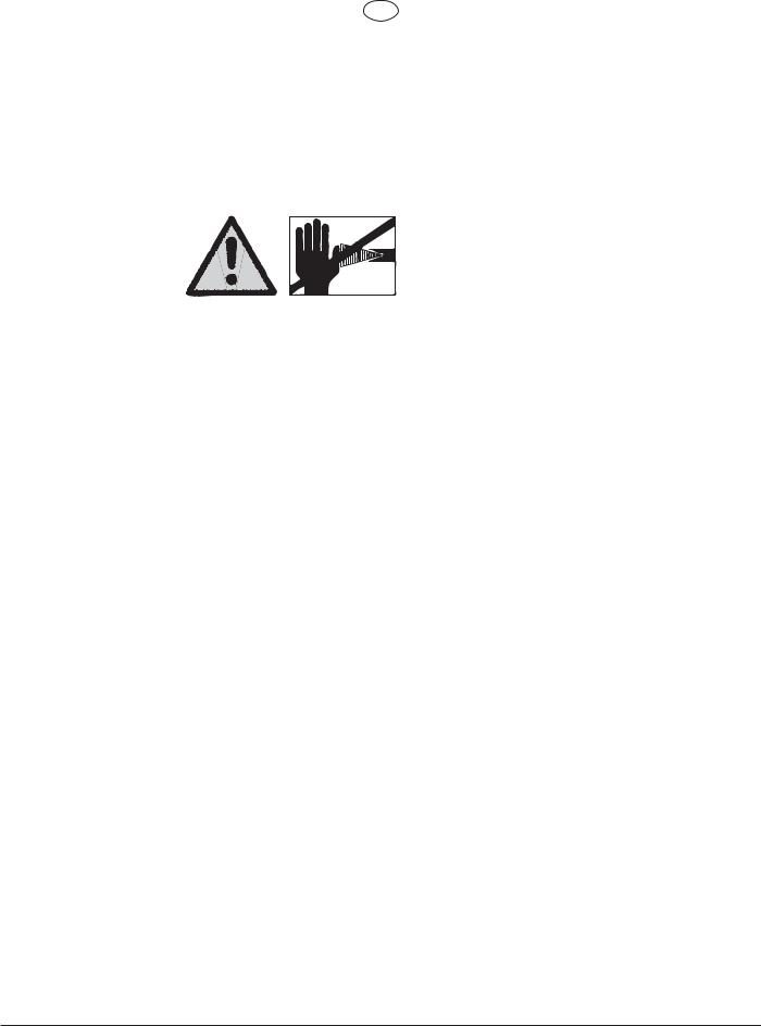
Warning!
Attention: Danger of injury by injection!
Airless units develop extremely high spraying pressures.
& *
. * (-, 1'-* !& *+ & + '* &1 ', * ( *,+ ' , ' 1 !&,' , +(* 1 " ,. * ('!&, , +(* 1 -& , 1'-*+ $ ', * ( *+'&+ '* &!% $+
. * -+ , +(* 1 -& /!, '-, ,!( + ,1 - *' &', ,* , & !&" ,!'& !&"-*1 + *%$ ++ -, & + ' !&"-*1 ,' , +#!& , *'- ' ,!& % , *! $+ '* +'$. &,+ '&+-$, ' ,'* !%% ! , $1 '* )-! # & 0( *, ,* ,% &, & '*% , ' ,'*'-, , ' ,!& % , *! $ '* +'$. &, -+
'( * ,!& !&+,*- ,!'&+ +, , , , , '$$'/!& ('!&,+ %-+,$/ 1+ ' + *. '* +, *,!& -(
-$,1 -&!,+ %-+, &', -+
-* +(* 1 -& -+!& , + ,1 , '& , ,*! *
&+-* , , , -&!, !+ (*'( *$1 *,
# $$'/ $ '( * ,!& (* ++-* ' ! (* ++-* '+ & +(* 1 -&
# $$ '&& ,!'&+ '* $ #+
!&+,*- ,!'&+ * * !& * -$ * $ &!& & % !&, & & ' , -&!, %-+, +,*! ,$1 ' + *.
'* &1 /'*# !+ '& '& , -&!, '* '* . *1 * # !& /'*# ,'$$'/!& *-$ + %-+, ' + *.
$ + , (* ++-* *'% +(* 1 -& & '+
-* , +(* 1 -& -+!& , + ,1 , '& , ,*! *
/!, ' , +'$!& & !&
Be safety-conscious!
30 |
HC 920 • HC 940 • HC 960 |

GB
Contents
Contents |
|
|
|
|
Page |
1. |
Safety regulations for Airless spraying |
.....................32 |
2. |
General view of application......................................... |
33 |
2.1 |
Application...................................................................... |
33 |
2.2 |
Coating materials ........................................................... |
34 |
3. |
Description of unit ....................................................... |
34 |
3.1 |
Airless process............................................................... |
34 |
3.2 |
Functioning of the unit.................................................... |
34 |
3.3 |
Illustration legend for gasoline HC units......................... |
35 |
3.4 |
Illustration of gasoline HC units...................................... |
35 |
3.5 |
Illustration legend for electric HC units........................... |
36 |
3.6 |
Illustration of electric HC units........................................ |
36 |
3.7 |
Technical data for gasoline HC units ............................. |
37 |
3.8 |
Technical data for electric HC units ............................... |
38 |
3.9 |
Transport........................................................................ |
39 |
3.10 |
Transport in vehicle........................................................ |
39 |
3.11 |
Crane transport .............................................................. |
39 |
4. |
Starting operation ........................................................ |
40 |
4.1Swivel mechanism of the material
|
feed pump ...................................................................... |
40 |
4.2 |
Changing the material feed pump position..................... |
40 |
4.3 |
High-pressure hose, |
|
|
spray gun and separating oil.......................................... |
41 |
4.4 |
Gasoline engine (gas units only).................................... |
42 |
4.5 |
Connection to the mains (electric units only) ................. |
42 |
4.6Cleaning preserving agent when starting-up
of operation initially ........................................................ |
42 |
4.7Taking the unit into operation
|
with coating material ...................................................... |
42 |
5. |
Spraying technique...................................................... |
43 |
6. |
Handling the high-pressure hose............................... |
43 |
6.1 |
High pressure hose........................................................ |
43 |
7. |
Interruption of work ..................................................... |
43 |
8. |
Cleaning the unit (shutting down).............................. |
43 |
8.1 |
Cleaning the unit from the outside ................................. |
44 |
8.2 |
Suction filter HC 920 ...................................................... |
44 |
8.3 |
Cleaning the high-pressure filter .................................... |
44 |
8.4 |
Cleaning Airless spray gun ............................................ |
45 |
9. |
Remedy in case of faults............................................. |
46 |
9.1 |
Gasoline engine ............................................................. |
46 |
9.2 |
Electric motor ................................................................. |
46 |
9.3 |
Hydraulic motor.............................................................. |
46 |
9.4 |
Material feed pump ........................................................ |
47 |
10. |
Servicing....................................................................... |
48 |
10.1 |
General servicing ........................................................... |
48 |
10.2 |
Checking the oil level in the hydraulic |
|
|
oil tank............................................................................ |
48 |
10.3 |
Oil and oil filter change of the hydraulic |
|
|
oil pump.......................................................................... |
48 |
10.4 |
High-pressure hose........................................................ |
48 |
|
|
Page |
11. |
Standard equipment of HC units ................................ |
49 |
12. |
Accessories and spare parts ...................................... |
49 |
12.1 |
Accessories for HC units................................................ |
49 |
|
Accessories illustration for HC units............................. |
120 |
12.2 |
Spare parts list for the material feed pump |
|
|
HC 920........................................................................... |
50 |
|
Spare parts diagram for the material |
|
|
feed pump HC 920....................................................... |
121 |
12.3Spare parts list for the material feed pump HC 940 • HC 940-SSP • HC 960 •
|
HC 960-SSP................................................................... |
51 |
|
Spare parts diagram for the material feed |
|
|
pump HC 940 • HC 940-SSP • HC 960 • |
|
|
HC 960-SSP................................................................. |
121 |
12.4 |
Spare parts list for the shovel valve |
|
|
HC 940-SSP • HC 960-SSP........................................... |
51 |
|
Spare parts diagram for the shovel valve |
|
|
HC 940-SSP • HC 960-SSP......................................... |
122 |
12.5 |
Spare parts list for the high-pressure filter ..................... |
52 |
|
Spare parts diagram for the high-pressure |
|
|
filter .............................................................................. |
123 |
12.6 |
Spare parts list for the hydraulic system ........................ |
53 |
|
Spare parts diagram for the hydraulic |
|
|
system..................................................................... |
124/125 |
12.7 |
Spare parts list for units |
|
|
with a gasoline engine.................................................... |
54 |
|
Spare parts diagram for units |
|
|
with a gasoline engine.................................................. |
126 |
12.8 |
Spare parts list for units |
|
|
with an electric motor ..................................................... |
54 |
|
Spare parts diagram for units |
|
|
with an electric motor ................................................... |
127 |
12.9 |
Spare parts list for the carriage...................................... |
55 |
|
Spare parts diagram for the carriage ........................... |
128 |
12.10 |
Electrical schematic HC920 • HC940............................. |
56 |
12.11 |
Electrical schematic HC960 ........................................... |
56 |
13. |
Appendix....................................................................... |
57 |
13.1 |
Selection of tip................................................................ |
57 |
13.2 |
Servicing and cleaning of Airless |
|
|
hard-metal tips ............................................................... |
57 |
13.3 |
Spray gun accessories................................................... |
57 |
13.4 |
Airless tip table............................................................... |
58 |
Sales and service companies................................................ |
59 |
|
Important notes on product liability ................................... |
130 |
|
3+2 years guarantee for professional finishing ................ |
130 |
|
CE Declaration of conformity.............................................. |
134 |
|
HC 920 • HC 940 • HC 960 |
31 |
GB
Safety Regulations
1.Safety regulations for Airless
spraying
All local regulations in force must be observed.
For secure handling of Airless high-pressure spraying units the following safety regulations are to be observed:
Secure the spray gun against unintentional operation
Always secure the spray gun when mounting or dismounting the tip and in case of interruption to work.
Flash point
Only use coating materials with a flash point of 21ºC or above without additional heating.
|
The flash point is the lowest temperature |
Danger |
at which vapours develop from the coating |
|
material. |
These vapours are sufficient to form an inflammable mixture over the air above the coating material.
Explosion protection
Do not use the unit in work places which are covered by the explosion protection regulations.
Danger
Danger of explosion and fire from sources of ignition during spraying work
|
There must be no sources of ignition such as, |
|
for example, open fires, lit cigarettes, cigars or |
|
tobacco pipes, sparks, glowing wires, hot |
Danger |
surfaces, etc. in the vicinity. |
|
Recoil of spray gun
When using a high operating pressure, pulling the trigger guard can effect a recoil force up to 15 N.
|
If you are not prepared for this, your hand can be |
|
Danger |
thrust backwards or your balance lost. This can lead |
|
to injury. |
||
|
Respiratory protection for protection against vapours of solvents
Wear respiratory protection when spraying.
The user must be provided with a breathing mask.
Prevention of occupational illnesses
Protective clothing, gloves and possibly skin protection cream are necessary for the protection of the skin.
Observe the regulations of the manufacturer concerning coating materials, solvents and cleaning agents in preparation, processing and cleaning units.
Max. operating pressure
The permissible operating pressure for the spray gun, spray gun accessories, and high-pressure hose must not fall short of the maximum operating pressure of 22.8 MPa (228 bar).
Danger of injury from the spray jet
Danger
Caution! Danger of injury by injection!
Never point the spray gun at yourself, other persons or animals.
Never use the spray gun without spray jet safety guard.
The spray jet must not come into contact with any part of the body.
In working with Airless spray guns, the high spray pressures arising can cause very dangerous injuries. If contact is made with the spray jet, coating material can be injected into the skin. Do not treat a spray injury as a harmless cut. In case of injury to the skin by coating material or solvents, consult a doctor for quick and correct treatment.
Inform the doctor about the coating material or solvent used.
High-pressure hose (safety note)
Electrostatic charging of spray guns and the high-pressure hose is discharged through the high-pressure hose. For this reason the electric resistance between the connections of the high-pressure hose must be equal to or lower than 1MΩ.
i |
For reasons of function, safety and durability |
use |
only original Wagner high-pressure hoses. |
|
|
|
|
|
Electrostatic charging (formation of sparks or flame)
Under certain circumstances, electrostatic charging can occur on the unit due to the rate of flow of the coating material when spraying. On discharging this
 can result in the emergence of sparks or fire. It is Danger therefore necessary that the unit is always earthed
through the electrical installation. The unit must therefore always be earthed via the carriage frame.
32 |
HC 920 • HC 940 • HC 960 |
|
GB |
Safety regulations |
General view of application |
Installing the unit (gasoline units)
Use the Airless spraying unit with a gasoline engine, preferably outdoors.
|
Take the wind direction into account. Then place |
|
the unit so that no vapors containing solvents are |
Danger |
deposited in the area of the unit. |
Observe a minimum distance of 3 m between the unit with gasoline engine and the spray gun.
Observe a minimum distance of 3 m between the unit with gasoline engine and the spray gun.
Using unit on construction sites (electric units)
Connection to the mains only through a special feed point, e.g. through an error protection insallation with INF < 30 mA
Ventilation when spraying in rooms
Adequate ventilation must be guaranteed in order to remove the solvent vapors and the exhaust fumes of the gasoline engine.
Suctions installations
These are to be set-up by the user of the unit according to local regulations.
Earthing of the object
The object to be coated must be earthed.
Cleaning the unit with solvents
|
When cleaning the unit with solvents, the solvent |
|
should never be sprayed or pumped back into a |
|
container with a small opening (bunghole). An |
Danger |
explosive gas/air mixture can arise. The container |
must be earthed. |
Cleaning the unit
Danger of short-circuits caused by water ingressing into the electrical equipment of the
gasoline engine.
Danger Never spray down the unit with high-pressure or high-pressure steam cleaners.
Work or repairs on the electrical equipment
Only have this work carried out by a qualified electrician. No liability will be taken for incorrect installation.
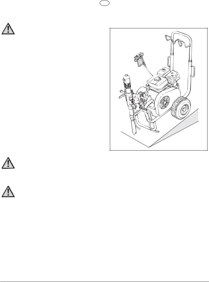
Setting-up on uneven surfaces
The front side of the unit must point downwards to prevent sliding away.
2.General view of application
2.1Application
Priming and final coating of large areas, sealing, impregnation, construction sanitation, façade protection and renovation, rust protection and building protection, roof coating, roof sealing, concrete sanitation, as well as heavy corrosion protection.
Examples of objects to be sprayed
Large-scale construction sites, underground construction, cooling towers, bridges, sewage treatment plants and terraces.
Generally for the whole building protection where operation without electric power is required.
Working on electrical components
Remove the power cord from the socket during all repair work.
HC 920 • HC 940 • HC 960 |
33 |
|
GB |
General view of application |
Description of unit |
2.2Coating materials
Processible coating materials
i |
Pay attention to the Airless |
quality of the coating |
materials to be processed. |
|
|
|
|
|
Dilutable lacquers and paints or those containing solvents, primer and filler, synthetic-resin paints, acrylics, epoxies, latex paints, reactant paints, dispersion paints, fire protection and thick film materials, zinc dust and micaceous iron ore paints, Airless spray primer, sprayable glue and bitumen-like coating materials.
No other materials should be used for spraying without WAGNER’s approval.
HC 940-SSP
With suitable accessories, especially for working with airless spray primer.
HC 960-SSP
Especially suited to working with airless spray primer directly from the container (see accessories).
Filtering
In spite of the high-pressure filter, filtering of the coating material is to be recommended in general.
Stir coating material before commencement of work.
Make sure when stirring with motor-driven
iagitators that no air bubbles are stirred in. Air bubbles disturb when spraying and can, in fact, lead to interruption of operation.
Viscosity
It is possible to work with high-viscosity coating materials with the devices.
If highly viscous coating materials cannot be sucked up, they must be diluted in accordance with the manufacturer’s instruction.
Two-component coating material
The appropriate processing time must be adhered to exactly. Within this time rinse through and clean the unit meticulously with the appropriate cleaning agents.
Coating materials with sharp-edged additional materials
These have a strong wear and tear effect on valves, highpressure hose, spray gun and tip. The durability of these parts can be reduced appreciably through this.
3.Description of unit
3.1Airless process
The main area of application are thick layers of highly viscous coating material for large areas and a high consumption of material.
A piston pump takes in the coating material by suction and conveys it to the tip. Pressed through the tip at a pressure of up to a maximum of 228 bar (22.8 MPa), the coating material is atomised. This high pressure has the effect of micro fine atomisation of the coating material.
As no air is used in this process, it is described as an AIRLESS process.
This method of spraying has the advantages of finest atomisation, cloudless operation and a smooth, bubble-free surface. As well as these, the advantages of the speed of work and convenience must be mentioned.
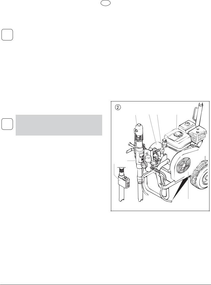
3.2Functioning of the unit
The following section contains a brief description of the technical construction for better understanding of the function.
WAGNER HC 920 • 940 • 960 are high-pressure spraying units driven by either a gasoline engine or electric motor.
The gasoline engine or electric motor (fig. 2, item 1) drives the hydraulic pump (3) by means of a V-belt which is under the belt cover (2). Hydraulic oil flows to the hydraulic motor (4) and then moves the piston up and down in the material feed pump (5).
With devices HC 940-SSP and HC 960-SSP, the piston in the material feed pump moves a shovel valve (6). The shovel valve feeds high-viscosity coating materials.
The inlet valve is opened automatically by the upwards movement of the piston. The outlet valve is opened when the piston moves downward.
The coating material flows under high pressure through the highpressure hose to the spray gun. When the coating material exits from the tip it atomises.
The pressure control valve (7) controls the volume and the operating pressure of the coating material.
|
4 |
3 |
7 |
1 |
6 |
5 |
|
|
|
|
|
|
|
2 |
34 |
HC 920 • HC 940 • HC 960 |

GB
Description of unit
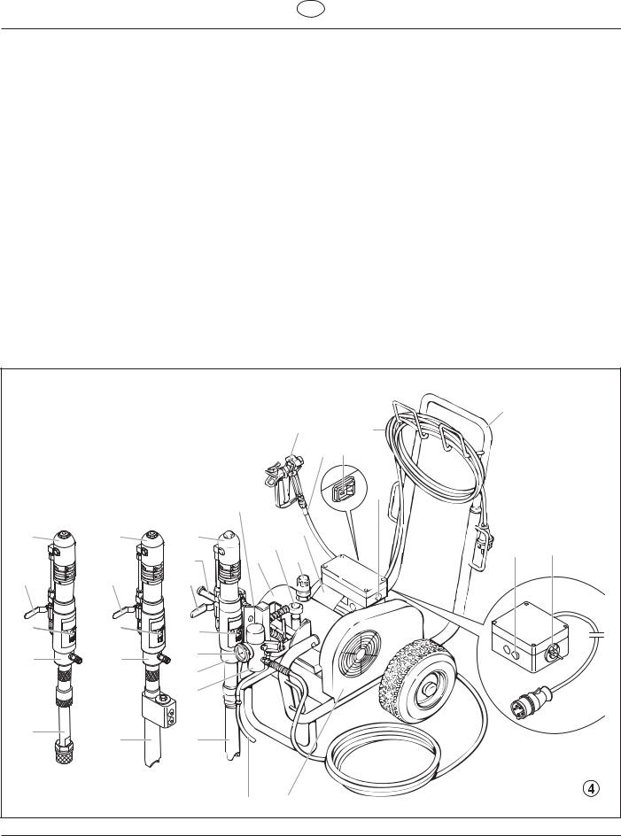
3.3Illustration legend for gasoline HC units
1 |
Spray gun |
13 |
Oil cup for separating oil (separating oil prevents |
|
2 |
High-pressure hose |
|
increased wear and tear of the packings) |
|
14 |
Ball valve horizontal position – |
|||
3 |
Gasoline engine |
|||
|
hydraulic motor switched off |
|||
4 |
Extractable handle |
|
||
|
vertical position – |
|||
5 |
V-belt under the belt cover |
|
||
|
hydraulic motor switched on |
|||
6 |
Return hose |
|
||
15 Handle for swiveling the material feed pump |
||||
7 |
Suction tube |
|||
16 |
Hydraulic motor |
|||
8 |
High-pressure filter |
|||
17 |
Relief valve handle |
|||
9 |
Material feed pump — HC 940, HC 960 |
|||
|
Turn left for circulation & |
|||
10 |
Material feed pump — HC 940-SSP, HC 960-SSP |
|
||
|
Turn right for spray * |
|||
11 |
Material feed pump — HC 920 |
|
||
18 |
Hydraulic oil pump |
|||
12 |
Pressure gauge |
|||
19 |
Pressure control knob |
|||
|
|
|||
|
|
20 |
Oil measuring stick |
|
3.4Illustration of gasoline HC units
|
|
|
1 |
|
|
|
4 |
|
|
|
2 |
|
|
|
3 |
16 |
16 |
16 |
20 |
|
|
18 |
|
|
|
19 |
|
|
|
15 |
|
14 |
14 |
17 |
|
14 |
|
||
|
|
|
|
13 |
13 |
13 |
|
11 |
10 |
12 |
|
9 |
|
||
|
|
|
|
|
|
8 |
|
7 |
7 |
7 |
|
|
|
||
|
|
6 |
5 |
|
|
|
|
HC 920 • HC 940 • HC 960 |
|
|
35 |
GB
Description of unit
3.5Illustration legend for electric HC units
1 |
Spray gun |
16 |
Material feed pump — HC 920 |
|
2 |
High-pressure hose |
17 |
Pressure gauge |
|
3 |
Electric motor |
18 |
Oil cup for separating oil (separating oil prevents |
|
4 |
ON/OFF switch — HC 920, HC 940, HC 940-SSP |
|
increased wear and tear of the packings) |
|
19 |
Ball valve horizontal position – |
|||
5 |
Control lamp that shows unit operational — |
|||
|
hydraulic motor switched off |
|||
|
HC 920, HC 940, HC 940-SSP |
|
||
|
|
vertical position – |
||
6 |
Power cord |
|
||
|
hydraulic motor switched on |
|||
7 |
Extractable handle |
|
||
20 Handle for swiveling the material feed pump |
||||
8 |
Control lamp that shows unit operational — |
|||
21 |
Hydraulic motor |
|||
|
HC 960, HC 960-SSP |
|||
|
22 |
Relief valve handle |
||
9 |
ON/OFF switch (400 V) — HC 960, HC 960-SSP |
|||
|
Turn left for circulation & |
|||
10 |
V-belt under the belt cover |
|
||
|
Turn right for spray * |
|||
11 |
Return hose |
|
||
23 |
Hydraulic oil pump |
|||
12 |
Suction tube |
|||
24 |
Pressure control knob |
|||
13 |
High-pressure filter |
|||
25 |
Oil measuring stick |
|||
14 |
Material feed pump — HC 940, HC 960 |
|||
|
|
|||
15Material feed pump — HC 940-SSP, HC 960-SSP
3.6Illustration of electric HC units
|
|
|
|
|
7 |
|
|
|
|
|
1 |
6 |
|
|
|
|
|
2 |
4 |
|
|
|
|
22 |
|
5 |
|
|
|
|
|
|
|
|
21 |
21 |
21 |
|
3 |
|
|
|
24 |
8 |
9 |
|||
|
|
|
|
|||
|
|
20 |
23 |
25 |
||
|
|
|
|
|||
19 |
19 |
19 |
|
|
|
|
18 |
18 |
18 |
|
|
|
|
16 |
15 |
17 |
|
|
|
|
14 |
|
|
|
|
||
|
|
|
|
|
|
|
|
|
13 |
|
|
|
|
12 |
12 |
12 |
|
|
|
|
|
|
|
|
|
||
|
|
|
11 |
10 |
|
|
|
|
|
|
36 |
HC 920 • HC 940 • HC 960 |
|

GB
|
|
|
|
|
|
Description of unit |
3.7 |
Technical data for gasolline HC units |
|
|
|
|
|
|
|
HC 920 |
HC 940 |
HC 940-SSP |
HC 960 |
HC 960-SSP |
Gasoline engine, power |
|
|
|
|
|
|
3 kW: |
|
|
|
|
|
|
4.1 kW: |
|
|
|
|
|
|
6 kW: |
|
|
|
|
|
|
Max. operating pressure |
|
|
|
|
|
|
22.8 MPa (228 bar): |
|
|
|
|
|
|
Max. volume flow |
|
|
|
|
|
|
5.5 l/min: |
|
|
|
|
|
|
8 l/min: |
|
|
|
|
|
|
12 l/min: |
|
|
|
|
|
|
Volume flow at 12 MPa (120) bar |
|
|
|
|
|
|
5 l/min: |
|
|
|
|
|
|
7.6 l/min: |
|
|
|
|
|
|
11 l/min: |
|
|
|
|
|
|
Max. size of tip with a spray gun |
|
|
|
|
|
|
0.043 inch – 1.10 mm: |
|
|
|
|
|
|
0.052 inch – 1.30 mm: |
|
|
|
|
|
|
0.056 inch – 1.42 mm: |
|
|
|
|
|
|
Max. temperature of the coating material |
|
|
|
|
|
|
43° C: |
|
|
|
|
|
|
Max. Viscosity |
|
|
|
|
|
|
40.000 mPa·s: |
|
|
|
|
|
|
50.000 mPa·s: |
|
|
|
|
|
|
65.000 mPa·s: |
|
|
|
|
|
|
Filter insert (standard equipment) |
|
|
|
|
|
|
5 Maschen: |
|
|
|
|
|
|
0 Maschen: |
|
|
|
|
|
|
Weight |
|
|
|
|
|
|
74 kg |
|
|
|
|
|
|
76 kg |
|
|
|
|
|
|
88 kg |
|
|
|
|
|
|
Hydraulic oil filling quantity |
|
|
|
|
|
|
4.7 l ESSO Nuto H 32: |
|
|
|
|
|
|
max. Reifendruck |
|
|
|
|
|
|
0.2 MPa (2 bar): |
|
|
|
|
|
|
Special high-pressure hose |
|
|
DN 10 mm, 15 m, connection thread NPSM 3/8: |
|
|
DN 13 mm, 15 m, connection thread NPSM 1/2: |
|
|
DN 19 mm, 15 m, connection thread NPSM 3/4: |
|
|
|
|
|
|
|
|
Hose whip |
|
|
|
|
DN 10 mm, 2.5 m, connection thread NPSM 3/8: |
|
|
|
|
Dimensions L x W x H |
|
|
|
|
1160 x 955 x 655 mm: |
|
|
|
|
1185 x 955 x 655 mm: |
|
|
|
|
1200 x 955 x 655 mm: |
|
|
|
|
Max.sound pressure level: |
|
|
|
|
90 dB (A)* |
|
|
|
|
92 dB (A)* |
|
|
|
|
98 dB (A)* |
|
|
|
|
* Place of measurement: 1 m distance from unit and 1.60 m above reverberant floor, 120 bar (12 MPa) operating pressure.
HC 920 • HC 940 • HC 960 |
37 |

GB
Description of unit
3.8Technical data for electric HC units
|
|
HC 920 |
HC 940 |
HC 940-SSP |
HC 960 |
HC 960-SSP |
|
Voltage |
|
|
|
|
|
230 V~, 50 Hz: |
|
|
|
|
|
|
400 V, 50 Hz, V3~: |
|
|
|
|
|
|
Fuse protection |
|
|
|
|
|
|
16 A: |
|
|
|
|
|
|
Power cord |
|
|
|
|
|
|
3 x 2.5 mm2 – 6 m: |
|
|
|
|
|
|
5 x 2.5 mm2 – 6 m: |
|
|
|
|
|
|
Capacity |
|
|
|
|
|
|
3.1 kW: |
|
|
|
|
|
|
5.5 kW: |
|
|
|
|
|
|
Max operating pressure |
|
|
|
|
|
|
22.8 MPa (228 bar): |
|
|
|
|
|
|
|
|
|
|
|
|
|
Maximum volume flow |
|
|
|
|
|
|
5.5 l/min: |
|
|
|
|
|
|
6.6 l/min: |
|
|
|
|
|
|
10 l/min: |
|
|
|
|
|
|
Volume flow at 12 MPa (120 bar) |
|
|
|
|
|
|
4.8 l/min: |
|
|
|
|
|
|
5.2 l/min: |
|
|
|
|
|
|
10 l/min: |
|
|
|
|
|
|
Max. size of tip with a spray gun |
|
|
|
|
|
|
0.043 inch – 1.10 mm: |
|
|
|
|
|
|
0.052 inch – 1.30 mm: |
|
|
|
|
|
|
0.056 inch – 1.42 mm: |
|
|
|
|
|
|
Max. temperature of the coating material |
|
|
|
|
|
|
43° C: |
|
|
|
|
|
|
Max. Viscosity |
|
|
|
|
|
|
40.000 mPa·s: |
|
|
|
|
|
|
50.000 mPa·s: |
|
|
|
|
|
|
65.000 mPa·s: |
|
|
|
|
|
|
Filter insert (standard equipment) |
|
|
|
|
|
|
5 Maschen: |
|
|
|
|
|
|
0 Maschen: |
|
|
|
|
|
|
Weight: |
|
|
|
|
|
|
83 kg |
|
|
|
|
|
|
84.5 kg |
|
|
|
|
|
|
100 kg |
|
|
|
|
|
|
103 kg |
|
|
|
|
|
|
Hydraulic oil filling quantity |
|
|
|
|
|
|
4.7 l ESSO Nuto H 32: |
|
|
|
|
|
|
Max. tire pressure |
|
|
|
|
|
|
0.2 MPa (2 bar): |
|
|
|
|
|
|
Special high-pressure hose |
|
|
DN 10 mm, 15 m, connection thread NPSM 3/8: |
|
|
DN 13 mm, 15 m, connection thread NPSM 1/2: |
|
|
DN 19 mm, 15 m, connection thread NPSM 3/4: |
|
|
|
|
|
|
|
|
Hose whip |
|
|
|
|
DN 10 mm, 2,5 m, connection thread NPSM 3/8: |
|
|
|
|
Dimensions L x W x H |
|
|
|
|
1160 x 955 x 655 mm: |
|
|
|
|
1185 x 955 x 655 mm: |
|
|
|
|
1200 x 955 x 655 mm: |
|
|
|
|
Max. sound pressure level: |
|
|
|
|
77 dB (A)* |
|
|
|
|
80 dB (A)* |
|
|
|
|
88 dB (A)* |
|
|
|
|
* Place of measurement: 1 m distance from unit and 1.60 m above reverberant floor, 12 MPa (120 bar) operating pressure.
38 |
HC 920 • HC 940 • HC 960 |
GB
Description of unit
3.9 |
Transport |
3.11 Crane transport |
Handle
Pull out the handle (fig. 5, item 1) until it will come no further. Push in the snap buttons (2) on the sides of the handle and insert the handle.
Hanging points for crane straps or ropes, see figure 7.
1
2
2
3.10Transport in vehicle
Push locking pin (fig. 6, item 1) in the swivel mechanism (2) for the material feed pump (3) and swivel it to a horizontal position. Ensure that the locking pin locks.
Roll the high-pressure hose over the hose rack on the handle. Secure the unit with a suitable fastening.
1 |
|
2 |
|
3 |
|
HC 920 • HC 940 • HC 960 |
39 |
 Loading...