


 Loading...
PROCOAT™
9155
Airless Paint Sprayer
 Owner’s Manual
Read this manual for complete instructions
Français (page 25) / Español (página 49)
Contents
2 |
Important Safety Information |
14 |
Clean the Inlet Filter |
4 |
What’s in the Box? |
15 |
Short Term Storage |
5 |
Proper Use and Functions |
16 |
Cleanup - latex materials |
6 |
Assembly |
18 |
Cleanup - oil-based materials |
7 |
Pressure Relief Procedure |
19 |
Cleaning the Spray Gun Components |
8 |
Load Material |
20 |
Long-Term Storage |
9 |
Getting Material to Flow |
21 |
Cleaning the Sureflo™ Valve |
10 |
Practice Spraying |
22 |
Troubleshooting |
12 |
Clear the Spray Tip |
72 |
Parts List |
13 |
Clean the Spray Gun Filter |
76 |
Warranty |
0911 • Form No. 0523994C
9195
9175
9145 
Questions?
Call Wagner Technical Service at:
1-800-880-0993
Register your product online at:
www.wagnerspraytech.com
Proper registration will serve as proof of purchase in the event your original receipt becomes misplaced or lost.
Español Français English
ImportantSafety Safety
Information
Read all safety information before operating
the equipment. Save these instructions
Indicates a hazardous situation which, if not avoided, could result in death or serious injury.
a)To reduce the risks of fire or explosion, electrical shock and the injury to persons, read and understand all instructions included in this manual. Be familiar with the controls and proper usage of the equipment.
Grounding Instructions
This product must be grounded. In the event of an electrical short circuit, grounding reduces the risk of electric shock by providing an escape wire for the electric current. This
product is equipped with a cord having a grounding wire with an appropriate grounding plug. The plug must be plugged into an outlet that is properly installed and grounded in accordance with all local codes and ordinances.
warning - Improper installation of the grounding plug can result in a risk of electric shock.
If repair or replacement of the cord or plug is necessary, do not connect the green grounding wire to either flat blade terminal. The wire with insulation having a green outer surface with or without yellow stripes is the grounding wire and must be connected to the grounding pin.
Check with a qualified electrician or serviceman if the grounding instructions are not completely understood, or if you are in doubt as to whether the product is properly grounded. Do not modify the plug provided. If the plug will not fit the outlet, have the proper outlet installed by a qualified electrician.
This product is for use on a nominal 120 volt circuit and has a grounding plug that looks like the plug illustrated below. Make sure that the product is connected to an outlet having the same configuration as the plug. No adapter should be used with this product.
Grounded Outlet
Grounding Pin
Cover for grounded outlet box
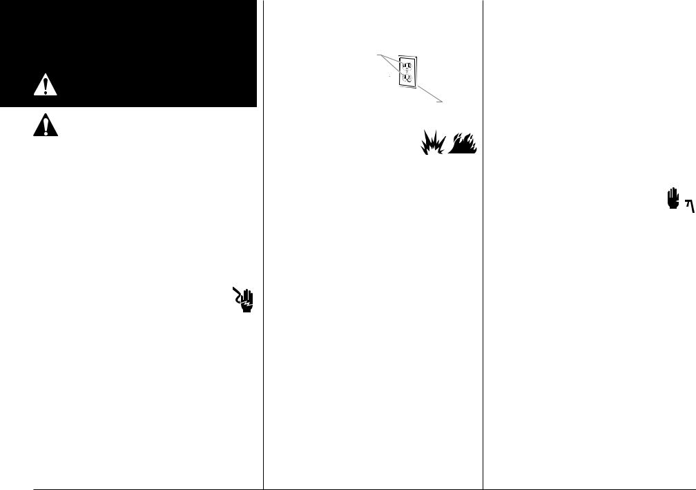
b) WARNING - To reduce the risk of fire or explosion:
1.Do not spray flammable or
combustible materials near an open flame, pilot lights or sources of ignition such as hot objects, cigarettes, motors, electrical equipment and electrical appliances. Avoid creating sparks from connecting and disconnecting power cords.
2.Use extreme caution when using materials with a flashpoint below 70ºF (21ºC). Flashpoint is the temperature that a fluid can produce enough vapors to ignite.
3.Paint or solvent flowing through the equipment is able to result in static electricity. Static electricity creates a risk of fire or explosion in the presence of paint or solvent fumes. All parts of the spray system, including the pump, hose assembly, spray gun and objects in and around the spray area shall be properly grounded to protect against static discharge and sparks. Use only conductive or
grounded high-pressure airless paint sprayer hoses specified by the manufacturer.
4.Verify that all containers and collection systems are grounded to prevent static discharge.
5.Connect to a grounded outlet and use grounded extension cords (electric models only). Do not use a 3 to 2 adapter.
6.Do not use a paint or solvent containing halogenated hydrocarbons. Such as chlorine, bleach mildewcide, methylene chloride and trichloroethane. They are not compatible with aluminum. Contact the coating supplier about compatibility of material with aluminum.
7.Keep spray area well ventilated. Keep a good supply of fresh air moving through the area to keep the air within the spray area free from accumulation of flammable vapors. Keep pump assembly in well ventilated area. Do not spray pump assembly.
8.Do not smoke in the spray area.
9.Do not operate light switches, engines, or similar spark producing products in the spray area.
10.Keep area clean and free of paint or solvent containers, rags, and other flammable materials.
11.Know the contents of the paint and solvents being sprayed. Read all Material Safety Data Sheets
(MSDS) and container labels provided with the paints and solvents. Follow the paint and solvent manufacture’s safety instructions.
12.Place pump at least 25 feet (7.62 meters) from the spray object in a well ventilated area (add more hose if necessary). Flammable vapors are often heavier than air. Floor area must be extremely well ventilated. The pump contains arcing parts that emit sparks and can ignite vapors.
13.Plastic can cause static sparks. Never hang plastic to enclose spray area. Do not use plastic drop cloths when spraying flammable material.
14.Fire extinguisher equipment shall be present and working.
c)WARNING - To reduce the risk of skin injection: 
1.Do not aim the gun at, or spray any person or animal.
2.Keep hands and other body parts away from the discharge. For example, do not try to stop leaks with any part of the body.
3.Always use the nozzle tip guard. Do not spray without the nozzle tip guard in place.
4.Only use a nozzle tip specified by the manufacturer.
5.Use caution when cleaning and changing nozzle tips. In the case where the nozzle tip clogs while spraying, ALWAYS lock gun trigger, shut pump off, and release all pressure before servicing, cleaning tip or guard, or changing tip. Pressure will not be released by turning off the motor. The
PRIME/SPRAY valve or pressure bleed valve must be turned to their appropriate positions to relieve system pressure. Refer to PRESSURE RELIEF PROCEDURE described in the pump manual.
6.Do not leave the unit energized or under pressure while unattended. When the unit is not in use, turn off the unit and relieve the pressure in accordance with the manufacturer’s instructions.
7.High-pressure spray is able to inject toxins into the body and cause serious bodily injury. In the event that injection occurs, seek medical attention immediately.
8.Check hoses and parts for signs of damage, a leak can inject material into the skin. Inspect hose before each use. Replace any damaged hoses or parts.
English |
2 |
|
|
|
|

9.This system is capable of producing 2800 PSI / 193 Bar
(9145) or 3000 PSI / 207 Bar (9155/9175/9195). Only use replacement parts or accessories that are specified by the manufacturer and that are rated a minimum of 3000 PSI. This includes spray tips, nozzle guards, guns, extensions, fittings, and hose.
10.Always engage the trigger lock when not spraying.
Verify the trigger lock is functioning properly.
11.Verify that all connections are secure before operating the unit.
12.Know how to stop the unit and bleed pressure quickly. Be thoroughly familiar with the controls. Pressure will not be released by turning off the motor. The PRIME/
SPRAY valve or pressure bleed valve must be turned to their appropriate positions to relieve system pressure.
Refer to PRESSURE RELIEF PROCEDURE described in the pump manual.
13.Always remove the spray tip before flushing or cleaning the system.
NOTE TO PHYSICIAN:
Injection into the skin is a traumatic injury. It is important to treat the injury as soon as possible. DO
NOT delay treatment to research toxicity. Toxicity is a concern with some coatings injected directly into the blood stream. Consultation with a plastic surgeon or reconstructive hand surgeon may be advisable.
d) WARNING - To reduce the risk of injury:
1.Always wear appropriate gloves, eye protection, clothing and a respirator or mask when painting.
Hazardous vapors – Paints, solvents, insecticides, and other materials can be harmful if inhaled or come in contact with body. Vapors can cause severe nausea, fainting or poisoning.
2.Do not operate or spray near children. Keep children away from equipment at all times.
3.Do not overreach or stand on an unstable support. Keep effective footing and balance at all times.
4.Stay alert and watch what you are doing.
5.Do not operate the unit when fatigued or under the influence of drugs or alcohol.
6.Do not kink or over-bend the hose. Airless hose can develop leaks from wear, kinking and abuse. A leak can inject material into the skin.
7.Do not expose the hose to temperatures or pressures in excess of those specified by manufacturer.
8.Do not use the hose as a strength member to pull or lift the equipment.
9.Use lowest possible pressure to flush equipment.
10.Follow all appropriate local, state and national codes governing ventilation, fire prevention and operation.
11.The United States Government Safety Standards have been adopted under the Occupational Safety and Health Act (OSHA). These standards, particularly part 1910 of the General Standards and part 1926 of the Construction Standards should be consulted.
12.Before each use, check all hoses for cuts, leaks, abrasion or bulging of cover. Check for damage or movement of couplings. Immediately replace hose if any of those conditions exist. Never repair a paint hose. Replace with a conductive high-pressure hose.
13.Do not spray outdoors on windy days.
14.Always unplug cord from outlet before working on equipment (electric models only).
Important Electrical Information
important: Use only a 3-wire extension cord that has a 3-blade grounding plug and a 3-slot receptacle that will accept the plug on the product. Make sure your extension cord is in good condition. When using an extension cord, be sure to use one heavy enough to carry the current your product will draw. An undersized cord will cause a drop in line voltage resulting in loss of power and overheating. A 14
or 12 gauge cord is recommended (see chart). If an extension cord is to be used outdoors, it must be marked with the suffix W-A after the cord type designation. For example, a designation of SJTW-A would indicate that the cord would be appropriate for outdoor use.
Cord gauge |
Maximum cord length |
12 |
150 feet |
14 |
100 feet |
Do not use more than 100 feet of spray hose. If you need to spray further than 100 feet from your power source, use more extension cord, not more spray hose.
If you experience problems with your sprayer at any time during assembly, operation, or cleanup, please refer to the Troubleshooting section of this manual (page 22), or call customer service at:
1-800-880-0993
Specifications:
Capacity:
9145 Up to .29 gallon (1.10 liter) / min 9155 Up to .33 gallon (1.25 liter) / min 9175 Up to .38 gallon (1.40 liter) / min 9195 Up to .42 gallon (1.60 liter) / min
Power source:
9145 1/2 Hp universal motor
9155 5/8 Hp universal motor
9175 3/4 Hp permanent magnet DC motor
9195 7/8 Hp permanent magnet DC motor
Power requirement: 15 amp minimum circuit on 115
VAC, 60 Hz current
Generator power requirement: 5000 Watt
3 |
English |
|

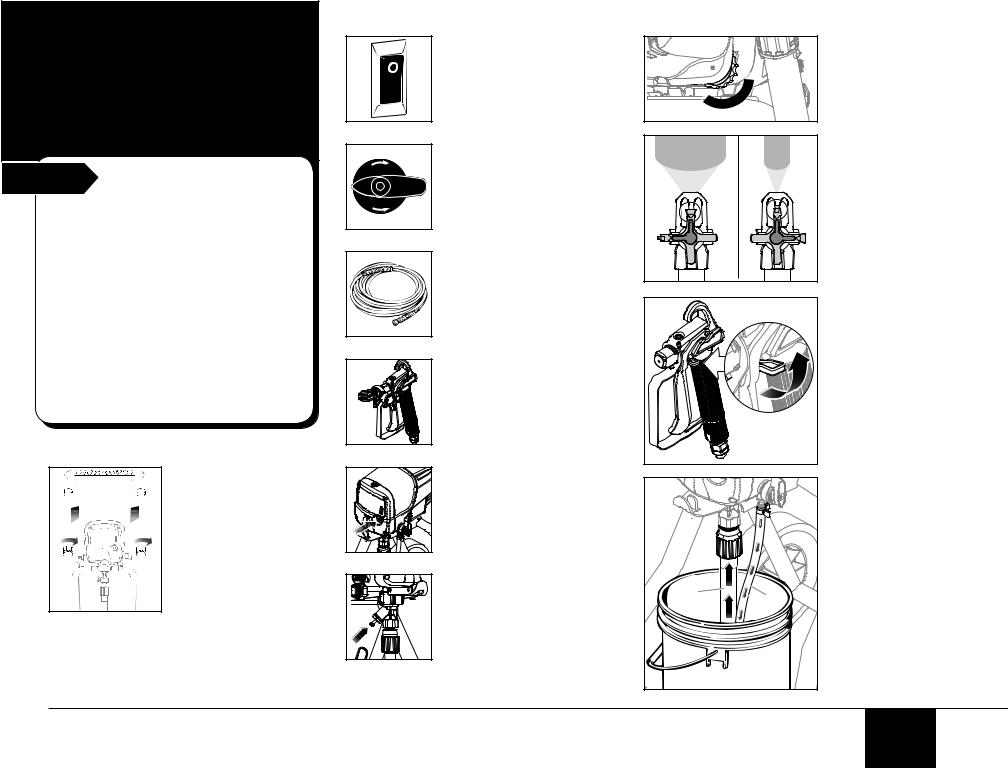
What’s in the box?*
*Certain parts of the sprayer will not be assembled out of the box. Be sure to read Assembly instructions, page 6.
Start Notice:
This pump is available in a stand model (9145) and cart models (9155 shown right, 9175 and 9195). All information given for the stand model applies to the cart model except where indicated.
Some of the graphics in this manual may not exactly match your sprayer and spray gun.
All information and instructions given in this manual applies to all models except where noted.
The type of spray gun and length of spray hose included depends upon the pump model you have. Refer to the chart below for details.
Pump Model |
Gun Model |
Hose Length |
|
|
|
9145 |
GS-07 |
25 ft. |
9155 |
GS-07 |
35 ft. |
9175 |
GS-08 |
50 ft. |
9195 |
GS-08 |
50 ft. |
Spray Gun assembly |
|
Sprayer assembly |
|
|
Pressure control dial |
|
|
(reverse side) |
|
|
Hose wrap* |
GS-07 |
GS-08 |
AutoOiler™ cap* |
|
|
|
|
|
Spray hose port |
Versatip Spray tip assembly |
(reverse side) |
|
|
|
Pump cleaning |
|
|
Spray tip |
adapter |
ON/OFF switch |
|
(reverse side) |
||
|
|
||
|
|
AutoOiler™ |
PRIME/SPRAY |
Spray |
|
button* |
knob |
|
Pail bracket* |
Cord wrap* |
|
guard |
|
Sureflo™ valve |
|
|
|
|
Spray Hose assembly
Suction tube
Material return tube 
Inlet filter 
* Cart models only
|
English |
4 |
|
|
|
|
|
|
Proper use and functions
Start Capability:
Sprays a variety of paints (oil-based and latex), primers, stains, preservatives and other nonabrasive materials.
Do not use!
This pump should not be used with textured materials, block filler, asphalt sealer or materials containing HHC. See coating supplier if flash point is not listed on the container
Safety features:
Spray gun trigger lock and pressure diffuser; built-in tip safety guard; PRIME/SPRAY knob for safe pressure release. Conforms to UL STD
1450. Certified to CAN/CSAC 22.2 NO 68-92
Collapsable handle:
The cart handle can be collapsed for easier storage.
Turn the cart knobs counter-clockwise to unlock the handle.
Turn the cart knobs clockwise to lock the handle into place.
 l
l
SPRAY
PRIME
Controls and Functions
ON/OFF switch:
The ON/OFF switch turns power to sprayer on and off.
(O=OFF, |=ON)
Pressure Control Dial:
The pressure control dial regulates the amount of force the pump uses to push the fluid.
PRIME/SPRAY knob:
The PRIME/SPRAY knob directs material to the material return tube when set to PRIME or to spray hose when set to SPRAY.
Spray hose:
The spray hose connects the spray gun to the pump.
Spray gun:
The spray gun controls the delivery of the material being pumped.
AutoOiler (9155, 9175,
9195 only):
The AutoOiler is designed to provide lubrication to the fluid section of the pump.
Sureflo Valve:
The Sureflo Valve is designed to keep the inlet valve open and from sticking to dried materials.
The Sureflo Valve is activated manually by the user.
|
NARROW |
adjusted based on your spraying |
|
|
VersaTip: |
|
|
The VersaTip spray tip can be |
WIDE |
|
needs. |
GS-07 |
GS-08 |
Trigger lock:
Engage the trigger lock whenever the gun is not in use.
GS-07 / GS-08 - The gun is locked when the trigger lock is at a 90º angle (perpendicular to the trigger in either direction).
(a) |
(b) |
Suction tube (a):
The suction tube draws the fluid from the original container into the pump.
Material return tube (b):
Fluid is sent out through the return tube and back into the original container when the PRIME/SPRAY knob is in the PRIME position.
5 |
English |
|

1. Assembly |
|
Start |
You will need: |
• Two adjustable wrenches
important: Do not plug in the power cord until assembly is complete.
Note: It will be much easier to attach the hose to the sprayer if you uncoil it first.
1 |
1.Insert the ends of the hose bracket into the holes of the handle as shown.
2 |
2.Remove the plug from inside the hose fittings and remove the cap on the outlet valve. Discard both.
3 |
3.Thread one end of the high pressure spray hose to the spray hose port.
4 |
5 |
6 |
7 |
|
(a) |
4.Hold the port with an adjustable wrench, and tighten the hose with the other.
5.Thread the other end of the hose to the spray gun. Hold the gun with one adjustable wrench, and tighten the hose nut with the other.
6.Remove cap from the Sureflo valve (a).
Thread the suction tube onto the inlet valve and tighten firmly by hand.
Note: Be sure that the threads are straight so that the fitting turns freely.
7.Press the return tube onto the return tube fitting.
Squeeze clip over the return tube fitting to secure the return tube.
|
English |
6 |
|
|
|
|
|
|
PressureSafety Relief Procedure*
*Perform when instructed
Start |
Important Safety |
|
Warning |
Be sure to follow the Pressure Relief Procedure when shutting the unit off for any purpose. This procedure is used to relieve pressure from the spray hose. Failure to do so could result in serious injury.
You will need:
• A waste bucket
Important Safety Warning
Be careful when handling the spray gun so you don’t accidently spray yourself. The high pressure paint stream could pierce your skin causing serious injury. If an accident happens see detail procedures in the Safety Information section on pages 2-3. See physician immediately and bring this instruction manual.
1 |
1. Lock the spray gun.
2
SPRAY |
PRIME |
2. Turn the PRIME/SPRAY knob to PRIME.
3 |
4 |
OFF |
O |
3. Turn the power OFF. |
4. Unlock the spray gun. Briefly pull the trigger |
|
to fully relieve pressure from the system. |
|
Lock the spray gun. |
7 |
English |
|

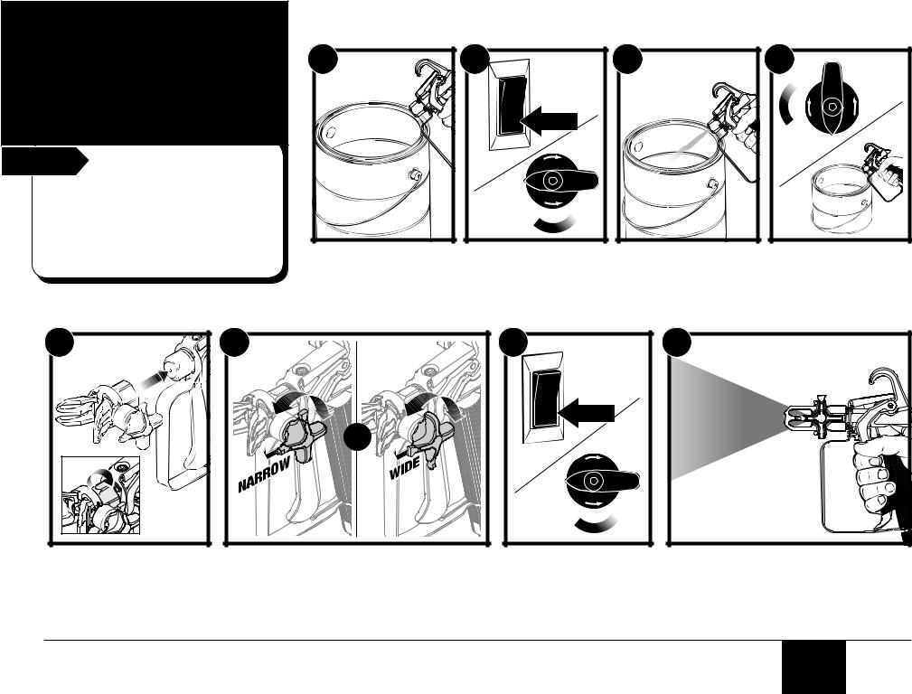
2. Load |
|
Material |
|
Start |
You will need: |
•The material you plan to spray
•Flat blade screwdriver (cart models only)
•Light household oil / Piston Oil™ 
• Extension cord
• Waste bucket
|
Cart Models Only |
1 |
2 |
|
(a) |
1.Remove AutoOiler cap with a flat blade screwdriver.
Squirt Separating Oil into the AutoOiler. Replace cap.
2.Push AutoOiler button 2-5 times to lubricate the fluid section.
Press button 2-3 times before every use. Be sure to check reservoir level (a) and refill as necessary.
4 |
all models |
5 |
(a) |
(b) |
6 |
7 |
|
SPRAY |
ON |
l |
PRIME |
|
Stand model Only |
3 |
3.Squirt a teaspoon of Piston
Oil™ (P/N 0516913, sold separately) into the indicated area.
Light household oil can be substituted if necessary.
8 |
4. Fully depress the |
5. Place a full container |
Sureflo valve to make |
of spraying material |
sure the inlet ball is |
underneath the suction |
free. |
tube (a). |
|
Hold the return tube into a |
|
waste container (b). |
6.Turn the pressure control dial to maximum pressure (+).
Turn the PRIME/SPRAY knob to PRIME.
7.Plug in the sprayer and move the ON/OFF switch to the ON (l) position.
Allow pump to run until you see spray material flowing from the return tube.
8.Switch the pump OFF (O).
Place return tube back into material container and clip return tube and suction tube together.
English |
8 |
|
3. Getting Material to Flow
Start |
You will need: |
•Waste bucket
•Scrap material / cardboard
•Drop cloths to protect floors and furnishings from overspray
Note: Motor will cycle ON and OFF while spraying to regulate pressure. This is normal.
1
1.Point the spray gun into a separate waste container. Unlock the spray gun trigger.
Squeeze and hold trigger for steps 2-3.
2 |
|
l |
ON |
|
2.Turn the power ON.
Turn the PRIME/SPRAY knob to SPRAY.
3
3.Continue to squeeze trigger until the material is flowing freely through the spray gun.
4 |
4.Peform the Pressure Relief Procedure, page 7.
5 |
5.Thread the spray tip guard assembly onto the gun. Tighten by hand.
6 |
OR |
6.Rotate spray tip forward to one of the SPRAY positions.
Unlock the spray gun trigger.
7 |
|
8 |
l |
ON |
SPRAY |
|
||
|
SPRAY |
|
|
PRIME |
|
7.Turn the power ON.
Turn the PRIME/SPRAY knob to SPRAY.
8.Point the spray gun at a piece of scrap material/cardboard.
Pull the trigger and practice spraying
(see pages 10-11).
Note: Motor will cycle ON and OFF while spraying to regulate pressure. This is normal.
9 |
English |
|
Loading...