

Page 1
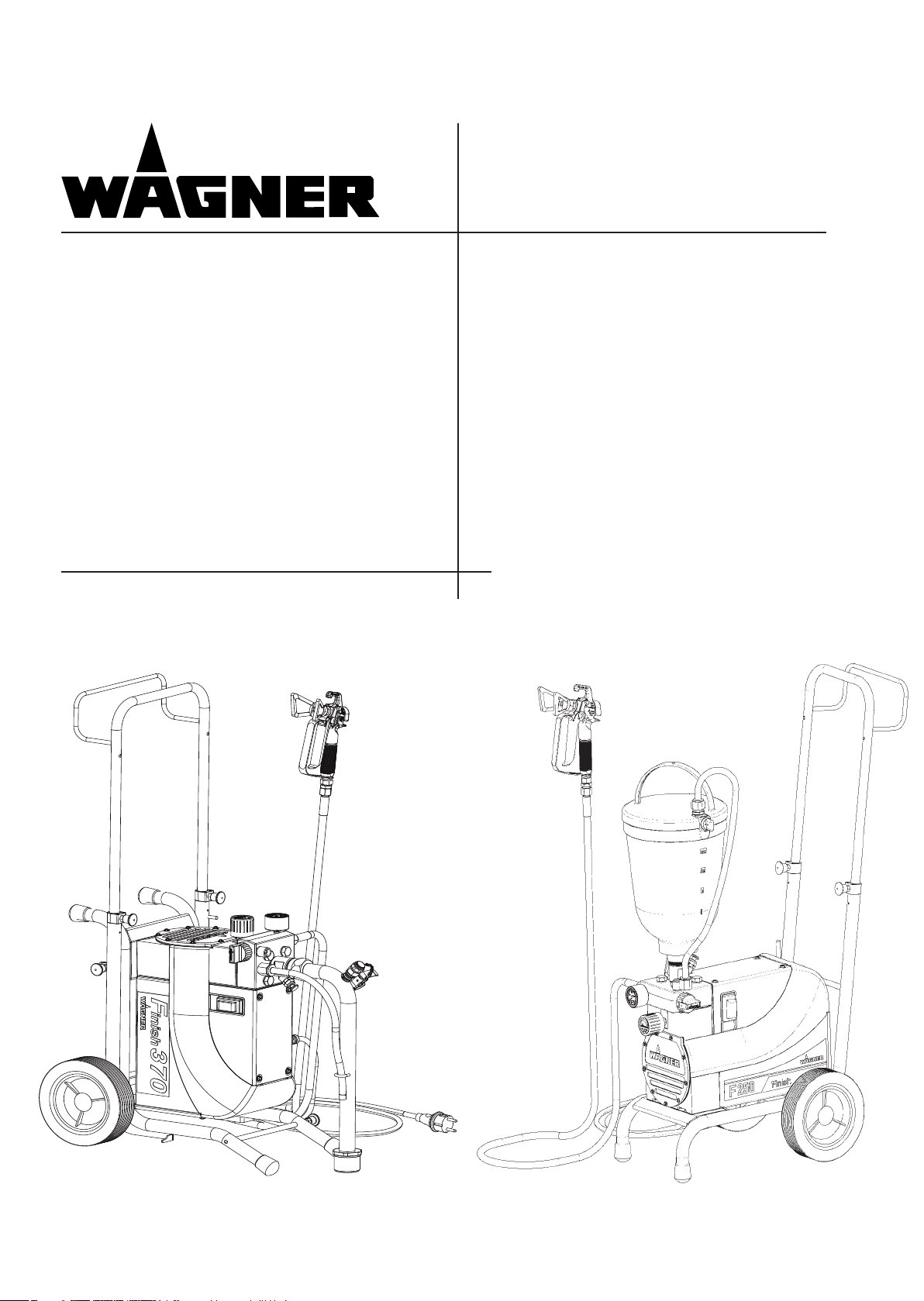
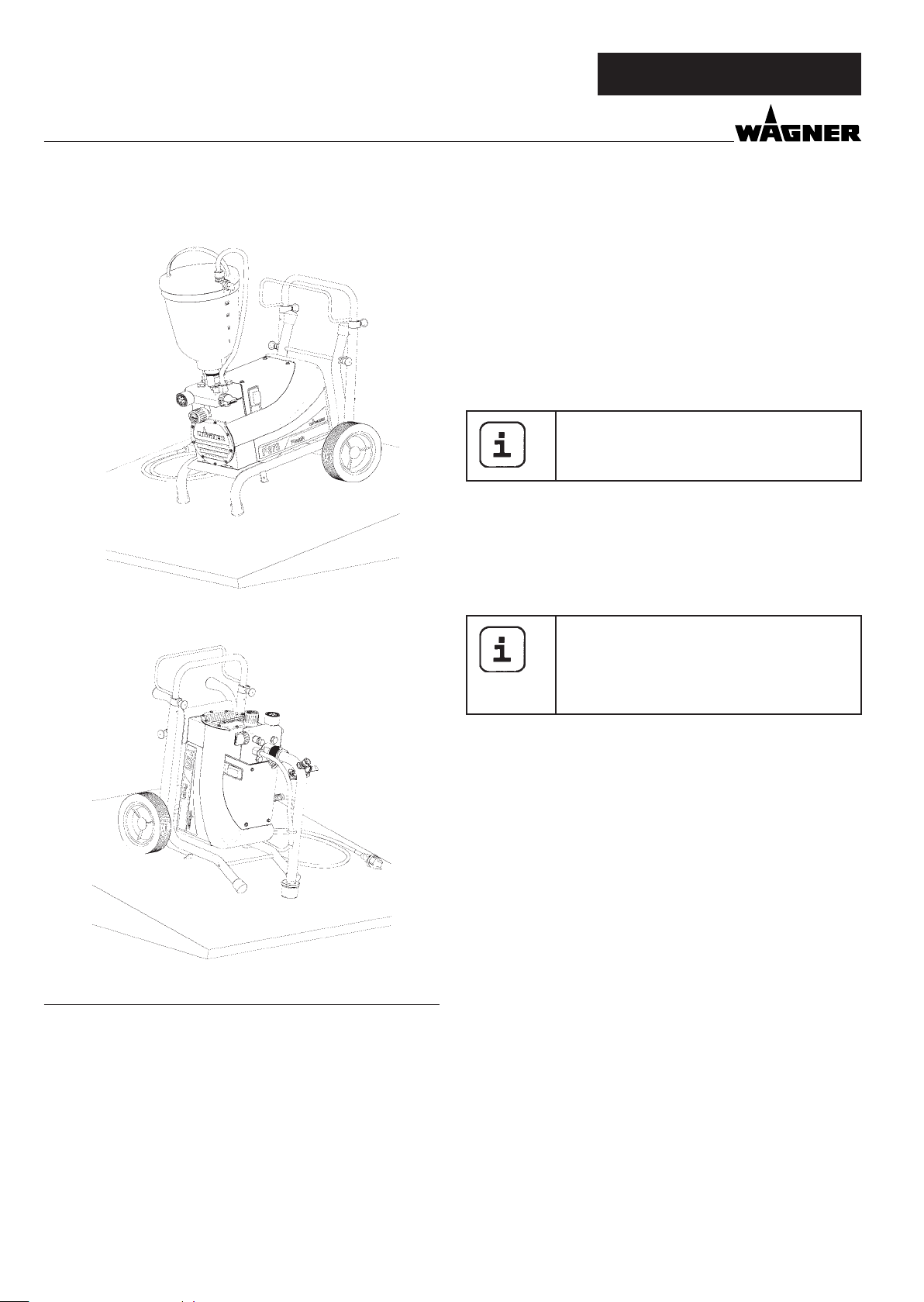
Airless high-pressure spraying unit
Finish 370
Finish 250
Operating manual 2
0252 882
11 / 2007
Finish 370
Finish 250
Page 2
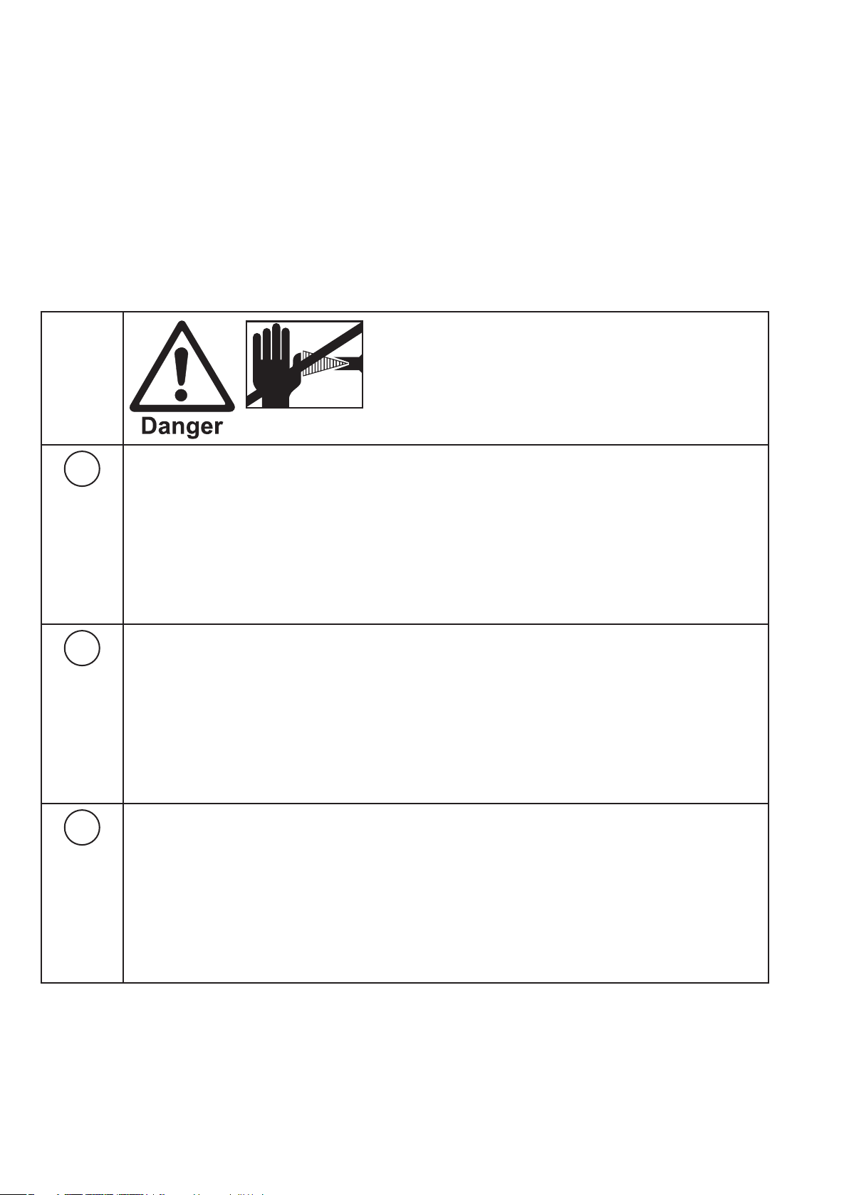
WARNING!
Attention, danger of injury by injection!
Airless units develop extremely high spray pressures.
1
2
3
Never bring ngers, hands or other body parts into contact with the spray jet!
Never point the spray gun at yourself, other persons or animals.
Never use the spray gun without spray jet safety guard.
Do not treat a spray injury as a harmless cut. In case of injury to the skin by coating material
or solvents, consult a doctor for quick and correct treatment. Inform the doctor about the
coating material or solvent used.
The following points are to be observed in accordance with the operating manual
before every start-up:
1. Faulty units may not be used.
2. Secure a Wagner spray gun with the securing lever at the trigger guard.
3. Ensure earthing.
4. Check the permissible operating pressure of the high-pressure hose and spray gun.
5. Check all the connecting parts for leaks.
Instructions for regular cleaning and maintenance of the unit are to be observed
strictly.
Observe the following rules before any work on the unit and at every working
break:
1. Relieve the pressure from the spray gun and high-pressure hose.
2. Secure a Wagner spray gun with the securing lever at the trigger guard
3. Switch the unit o .
Ensure safety!
Page 3

Finish 370 / 250
Contents
GB
CONTENTS
1 SAFETY REGULATIONS FOR AIRLESS SPRAYING 4
1.1 Flash point ___________________________________4
1.2 Explosion protection ___________________________4
1.3 Danger of explosion and re from sources of ignition
during spraying work __________________________4
1.4 Danger of injury from the spray jet _______________4
1.5 Secure spray gun against unintended operation ____4
1.6 Recoil of spray gun ____________________________4
1.7 Breathing equipment as protection against solvent
vapors ______________________________________4
1.8 Prevention of occupational illnesses ______________5
1.9 Max. operating pressure ________________________5
1.10 High-pressure hose (safety instructions) ___________5
1.11 Electrostatic charging (formation of sparks or ames) 5
1.12 Use of units on building sites and workshops _______5
1.13 Ventilation when spraying in rooms ______________5
1.14 Suction installations ___________________________5
1.15 Earthing of the object __________________________5
1.16 Cleaning the unit with solvents __________________5
1.17 Cleaning the unit _____________________________5
1.18 Work or repairs at the electrical equipment ________5
1.19 Work at electrical components ___________________5
1.20 Setup on an uneven surface _____________________6
2 GENERAL VIEW OF APPLICATION _____________ 6
2.1 Application __________________________________6
2.2 Coating material ______________________________6
2.2.1 Coating materials with sharp-edged additional materials __________________________________________6
2.2.2 Filtering _____________________________________6
3. DESCRIPTION OF UNIT ______________________ 7
3.1 Airless process ________________________________7
3.2 Functioning of the unit _________________________7
3.3 Explanatory diagram ___________________________8
3.4 Transportation ________________________________8
3.5 Trolley back tting (only Finish 370) _______________8
3.6 Technical data Finish 250 _______________________9
3.7 Technical data Finish 370 _______________________9
4 STARTUP _________________________________ 10
4.1 Unit with suction system _____________________ 10
4.2 unit with upper hopper (5 litres) _______________ 10
4.3 high pressure hose and spray gun ______________ 10
4.4 Connection to the mains network ______________ 10
4.5 Cleaning preserving agent when starting-up of
operation initially ___________________________ 11
4.6 Ventilate unit (hydraulic system) if the sound of inlet
valve is not audible __________________________ 11
4.7 Taking the unit into operation with coating material 11
5 SPRAYING TECHNOLOGY ___________________ 12
6 HANDLING THE HIGHPRESSURE HOSE _______ 12
6.1 High-pressure hose __________________________ 12
7 INTERRUPTION OF WORK ___________________ 12
8 CLEANING THE UNIT _______________________ 13
8.1 Cleaning the unit from the outside _____________ 14
8.2 Suction lter _______________________________ 14
8.3 High-pressure lter __________________________ 14
8.4 Cleaning the Airless spray gun _________________ 15
9 SERVICING ________________________________ 15
9.1 General servicing ___________________________ 15
9.2 High-pressure hose __________________________ 15
10 REPAIRS AT THE UNIT ______________________ 16
10.1 Inlet valve Pusher ___________________________ 16
10.2 Inlet valve _________________________________ 16
10.3 Outlet valve ________________________________ 16
10.4 Pressure control valve ________________________ 17
10.5 Relief valve ________________________________ 17
10.6 Replacing the diaphragm _____________________ 17
10.7 Replacing the power cable ___________________ 18
10.8 Typical wear parts ___________________________ 18
10.9 Connection diagram _________________________ 19
10.10 Remedy in case of faults ______________________ 20
11 SPARE PARTS AND ACCESSORIES ____________ 21
11.1 Finish 370 / 250 accessories ___________________ 21
11.2 Spare parts list Pump head ___________________ 22
11.3 Spare parts list Pump-Aggregate ______________ 23
11.4 Spare parts list high-pressure lter _____________ 25
11.5 Spare parts List Trolley _______________________ 25
11.6 Spare parts list suction system (rigid) ___________ 26
11.7 Spare parts list hopper 5l _____________________ 27
11.8 Spare parts list hopper with TopClean ___________ 27
CE-declaration ____________________________________28
Service network __________________________________ 29
Testing of the unit ________________________________ 30
Important information on product liability_____________ 30
Guarantee declaration _____________________________ 30
3
Page 4
GB
SAFETY REGULATIONS
Finish 370 / 250
1 SAFETY REGULATIONS FOR
AIRLESS SPRAYING
The safety-speci c requirements for Airless spraying are speci ed in:
a) The European Standard „Spray equipment for coating ma-
terials – safety regulations „ (EN 1953: 1998).
b) The regulations of the German employer‘s liability insu-
rance association („Berufsgenossenschaft“) „Using liquid
jets“ (BGV D15) and „Processing coating materials „ (BGV
D25).
c) Guidelines for construction and implementation require-
ments for liquid jets (spraying units) of the German industrial employer‘s liability insurance association (ZH1/406).
The following safety regulations are to be observed in order
to ensure safe handling of the Airless high-pressure spraying
unit.
.
1.1 FLASH POINT
1.4 DANGER OF INJURY FROM THE SPRAY JET
Attention, danger of injury by injection!
Never point the spray gun at yourself, other
persons or animals.
Never use the spray gun without spray jet
safety guard.
The spray jet must not come into contact
with any part of the body.
In working with Airless spray guns, the high
spray pressures arising can cause very dangerous injuries. If contact is made with the
spray jet, coating material can be injected
into the skin. Do not treat a spray injury as a
harmless cut. In case of injury to the skin by
coating material or solvents, consult a doctor
for quick and correct treatment. Inform the
doctor about the coating material or solvent
used.
1.5 SECURE SPRAY GUN AGAINST UNINTENDED
OPERATION
Only spray coating materials with a ash point
of 21 °C or higher.
The ash point is the lowest temperature at
which vapors develop from the coating material. These vapors are su cient to form an
in ammable mixture over the air above the
coating material.
1.2 EXPLOSION PROTECTION
Do not use the unit in work places which are
covered by the explosion protection regulations.
The unit is not designed to be explosion protected.
1.3 DANGER OF EXPLOSION AND FIRE FROM
SOURCES OF IGNITION DURING SPRAYING
WORK
Always secure the spray gun when mounting or dismounting
the tip and in case of interruption to work.
1.6 RECOIL OF SPRAY GUN
When using a high operating pressure, pulling
the trigger guard can e ect a recoil force up
to 15 N.
If you are not prepared for this, your hand can
be thrust backwards or your balance lost. This
can lead to injury.
1.7 BREATHING EQUIPMENT AS PROTECTION
AGAINST SOLVENT VAPORS
Wear breathing equipment during spraying work.
A breathing mask is to be made available to the user (regulations of the German employer‘s liability insurance association
(„Berufsgenossenschaft“) „Rules for the use of breathing masks“ (BGR 190), „Using liquid jets“ (BGV D15) and „Processing
coating materials „ (BGV D25).
There must be no sources of ignition such as,
for example, open res, lit cigarettes, cigars or
tobacco pipes, sparks, glowing wires, hot surfaces, etc. in the vicinity.
4
Page 5
Finish 370 / 250
GB
SAFETY REGULATIONS
1.8 PREVENTION OF OCCUPATIONAL ILLNESSES
Protective clothing, gloves and possibly skin protection cream
are necessary for the protection of the skin.
Observe the regulations of the manufacturer concerning coating materials, solvents and cleaning agents in preparation,
processing and cleaning units.
1.9 MAX. OPERATING PRESSURE
The permissible operating pressure for the spray gun, spray
gun accessories, unit accessories and high-pressure hose
must not fall short of the maximum operating pressure of 25
MPa (250 bar or 3625 psi).
1.10 HIGHPRESSURE HOSE SAFETY
INSTRUCTIONS
An electrostatic charging of spray guns and the high-pressure
hose is discharged through the high-pressure hose. For this
reason the electric resistance between the connections of the
high-pressure hose must be equal to or lower than 1 MΩ.
Only use WAGNER original-high-pressure
hoses in order to ensure functionality, safety
and durability.
1.14 SUCTION INSTALLATIONS
The are to be provided by the unit user in accordance with the
corresponding local regulations.
1.15 EARTHING OF THE OBJECT
The object to be coated must be earthed.
(Building walls are usually earthed naturally)
1.16 CLEANING THE UNIT WITH SOLVENTS
When cleaning the unit with solvents, the
solvent should never be sprayed or pumped
back into a container with a small opening
(bunghole). An explosive gas/air mixture can
arise. The container must be earthed.
1.17 CLEANING THE UNIT
Danger of short-circuits caused by water ingression!
Never spray down the unit with high-pressure or high-pressure steam cleaners.
1.11 ELECTROSTATIC CHARGING FORMATION OF
SPARKS OR FLAMES
Electrostatic charging of the unit may occur
during spraying due to the ow speed of
the coating material. These can cause sparks
and ames upon discharge. The unit must
therefore always be earthed via the electrical
system. The unit must be connected to an
appropriately-grounded safety outlet.
1.12 USE OF UNITS ON BUILDING SITES AND
WORKSHOPS
The unit may only be connected to the mains network via a
special feeding point with a residual-current device with INF
≤ 30 mA.
1.13 VENTILATION WHEN SPRAYING IN ROOMS
Adequate ventilation to ensure removal of the solvent vapors
has to be ensured.
1.18 WORK OR REPAIRS AT THE ELECTRICAL
EQUIPMENT
These may only be carried out by a skilled electrician. No liability is assumed for incorrect installation.
1.19 WORK AT ELECTRICAL COMPONENTS
Unplug the power plug from the outlet before carrying out
any repair work.
5
Page 6
GB
SAFETY REGULATIONS
1.20 SETUP ON AN UNEVEN SURFACE
The front end must always point downwards in order to avoid
sliding away.
If possible do not use the unit on an inclined surface since the
unit tends to wander through the resulting vibrations.
Finish 370 / 250
Both units are able for all common varnishing jobs like
doors, door frames, balustrades, furniture, woodencladding,
fences, radiators (heating) and steel parts.
2.2 COATING MATERIAL
Diluting lacquers and paints or those containing solvents, twocomponent coating materials, dispersion and latex paints.
No other materials should be used for spraying without
WAGNER‘s approval.
Pay attention to the Airless quality of the coating materials to be processed.
The unit is able to process coating materials with up to
15,000 mPas. If highly viscous coating materials cannot be taken in or the performance of the unit is to low, the paint must
be diluted in accordance with the manufacturer‘s instructions.
Attention: Make sure, when stirring up with
motor-driven agitators that no air bubbles
are stirred in. Air bubbles disturb when spraying and can, in fact, lead to interruption of
operation.
2 GENERAL VIEW OF APPLICATION
2.1 APPLICATION
Finish 370 / 250 is an electric driven unit for the airless atomization of di erent painting materials. Also it is able to feed the
internal feeded paint roller, which is available as accessory.
Finish 370 /250 is made for jobs in the workshop and on the
building site
The unit performance is conceived so that its use is possible
on building sites for small- to middle-area dispersion work.
Finish 250 is designed for varnishing jobs. Small jobs with dispersion work are possible.
2.2.1 COATING MATERIALS WITH SHARPEDGED
ADDITIONAL MATERIALS
These particles have a strong wear and tear e ect on valves
and tips, but also on the heating hose and spray gun. This impairs the durability of these wearing parts considerably.
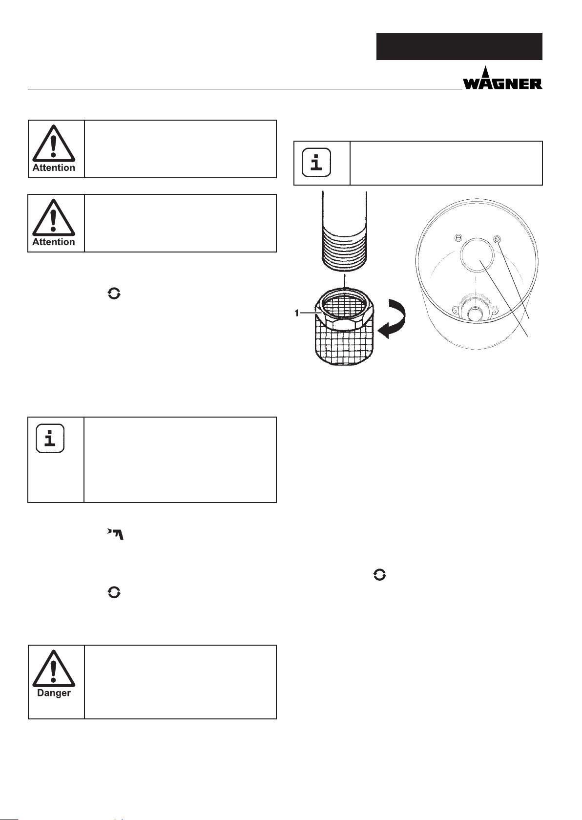
2.2.2 FILTERING
Su cient ltering is required for fault-free operation. To this
purpose the unit is equipped with a suction lter (Item 1) and
an insertion lter in the spray gun (Item 2). Regular inspection
of these lters for damage or soiling is urgently recommended.
A high-pressure lter (Item 3) -available as accessory- is rising
up the ltering surface and will make the work more comfortable.
6
Page 7
Finish 370 / 250
2
3
GB
GENERAL VIEW OF APPLICATION
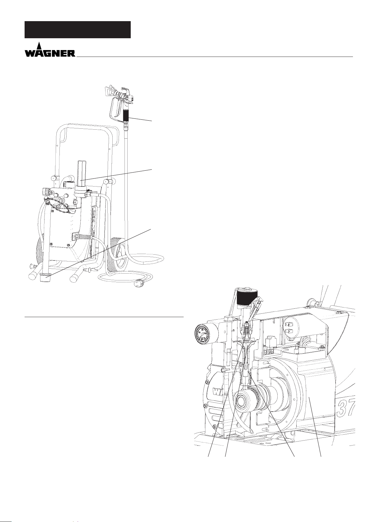
3.2 FUNCTIONING OF THE UNIT
The following section contains a brief description of the technical construction for better understanding of the function:
Finish 370 / 250 is an electrically driven high-pressure paint
spraying equipment.
The motor (Item 1) drives directly the hydraulic pump.
A piston (2) is moved up and down so that hydraulic oil is moved under the diaphragm (3) which then moves.
In detail:
The downwards movement of the machine opens the disk inlet valve (4) automatically and coating material is sucked in.
During the upwards movement of the diaphragm, the coating
material is displaced and the outlet valve opens while the inlet
valve is closed.
1
3. DESCRIPTION OF UNIT
3.1 AIRLESS PROCESS
The main area of application are thick layers of highly viscous
coating material.
At the Finish 370 / 250 unit a diaphragm pump takes in the
coating materials and transports it via a high-pressure hose
to the spray gun with the airless tip. Here the coating material
atomizes since it is pressed through the tip core at a maximum
pressure of 25 MPa (250 bar, 3625 psi). This high pressure has
the e ect of micro ne atomisation of the coating material.
As no air is used in this process, it is described as an AIRLESS
process.
This method of spraying has the advantages of nest atomisation, cloudless operation (depending of a correct unit adjustment) and a smooth, bubblefree surface. As well as these,
the advantages of the speed of work and convenience must
be mentioned.
The coating material ows under high pressure through the
high-pressure hose to the spray gun and is atomized when it
exists from the tip.
The pressure control valve limits the set pressure in the hydraulic oil circuit and thus also the pressure of the coating
material.
A pressure change when the same tip is used also leads to a
change in the amount of paint atomized.
4 3 2 1
7
Page 8
GB
DESCRIPTION OF UNIT
3.3 EXPLANATORY DIAGRAM
1 Tip guard with airless tip
2 Spray gun
3 High-pressure hose
4 Connection for high-pressure hose
5 Pressure gage
6 Pressure control valve
7 Pressure relef valve
Finish 370 / 250
1
2
3
6
Symbols: Spraying
Circulation
8 ON / OFF switch
9 Return tube
10 Suction tube
11 Connection for cleaning with the spray gun
12 Hopper
13 Cleaning ring (TopClean) for hopper (accessory)
14 Inlet valve button
15 Outlet valve
16 Oil measuring stick under the oil screw plug
3.4 TRANSPORTATION
Unroll high-pressure hose and lay it over the shaft.
Pull the locking pins (Item 1) on both sides of shaft. The locking pins can be arrested by a small turn (left or right). Pull
the shaft out and deblock the locking pins. A light pull or push
will help to lock the pins well.
7
8
9
10
9
13
12
14
5
4
15
1 16
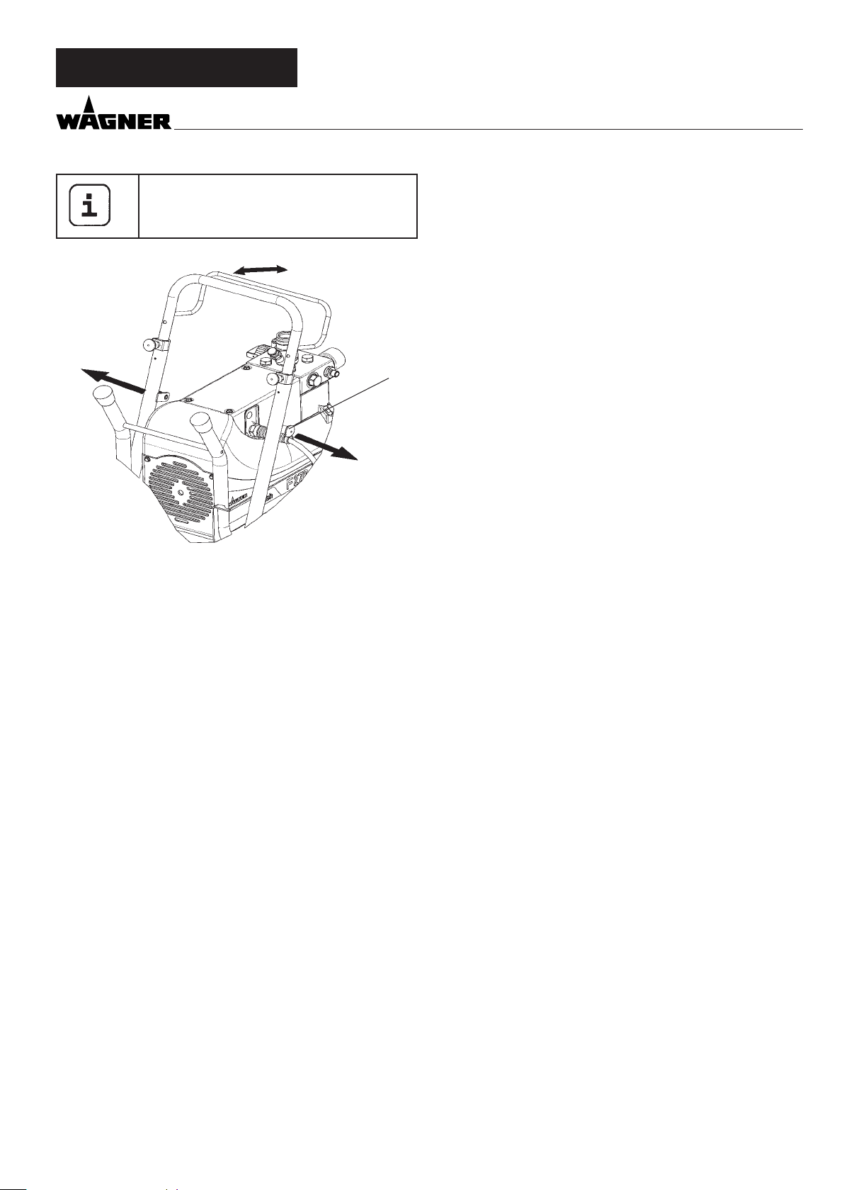
3.5 TROLLEY BACKFITTING ONLY FINISH 370
Transportation in vehicle
Secure the unit in the vehicle by means of suitable fasteners.
8
Pull locking pins (Item 1) on both sides of frame. The locking
pins can be arrested by a small turn (left or right). Move frame
into the other position. Deblock both locking pins so that they
t well in the rest position.
Page 9
Finish 370 / 250
plug of socket, disassemble suction system
and high pressure hose
GB
DESCRIPTION OF UNIT
3.7 TECHNICAL DATA FINISH 370Before start with the back tting, pull of main
Voltage : 230 V AC, 50 Hz
Fuses : 16 A time-lag
Unit connecting line : 6 m long, 3 x 1.5 mm
Max. current consumption
hose heating : 6.0 A
Degree of protection : IP 54
3.6 TECHNICAL DATA FINISH 250
Voltage : 230 V AC, 50 Hz
Fuses : 16 A time-lag
Unit connecting line : 6 m long, 3 x 1.5 mm
Max. current consumption
hose heating : 4,6 A
Degree of protection : IP 54
Acceptance capacity : 1,1 kW
Max. operating pressure : 25 MPa (250 bar)
1
Acceptance capacity : 1.3 kW
Max. operating pressure : 25 MPa (250 bar)
Max. volume ow : 2.9 l/min
Volume ow at 12 MPa
(120 bar) with water : 2.3 l/min
Max. temperature of the
coating material : 43 °C
Max. viscosity : 15,000 mPas
Empty weight pump : 29.5 kg
Hydraulic oil lling
quantity : 0.65 liter
Max. vibration at the spraygun: lower than 2.5 m/s
Max. sound pressure level: 74 dB (A)*
*Place of measurement: 1 m distance from unit and 1.60
m above oor, 12 Mpa (120 bar) operating pressure,
reverberant oor
Max. volume ow : 2.2 l/min
Volume ow at 12 MPa
(120 bar) with water : 1.8 l/min
Max. temperature of the
coating material : 43 °C
Max. viscosity : 15,000 mPas
Empty weight pump : 28 kg
Hydraulic oil lling
quantity : 0.65 liter
Max. vibration at the spraygun: lower than 2.5 m/s
Max. sound pressure level: 74 dB (A)*
*Place of measurement: 1 m distance from unit and 1.60
m above oor, 12 Mpa (120 bar) operating pressure,
reverberant oor
9
Page 10

GB
STARTUP
Finish 370 / 250
4 STARTUP
4.1 UNIT WITH SUCTION SYSTEM
1. Unscrew the dust protective cap (Item 1).
2. Ensure that the sealing surfaces of the connections are
clean.
Ensure that the red inlet (2) is inserted in the coating ma-
terial inlet (5).
3. Use the enclosed 41 mm wrench to screw the union nut
(3) at the suction hose (4) onto the coating material inlet
(5) and tighten it.
4. Screw the union nut (6) at the return hose (7) to the connection (8) (22mm).
4.2 UNIT WITH UPPER HOPPER 5 LITRES
1. Unscrew the dust protective cap (Item 1).
2. Ensure that the sealing surfaces of the connections are
clean.
Ensure that the red inlet (2) is inserted in the coating ma-
terial inlet (5).
3. Screw the union nut (6) on the return pipe (7) onto the
connection (8).
3. Hang the return pipe (7) into the hopper and screw the
upper hopper (9) onto the coating material inlet (5).
if using hopper with cleaning ring (TopClean) step 5 and 6
5. Fix TopClean on hopper upside
6. Plug in return pipe into TopClean and screw on union nut
4.3 HIGH PRESSURE HOSE AND SPRAY GUN
1. Screw the high pressure hose (10) onto the hose connection
2. Screw the spray gun (11) onto the high pressure hose
3. Tighten all union nuts on high pressure hose so that no
coating material can escape.
4. Screw the tip holder with the selected tip onto the spray
gun, align tip and tighten union nut.
When unscrewing the high pressure hose,
hold rmly on the hose connection with a
22mm wrench.
4.4 CONNECTION TO THE MAINS NETWORK
Connection must always be carried out via
an appropriately grounded safety outlet with
residual-current-operated circuit-breaker.
Before connecting the unit to the mains supply, ensure that
the line voltage matches that speci ed on the unit’s rating
plate.
11
10
9
8
7
6
1
3
2
5
8
7
4
10
Page 11

Finish 370 / 250
4.5 CLEANING PRESERVING AGENT WHEN
STARTINGUP OF OPERATION INITIALLY
Unit with suction tube
1. Immerse the suction system into a container lled with a
suitable cleaning agent (recommendation: water).
Unit with hopper
2. ll up hopper with a suitable cleaning agent (recommendation: water).
3. Switch on unit.
4. Turn the pressure regulating knob (1) to the right until
the stop is reached.
5. Open relief valve (2)
valve position (circulation)
6. Wait until cleaning agent is emitted from the return hose.
7. Turn the pressure regulating knob (1) back approx. one
rotation.
8. Close relief valve (2)
valve position (spraying), pressure is rising up inside
the high pressure hose (visble at pressure gage)
9. Point the tip of the spray gun into an open collecting container and pull the trigger guard at the spray gun.
10. The pressure is increased by turning the pressure regulating knob (1) to the right. Set approx. 10 MPa at the pressure gage.
11. Spray the cleaning agent out of the unit for approx.
1 - 2 min. (~5 liters) into the open collecting container.
GB
STARTUP
4
3
1
2
4.7 TAKING THE UNIT INTO OPERATION WITH
COATING MATERIAL
4.6 VENTILATE UNIT HYDRAULIC SYSTEM IF THE
SOUND OF INLET VALVE IS NOT AUDIBLE
1. Switch on the unit.
2. Turn pressure regulating knob (1) three revolutions to
the left.
3. Open relief valve (2)
valve position (circulation)
The hydraulic system is ventilated. Leave the unit on for
two or three minutes.
4. Then turn pressure regulating knob (1) to the right until
stop.
5. Press inlet valve pusher (4).
Sound of the inlet valve is audible.
6. If not, repeat points 2 and 4
Unit with suction tube
1. Immerse the suction system into a container lled with
coating material.
Unit with hopper
2. ll coating material into the hopper.
3. Press inlet valve pusher (4) several times to release possibly clogged inlet valve
4. Open relief valve (2)
valve position (circulation)
5. Switch on unit.
6. Turn the pressure regulating knob (1) to the right until
the stop is reached.
When the noise of the valves changes, the unit is bled and
takes in coating material.
7. If coating material exits from the return hose, turn the
pressure regulating knob (1) back approx. 1 rotation.
8. Close relief valve (2)
valve position (spraying), pressure is rising up inside
the high pressure hose (visble at pressure gage (3))
9. Pull of the spray gun and spray into an open collecting
container in order to remove the remaining cleaning
agent from the unit. When coating materials exits from
the tip, close the spray gun.
10. Pull of the spray gun and adjust the spraying pressure by
turning the pressure regulating knob (1).
11. The unit is ready to spray.
11
Page 12

GB
SPRAYING TECHNIQUE / HANDLING THE HIGH-PRESSURE HOSE / INTERRUPTION OF WORK
Finish 370 / 250
5 SPRAYING TECHNOLOGY
Move the spray gun evenly during the spraying process. If this
is not observed, an irregular spraying appearance will be the
result. Carry out the movement with the arm, not with the
wrist. A parallel distance of approx. 30 cm between the tip and
the surface to be coated should always be observed. The lateral limitation of the spray fan should not to be too distinct. The
edge of spraying should be gradual to facilitate overlapping of
the next coat. The spray gun should always be held at an angle
of 90° to the surface to be coated. A spray fan aimed obliquely
at the surface to be coated leads to an unwanted spray cloud.
To achieve perfect surfaces at varnishing works, special accessories are available at Wagner, e.g. FineFinish tips or an AirCoat
gun set. Your Wagner dealer will advise you.
6 HANDLING THE HIGHPRESSURE
HOSE
The high-pressure hose is to be handled with care. Avoid sharp
bending or kinking. The smallest bending radius amounts to
about 20 cm.
Do not drive over the high-pressure hose. Protect against
sharp objects and edges.
7 INTERRUPTION OF WORK
1. Turn pressure regulating knob three revolutions to the
left.
2 Open relief valve (2)
valve position (circulation)
3. Switch o the unit
4. Pull trigger guard of spray gun to decrease the pressure of
the high pressure hose and the spray gun.
5. Secure the spray gun, refer to the operating manual of the
spray gun.
6. Remove tip from tip holder and store the tip in a small vessel with suitable cleaning agent.
7. Leave the suction system immersed in the coating material or immerse it in the corresponding cleaning agent. The
suction lter and unit should not dry out.
8. Cover the material container in order to prevent the paint
from drying.
In using quick-drying or two-component
coating materials, do not fail to rinse unit
through with a suitable cleaning agent during the processing period.
Danger of injury through leaking highpressure hose. Replace any damaged highpressure hose immediately.
Never repair defective high-pressure hoses
yourself!
When using the high-pressure hose while
working on sca olding, it is best to always
guide the hose along the outside of the scaffolding.
6.1 HIGHPRESSURE HOSE
The unit is equipped with a high-pressure hose specially suited for diaphragm pumps.
Only use WAGNER original-high-pressure
hoses with internal heating in order to ensure
functionality, safety and durability.
12
Page 13

Finish 370 / 250
GB
DISPLAYS AT THE UNIT / CLEANING THE UNIT
8 CLEANING THE UNIT
A clean state is the best method of ensuring operation without problems. After you have nished spraying, clean the
unit. Under no circumstances may coating material rests dry
and harden in the unit. The cleaning agent used for cleaning
(only with a ash point above 21 °C) must be suitable for the
coating material used.
• Secure the spray gun, refer to the operating manual of
the spray gun.
Remove and clean the tip.
• Unit with suction system
1. Open relief valve
valve position (circulation) and switch on unit
2. Remove suction tube from the material container, the return tube remains over the material container.
3. Immerse the suction system into a container lled with a
suitable cleaning agent
4. Turn the pressure control valve back in order to set a minimal spraying pressure.
5. Close relief valve,
valve position (spraying)
6. Pull the trigger guard of the spray gun in order to pump
the remaining coating material from the suction hose,
high-pressure hose and the spray gun into an open container (if appropriate, increase the pressure at the pressure control valve slowly in order to obtain a higher material
ow).
The container must be earthed in case of
coating materials which contain solvents.
14. Rinse in the circuit – Open relief valve
valve position (circulation).
15. Close the spry gun.
16. When cleaning with water repeat the procedure about 3
minutes long with clear water.
17. Remove spray gun from suction tube, close spray gun
connection at suction tube with closure nut.
The cleaning e ect is increased by alternatively opening and closing the spray gun.
Caution! Do not pump or spray in container
with small opening (bunghole)!
See safty regulations.
7. Open relief valve
valve position (circulation)
8. Pump suitable cleaning agent in the circuit for several minutes.
with in exible suction system (tube) step 9 up to 17
9. Screw the spray gun to the suction tube with both enclosed 22 mm wrenches.
10. Pump a suitable cleaning agent in the circuit for about
1 minute.
11. Pull the trigger guard of the spray gun and lock it with a
clamp.
12. Close relief valve,
valve position (spraying)
13. Clean the suction tube about 3 minutes long.
18. Close relief valve,
valve position (spraying)
19. Pump the remaining cleaning agent into an open container until the pump is empty.
20. Switch o the unit
Warm water improves the cleaning e ect in
the case of water-dilutable coating materials.
• Unit with upper hopper
1. Open relief valve
valve position (circulation) and switch on unit
2. Turn the pressure control valve back in order to set a minimal spraying pressure.
3. Close relief valve,
valve position (spraying)
4. Pull the trigger guard of the spray gun in order to pump
the remaining coating material from the hopper, highpressure hose and the spray gun into an open container (if
appropriate, increase the pressure at the pressure control
valve slowly in order to obtain a higher material ow).
13
Page 14
GB
CLEANING THE UNIT
Finish 370 / 250
The container must be earthed in case of
coating materials which contain solvents.
Caution! Do not pump or spray in container
with small opening (bunghole)!
See safty regulations.
5. Fill up hopper with suitable cleaning agent.
6. Open relief valve
valve position (circulation)
7. Pump suitable cleaning agent in the circuit for several minutes.
with cleaning ring (TopClean) step 8 up to 12
8. Switch reverser knob into a horizontal position.
The cleaning agent will ow around the circumference of
the inner hopper wall and will clean it in some minutes,
depending of the fouling
9. Switch reverser knob into the upright position.
Cleaning agent is owing directly into the hopper
Do not switch the reverser knob at the cleaning ring into the horizontal position when
the pump is load with coating material. The
devider holes can be plugged.
Than the cleaning work of cleaning ring is
reduced, and it will take more time up to the
cleaning ring has cleaned themself.
10. Close relief valve,
valve position (spraying)
11. Pump the remaining cleaning agent from the hopper,
high-pressure hose and the spray gun into an open container
12. Open relief valve
valve position (circulation)
13. Switch o unit
8.1 CLEANING THE UNIT FROM THE OUTSIDE
First unplug the power plug from the outlet.
Danger of short-circuits caused by water
ingression! Never spray down the unit with
high-pressure or high-pressure steam cleaners.
Wipe down unit externally with a cloth which has been immersed in a suitable cleaning agent.
8.2 SUCTION FILTER
Clean lters always ensure maximum volume,
constant spray pressure and problem-free
functioning of the unit.
2
1
suction tube 5l hopper
Unit with suction system
1. Unscrew the lter (Item 1) from the suction tube.
2. Clean or replace the lter.
Carry out cleaning with a hard brush and a corresponding
cleaning agent.
Unit with hopper
1. Release screws with a screwdriver (Item 2).
2. Lift and remove lter disk with a screwdriver
3. Clean or replace the lter disk.
Carry out cleaning with a hard brush and a corresponding
cleaning agent.
8.3 HIGHPRESSURE FILTER
1. Open relief valve
valve position (circulation) - Switch the unit o .
2. Open the high-pressure lter and clean the lter insert. To
do so:
3. Unscrew the lter housing (1) by hand.
4. Remove the lter insert (2) and pull out the bearing spring
(3).
5. Clean all the parts with the corresponding cleaning agent.
If compressed air is available – blow through the lter insert and bearing spring.
6. When mounting the lter ensure that the bearing ring (4)
in the lter insert is positioned correctly and check the Oring at the lter housing for damage.
7. Screw on the lter housing by hand until it stops (a higher
tightening force only impedes later dismantling).
14
Page 15

Finish 370 / 250
8.4 CLEANING THE AIRLESS SPRAY GUN
1. Rinse the Airless spray gun with a suitable cleaning agent
under lower operating pressure.
2. Clean the tip thoroughly with a suitable cleaning agent so
that no suitable coating material rests remain.
3. Do not store the tip in solvent because this reduces the
durability considerably.
4. Clean the outside of the Airless spray gun thoroughly.
GB
CLEANING THE UNIT / SERVICING
9 SERVICING
9.1 GENERAL SERVICING
An annual expert check is higly recomended
to be sure to have an safe unit
You can servicing of the unit carried out by
the Wagner Service. Favorable conditions can
be agreed with a service agreement and/or
maintenance packages.
Minimum check before every startup:
1. Check the high-pressure hose, spray gun with rotary joint,
power supply cable with plug for damage.
2. Check whether the pressure gage can be read.
1
3
2
Insertion lter in the Airless spray gun
Removal
1. Pull the protective bracket (1) forwards.
2. Screw the grip (2) out of the gun housing. Pull out the insertion lter (3).
3. If the insertion lter is clogged or defective, replace it.
check at periodical intervals:
1. Check inlet-, outlet-, relief valve according wear. Clean it
and replace worn out parts.
2. Check all lter inserts (spray gun, suction system) clean it
and replace if necessary.
9.2 HIGHPRESSURE HOSE
Inspect the high-pressure hose visually for any notches or
bulges, in particular at the transition in the ttings. It must be
possible to turn the union nuts freely. A conductivity of less
than
1 MΩ must exist across the entire length.
Have all the electric tests carried by the Wagner Service.
Installation
1. Slide the insertion lter (3) with the longer cone into the
gun housing.
2. Screw the grip (2) into the gun housing and tighten it.
3. Latch in the protective bracket (1).
15
Page 16

GB
REPAIRS AT THE UNIT
Finish 370 / 250
10 REPAIRS AT THE UNIT
Switch the unit o .
Before all repair work: Unplug the power
plug from the outlet.
10.1 INLET VALVE PUSHER
1. Use a 17 mm spanner to screw out the inlet valve button.
2. Replace the wiper (1) and O-ring (2).
2
1
Installation
1. Insert the inlet valve (2) into the trigger housing (1) and
secure with the clasp (3). Ensure that the (black) seal (5) is
mounted in the trigger housing.
2. Screw the unit from the trigger housing and the inlet valve into the paint section. The same (black) seal (7) has to
be mounted in the paint section.
3. Tighten the trigger housing with the 30 mm wrench and
tighten with three light blows of the hammer on the end
of the wrench. (Corresponds to approx. 90 Nm tightening
torque).
3
1
5
10.2 INLET VALVE
1. Place the enclosed 30 mm wrench on the trigger housing
(1).
2. Loosen the trigger housing (1) with light blows of a hammer on the end of the wrench.
3. Screw out the trigger housing with the inlet valve (2) from
the paint section.
4. Pull of the clasp (3) using the enclosed screwdriver.
5. Place the enclosed 30 mm wrench on the inlet valve (2).
Turn out the inlet valve carefully.
6. Clean the valve seat (4) with a cleaning agent and brush
(ensure that no brush hairs are left behind).
7. Clean the seals (5, 6) and check for damage. Replace, if necessary.
8. Check all the valve parts for damage. In case of visible
wear replace the inlet valve.
2
4
6
10.3 OUTLET VALVE
1. Use a 22 mm wrench to screw the outlet valve from the
paint section.
2. Carefully pull of the clasp (1) using the enclosed screwdriver. The compression spring (2) presses ball (4) and valve
seat (5) out.
3. Clean or replace the components.
4. Check the O-ring (7) for damage.
5. Check the installation position when mounting the spring
support ring (3) (clipped onto spring (2)), outlet valve seat
(5) and seal (6), refer to gure.
16
Page 17

Finish 370 / 250
GB
REPAIRS AT THE UNIT
10.5 RELIEF VALVE
Replace a fault re ef valve (1) as a single unit.
Only the O-ring (2) may be replaced as a single part
564
10.4 PRESSURE CONTROL VALVE
Only have the pressure control valve (1) replaced by the customer service.
The max. operating pressure has to be reset
by the customer service.
1
32
1
7
1
10.6 REPLACING THE DIAPHRAGM
Switch the unit o .
Before all repair work: Unplug the power
plug from the outlet.
2. Screw the trigger housing with inlet valve out of the paint
section as described in Section 10.2 Inlet valve, Items 1 to
3. (disassembling of hexagon nuts will become easier)
3. Turn back the pressure control valve, rotary knob completely (anti-clockwise).
(Note: If the unit is still warm, open the oil screw plug (6)
brie y in order to compensate the pressure and close it
again.)
4. Use a 19 mm wrench to screw the hexagonal bolt (Item 1)
out of the pressure insert (2).
5. Remove the paint section (3).
6. Remove the insert (4) and the diaphragm (5).
7. The diaphragm can only be used once. Always replace the
diaphragm.
2
17
Page 18

GB
REPAIRS AT THE UNIT
Finish 370 / 250
1. Remove the cover (1) (a screwdriver may be helpfull to
move the cover back from the box).
2. Loosen the cable threaded joint (2).
3. Loosen the wires in the mains terminal (3) .
4. Replace the unit connecting line.
1
(only an approved power cable with the designation H07-
RNF with a splash-proof plug may be used).
5. Connect the green/yellow wire to the contact with the PE
sign.
6. Connect the cover again with the earthing plug for the
heating hose and mount it carefully (do not squeeze any
cables!)
3
4
5
2
6
Before mounting the new diaphragm, clean the insert as well
as the grooved surface at the pressure insert (2) and the paint
section (3) and wipe o any oil.
Mounting is carried out in the reverse order.
1. First tighten all the hexagonal bolts (1) crosswise with
30Nm, then crosswise with 70Nm.
2. Before starting up leave the pressure control valve in the
open position for about 2 minutes while the motor is running (bleeds the unit). Only then close it until the noise of
the inlet valve can be heard.
10.7 REPLACING THE POWER CABLE
Switch the unit o .
Before all repair work: Unplug the power
plug from the outlet.
18
1
2
3
10.8 TYPICAL WEAR PARTS
Despite the use of high-quality materials the highly abrasive
e ect of the paints means that wear can occur at the following
parts:
Inlet valve (spare part Order No.: 0344700)
For replacing refer to Section 10.2
(failure becomes noticeable through performance loss and/or
poor or no suction)
Outlet valve (spare part Order No.: 0341702)
For replacing refer to Section 10.3
(failure becomes noticeable through performance loss and/
or poor suction) The outlet valve is usually considerably more
durable than the inlet valve. Thorough cleaning may already
help here.
Relief valve (spare part Order No.: 0169248)
For replacing refer to Section 10.5
(failure is noticeable through performance loss. Furthermore
material arrives constantly at the return hose although the
multifunction switch is set to spraying.
This part is relatively seldom a wear part.
Page 19

Finish 370 / 250
10.9 CONNECTION DIAGRAM
GB
REPAIRS AT THE UNIT
Switch 8A
blue 0252481
white
white
black 0252480
black 0340380black
gree-yellow
brown
Capacitor 35 µF
blue
Cover
blue
brown
green-yellow
Plug
19
Page 20

GB
Finish 370 / 250
REPAIRS AT THE UNIT
10.10 REMEDY IN CASE OF FAULTS
TYPE OF MALFUNCTION WHAT ELSE? POSSIBLE CAUSE MEASURES FOR ELIMINATING THE MALFUNCTION
Unit does not start Motor switch can not
switched on
Unit does not suck in Air bubbles exit from
the return hose
Air bubbles do not exit
at the return hose
Unit does not generate pressure
Unit has sucked in Air in the oil circuit Bleed the oil circuit in the unit by turning the
Unit reached pressure, but the pressure
collapses, also at the
pressure gage, during
spraying.
Unit reached pressure,
but the pressure collapses during spraying.
pressure gage still
shows high pressure
No voltage applied Check voltage supply
Unit fuse has triggered Let the motor cool down
Unit is sucking in outside
air
Inlet valve clogged Press the inlet valve button until the stop is
Inlet/outlet valve soiled
/ foreign bodies (e.g.
threads) drawn in / worn
Pressure control valve turned down completely
Suction lter clogged Check the suction lter. If necessary, clean/
Paint cannot be worked in
this state. Due to its properties the paint clogs the
valves (inlet valve) and the
delivery rate is too low.
Clogged lter do not let
enough paint pass
Tip clogged Clean the tip (-> refer to Section 10.1)
Check: Suction system tightened properly?
Cleaning connection at rigid suction tube
screwed tight and not leaking? Inlet valve
button leaky? -> Replace wiper and O-ring (->
refer to Section 10.1)
reached several times by hand
Remove the valves and clean then (-> refer to
Section Pkt.10.2/10.3) / replace worn parts
Turn the pressure control valve to the right until the stop is reached
pressure control valve completely to the left
(until overturning) and let it run approx. 2 – 3
min. Then turn the pressure control valve to
the right and set the spraying pressure (repeat
process several times, if necessary). Process is
assisted by positioning the unit vertically.
replace
Dilute the paint
Check/clean the (high-pressure lter) gun lter
20
Unit does not generate
the max. pressure possible. Paint nevertheless exits at the return
hose.
Relief valve defective Clean or replace the relief valve (-> refer to
Section 10.5)
Page 21

Finish 370 / 250
11 SPARE PARTS AND ACCESSORIES
GB
PARE PARTS AND ACCESSORIES
11.1 FINISH 370 / 250 ACCESSORIES
1
2
3
5
6
11 12
78
9
10
13
4
Accessories:
ITEM DESIGNATION ORDER NO.
1 Spray gun AG-14
(stainless steel)
Spray gun AG-08
(aluminium made)
2 AirCoat spray gun GM-3000 0364 005
3 Double hose 9984 564
HP hose DN-3, 7.5 m 9984 583
4 AirCoat-controler set 0252 910
5 Pole gun
Length 100 cm
Length 150 cm
Length 370 cm
6 Inline Roller 0345 010
7 Hopper 5l 0341 265
8 Hopper cleaning ring (TopClean) 0340 930
0502 166
0296 388
0096 019
0096 005
0096 006
14
ITEM. DESIGNATION ORDER NO.
9 Tip extension
Length 15 cm
Length 30 cm
Length 45 cm
Length 60 cm
10 Tip extension with
Slewable knee joint
Length 100 cm
Length 200 cm
Length 300 cm
11 Suction system ( exible)
for dispersionen
12 Cleaning container for suction system
Holder for container (only F250)
13 Suction system (rigid) for dispersi-
onen
14 Filter bag, mesh width 0,3 mm 0097 531
0556 051
0556 052
0556 053
0556 054
0096 015
0096 016
0096 017
0034 630
0055 553
0252 264
0341 264
21
Page 22

GB
REPAIRS AT THE UNIT
11.2 SPARE PARTS LIST PUMP HEAD
Finish 370 / 250
ITEM ORDER-NO DESIGNATION
1 0252 290 Pump head
2 0252 442 Pressure insert D18 (Finish 370)
2 0252 443 Pressure insert D16,5 (Finish 250)
3 0252 440 Piston D18 (Finish 370)
3 0252 441 Piston D16,5 (Finish 250)
4 0187 308 Spring plate
5 9922 516 Snap ring 12x1
6 0005 311 Pressure spring
7 3050 916 O-ring 25x3
8 0252 289 Diaphragm with inlet
9 9971 395 O-ring 10x1,25
10 0169 248 Re ef valve (item 9,10)
11 0341 702 Outlet valve, service set
12 0252 469 Outlet valve housing
0252 470 End part (to order with item12)
13 0344 700 Inlet valve
14 0341 331 Sealing ring (2x)
15 0252 279 Trigger housing
16 0341 336 Clasp
17 0340 339 Inlet
18 9990 865 Dust protective cap M36x2
19 0341 241 Inlet valve button (item19, 20, 21)
20 0341 316 Wiper
21 9971 486 O-ring 4x2 (FFPM)
22 0047 432 Double socket 1/4“ NPS/M16x1,5
23 9970103 Sealing ringg
24 0252 475 Pressure gage
25 0252 478 Cap
26 9970 218 Sealing ring
27 0252 295 Suction pipe
28 0252 294 Pressur control valve (item 28, 29)*
29 9971 365 O-ring 9,25x1,78*
30 0010 861 Pressure spring*
31 0010 859 Stop sleeve*
32 0010 858 Clip*
33 0158 250 Pressure regulating knob*
34 9951 072 Cap
35 0252 493 Label, plate
36 0158 383 Label Wagner
37 9993 105 Hose nozzle M5
38 3051 678 O-ring 9x3
39 0252 316 Return pipe
40 9900 217 Hexagon head screw M12x90 (4)
41 9906 035 Cylinder head screw M12x50 (2)
42 9920 204 Washer 13 (6)
* When these parts are replaced the operating pressure has to
be set again by the customer service.
22
Spare parts diagram pump head
Page 23

Finish 370 / 250
11.3 SPARE PARTS LIST PUMPAGGREGATE
GB
SPARE PARTS AND ACCESSORIES
ITEM ORTDER-NO DESIGNATION
1 0252 280 Motor assy. (item 1 to 10)
2 0252 431 Flange ring
3 3057 379 O-ring 30x2,5
4 0252 429 Inner ring
5 9922 603 Snap ring 52x2
6 0252 428 Shaft sealing ring
7 0252 430 Needle bearing
8 0252 450 Housing
9 0252 432 Fan
10 0252 433 Fan cowl
11 0340 354 Gasket
12 0252 435 Frame, fan
13 9903 348 Hex self drilling screw (8)
14 9971 536 sealing disk (4)
15 9900 248 Hex washer head screw M4x12 (13)
16 9900 313 Cylinder head screw M8x25 (2)
17 9920 102 Washer 8,4 (2)
18 9900 249 Hex washer head screw M5x12 (4)
19 9904 306 Screw plug BSP 1/8“
20 9970 127 Sealing ring
21 0252 453 Oil cap screw
22 9971 146 O-ring
23 0252 452 Oil dipstick
24 0252 351 Front cover
25 0252 305 Seal
26 9960 429 Roller bearing
27 0252 385 Gasket
28 9953 696 Motor protection switch
29 0252 434 Electric box
30 0252 504 Label F370
0252 502 Label F250 (left)
0252 503 Label F250 (right)
31 9952 876 Capacitor 35µF
32 0341 520
33 9952 685 Cable threaded joint M20x1,5
34 9952 686 Hexagon nut M20x1,5
Mains cable
H07RN-F3G1.5 6m long
35 9990 571 Plug (2)
36 9950 244 Terminal strip
37 0252 293 Cover
23
Page 24

GB
SPARE PARTS AND ACCESSORIES
Finish 370 / 250
Spare parts diagram pump-aggregate
24
Page 25

Finish 370 / 250
GB
SPARE PARTS AND ACCESSORIES
11.4 SPARE PARTS LIST HIGHPRESSURE FILTER
ITEM ORDER NO. DESIGNATION
1 0097 121 High-pressure lter HF- 01 compl.
2 0097 301 Filter block
3 0097 302 Filter housing
4 0097 303 Hollow screw
5 0097 304 Seal ring
6 9970 110 Seal ring
7 9974 027 O-ring 30x2 (PTFE)
8 9971 401 O-ring 16x2 (PTFE)
9 0508 749 Bearing spring
10 0508 603 Bearing ring
0508 748
11
0508 450
0508 449
12 9994 245 Pressure spring
Filter insert 60 meshes
Optional:
Filter insert 100 meshes
Filter insert 30 meshes
11.5 SPARE PARTS LIST TROLLEY
ITEM ORDER-NO. DESIGNATION
1 0252 291 Trolley assy. (for F-370)
2 9994 961 Wheel (2)
3 9994 950 Wheel cap (2)
4 0252 455 Locking pin (4)
5 0252 454 Spacer ring (2)
6 9910 106 Hexagon nut M5 (4)
7 0252 464 Sheet (2)
8 9900 142 Hexagon screw M5x12 (4)
9 9990 861 Plug (6)
10 9990 866 Rubber cap (4)
Spare parts diagram high-pressure lter
Spare parts diagram trolley F-370
25
Page 26

GB
SPARE PARTS AND ACCESSORIES
Finish 370 / 250
ITEM ORDER-NO DESIGNATION
1 0252 292 Trolley assy. (for F-250)
2 9994 961 Wheel (2)
3 9994 950 Wheel cap (2)
4 0252 455 Locking pin (4)
5 9990 861 Plug (2)
6 9990 866 Rubber cap (2)
11.6 SPARE PARTS LIST SUCTION SYSTEM RIGID
ITEM ORDER-NO DESIGNATION
1 0341 264 Suction system assy..
0344 341
2
0250 245
3 0341 275 Return pipe
4 0341 260 Hex screw cap with chain and clamp
5 0341 367 Sealing
4
5
Filter, mesh width 1 mm
Optional:
Filter, mesh width 0,8 mm
Spare parts diagram trolley F-250
3
2
Spare parts diagram suction system (rigid)
26
Page 27

Finish 370 / 250
GB
11.7 SPARE PARTS LIST HOPPER 5L
ITEM ORDER-NO DESIGNATION
- 0341 265 Hopper 5l, assy.
1 0340 901 Cover
0037 607
2
0003 756
3 9902 306 Sheet metal screw 3,9x13 (2)
4 0340 904 Hopper
5 0340 908 Return pipe
1
Filter disk, mesh width 0,8 mm
Optional:
Filter disk, mesh width 0,4 mm
11.8 SPARE PARTS LIST HOPPER WITH TOPCLEAN
ITEM ORDER-NO DESIGNATION
- 0341 268 Hopper 5l with TopClean, assy.
1 0340 904 Hopper 5l ( lter disc see 11.7)
2 0340 901 Cover
3 0340 271 TopClean, assy.
4 0340 270 Return pipe
5 0340 499 Screwing
6 0340 466 Distributor ring
7 0340 500 Rotary valve shaft
8 9971 486 O-ring 4x2 (FFPM)
2
4
5
7
2
4
3
5
Spare parts diagram hopper
8
3
6
1
Spare parts diagram hopper with TopClean
27
Page 28

GB
CE-DECLARATION
Finish 370 / 250
28
Page 29

Finish 370 / 250
TESTING OF THE UNIT
GB
TESTING OF THE UNIT / INFORMATION ON PRODUCT LIABILITY / GUARANTEE DECLARATION
in accordance with the guidelines for liquid jets (spraying
units) of the German industrial employer‘s liability insurance
association.
The unit has to be tested when appropriate, however at least
every 12 months. by experts whether safe operation continues to be ensured.
In case of non-operative units the test can be postponed until
the next start-up.
The operator is obliged to make an appointment for the unit
test.
Please contact the WAGNER customer service centers
(This guideline only applies for Germany)
IMPORTANT INFORMATION ON PRODUCT LIABILITY
An EU directive valid since 01.01.1990 speci es that the manufacturer is only liable for his products if all the parts originate from the manufactured or are approved by him, and if the
units are mounted and operated properly.
If accessories or spare parts from third parties are used, liability can be partially or completely inapplicable. In extreme
cases the responsible authorities can prohibit the use of the
entire unit (German industrial employer‘s liability insurance
association and factory inspectorate).
case of single-shift operation, 12 months in case of two-shift
operation or 6 months in case three-shift operation since the
point of handing over to the buyer due to a circumstance lying
before this handing over – in particular due to faulty design,
bad building materials or poor execution – are improved or
supplied new as we choose without costs.
The guarantee is given in the form that the unit or individual
parts of it are replaced as we decide. The costs required to this
purpose, in particular transportation, road, working or material costs, are borne by us unless the costs increase because the
unit has been brought subsequently to a place that is not the
location of the customer.
We do not accept any guarantee for damage that has been
caused by the following reasons:
Unsuitable or incorrect usage, faulty mounting or starting-up
by the buyer or by third parties, natural wear, faulty handling
or maintenance, unsuitable coating materials, substitute materials and chemical, electrochemical or electrical in uences,
in as far as damage is not due to our fault. Abrasive coating
materials, such as minium, dispersions, glazes, liquid abrasive
materials, etc. reduce the durability of valves, packings, spray
guns, tips, cylinders, pistons, etc. Any resulting signs of wear
are not covered by this guarantee.
With original WAGNER accessories and spare parts, compliance with all safety regulations is guaranteed.
NOTE ON DISPOSAL
In observance of the European Directive 2002/96/EC on waste
electrical and electronic equipment and implementation in
accordance with national law, this product is not to be disposed of together with household waste material but must be
recycled in an environmentally friendly way!
Wagner or one of our dealers will take back your used Wagner
waste electrical or electronic equipment and will dispose of
it for you in an environmentally friendly way. Please ask your
local Wagner service centre or dealer for details or contact us
direct.
GUARANTEE DECLARATION
24 months, at two-shift operation 12 months, at threeshift operation 6 months
We give a works guarantee to the following extent for this
unit:
All those parts that prove to be unserviceable or to be considerably impaired in their serviceability within 24 months in
Components that were not manufactured by Wagner are subject to the original manufacturer warranty.
The replacement of a part does not extend the guarantee period of the unit.
The unit has to be examined immediately after receipt.
Obvious faults are to be reported in writing within 14 days after receipt of the unit in order to avoid loss of the rights arising
from faults.
We reserve the right to have the guarantee ful lled by a contractual company.
Ful lling of the guarantee depends on proof being provided
by invoice and delivery note. If the check shows that the case
is not a guarantee case, repairs are carried out at the expense
of the buyer.
We make it clear that the guarantee declaration does not
represent a limitation of the statutory rights or of the rights
agreed contractually through our general terms of business.
J. Wagner GmbH
Subject to modi cations Printed in Germany
29
Page 30

GB
SERVICE NETWORK
SERVICENETZ / SERVICE NETWORK / RÉSEAU DE SERVICE APRÈSVENTE
RETE DI ASSISTENZA /SERVICENETWERK
Finish 370 / 250
AUSAWagner SprayTech
Australia PTY LTD.
POB 286
14-16 Kevlar Close
Braeside, VIC. 3195
Phone: +61/ 03/ 9587 2000
Fax: +61/ 03/ 9580 9120
wagner@wagnerspraytech.com.au
J. Wagner Ges.m.b.H.
Ottogasse 2/20
2333 Leoplodsdorf
Österreich
Tel. +43/ 2235 / 44 158
Telefax +43/ 2235 / 44 163
Gerhard.Poisinger@wagner-group.at
B Wagner Spraytech
Benelux b.v.
Veilinglaan 56
1861 Wolvertem-Meise
Belgium
Tel. +32/2/269 46 75
Telefax +32/2/269 78 45
info@wagner-wsb.be
DK Wagner Spraytech
Scandinavia A/S
Helgeshøj Allé 28
2630 Taastrup
Denmark
Tel. +45/43/ 27 18 18
Telefax +45/43/ 43 05 28
wagner@wagner-group.dk
E Wagner Spraytech
Iberica S.A.
Apartado 132
08750 Molins de Rey
Barcelona / Espania
Tel. +34/93/6800028
Telefax +34/93/66800555
info@wagnerspain.com
F J. Wagner France S.A.R.L
5 avenue du 1er mai, B.P. 47
91122 Palaiseau-Cedex
France
Tel. +33/1/825 011 111
Telefax +33/1/698 172 57
division.batiment@wagnerfrance.fr
I Wagner Colora
Via Fermi, 3
20040 Burago di Molgora (MI)
Italia
Tel. +39/ 039 / 625 021
Telefax +39/ 039 / 685 18 00
info@wagnercolora.com
NL Wagner Spraytech
Benelux b.v.
Zonneban 10,
3542 EC Utrecht
Netherlands
Tel. +31/ 30/241 41 55
Telefax +31/ 30/241 17 87
info@wagner-wsb.nl
NZ
SprayTech New Zealand Ltd.
P.OB 10353
unit 6/671 Te Rapa Road
Hamilton
Phone: +64/ 07/ 849 1329
Fax: +64/ 07/ 849 3185
sales@spraytech.co.nz
CH Wagner International AG
Industriestrasse 22
9450 Altstätten
Schweiz
Tel. +41/71 / 7 57 22 11
Telefax +41/71 / 7 57 22 22
wagner@wagner-group.ch
D
J. Wagner GmbH
Otto-Lilienthal-Straße 18
D-88677 Markdorf
Postfach 11 20
D-88669 Markdorf
Deutschland
Tel.: +49 / 75 44 / 505 - 540
Fax: +49 / 75 44 / 505 -169
wagner@wagner-group.com
www.wagner-group.com
30
CZ
GB
Wagner, spol.s r.o.
Nedasovská str. 345
155 21 Praha 5 -Zlicín
Czechia
Tel. +42/ 2 / 579 50 412
Telefax +42/ 2 / 579 51 052
info@wagner.cz
Wagner Spraytech (UK) Ltd.
Unit 3 Haslemere Way
Tramway Industrial
Estate
Banbury, Oxfordshire OX 16 5RN
Great Britain
Tel. +44/ 12 95 / 265 353
Telefax +44/ 12 95 / 269 861
enquiry@wagnerspraytech.co.uk
S
Wagner Spraytech
Scandinavia A/S
Helgeshøj Allé 28
2630 Taastrup
Denmark
Tel. +45/43/ 21 18 18
Telefax +45/43/ 43 05 28
wagner@wagner-group.dk
 Loading...