

Page 1
Translation of the Original
Operating Manual
Cobra 40-10
Version 10/2013
High-pressure
Double Diaphragm Pumps
B_04234
Page 2

Page 3

VERSION 10/2013
ORDER NUMBER DOC 2303675
OPERATING MANUAL
Table of Contents
1 ABOUT THIS OPERATING MANUAL 5
1.1 Preface 5
1.2 Warnings, Notices, and Symbols in this Operating Manual 5
1.3 Languages 6
1.4 Abbreviations in the Text 6
2 CORRECT USE 7
2.1 Device Types 7
2.2 Type of Use 7
2.3 Use in an Explosion Hazard Area 7
2.4 Safety Parameters 7
2.5 Processible Working Materials 8
2.5.1 Recommended Application Areas 8
2.6 Reasonably Foreseeable Misuse 9
2.7 Residual Risks 9
3 IDENTIFICATION 10
3.1 Explosion Protection Identi cation 10
3.2 Identi cation X 10
4 GENERAL SAFETY INSTRUCTIONS 11
4.1 Safety Instructions for the Operator 11
4.1.1 Electrical Equipment 11
4.1.2 Sta Quali cations 11
4.1.3 Safe Work Environment 11
4.2 Safety Instructions for Sta 12
4.2.1 Safe Handling of WAGNER Spray Devices 12
4.2.2 Grounding the Device 13
4.2.3 Product Hoses 13
4.2.4 Cleaning 14
4.2.5 Handling Hazardous Liquids, Lacquers and Paints 14
4.2.6 Touching Hot Surfaces 14
4.3 Use in Areas Subject to Explosion Hazards 15
4.3.1 Safety Regulations 15
4.3.2 Operation without Fluid 16
5 DESCRIPTION 17
5.1 Scope of Delivery 17
5.2 Data 17
5.2.1 Materials of Paint-wetted Parts 17
5.2.2 Technical Data 17
5.2.3 Measurements and Connections 19
5.2.4 Volume Flow 20
5.2.5 Performance Diagrams 20
5.3 Function 22
5.3.1 Pump 22
5.3.2 Pressure Regulator Unit for Cobra 24
3
Page 4

VERSION 10/2013
ORDER NUMBER DOC 2303675
OPERATING MANUAL
Table of Contents
6 ASSEMBLY AND COMMISSIONING 25
6.1 Installation and Connection 25
6.1.1 Installing the Pump 25
6.1.2 Grounding 26
6.2 Commissioning 28
6.2.1 Safety Instructions 28
6.2.2 Basic Flushing 31
6.2.3 Filling with Working Material 32
7 OPERATION 33
7.1 Spraying 33
7.2 Work Interruption 33
7.3 Decommissioning and Cleaning 34
7.4 Long-term Storage 34
8 TROUBLESHOOTING, MAINTENANCE, AND REPAIR 35
8.1 Troubleshooting and Recti cation 35
9 MAINTENANCE 37
9.3 Hydraulic Stage Maintenance 38
9.3.1 Checking the Oil Level 38
9.3.2 Changing the Oil 39
10 ACCESSORIES 42
10.1 Cobra 40-10 Accessories 42
11 SPARE PARTS 44
11.1 How Can Spare Parts Be Ordered? 44
11.2 Overview of the Cobra 40-10 Components 45
11.3 Cobra 40-10 Air Motor 46
11.4 Cobra 40-10 Fluid Section 50
11.9 Cobra 40-10 Inlet Valve 54
11.10 Inlet Valve Depressor 54
11.11 Relief Valve 55
11.12 Cobra 40-10 Frame, Complete 56
11.13 Hopper, Complete 56
11.14 Trolley 57
11.16 Small Quantity Cup 58
12 3+2 YEARS GUARANTEE FOR PROFESSIONAL FINISHING 59
12.1 Scope of Guarantee 59
12.2 Guarantee Period and Registration 59
12.3 Handling 59
12.4 Exclusion of Guarantee 60
12.5 Additional Regulations 60
12.3 CE Declaration of Conformity 61
4
Page 5
VERSION 10/2013
ORDER NUMBER DOC 2303675
OPERATING MANUAL
1 ABOUT THIS OPERATING MANUAL
1.1 PREFACE
The operating manual contains information about safely operating, maintaining, cleaning
and repairing the device.
The operating manual is part of the device and must be available to operating and service
sta .
Operating and service sta should be instructed according to the safety instructions.
The device may only be operated in compliance with this operating manual.
This equipment can be dangerous if it is not operated according to the instructions in this
operating manual.
1.2 WARNINGS, NOTICES, AND SYMBOLS IN THIS OPERATING MANUAL
Warning instructions in this operating manual highlight particular dangers to users and
to the device and state measures for avoiding the hazard. These warning instructions fall
into the following categories:
DANGER
Danger - immediate risk of danger.
Non-observance will result in death or serious injury.
Warning - possible imminent danger.
Non-observance may result in death or serious injury.
Caution - a possibly hazardous situation.
Non-observance may result in minor injury.
This notice warns you of a hazard!
Possible consequences of not observing the warning instructions.
The signal word indicates the hazard level.
The following are measures which can be taken to prevent
the hazard and its consequences.
WARNING
This notice warns you of a hazard!
Possible consequences of not observing the warning instructions.
The signal word indicates the hazard level.
The following are measures which can be taken to prevent
the hazard and its consequences.
CAUTION
This notice warns you of a hazard!
Possible consequences of not observing the warning instructions.
The signal word indicates the hazard level.
The following are measures which can be taken to prevent
the hazard and its consequences.
Notice - a possibly hazardous situation.
Non-observance may result in material damage.
This notice warns you of a hazard!
Possible consequences of not observing the warning instructions. The signal word
indicates the hazard level.
The following are measures which can be taken to prevent the hazard and its
consequences.
NOTICE
Note - provides information about particular characteristics and how to proceed.
5
Page 6
VERSION 10/2013
ORDER NUMBER DOC 2303675
OPERATING MANUAL
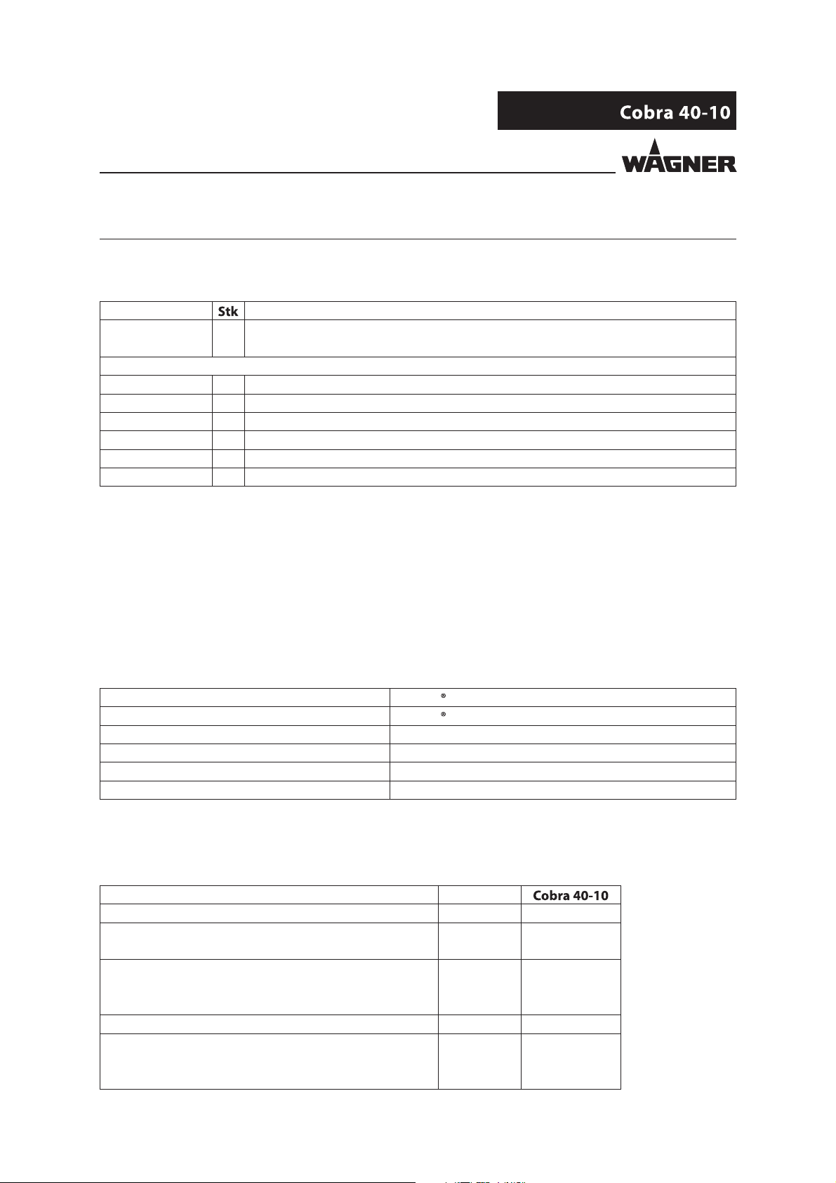
1.3 LANGUAGES
The operating manual is available in the following languages:
Language Order No. Language Order No.
German 2303152 English 2303675
French 2303676 Dutch 2303677
Italian 2303678 Spanish 2303679
Danish 2303680 Swedish 2303682
Portuguese 2343519
1.4 ABBREVIATIONS IN THE TEXT
Number of pieces
Position
Marking in the spare parts lists
Order No. Order number
Double stroke
Stainless steel
Two components
6
Page 7
VERSION 10/2013
ORDER NUMBER DOC 2303675
OPERATING MANUAL
2 CORRECT USE
2.1 DEVICE TYPES
Double diaphragm pump and spray pack:
2.2 TYPE OF USE
The device is suitable for processing liquid materials like paints and lacquers in accordance
with the classi cation into explosion classes IIA or IIB.
2.3 USE IN AN EXPLOSION HAZARD AREA
The double diaphragm pump can be employed in explosion hazard areas (Zone 1).
2.4 SAFETY PARAMETERS
WAGNER accepts no liability for any damage arising from incorrect use.
Use the device only to work with the products recommended by WAGNER.
Only operate the device as a whole.
Do not deactivate safety xtures.
Use only WAGNER original spare parts and accessories.
The double diaphragm pump may only be operated under the following conditions:
The operating sta must be trained on the basis of this operating manual.
The safety regulations listed in this operating manual must be observed.
The operating, maintenance, and repair information in this operating manual must
be observed.
The statutory requirements and accident prevention regulation standards in the country
of use must be observed.
7
Page 8
VERSION 10/2013
ORDER NUMBER DOC 2303675
OPERATING MANUAL
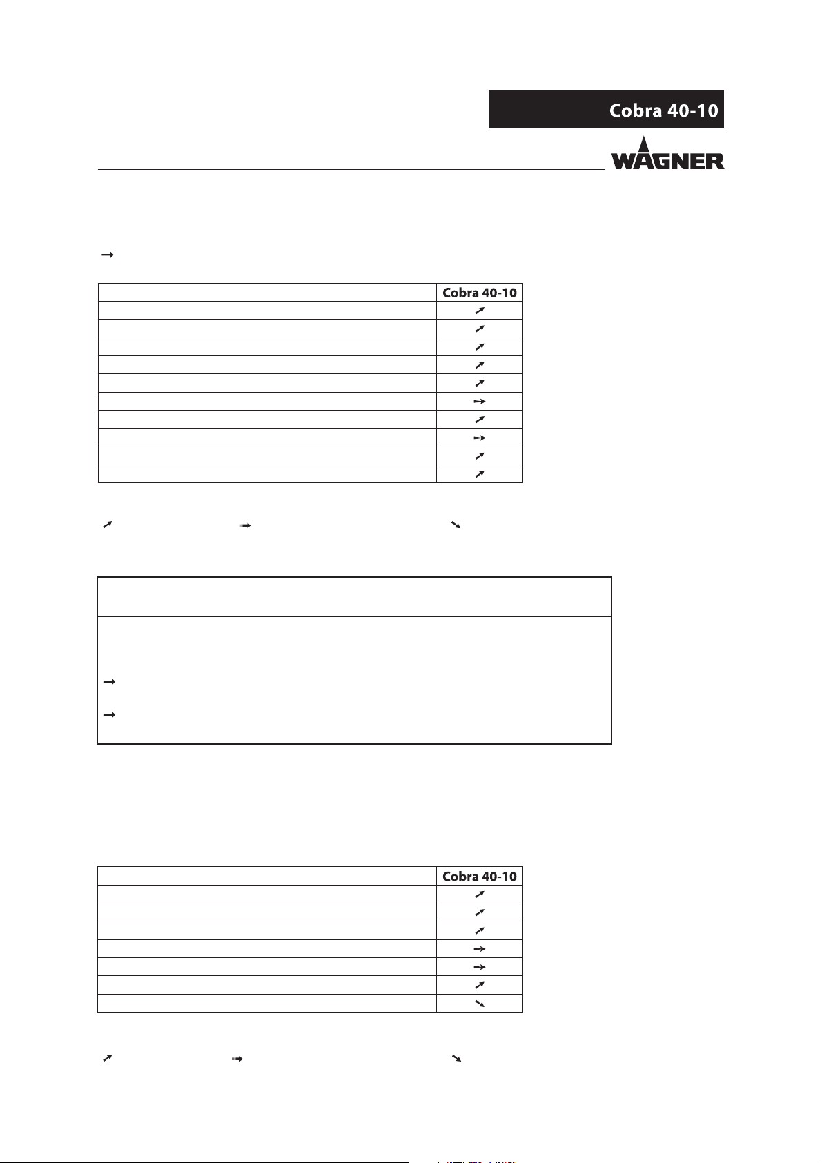
2.5 PROCESSIBLE WORKING MATERIALS
Fluid products such as paints and lacquers.
Application
Water-dilutable products
Solvent-based lacquers and paints
Two-component coating products
Emulsions
UV lacquers
Primers
Epoxy and polyurethane lacquers, phenolic lacquers
Liquid plastics
Wax-based underside protection
Shear-sensitive lacquers
Legend
recommended limited suitability less suitable
NOTICE
Abrasive working materials and pigments!
Greater wear of parts carrying the product.
Use the application-oriented model ( ow rate/cycle, product, valves, etc.) as
indicated in Chapter 5.2.2.
Check if the uids and solvents used are compatible with the pump construction
materials as indicated in Chapter 5.2.1.
2.5.1 RECOMMENDED APPLICATION AREAS
Application
Furniture industry
Kitchen manufacturers
Joinery
Window factories
Steel-processing industry
Construction of vehicles
Shipbuilding
Legend
recommended limited suitability less suitable
8
Page 9
VERSION 10/2013
ORDER NUMBER DOC 2303675
OPERATING MANUAL
2.6 REASONABLY FORESEEABLE MISUSE
The following is prohibited:
coating work pieces which are not grounded,
unauthorized conversions and modi cations to the double diaphragm pump,
processing dry or similar coating products, and
using defective components, spare parts, or accessories other than those described
in Chapter 10 of this operating manual.
The forms of misuse listed below may result in health issues and/or material damage:
use of powder as coating product and
incorrectly set values for processing.
Wagner double diaphragm pumps are not designed for pumping food.
2.7 RESIDUAL RISKS
Residual risks are risks which cannot be excluded even in the event of correct use.
If necessary, warning and prohibition signs at the relevant points of risk indicate residual
risks.
Residual risk Source Consequences Speci c measures Lifecycle phase
Skin contact with
lacquers and
cleaning agents
Paint in air outside
the de ned working
area
Handling of
lacquers and
cleaning agents
Painting outside the
de ned working
area
Skin irritations, Wear protective
clothing,
allergies observe safety data
sheets
Inhalation of
substances which
are hazardous to
health
Observe working
and operating
instructions
Operation,
maintenance,
disassembly
Operation,
maintenance
9
Page 10
VERSION 10/2013
ORDER NUMBER DOC 2303675
OPERATING MANUAL
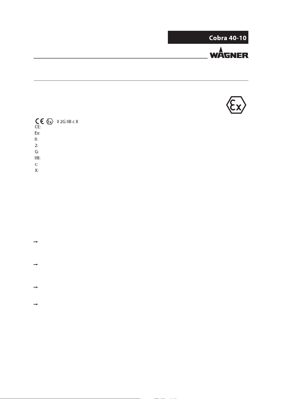
3 IDENTIFICATION
3.1 EXPLOSION PROTECTION IDENTIFICATION
As de ned in Directive 94/9/EC (ATEX 95), the device is suitable for use in potentially explosive
areas.
European Communities
Symbol for explosion protection
Device class II
Category 2 (Zone 1)
Ex-atmosphere gas
Explosion group
Constructional safety
Special Notes (see Chapter 3.2)
3.2 IDENTIFICATION X
X The maximum surface temperature corresponds to the permissible product
temperature. This and the permissible ambient temperature can be found in the
"Technical Data" chapter.
Maximum surface temperature
The maximum surface temperature of the pump depends on the operating conditions
(heated product) and not on the device (frictional heat).
Ignition temperature of the coating product
Ensure that the ignition temperature of the coating product is above the maximum
surface temperature.
Ambient temperature
The permissible ambient temperature is: +10 °C to +60 °C; +50 °C to 140 °F.
Medium supporting atomizing
To atomize the product, use only weakly oxidizing gases, e.g. air.
10
Page 11
VERSION 10/2013
ORDER NUMBER DOC 2303675
OPERATING MANUAL
4 GENERAL SAFETY INSTRUCTIONS
4.1 SAFETY INSTRUCTIONS FOR THE OPERATOR
Keep this operating manual to hand near the device at all times.
Always follow local regulations concerning occupational safety and accident prevention.
4.1.1 ELECTRICAL EQUIPMENT
Electrical devices and equipment
To be provided in accordance with the local safety requirements with regard to the
operating mode and ambient in uences.
May only be maintained by skilled electricians or under their supervision.
Must be operated in accordance with the safety regulations and electrotechnical
regulations.
Must be repaired immediately in the event of problems.
Must be decommissioned if they pose a hazard.
Must be de-energized before work is commenced on active parts. Inform sta about
planned work. Observe electrical safety regulations.
4.1.2 STAFF QUALIFICATIONS
Ensure that the device is operated and repaired only by trained persons.
4.1.3 SAFE WORK ENVIRONMENT
Ensure that the oor in the working area is static dissipative in accordance with
EN61340-4-1 (resistance must not exceed 100 MOhm).
Ensure that all persons within the working area wear static dissipative shoes.
Footwear must comply with EN 20344. The measured insulation resistance must not
exceed 100 Mohm.
Ensure that during spraying, persons wear static dissipative gloves. The grounding
takes place via the spray gun handle.
If protective clothing is worn, including gloves, it has to comply with EN 1149-5.
The measured insulation resistance must not exceed 100 Mohm.
Paint mist extraction systems must be tted on site according to local regulations.
Ensure that the following components of a safe working environment are available:
– Product/air hoses adapted to the working pressure.
– Personal safety equipment (breathing and skin protection).
Ensure that there are no ignition sources such as naked ames, sparks, glowing wires,
or hot surfaces in the vicinity. Do not smoke.
11
Page 12

VERSION 10/2013
ORDER NUMBER DOC 2303675
OPERATING MANUAL
4.2 SAFETY INSTRUCTIONS FOR STAFF
Always follow the information in these instructions, particularly the general safety instructions
and the warning instructions.
Always follow local regulations concerning occupational safety and accident prevention.
4.2.1 SAFE HANDLING OF WAGNER SPRAY DEVICES
The spray jet is under pressure and can cause dangerous injuries.
Avoid injection of paint or cleaning agents:
Never point the spray gun at people.
Never reach into the spray jet.
Before all work on the device, in the event of work interruptions and functional faults:
– Switch o the energy/compressed air supply.
– Relieve the pressure from the spray gun and device.
– Secure the spray gun against actuation.
– In the event of functional faults: remedy the fault as described in the "Troubleshooting"
chapter.
The liquid ejection devices are to be checked for safe working conditions by an expert
(e.g. Wagner Service Technician) as often as necessary or at least every 12 months,
in accordance with the guidelines for liquid emitters (ZH1/406 and BGR500 Part 2
Chapter2.36).
– For devices that have been shut down, the inspection can be postponed until the next
commissioning.
Carry out the work steps as described in the "Pressure Relief/Work Interruptions" chapter:
– if pressure relief is required.
– if the spraying work is interrupted or stopped.
– before the device is cleaned on the outside, checked, or serviced.
– before the spray nozzle is installed or cleaned.
In the event of skin injuries caused by paint or cleaning agents:
Note down the paint or cleaning agent that you have been using.
Consult a doctor immediately.
Avoid danger of injury through recoil forces:
Ensure that you have firm footing when operating the spray gun.
Only hold the spray gun brie y in a position.
12
Page 13
VERSION 10/2013
ORDER NUMBER DOC 2303675
OPERATING MANUAL
4.2.2 GROUNDING THE DEVICE
In order to avoid electrostatic charging of the device, the device must be grounded.
Friction, owing liquids, and air or electrostatic coating processes create charges. Flames or
sparks can form during discharge.
Ensure that the device is grounded for every spraying operation.
Ground the work pieces to be coated.
Ensure that all persons inside the working area are grounded, e.g. that they are wearing
static dissipative shoes.
Wear dissipative gloves when spraying. The grounding takes place via the spray gun handle.
4.2.3 PRODUCT HOSES
Ensure that the hose material is chemically resistant to the sprayed products.
Ensure that the product hose is suitable for the pressure generated in the device.
Ensure that the following information can be seen on the high-pressure hose:
– Manufacturer
– Permissible operating overpressure
– Date of manufacture
Make sure that the hoses are laid only in suitable places. In no case, should hoses be laid
in the following places:
– in high-traffic areas,
– on sharp edges,
– on moving parts, or
– on hot surfaces
Make sure that the hoses are never used to pull or move the device.
The electrical resistance of the complete high-pressure hose must be less than 1 Mohm.
Several liquids have a high expansion coe cient. In some cases their volume can rise with
consequent damage to pipes, ttings, etc. and cause uid leakage.
When the pump sucks liquid from a closed tank, ensure that air or suitable gas can enter
the tank to avoid a vacuum being generated in the tank itself. Thus a negative pressure is
avoided. The vacuum could implode the tank (squeeze) and can cause it to break. The tank
would leak and the liquid would ow out.
The pressure created by the pump is a multiplication of the inlet air pressure.
13
Page 14
VERSION 10/2013
ORDER NUMBER DOC 2303675
OPERATING MANUAL
4.2.4 CLEANING
De-energize the device electrically.
Disconnect the pneumatic supply line.
Relieve the pressure from the device.
Ensure that the flash point of the cleaning agent is at least 5 K above the ambient temperature.
To clean, use cloths and brushes moistened with solvent. Never use hard objects or spray
on cleaning agents with a gun.
Preferably, non-combustible cleaning agents should be used.
An explosive gas/air mixture forms in closed tanks.
When cleaning devices with solvents, never spray into a closed tank.
Only use electrically conductive tanks for cleaning liquids.
The tanks must be grounded.
4.2.5 HANDLING HAZARDOUS LIQUIDS, LACQUERS AND PAINTS
When preparing or working with lacquer and when cleaning the device, follow the
working instructions of the manufacturer of the lacquers, solvents and cleaning agents
being used.
Take the speci ed protective measures; in particular, make sure that you wear safety
goggles, protective clothing, and gloves, as well as skin protection cream if necessary.
Use a mask or a breathing apparatus if necessary.
For su cient health and environmental safety: operate the device in a spray booth or
on a spraying wall with the ventilation (extraction) switched on.
Wear suitable protective clothing when working with hot products.
4.2.6 TOUCHING HOT SURFACES
Only touch hot surfaces if you are wearing protective gloves.
When operating the device with a coating product with a temperature of > 43 °C; 109.4°F:
- Identify the device with a warning label "Warning - hot surface".
Order No.
9998910 Instruction label
9998911 Protection sticker
Note: Order the two stickers together.
14
Page 15
VERSION 10/2013
ORDER NUMBER DOC 2303675
OPERATING MANUAL
4.3 USE IN AREAS SUBJECT TO EXPLOSION HAZARDS
The pneumatic pump may be used in potentially explosive areas. The following safety
regulations must be observed and followed.
4.3.1 SAFETY REGULATIONS
Safe handling of WAGNER spray devices
Mechanical sparks can form if the device comes into contact with metal.
In an explosive atmosphere:
Do not knock or push the device against steel or rusty iron.
Do not drop the device.
Only use tools that are made of a permitted material.
Ignition temperature of the pumped product
Check that the ignition temperature of the pumped product is higher than the max.
allowable surface temperature.
Medium supporting atomizing
To atomize the product, use only weakly oxidizing gases, e.g. air.
Surface spraying, electrostatics
Do not spray device parts using electrostatic equipment.
Cleaning
If there are deposits on the surfaces, the device may form electrostatic charges. Flames or
sparks can form during discharge.
Remove deposits from the surfaces to maintain conductivity.
Only use a damp cloth to clean the device.
15
Page 16

VERSION 10/2013
ORDER NUMBER DOC 2303675
OPERATING MANUAL
4.3.2 OPERATION WITHOUT FLUID
Avoid running the pump so that it sucks in air (without uid inside). The air, combined with
the vapor of ammable uids, can generate internal areas with an explosion hazard.
Periodically check that the pump is working smoothly, paying special attention to the
presence of air in the pumped uid, which may be caused by damaged packings.
Avoid operating the pump with damaged packings.
Ensure that the separating agent tank is lled with su cient separating agent.
16
Page 17
VERSION 10/2013
ORDER NUMBER DOC 2303675
OPERATING MANUAL
5 DESCRIPTION
5.1 SCOPE OF DELIVERY
Order No. Designation
2301858 1 Frame-mounted diaphragm pump Cobra 40-10 consisting of:
Fluid section, air motor, connection elements
The standard equipment includes:
322981 1 Sign
236219 1 Grounding cable, complete
341434 1 Double open-end wrench
See Chapter 12.3 1 Conformity certi cate GM2000W
2303152 1 Operating manual, German
see Chapter 1 1 Operating manual in the local language
The delivery note shows the exact scope of delivery.
Accessories: see Chapter 10.
5.2 DATA
5.2.1 MATERIALS OF PAINTWETTED PARTS
Inlet housing Consital (aluminum alloy)
Fluid section Consital (aluminum alloy)
Valve balls Stainless steel
Valve seats/valve cone Carbide
Diaphragms Resistant PA
Valve tting 1.4104
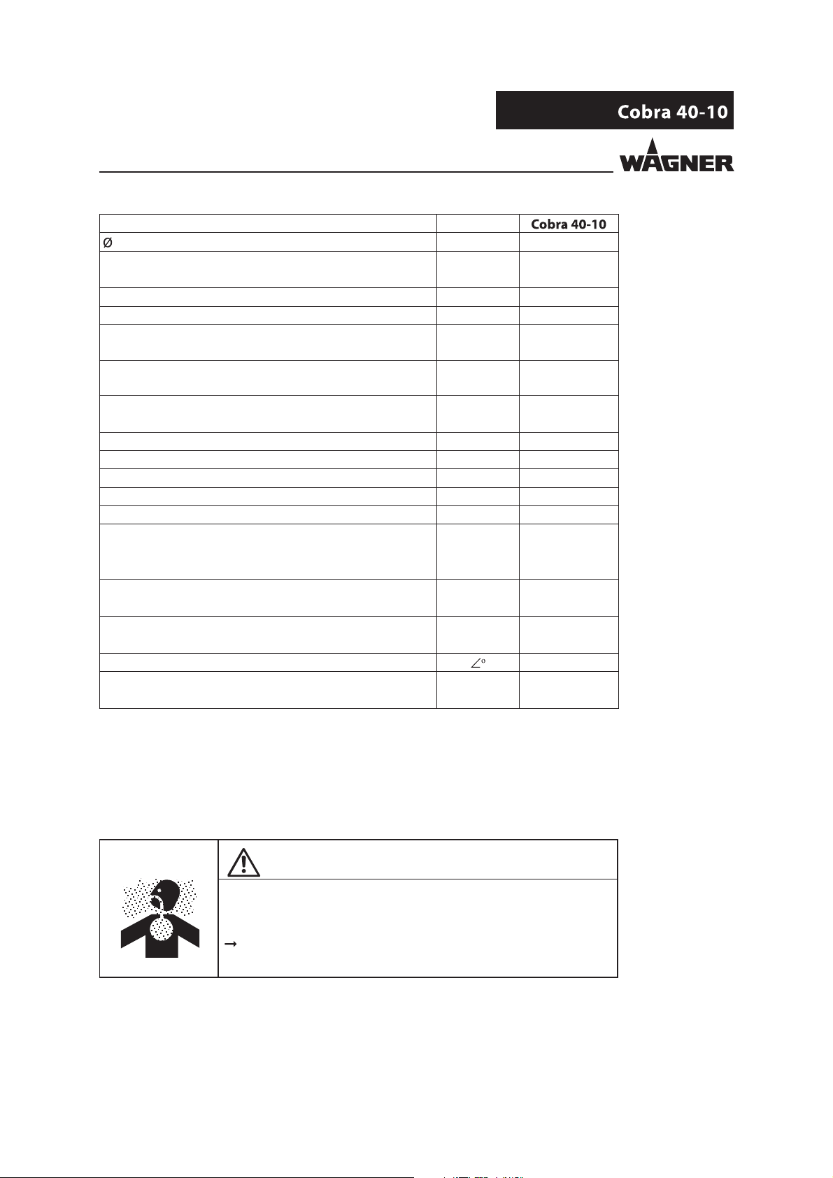
5.2.2 TECHNICAL DATA
Description Devices
Pump ratio 40:1
Volume ow per double stroke (DH) cm 10
cu inch 0.6
Maximum operating overpressure MPa 25
bar 250
psi 3626
Maximum possible strokes in operation DH/min 200
Minimum/maximum air inlet pressure MPa 0.25-0.6
bar 2.5-6
psi 36.3-87
17
Page 18
VERSION 10/2013
ORDER NUMBER DOC 2303675
OPERATING MANUAL
Description Devices
Air inlet (inside thread) inch G 1/2
Minimum Ø of the compressed air supply line mm 13
inch 0.51
Air consumption at 0.6 MPa; 6 bar; 87 psi per double stroke NL 3.5
Sound pressure level at maximum permissible air pressure* dB(A) 74
Sound pressure level at 0.45 MPa; 4.5 bar; 65.27 psi
air pressure*
Sound pressure level at 0.3 MPa; 3 bar; 43.5 psi
air pressure*
Air motor piston diameter mm 80
Product inlet (outside thread) mm M36x2
Product outlet connection (inside thread) inch G 3/8"
Product outlet (outside thread) inch G 1/4"
Weight kg; lb 19; 41.9
Product pH value pH 3.5-9
Maximum product pressure at pump inlet MPa 2
Product temperature °C +10 ÷ +80
Ambient temperature °C +10 ÷ +60
Allowable inclination for operation
Hydraulic oil lling amount (approximate) L 0.110
dB(A) 72
dB(A) 69
inch 3.15
bar 20
psi 290
°F +50 ÷ +176
°F +50 ÷ +140
±10
cu inch 6.71
* A-rated sound pressure level measured at 1 m distance, LpA1m, in accordance with
DINEN 14462: 2005.
Reference measurements have been made by SUVA (Swiss Accident Insurance Institute).
WARNING
Outgoing air containing oil!
Risk of poisoning if inhaled.
Provide compressed air free from oil and water (quality standard
5.5.4 according to ISO 8573.1) 5.5.4 = 40 m / +7 / 5 mg/m³.
18
Page 19
VERSION 10/2013
ORDER NUMBER DOC 2303675
OPERATING MANUAL
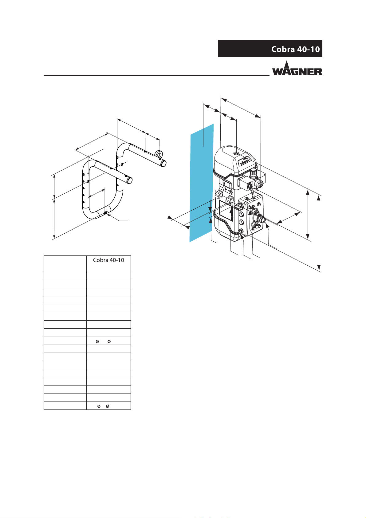
5.2.3 MEASUREMENTS AND CONNECTIONS
N
G
F
E
B
D
Cobra 40-10
P
O
Q
B_02943
Measurement
mm; inch
A 505; 19.88
B 313; 12.32
C 322; 12.68
D 134; 5.28
E 55; 2.16
F 182; 7.16
G 80; 3.15
HM6
I
25; 0.98
K G1/4"
L M36x2
M NPSM1/4-18
N 149; 5.87
O 91; 3.58
P 107; 4.21
Q 175; 6.89
R
7; 0.28
R
G
F
C
A
I
L
H
M
B_04235
K
19
Page 20
VERSION 10/2013
ORDER NUMBER DOC 2303675
OPERATING MANUAL
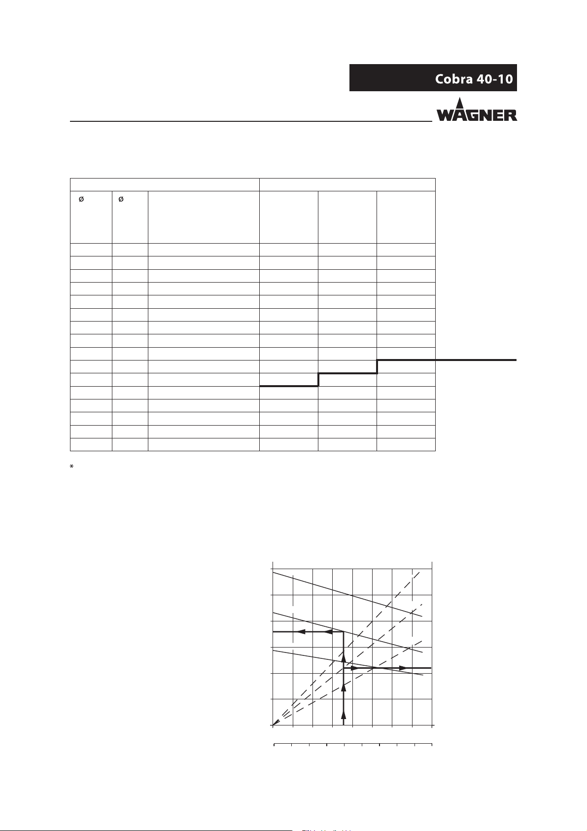
5.2.4 VOLUME FLOW
Wagner AL nozzles Volume ow in l/min.*
inch mm Spray angle at at at
7 MPa 10 MPa 15 MPa
70 bar 100 bar 150 bar
1015 psi 1450 psi 2175 psi
0.007 0.18 40° 0.1650 0.2000 0.2400
0.009 0.23 20-30-40-50-60° 0.2060 0.2500 0.3090
0.011 0.28 10-20-30-40-50-60° 0.2950 0.3450 0.4260
0.013 0.33 10-20-30-40-50-60-80° 0.4530 0.5280 0.6600
0.015 0.38 10-20-30-40-50-60-80° 0.5770 0.6720 0.8130
0.017 0.43 20-30-40-50-60-70° 0.7310 0.7860 1.0640
0.019 0.48 20-30-40-50-60-70-80° 0.9260 1.0920 1.3700
0.021 0.53 20-40-50-60-80° 1.1430 1.3600 1.6900
0.023 0.58 20-40-50-60-70-80° 1.3700 1.5900 2.0100 Cobra 40-10
0.025 0.64 20-40-50-60-80° 1.6200 1.9100 2.4000
0.027 0.69 20-40-50-60-80° 1.8300 2.1300 2.6800
0.029 0.75 60° 2.1900 2.5100 3.1700
0.031 0.79 20-40-50-60° 2.4000 2.7700 3.4900
0.035 0.90 20-40-50-60° 3.2200 3.7400 4.6900
0.043 1.10 20-50° 5.0700 6.0400 7.4600
0.052 1.30 50° 5.1200 6.5000 7.5200
Volume ow refers to water.
Maximum ranges for continuous operation at 200 DH/min.
5.2.5 PERFORMANCE DIAGRAMS
Stroke frequency (DH/min)
Example
BAR
BAR
BAR
Product pressure (bar)
"?
Water ow rate (nl/min)
BAR
BAR
BAR
Air consumption (nl/min)
20
Page 21

n
n
VERSION 10/2013
OPERATING MANUAL
Diagram for Cobra 40-10
ORDER NUMBER DOC 2303675
Stroke frequency (DH/min)
bar (MPa)
<psi>
250 (25)
<3625>
200 (20)
<2900>
150 (15)
<2175>
100 (10)
<1450>
Product pressure
50 (5)
<725>
B_01203
nl/min
NL/mi
40
0
80
120
160
200
<scfm>
240
1000
A
B
C
C
<35>
A
800
<28>
B
600
<21>
400
<14>
200
<7>
2.4
<0.6>
0
l/min
L/mi
<gpm>
Air consumption
0
0
0.4
<0.1>
0.8
<0.2>
1.2
<0.3>
1.6
<0.4>
2
<0.5>
Water ow rate
A = 6 bar (0.6 MPa; 87 psi) air pressure
B = 4.5 bar (0.45 MPa; 65 psi) air pressure
C = 3 bar (0.3 MPa; 44 psi) air pressure
21
Page 22

VERSION 10/2013
OPERATING MANUAL
5.3 FUNCTION
5.3.1 PUMP
Cobra 40-10
ORDER NUMBER DOC 2303675
13
1
4
6
7
8
2
5
3
9
10
14
B_04237
11
12
15
1 Control housing with integrated silencer
2 Air pressure regulator
3 Ball valve
4 Air motor
5 Compressed air inlet
6 Mounting ange
7 Relief valve
8 Product outlet
9 Fluid section
10 Product inlet
11 Grounding connection
12 Pressure stage casing
13 Return socket
14 Valve depressor
15 Exhaust air cap
General information
The double diaphragm pump is driven with compressed air. This compressed air moves the air piston in the air
motor (4), and consequently the piston rod in the pressure stage (9), up and down. At the end of each stroke
the compressed air is redirected by a reversing valve and the control piston. The up-and-down movement of
the 2 diaphragms within the uid section is produced by hydraulic oil, which is moved by the piston in the
pressure stage. With every stroke of the piston rod, working material is sucked in and delivered to the spray
gun at the same time.
Air motor (4)
The air motor with its pneumatic reverse (1) does not require pneumatic oil.
The compressed air is fed to the motor via the air pressure regulator (2) and the ball valve (3).
The air motor is tted with a safety valve. The safety valve has been set and sealed at the factory. In case
of pressures over and above the permissible operating pressure, the valve, which is held with a spring,
automatically opens and releases the excess pressure.
22
Page 23

VERSION 10/2013
ORDER NUMBER DOC 2303675
OPERATING MANUAL
WARNING
Overpressure!
Risk of injury from bursting components.
Never change the safety valve setting.
Fluid section (9)
The uid section has been designed as a double diaphragm pump with exchangeable
inlet and outlet valves. Change between "spraying mode" and "circulation mode" using
the relief valve (7).
Positioning
The Cobra pump may only be operated in a horizontal
or vertical position as shown in the diagrams. Overhead
operation is not permitted.
"?
B_01205
Vertical positioning Horizontal positioning
NOTICE
Overhead operation or storage (air motor with pressure regulator below)
Air could get into the hydraulic circuit, causing a malfunction.
Avoid overhead operation or storage at all costs.
Vent, see service manual.
B_01207
Overhead positioning
23
Page 24

VERSION 10/2013
ORDER NUMBER DOC 2303675
OPERATING MANUAL
5.3.2 PRESSURE REGULATOR UNIT FOR COBRA
1 Pressure regulator
2 Ball valve
3 Pressure gauge
4 Compressed air inlet
5 AirCoat lter regulator Cobra (accessories)
1
The AirCoat lter regulator must be mounted vertically
in all installation positions for the diaphragm pump
(see assembly manual for Filter Regulator, order
number2328614).
Positions of the ball valve
1 Open: working position
2 Closed: The air motor can still be under pressure.
3 Ven t: Operating pressure in the air motor is vented
(control pressure is still present).
5
2
3
4
B_04300
3
2
1
B_04301
24
Page 25

VERSION 10/2013
ORDER NUMBER DOC 2303675
OPERATING MANUAL
6 ASSEMBLY AND COMMISSIONING
6.1 INSTALLATION AND CONNECTION
6.1.1 INSTALLING THE PUMP
Note:
This pump can be used as part of a spraying system for Airless or AirCoat applications.
The components can be found in the accessories list, provided that the system was not
obtained as a spray pack.
The nozzles must be selected according to the gun instructions.
Procedure:
1 Mount the pump on a base frame, trolley
(6), or wall mount.
2 For AirCoat systems: Mount the additional
lter pressure regulator (7) (optional).
3 Mount suction system (5).
4 Mount return hose (4) (optional).
5 Connect high-pressure hose and spray gun
(2) as described in the operating manual.
2
6
7
1
4
5
B_04239
WARNING
Inclined ground!
Risk of accidents if the device rolls away/falls.
Position the trolley with the piston pump horizontally.
If the surface is inclined, position the feet of the trolley towards
the gradient.
Secure the trolley.
25
Page 26

VERSION 10/2013
OPERATING MANUAL
6.1.2 GROUNDING
Discharge of electrostatically charged components in atmospheres
containing solvents!
Explosion hazard from electrostatic sparks.
Only use a damp cloth to clean the piston pump.
Heavy paint mist if grounding is insu cient!
Danger of poisoning.
Insu cient paint application quality.
ORDER NUMBER DOC 2303675
WARNING
WARNING
Ground all device components.
Ground the work pieces to be coated.
Grounding scheme (example)
Pump
Paint tank
Conveyor
Work piece
2MAX-7
"?
Spraying stand
Floor static dissipative
26
Page 27

VERSION 10/2013
ORDER NUMBER DOC 2303675
OPERATING MANUAL
Cable cross sections
Pump 4 mm; AWG11
Paint tank 6 mm; AWG10
Conveyor 16 mm; AWG5
Booth 16 mm; AWG5
Spraying stand 16 mm; AWG5
Procedure:
1 Screw on grounding cable with eye.
2 Clamp the grounding cable clip to a grounding
connection on site.
3 Ground the product (paint) tank to an on-site
grounding connection.
4 Ground the other parts of the system to an on-site
grounding connection.
"?
27
Page 28

VERSION 10/2013
ORDER NUMBER DOC 2303675
OPERATING MANUAL
6.2 COMMISSIONING
6.2.1 SAFETY INSTRUCTIONS
Every time before starting up, the following points should be observed as laid down in the
operating manual:
- Observe all safety regulations in accordance with Chapter 4.
- Carry out commissioning properly.
WARNING
High-pressure spray jet!
Danger to life from injecting paint or solvent.
Never reach into the spray jet.
Never point the spray gun at people.
Consult a doctor immediately in the event of skin injuries caused
by paint or solvent. Inform the doctor about the paint or solvent
used.
Never seal defective high-pressure parts; instead relieve the
pressure from them and replace them.
WARNING
Toxic and/or ammable vapor mixtures!
Risk of poisoning and burns.
Operate the device in a spray booth approved for the working
materials.
-or Operate the device on an appropriate spraying wall with the
ventilation (extraction) switched on.
Observe national and local regulations for the outgoing air speed.
WARNING
Gas mixtures can explode if there is an incompletely filled pump!
Danger to life from ying parts.
Ensure that the pump and suction system are always completely
filled with cleaning agent or working medium.
Do not spray the device empty after cleaning.
28
Page 29

VERSION 10/2013
ORDER NUMBER DOC 2303675
OPERATING MANUAL
Before every start-up, the following points should be observed:
- Secure gun with safety clip.
- Check the permissible pressures.
- Check all connecting parts for leaks.
- Check hoses for damage.
It should be ensured that the device is in the following state before carrying out any work
on it:
- The pressure should be released from the pump and high-pressure hose with gun.
- The gun should be secured with the safety clip.
- The air supply should be interrupted.
29
Page 30

VERSION 10/2013
ORDER NUMBER DOC 2303675
OPERATING MANUAL
Cobra EMERGENCY STOP
In the event of unforeseen occurrences, the ball valve (1) should be vented immediately
and the relief valve (2) opened.
1
2
➀
B_04099
vent
Open
B_04302
➁
Switch position
Circulation
B_04303
30
Page 31

VERSION 10/2013
ORDER NUMBER DOC 2303675
OPERATING MANUAL
6.2.2 BASIC FLUSHING
1 Place empty tank (5) under return tube (4).
2 Place suction hose (7) in a tank with cleaning
agent (6).
3 Adjust the pressure regulator (1) to approx. 0.05MPa;
0.5 bar; 7.25 psi.
4 Open relief valve (3).
5 Slowly open the ball valve (2).
6 Adjust the air pressure on the pressure regulator
(1) so that the pump runs smoothly.
7 Rinse the system until the cleaning agent that ows
into the tank (5) is clean.
8 Close ball valve (2).
9 Reverse the relief valve (3).
10 Point the gun, without nozzle, into tank (5)
and open it.
11 Slowly open the ball valve (2).
12 Flush until clean ushing agent ows from the gun.
13 Close ball valve (2).
14 When there is no pressure remaining in the system, close the gun.
15 Secure the gun.
16 Dispose of the contents of the tank (5) according to the local regulations.
B_04240
1
2
3
7
9
4
5
6
V
Note:
During the ushing procedure, brie y press both valve depressors (V).
"?
31
Page 32

VERSION 10/2013
ORDER NUMBER DOC 2303675
OPERATING MANUAL
6.2.3 FILLING WITH WORKING MATERIAL
Positions of the ball valve
1 Open: working position
2 Closed: The air motor can still be under pressure.
3 Ven t: Operating pressure in the air motor is vented
(control pressure is still present).
1 Place suction hose (7) and return tube (4) into the
tank with the working material (6).
2 Adjust the pressure regulator (1) to approx. 0.05 MPa;
0.5 bar; 7.25 psi.
3 Open relief valve (3).
4 Slowly open the ball valve (2).
5 Adjust the air pressure on the pressure regulator (1)
so that the pump runs smoothly.
6 Close ball valve (2) as soon as pure working material
starts coming from the return tube (4).
7 Set relief valve (3) to "spray".
8 Point the gun, without nozzle, into tank (5) and
open it.
9 Slowly open the ball valve (2).
10 Close ball valve (2) as soon as pure working
material starts coming from the gun.
11 When there is no pressure remaining in the system,
close the gun.
12 Secure the gun.
3
2
1
B_04301
Circulation
mode
Relief valve
B_04303
Spraying mode
32
Page 33

VERSION 10/2013
ORDER NUMBER DOC 2303675
OPERATING MANUAL
7 OPERATION
7.1 SPRAYING
Positions of the ball valve
1 Open: working position
2 Closed: The air motor can still be under pressure.
3 Ven t: Operating pressure in the air motor is vented
(control pressure is still present).
3
2
1
1 Secure gun and place nozzle in the gun.
2 Slowly open the ball valve.
3 Set the required working pressure on the pressure
regulator.
4 Optimize the spraying results as laid down in the gun instructions.
5 Start work process.
Note: Depending on the function, the pump may continue running for 1 - 6 DH/min. after the spray gun is closed.
B_04301
7.2 WORK INTERRUPTION
1 Close gun.
2 Close ball valve.
3 Release the system by opening the gun.
4 Close and secure gun.
If the system has been used with 2K products:
NOTICE
Hardened working material in the spraying system when 2K product is processed!
Destruction of pump and injection system.
Follow the manufacturer‘s processing rules, particularly regarding the pot life.
Flush thoroughly before the end of the pot life.
33
Page 34

VERSION 10/2013
ORDER NUMBER DOC 2303675
OPERATING MANUAL
7.3 DECOMMISSIONING AND CLEANING
Note:
The device should be cleaned for maintenance purposes, etc. Ensure that no remaining
product dries on and sticks to the device.
Procedure:
1 Carry out work interruption -> refer to Chapter 7.2.
2 Carry out basic ushing -> refer to Chapter 6.2.2.
3 Maintain the gun according to the operating manual.
4 Clean and check the suction system and the suction lter.
6 Clean the outside of the system.
7 Put the whole system back together.
8 Fill the system with cleaning agent as described in Chapter 6.2.3 "Filling with working
material".
WARNING
Brittle lter pressure regulator!
The tank on the lter pressure regulator becomes brittle through contact
with solvents and can burst.
Flying parts can cause injury.
Do not clean the tank on the lter pressure regulator with solvent.
WARNING
Gas mixtures can explode if there is an incompletely filled pump!
Danger to life from ying parts.
Ensure that the pump and suction system are always completely
filled with cleaning agent or working medium.
Do not spray the device empty after cleaning.
7.4 LONGTERM STORAGE
If storing the system for a prolonged period of time, thorough cleaning and corrosion
protection are necessary. Replace the water or solvent in the material pump with a suitable
preserving oil and ll the separating agent cup with separating agent.
Procedure:
1 Carry out points 1 through 7 in Chapter 7.3 "Decommissioning and Cleaning".
2 Flush with preservative according Chapter 6.2.2.
34
Page 35

VERSION 10/2013
ORDER NUMBER DOC 2303675
OPERATING MANUAL
8 TROUBLESHOOTING, MAINTENANCE, AND REPAIR
8.1 TROUBLESHOOTING AND RECTIFICATION
Problem Cause Remedy
Pump does not work. Air motor does not work or stops. Open and close ball valve on the
pressure regulator unit or brie y
disconnect compressed air supply.
No pressure indication on the pressure
gage (air pressure regulator defective).
Spray nozzle is clogged. Clean the nozzle according to the
Insu cient compressed air supply. Check compressed air supply.
Filter insert in spray gun or high-
pressure lter is clogged.
Fluid section or high-pressure hose is
blocked (e.g. 2K product hardened).
Grease in spool and sleeve assembly. Degrease spool and sleeve assembly.
Pump stops at the stroke end
occasionally.
Poor spray pattern. See gun instructions.
Irregular operation of product
pump: spray jet collapses
(pulsation)
Strongly irregular operation
of material pump.
The pump runs evenly, does
not however, suck up product.
Viscosity is too high. Thin spraying product.
Spraying pressure is too low. Increase air inlet pressure.
Valves are clogged. Press valve depressor.
Foreign body in suction valve. Dismount suction valve housing, clean,
Diameter of compressed air line too
small.
Valves, packings, or pistons are worn
out.
Control air lter or work air lter is
clogged.
Diaphragms "blocked" because
suction is too fast.
The suction system's union nut is
loose; the pump is taking in air.
Suction lter is clogged. Clean lter.
Valves are clogged. Press valve depressor.
Disconnect compressed air supply
brie y or repair or change pressure
regulator.
instructions.
Clean the parts and use a suitable
working material.
Dismount and clean uid section,
replace high-pressure hose.
Check detent body.
Use a smaller nozzle.
Clean product pump and leave to soak
in cleaning agent if necessary.
and check valve seat.
Assemble a larger supply line
-> Technical data, see Chapter 5.2.2.
Replace the parts.
Check lter and clean it if necessary.
Operate pump with ball valve opened
a minimal amount for a while.
Tighten.
Clean product pump and leave to soak
in cleaning agent if necessary.
35
Page 36

VERSION 10/2013
ORDER NUMBER DOC 2303675
OPERATING MANUAL
Problem Cause Remedy
Pump runs fast when the
spray gun is closed.
Loss of power due to severe
icing.
If none of the causes of malfunction mentioned are present, the defect can be remedied by a WAGNER Service Center.
Valves worn. Replace the parts.
There is a lot of condensation water
in the air supply.
Install a water separator.
36
Page 37

VERSION 10/2013
OPERATING MANUAL
9 MAINTENANCE
Incorrect maintenance/repair!
Danger to life and damage to the device.
Only a WAGNER service center or a suitably trained person may
carry out repairs and replace parts.
Only repair and replace parts that are listed in the "Spare Parts
Catalogue" chapter and that are assigned to the device.
Before all work on the device and in the event of work interruptions:
- Disconnect the control unit from the mains.
- Relieve the pressure from the spray gun and device.
- Secure the spray gun against actuation.
Observe the operating manual and service instructions at all
times when carrying out work.
ORDER NUMBER DOC 2303675
WARNING
1 Check and clean the high-pressure lter every day or as required.
2 Each decommissioning procedure should be carried out as described in Chapter 7.3.
3 Check hoses, pipes, and couplings every day and replace if necessary.
WAGNER recommends having all spraying devices checked annually by a technical
expert (e.g. WAGNER service technician) for safety reasons.
37
Page 38

VERSION 10/2013
ORDER NUMBER DOC 2303675
OPERATING MANUAL
9.3 HYDRAULIC STAGE MAINTENANCE
Dismount the device onto a stand as shown in the picture and turn it upside down.
Observe the ll level marking (X) on the oil tank.
1
B_04241
B_04242
9.3.1 CHECKING THE OIL LEVEL
1 Start up the pump for a short time without any product.
2 Then read oil level A.
Dismount the device onto a stand as shown in the picture and
turn it upside down.
Observe the ll level marking (X) on the oil tank.
Oil level A in the oil tank (1) has to be within the speci ed markings (X).
If the level deviates from these markings, the hydraulic oil must be
topped up.
Procedure:
1 Unscrew and remove threaded plug (5).
2 Top up oil to level A = middle of marking X.
3 Start up the pump for a short time without any product and check for air bubbles.
4 Screw in threaded plug (5) and tighten with 2 Nm; 1.5 lbft.
max.
X
min.
A5
B_04243
NOTICE
Using hydraulic oil
Using the wrong hydraulic oil can cause a malfunction.
Use only original hydraulic oil - Wagner Order No. 322912 (250 ml or 15 cu inch).
38
Page 39

VERSION 10/2013
ORDER NUMBER DOC 2303675
OPERATING MANUAL
9.3.2 CHANGING THE OIL
The oil should be changed after 500 service hours or once a year.
Necessary accessories:
Order No. 322911 Oil lling set
NOTICE
Using hydraulic oil
Using the wrong hydraulic oil can cause a malfunction.
Use only original hydraulic oil - Wagner Order No. 322912 (250 ml or 15 cu inch).
Discharging oil
Procedure:
1 Decommission and clean the device -> follow Chapter 7.3 up to and including point 6.
2 Position device as shown in the picture and dismount the hood and casing.
3 Unscrew piston cover (1).
4 Place empty oil collector (2) under the oil tank.
5 Unscrew oil tank (3) and drain contents.
6 Unscrew and remove locking screws (4) and seals.
7 Slowly start up the pump until no oil ows out of the oil suction tting.
8 Screw in clean oil tank (3) and seal.
4
B_04241
B_04244
1
2
3
39
Page 40

VERSION 10/2013
ORDER NUMBER DOC 2303675
OPERATING MANUAL
CAUTION
Environmental pollution caused by waste oil!
Waste oil in the sewage network or spilled on the ground causes
severe environmental damage.
Groundwater pollution is liable to prosecution.
Collect waste oil and bring it to a collection point.
Waste oil is taken back by the seller when purchasing hydraulic oil.
Filling hydraulic stage with oil
Procedure:
1 Turn pump (mounted on the base frame) upside down.
2 Unscrew and remove threaded plug (5).
3 Unscrew 2 locking screws (4) and replace with 2 screw ttings (6) from the oil lling set.
4 Connect hoses with Y-pieces (7).
5 Fill syringe (8) with hydraulic oil and insert into hose.
6 Move piston (9) into front end position. Use the syringe to ll the hydraulic stage until
the oil ows out of the suction tting into the oil tank (3) with no air bubbles.
7 Move piston (9) into rear end position. Use the syringe to ll the hydraulic stage until
the oil ows out of the suction tting into the oil tank (3) with no air bubbles.
8 Continue to top up the oil until the level before venting is approx. 17 mm; 0.67 inches
below the upper edge of the oil tank.
9 Screw in threaded plug (5) and tighten gently. Put pump on its side and dismount oil
lling set. Seal the ller openings tightly with 2 locking screws (4).
B_04245
5
9
17 mm; 0.67in
7
4
8
6
B_04246
40
Page 41

VERSION 10/2013
ORDER NUMBER DOC 2303675
OPERATING MANUAL
Vent
Procedure:
1 Turn the pump upside down. Remove the threaded plug (5).
2 Slowly start up (vent) the pump until no air bubbles appear from the oil suction tting.
3 Oil level A in the oil tank has to be within the speci ed markings (X).
4 Screw in threaded plug (5) and tighten with 2 Nm; 1.5 lbft.
5 Mount piston cover (1) and hood with casing.
6 The device is ready for operation again.
A5
5
X
9
1
B_04243
B_04247
41
Page 42

VERSION 10/2013
ORDER NUMBER DOC 2303675
OPERATING MANUAL
10 ACCESSORIES
10.1 COBRA 4010 ACCESSORIES
Accessories list for Cobra 40-10
Order No. Designation
A 2301858 Diaphragm pump Cobra 40-10
1 322912 Hydraulic oil (for pressure stage) 250 ml; 250 cc
2 236219 Grounding cable 3 m; 9.8 ft
3 2333479 AirCoat lter pressure regulator
4 341434 Double open-end wrench
7 2325343 Fitting DF-MM-R1/4"-M12-PN270-SSt
11 2323325 Air suction lter DN25
12 2329046 Return hose DN6-PN310-G1/4"-PA
13 2324116 Suction hose DN25
14 2333163 Return tube for item 15
15 2344505 Hopper set 5L Cobra
16 2321424 Small quantity cup
17 2324110 Suction hose DN16
20 322052 Frame, complete
21 2332143 Wall mount 4", complete
24 2323396 Air suction lter DN16
25 2325901 Trolley 4", complete
51 322911 Oil lling set with 100 ml; 100 cc syringe
52 322916 Air coupling set DN 10 mm; 0.39 inch
53 9985619 Hose connector with sealing ring
= Wearing parts
Regarding position 7:
Fitting (7) can be screwed in instead of the relief valve. In this case, the required ball valve
must be provided by the customer. The return hose can no longer be connected to the
"return socket" output.
42
Page 43

VERSION 10/2013
OPERATING MANUAL
ORDER NUMBER DOC 2303675
Cobra 40-10
53
52
7
16
4
3
1
AirCoat
A
2
51
12
14
12
13
15
17
B_04285
B_04234
20
21
11
24
25
43
Page 44

VERSION 10/2013
ORDER NUMBER DOC 2303675
OPERATING MANUAL
11 SPARE PARTS
11.1 HOW CAN SPARE PARTS BE ORDERED?
Always supply the following information to ensure delivery of the right spare part:
Order number, designation, and quantity
The quantity need not be the same as the number given in the " " column in the
lists. This number merely indicates how many of the respective parts are used in each
component.
The following information is also required to ensure smooth processing of your order:
- Billing address
- Delivery address
- Name of the person to be contacted in the event of any queries
- Type of delivery (normal mail, express delivery, air freight, courier, etc.)
Identi cation in spare parts lists
Explanation of column "
Wearing parts
Note: No liability is assumed for wearing parts.
Not part of the standard equipment but available as a special accessory.
" (labeling) in the following spare parts lists:
WARNING
Incorrect maintenance/repair!
Risk of injury and damage to the device.
Have repairs and part replacements carried out only by specially
trained sta or a WAGNER service center.
Before all work on the device and in the event of work interruptions:
- Switch o the energy/compressed air supply.
- Relieve the pressure from the spray gun and device.
- Secure the spray gun against actuation.
Observe the operating manual and service instructions at all
times when carrying out work.
44
Page 45

VERSION 10/2013
ORDER NUMBER DOC 2303675
OPERATING MANUAL
11.2 OVERVIEW OF THE COBRA 4010 COMPONENTS
Order No. Designation
1 1 - Air motor 3/53
2 1 - Preassembled Cobra 40-10 uid section
3 1 322436 Air motor casing
4 1 322437 Pressure stage casing
5 1 322235 Hood 4 with air outlet
6 3 9907224 Hexagon socket head cap screw
7 4 9920106 Washer
8 1 9900107 Hexagon screw
9 1 2332077 Warning label
10 4 9999211 Edge protection pro le 30 mm; 1.18 inch
11 2 9999211 Edge protection pro le 164 mm; 6.46 inch
12 1 2332082 Fluid warning label
13 1 322438 Cylinder noise insulation
14
15 1 367913 Fitting-DF-MM-G3/8"-M16x1.5-PN530-SSt
16 1 9992616 Molykote DX grease
17 1 9992699 Loctite 406
= Wearing parts
1 9974112 Sealing ring
13
3
2
25 Nm; 18 lbft
16
1
9
10
30 Nm; 22 lbft
17
11
14
15
12
4
B_04250
7
6
5
7
8
45
Page 46

VERSION 10/2013
ORDER NUMBER DOC 2303675
OPERATING MANUAL
11.3 COBRA 4010 AIR MOTOR
Order No. Designation
1 1 9998718 Drive fastener
2 1 367318 Shoulder screw 4
3 1 9925033 Washer
4 1 367311 Hood 4
5 1 367319 Sound absorbing mat 4
6 1 9999152 Velcro fastener coating part
7 1 9999151 Velcro fastener adhesive part
8 1 367318 Shoulder screw 4
9 1 9925033 Washer
10 1 367310 Silencer 4
11
12 1 9974097 O-ring
13 3 9900325 Socket cap screw
14 3 9920103 Washer A6.4
15 1 367309 Connecting part 4
16 2 367320 Cotter pin
17
18 2 9998674 Threaded plug
19 1 9998274 Threaded plug
20 1 367315 Control housing 4
21
22 1 2328606 Pressure regulator unit 4
25 1 9999228 Threaded connector L
26 2 367307 Sealing plug 4/6
27
28 1 367324 Filter holder
29
30
31 2 9974095 O-ring
32 1 368285 Safety valve 0.63 MPa; 6.3 bar; 91 psi
33 1 9943080 Spool and sleeve assembly, complete
34 1 368038 Detent body, complete, ISO 1/2
35 2 9907126 Screw SFS Plastite 45
36 2 9974089 O-ring
37 2 9974115 O-ring
38 1 322432 Control air pipe
39 1 322430 Cylinder pipe
40 1 322431 Compressed air pipe
41
42 1 2310635 Edge ball valve mini 4
= Wearing parts
= Included in service set
= Not part of the standard equipment but available as a special accessory.
1 9974098 O-ring
1 369290 Pilot valve
1 367313 Compressed air lter 4/6
2 9974085 O-ring
1 367314 Control air lter
1 322910 Cobra outlet seal set (consisting of 2 seals)
2 9971448 O-ring
46
Page 47

VERSION 10/2013
OPERATING MANUAL
ORDER NUMBER DOC 2303675
22
Cobra 40-10
*
59
D
54
52
60
58
17
19
20
1
2
3
4
5
8
9
10
11*
12*
13
14
15
16
21
55
18
26
27*
28
29
30
10-15 Nm; 7-11 lbft
7
6
20-25 Nm; 15-18 lbft
2-3 Nm; 1.5-2.2 lbft
Do not dismount the piston
31*
32
46*
57
56
35
36*
37*
38
53
56
60
58
26
27
34
33
25
44
42
43*
46*
D
47
48
50*
44
49
59
51
45
50*
39
40
41*
59
B_04251
47
Page 48

VERSION 10/2013
ORDER NUMBER DOC 2303675
OPERATING MANUAL
Order No. Designation
43 1 9971137 O-ring
44 4 9900316 Hexagon socket head cap screw M6x50
45 2 9907039 Hexagon socket head cap screw M6x80
46
47 1 2341175 Manometer with air regulator 0-10 bar, G1/8"
48 1 2309972 Pressure regulator
49 1 - Distributor piece mini 4
50 2 9974166 O-ring
51 1 9904407 Locking screw R1/4
52 1 9974217 Rod seal
53 1 9992816 Adhesive
54
55 1 9990861 Ribbed plug
56 2 368313 Damper ISO1 and ISO2
57 6 9971123 O-ring
58 1 9992590 Loctite 222 50 ml; 50 cc
59 1 9992831 Loctite 542 50 ml; 50 cc
60 1 9992616 Molykote DX grease
= Wearing parts
= Included in service set
= Not part of the standard equipment but available as a special accessory.
1 9971313 O-ring
1 322439 Air motor noise insulation
2341627 Cobra 40-10 air motor service set
48
Page 49

VERSION 10/2013
OPERATING MANUAL
ORDER NUMBER DOC 2303675
49
Page 50

VERSION 10/2013
ORDER NUMBER DOC 2303675
OPERATING MANUAL
11.4 COBRA 4010 FLUID SECTION
51
109
Notes:
The piston rod (25) may only be mounted
with the screwed-on assembly pin (108).
53
59
57
111
29
59
61
62
70
30
31
32
34
33
35
7
60
63
111
108
7
53
54
55
B_04252
Grease all o-rings and seals lightly with
grease (111) before mounting them.
Cobra 40-10 uid section
Order No. Designation
1 1 2329898 Sealing sleeve
2 4 9900204 Hexagon screw
3 4 9920102 Washer
4 2 341241 Inlet valve depressor, complete, see Chapter 11.10
5 1 2330764 Inlet housing
= Wearing parts
= Included in the service set for Cobra 40-10 uid section
= Not part of the standard equipment but available as a special accessory.
50
Page 51

VERSION 10/2013
OPERATING MANUAL
Cobra 40-10
89
90
110
105
ORDER NUMBER DOC 2303675
4
1
2
3
5
70 Nm; 52 lbft
6
7
110
50 Nm; 37 lbft
23
102
66
67
42
2 Nm; 1.5 lbft
26
27
40
38
93
17
112
20 Nm;
15 lbft
94
95
35
96
33
97
13
98
25
34
90 Nm;
66 lbft
99
22
32
31
19
100
18
21
40 Nm; 29.5 lbft
46
110
47
110
92
24
101
102
30 Nm; 22 lbft
67
26
27
8
9
110
50
10
110
16
20
15
91
69
14
110
110
78
11
78
103
49
20 Nm;14.8 lbft
41
B_04253
51
Page 52

VERSION 10/2013
ORDER NUMBER DOC 2303675
OPERATING MANUAL
Cobra 40-10 uid section
Order No. Designation
6 8 9907234 Hexagon screw
7 10 9920107 Washer
8
9 2 322411 Valve tting
10 2 341336 Clasp
11
13 1 2330810 Connection piece
14 1 322410 Fluid section
15 2 322412 Plug
16 2 9904311 Screw plug
17
18 1 322915 Outlet valve set, complete (spare parts for 2 valves)
19 1 2330776 Fitting DF-MM-G3/8-3/8NPSM-530bar-SSt
20 1 322913 Complete diaphragm set with insert (comprising 2 diaphragms)
21 2 9904306 Screw plug
22
23 1 322401 Pressure stage D19/53
24 3 9907041 Hexagon screw
25 1 322402 Piston rod D19/53
26 2 9941502 Ball
27
29 1 9962028 Permaglide bushing
30 1 322403 Pressure stage ange
31
32 2 9974183 Rod sealing set
33
34 2 9971446 O-ring
35 2 322405 Pressure disk
36 1 2339250 Oil suction tting
37 1 115944 O-ring
38 1 2333498 Oil tank, complete
40 1 9998274 Threaded plug M7x1
41 1 322435 Piston cover
42 1 2334842 Pressure relief valve
46 1 322404 Pressure stage cover disk
47
49 4 9907233 Hexagon screw
50 4 9920102 Washer
51 1 9910101 Hexagon nut
53
= Wearing parts
= Included in the service set for Cobra 40-10 uid section
= Not part of the standard equipment but available as a special accessory.
2 9974184 O-ring
1 322914 Inlet valve set, complete (comprising 2 valves), see Chapter 11.9
1 169248 Relief valve, complete, see Chapter 11.11
2 9970127 Sealing ring
2 9971189 O-ring
2 9974182 Rod sealing pro le BS
2 9974186 O-ring
1 9974074 O-ring
2 322427 Damping washer
52
Page 53

VERSION 10/2013
ORDER NUMBER DOC 2303675
OPERATING MANUAL
Cobra 40-10 uid section
Order No. Designation
54 1 9974181 Piston sealing pro le Z5
55 1 322426 Piston air motor 3
57
59 2 9974185 Seal wiper ring, pro le EM
60 1 322425 Air motor ange
61 1 367258 Grounding, complete
62
63 1 9998675 Threaded plug
66 1 9998780 Pressure spring
67 2 322407 Oil valve screw
68 3 9971162 O-ring
69 2 322415 Insert
70 1 9974217 Rod seal
78 4 341331 Sealing ring
89 2 9971486 O-ring (solvent-resistant)
90 2 341316 Scraper
91 1 9974112 Sealing ring
92 3 9920106 Washer
93 2 341325 Valve guide
94 2 341328 Clasp
95
96 2 341326 Pressure spring
97 2 253405 Spring support ring
98
99 2 341327 Outlet valve seat
100 2 341347 Sealing ring
101 1 9994237 Pressure spring
102 2 322408 Oil valve pressure ring
103 1 9992590 Loctite 222 50 ml; 50 cc
104 1 9992831 Loctite 542 50 ml; 50 cc
105
106 1 2312288 Service set for Cobra 40-10 uid section
107 1 322917 Service set for Cobra 40-10 piston
108 1 322930 Piston rod assembly pin
109 1 9992511 Loctite 243 50 ml; 50 cc
110 1 9992616 Molykote DX grease
111 1 9998808 Mobilux EP 2 grease
112 1 9992528 Loctite 270 50 ml; 50 cc
= Wearing parts
= Included in the service set for Cobra 40-10 uid section
= Not part of the standard equipment but available as a special accessory.
1 9974115 O-ring
1 369290 Pilot valve
2 9971470 O-ring
2 9941501 Ball 11 HM
1 9971395 O-ring 10x1.25
(incl. items 25, 31‚ 32‚ 33, 59, and 108)
53
Page 54

VERSION 10/2013
ORDER NUMBER DOC 2303675
OPERATING MANUAL
11.9 COBRA 4010 INLET VALVE
Order No. Designation
1 1 322914 Complete Cobra 40-10 inlet valve set
2 2 9912100 Hexagon nut with clamp
3 2 344334 Spring guide
4 2 190304 Pressure spring
5 2 158333 Guide
6
7 2 344322 Valve housing
8 2 340346 Valve seat
10 1 9992528 Loctite 270 50 ml; 50 cc
11 2 340342 Valve cone
= Wearing parts
4 341331 Sealing ring
2
3
4
5
6
1
7
6
8
11
B_01230
1.9 ±0.1
11.10 INLET VALVE DEPRESSOR
Order No. Designation
1 1 341241 Inlet valve depressor, complete
2 1 9922724 Lock washer 3.2
3 1 341377 Sleeve
4 1 9994275 Pressure spring
5 1 9971486 O-ring 4x2
6 1 341316 Scraper
7 1 341375 Screw plug
= Wearing parts
10
Note:
Item 8 -> adhesive area:
Pretreated with fast cleaner
Loctite type 7063.
7
4
1
2
3
6
5
B_01232
Grease with
Vaseline
54
Page 55

VERSION 10/2013
ORDER NUMBER DOC 2303675
OPERATING MANUAL
11.11 RELIEF VALVE
Order No. Designation
1 1 169248 Relief valve, complete
2 1 9920602 Adjusting washer
3 1 169346 Pressure spring
4 1 9920202 Washer
5 1 9971395 O-ring 10x1.25
6 1 9971486 O-ring 4x2
7 1 9992528 Loctite 270 50 ml; 50 cc
8 1 9971367 Spiral baking ring 4.78x1.78
= Wearing parts
Thread: Pretreated with fast cleaner
Loctite type 7063.
6
8
7
1.5
4
3
5
2
1
B_01231
55
Page 56

VERSION 10/2013
ORDER NUMBER DOC 2303675
OPERATING MANUAL
11.12 COBRA 4010 FRAME, COMPLETE
Order No. Designation
1 1 322052 Base frame Cobra 40-10
2 1 322442 Base frame pressed
3 1 322443 Frame pipe
4 2 9990861 Plug
5
6 2 9910204 Self-locking hexagon nut, M6
7 2 9900202 Hexagon screw M6x40
8 4 9900126 Hexagon screw M6x45
= Wearing parts
4 9999209 Saddle feet for round tubes
2
6
4
8
7
3
5
B_02292
11.13 HOPPER, COMPLETE
Order No. Designation
1 1 341267 Hopper set Ex, 5 L; 1.3 gal
2 2 9902306 Combination tapping screw
3 1 3756 Filter disk, mesh 0.4 mm; 0.02 inch
3a 1 37607 Filter disk, mesh 0.8 mm; 0.03 inch
4 1 340265 Hopper Ex
5 1 2333163 Relief tube 5 L, complete
6 1 340429 Cover
= Wearing parts
1
6
2
3
5
4
B_04258
56
Page 57

VERSION 10/2013
OPERATING MANUAL
11.14 TROLLEY
ORDER NUMBER DOC 2303675
15
5
13
2
14
9
A
B
Distance:
11
Order No. Designation
1 1 2325901 Trolley, complete
2 1 -- Stand, left, 4"-6" (welded)
3 1 -- Stand, right, 4"-6" (welded)
4 4 9907140 Hexagon screw DIN931 M6x75
5 6 9910204 Self-locking hexagon nut, M6
6
2 2304440 Wheel, D250
7 4 340372 Washer
8 4 9995302 Cotter pin
9 1 -- Wheel axle 4"-6"
10 2 367943 Connecting part 4"-6"
11 2 -- Tube plug, ribbed
12 2 -- Saddle feet for round tubes
13 2 -- Plug
14 4 9900218 Hexagon screw
15 1 2332143 Wall mount
16 2 3061695 Hexagon screw without shaft M6x55
17 2 9998747 Handle
= Wearing parts
10
12
17
4
5
16
6
1
3
7
8
B_03932
57
Page 58

VERSION 10/2013
ORDER NUMBER DOC 2303675
OPERATING MANUAL
11.16 SMALL QUANTITY CUP
Order No. Designation
1 2321424 Small quantity cup
1 1 2320844 Union nut with bayonet
2 1 2321426 Low-pressure mini ball valve G1/2
3 1 2320841 Gravity feed cup adapter HSM
4 2 2321427 Gravity feed cup SPA easy line TA
5 2 2321676 Sieve insert SPA easy line
6 1 2320888 Cone connector preassembled
7 1 2320870 Sealing washer
8
9
10 1 2322671 Assembly manual
= Wearing parts
1 2320922 Sealing sleeve
1 2322857 Relief tube 0.5 L, complete
10
Sealing plug
5
4
3
7
2
9
8
B_03642
6
1
58
Page 59

VERSION 10/2013
ORDER NUMBER DOC 2303675
OPERATING MANUAL
12 3+2 YEARS GUARANTEE FOR PROFESSIONAL FINISHING
12.1 SCOPE OF GUARANTEE
All Wagner professional colour application devices (hereafter referred to as products)
are carefully inspected, tested, and subject to strict checks under Wagner quality
assurance. Wagner exclusively issues extended guarantees to commercial or professional
users (hereafter referred to as "customer") who have purchased the product in an
authorized specialist shop, and which relate to the products listed on the Internet at
www.wagner-group.com/pro -guarantee.
The buyer’s claim for liability for defects from the purchase agreement with the seller and
statutory rights are not impaired by this guarantee.
We provide a guarantee in that we decide whether to replace or repair the product or
individual parts, or take the device back and reimburse the purchase price. The costs for
products and working hours are our responsibility. Replaced products or parts become
our property.
12.2 GUARANTEE PERIOD AND REGISTRATION
The guarantee period amounts to 36 months. For industrial use or equal wear, such as shift
operations in particular, or in the event of rentals, it amounts to 12 months.
Systems driven by petrol or air are also guaranteed for a 12 month period.
The guarantee period begins with the day of delivery by the authorized specialist shop.
The date on the original purchase document is authoritative.
For all products bought in authorized specialist shops from 2009-02-01 the guarantee
period is extended to 24 months providing the buyer of these devices registers in
accordance with the following conditions within 4 weeks of the day of delivery by the
authorized specialist shop.
Registration can be completed on the Internet at www.wagner-group.com/pro -guarantee
The guarantee certi cate is valid as con rmation, as is the original purchase document
that carries the date of the purchase. Registration is only possible if the buyer agrees to the
data that is entered during registration being stored.
When services are carried out under guarantee the guarantee period for the product is
neither extended nor renewed.
Once the guarantee period has expired, claims made against the guarantee or from the
guarantee can no longer be enforced.
12.3 HANDLING
If defects can be seen in the materials, processing, or performance of the device during
the guarantee period, guarantee claims must be made immediately, or at the latest within
a period of 2weeks.
The authorized specialist shop that delivered the device is entitled to accept guarantee
claims. Guarantee claims may also be made to the service centers named in the operating
manual. The product has to be sent without charge or presented together with the
original purchase document that includes details of the purchase date and the name of
the product. In order to claim for an extension to the guarantee, the guarantee certi cate
must be included.
The costs as well as the risk of loss or damage to the product in transit or by the center that
accepts the guarantee claims or who delivers the repaired product, are the responsibility
of the customer.
59
Page 60

VERSION 10/2013
OPERATING MANUAL
ORDER NUMBER DOC 2303675
12.4 EXCLUSION OF GUARANTEE
Guarantee claims cannot be considered
for parts that are subject to wear and tear due to use or other natural wear and tear, as
-
well as defects in the product that are a result of natural wear and tear, or wear and tear
due to use. This includes in particular cables, valves, packings, nozzles, cylinders, pistons,
means-carrying housing components, lters, pipes, seals, rotors, stators, etc. Damage
due to wear and tear that is caused in particular by sanded coating products, such as
dispersions, plasters, putties, adhesives, glazes, quartz foundation.
in the event of errors in devices that are due to non-compliance with the operating
-
instructions, unsuitable or unprofessional use, incorrect assembling and/or commissioning
by the buyer or by a third party, utilization other than is intended, abnormal ambient
conditions, unsuitable coating products, the in uence of chemical, electrochemical, or
electrical agents, unsuitable operating conditions, operation with the incorrect mains
voltage supply/frequency, overload, or defective servicing or care and/or cleaning.
for errors in the device that have been caused by using accessory parts, additional
-
components, or spare parts that are not original Wagner parts.
for products to which modi cations or additions have been carried out.
-
for products where the serial number has been removed or is illegible.
-
for products to which attempts at repairs have been carried out by unauthorized persons.
-
for products with slight deviations from the target properties, which are negligible with
-
regard to the value and usability of the device.
for products that have been partially or fully taken apart.
-
12.5 ADDITIONAL REGULATIONS
The above guarantees apply exclusively to products that have been bought from authorized
specialist shops in the EU, CIS, Australia and are used within the reference country.
If an inspection nds damage not covered by the present guarantee, repairs are carried out
at the expense of the buyer.
The above regulations manage the legal relationship to us concludingly. Additional claims,
in particular for damages and losses of any type, which occur as a result of the product
or its use, are excluded from the product liability act except with regard to the area of
application.
Claims for liability for defects to the specialist trader remain una ected.
German law applies to this guarantee. The contractual language is German. In the event
that the meaning of the German and a foreign text of this guarantee deviate from one
another, the meaning of the German text has priority.
J. Wagner GmbH
Professional Finishing Division
Otto Lilienthal Strasse 18
88677 Markdorf
Germany
Wagner professional guarantee
(As of 2009-02-01)
60
Page 61

VERSION 10/2013
ORDER NUMBER DOC 2303675
OPERATING MANUAL
12.3 CE DECLARATION OF CONFORMITY
We hereby declare that the supplied version of diaphragm pumps and spray packs:
Cobra 40-10
complies with the following guidelines:
2006/42/EC
94/9/EC (ATEX Directive)
Applied standards, in particular:
DIN EN ISO 12100: 2011 DIN EN 1127-1: 2011
DIN EN ISO 4413: 2011 DIN EN 13463-1: 2009
DIN EN ISO 4414: 2011 DIN EN 13463-5: 2011
DIN EN 809: 2012 DIN EN ISO 13732-1: 2008
DIN EN 12621: 2011 DIN EN 14462: 2010
Applied national technical standards and speci cations, in particular:
Part 2 Chapter 2.29 and Chapter 2.36
Identi cation:
CE Certi cate of Conformity
The CE certi cate of conformity is enclosed with this product. If needed, further copies can
be ordered through your WAGNER dealer by specifying the product name and serial number.
Order number: 2302350
61
Page 62

VERSION 10/2013
OPERATING MANUAL
ORDER NUMBER DOC 2303675
Service Network in Germany
Berlin
Tel.
Fax
Grünstadt
Tel.: +49 (0) 63 59/ 87 27 55 0
Fax: +49 (0) 63 59/ 80 74 80
Ratingen
Tel.: +49 (0) 21 02 / 3 10 37
Fax: +49 (0) 21 02 / 3 43 95
Stuttgart
Tel.
Fax
Munich
Tel:. +49 (0) 89 /6 14 00 22
Fax: +49 (0) 89 / 6 14 04 33
Nuremberg
Tel.: +49 (0) 91 22 / 7 94 73
Fax: +49 (0) 91 22 / 7 94 75 0
Markdorf – Headquarters
Tel.: +49 (0) 75 44 / 505-0
Fax: +49 (0) 75 44 / 505-1200
Customer Center
Tel.: +49 (0) 75 44 / 505-1664
Fax: +49 (0) 75 44 / 505-1155
E-mail:
Technical Service
Tel.: +49 (0)180 5 59 24 637
(14 cents/minute when calling from
the German
landline network; mobile charge no
more than 42 cents/min.)
Heidersdorf in Sachsen
Tel.: +49 (0)3 73 61 / 1 57 07
Fax: +49 (0)3 73 61 / 1 57 08
WAGNER CONTACT NETWORK GERMANY; AVAILABLE ON THE INTERNET AT:
Hannover
Tel.: +49 (0) 50 32-8 00 06 23
Fax: +49 (0) 50 32-8 00 06 24
62
Page 63

Page 64

C
E
R
T
I
F
I
E
D
A
Tel.
Fax
DK
Tel.
Fax
GB
Fax
B
Tel.
Fax
CH
Tel.
Fax
D
Tel.: +49 (0) 75 44 / 505 -1664
Fax:
E
F
CZ
Tel.
Fax
Tel.
Fax
Tel.
Fax
I
Tel.
Fax
NL
Tel.
Fax
S
Tel.
Fax
www.wagner-group.com
Subject to changes and errors.
 Loading...