

Page 1
Translation of the Original
Operating Manual
Version 12/2012
Pneumatic Double
Diaphragm Pump
ZIP52 - ZIP80
B_04001
B_04003
B_04002
Page 2

Page 3

VERSION 12/2012 ORDER NUMBER DOC 2330426
OPERATING MANUAL
Contents
1 ABOUT THESE INSTRUCTIONS 5
1.1 Preface 5
1.2 Warnings, Notes and Symbols in these Instructions 5
1.3 Languages 6
1.4 Abbeviations in the Text 6
2 CORRECT USE 7
2.1 Device Types 7
2.2 Type of Use 7
2.3 Use in Potentially Explosive Areas 7
2.4 Safety Parameters 8
2.6 Processing Materials 8
2.6 Reasonably Foreseeable Misuse 9
2.7 Residual Risks 9
3 IDENTIFICATION 10
3.1 Explosion Protection Identi cation 10
3.2 Maximum Surface Temperature 10
4 GENERAL SAFETY INSTRUCTIONS 11
4.1 Safety Instructions for the Operator 11
4.1.1 Electrical Equipment 11
4.1.2 Personnel Quali cations 11
4.1.3 Safe Work Environment 11
4.2 Safety Instructions for Sta 11
4.2.1 Safe Handling of WAGNER Spray Units 12
4.2.2 Grounding the Unit (Except for Non-Conductive Plastic Units) 12
4.2.3 Material Hoses 12
4.2.4 Cleaning 13
4.2.5 Handling Hazardous Liquids, Varnishes and Paints 13
4.2.6 Touching Hot Surfaces 13
4.2.7 Explosion Hazard 14
4.2.8 Noise Risk 14
4.2.9 Material Chemical Compatibility 14
4.2.10 Emergency Stop 14
4.2.11 Tightness Check 14
4.2.12 Maintenance 14
4.3 Use in Areas Subject to Explosion Hazards 15
4.3.1 Safety Regulations 15
4.3.2 Operation without Fluid 16
4.3.3 Maximum Surface Temperature 16
4.3.4 Maximum Surface Temperature - Exothermic Reactions 16
4.3.5 Connection Pipes 16
4.3.6 Pump Protection 16
5 DESCRIPTION 17
5.1 Areas of Application 17
5.2 Scope of Delivery 17
3
Page 4

VERSION 12/2012 ORDER NUMBER DOC 2330426
OPERATING MANUAL
Contents
5.3 Data 17
5.3.1 Materials of the Fluid Transporting Parts 17
5.3.2 Technical Data 18
5.3.2.1 Technical Data for Metallic Pumps 18
5.3.2.2 Technical Data for Non-Metallic Pumps 20
5.3.3 Dimensions and Connections 22
5.3.4 Performance Diagrams 24
5.4 Mode of Operation 26
6 ASSEMBLY AND COMMISSIONING 27
6.1 Transportation 27
6.2 Storage 27
6.3 Assembly 27
6.4 Grounding (Except for Non-Conductive Plastic Units) 30
6.5 Commissioning 32
6.5.1 Safety Regulations 32
6.5.2 Preliminary Operations 33
6.5.3 Unit Pressure Tightness Test 34
7 OPERATION 35
7.1 Operation 35
7.2 Ending Work 35
7.3 Storage over Longer Periods of Time 35
8 TROUBLE SHOOTING AND PROBLEM SOLVING 36
9 MAINTENANCE 38
9.1 Safety Instructions 39
9.2 Diaphragm Replacement (Preventive Maintenance) 39
9.3 Diaphragm Replacement (Due to Breakage) 41
9.4 Cleaning / Replacement of the Suction and Delivery Ball Valves 41
9.5 Replacement of the Reversing Valve 42
9.6 Material Hoses 42
9.7 Decommisioning 42
10 ACCESSORIES 43
11 SPARE PARTS 45
11.1 How can Spare Parts be Ordered? 45
11.2 ZIP52 Pump - Metal - Universal Connections 46
11.3 ZIP52 Pump - Metal - Independent Connections 48
11.4 ZIP52 Pump - Conductive Acetal 50
11.45 ZIP52 Pump - Polypropylene - Universal Connections 52
11.6 ZIP80 Pump - Aluminum - Universal Connections 54
11.7 ZIP Motor 56
11.8 Service Sets 58
12 GUARANTEE AND CONFORMITY DECLARATIONS 59
12.1 Important Notes Regarding Product Liability 59
12.2 Guarantee Claim 59
12.3 CE Declaration of Conformity 60
4
Page 5
VERSION 12/2012 ORDER NUMBER DOC 2330426
OPERATING MANUAL
1 ABOUT THESE INSTRUCTIONS
1.1 PREFACE
The operating manual contains information about safely operating, maintaining, cleaning
and repairing the device.
The operating manual is part of the device and must be available to operating and service
sta .
The operating and service sta should be instructed according to the safety instructions.
The device may only be operated in compliance with this operating manual.
This equipment can be dangerous if it is not operated according to the de nitions in this
operating manual.
1.2 WARNINGS, NOTES AND SYMBOLS IN THESE INSTRUCTIONS
Warning instructions in this operating manual highlight particular dangers to users and
device and state measures for avoiding the hazard. These warning instructions fall into the
following categories:
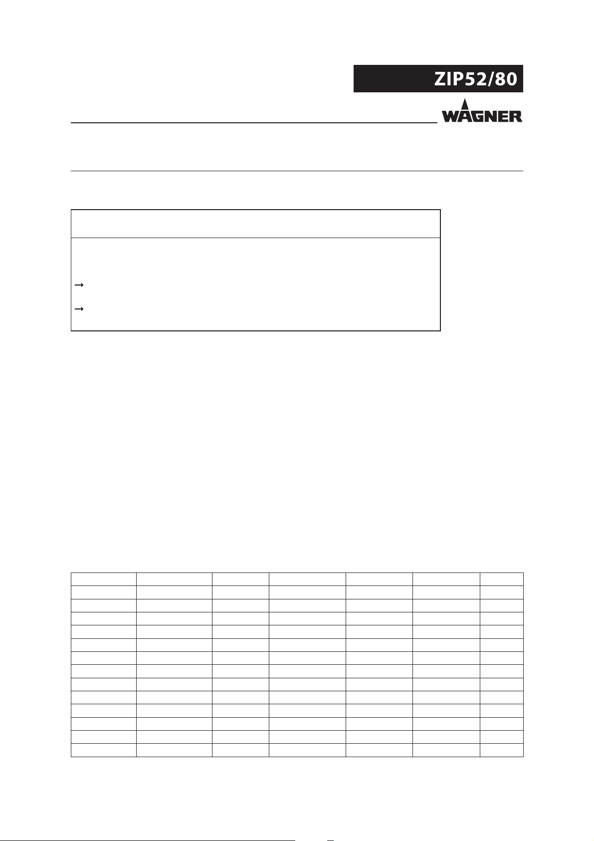
DANGER
Danger - immediate risk of danger.
Non-observance will result in death or serious injury.
Warning - possible imminent danger.
Non-observance may result in death or serious injury.
Caution - a possibly hazardous situation.
Non-observance may result in minor injury.
Notice - a possibly hazardous situation.
Non-observance can cause material damage.
This information warns you of a hazard!
Possible consequences of not observing the warning instructions. The signal word
indicates the hazard level.
The measures for preventing the hazard and its consequences.
This information warns you of a hazard!
Possible consequences of not observing the warning instructions.
The signal word indicates the hazard level.
The measures for preventing the hazard and its
consequences.
WARNING
This information warns you of a hazard!
Possible consequences of not observing the warning instructions.
The signal word indicates the hazard level.
The measures for preventing the hazard and its
consequences.
CAUTION
This information warns you of a hazard!
Possible consequences of not observing the warning instructions.
The signal word indicates the hazard level.
The measures for preventing the hazard and its
consequences.
NOTICE
Note - provides information about particular characteristics and how to proceed.
5
Page 6
VERSION 12/2012 ORDER NUMBER DOC 2330426
OPERATING MANUAL
1.3 LANGUAGES
The operating manual is available in the following languages:
Language: Order No. Language: Order No.
German 2330425 English 2330426
Italian 2332230 French 2335553
Spanish 2335555
1.4 ABBEVIATIONS IN THE TEXT
Number of pieces
Position
Marking in the spare parts lists
Order No. Order number
Double stroke
Materials:
POM Polyoxymethylen (Acetal)
Polypropylene Polypropylene
PPS Polypropylene sul de
PTFE
UHMWPE High molecular weight Polyethylene
Polytetrafl uorethylene
6
Page 7

VERSION 12/2012 ORDER NUMBER DOC 2330426
OPERATING MANUAL
2 CORRECT USE
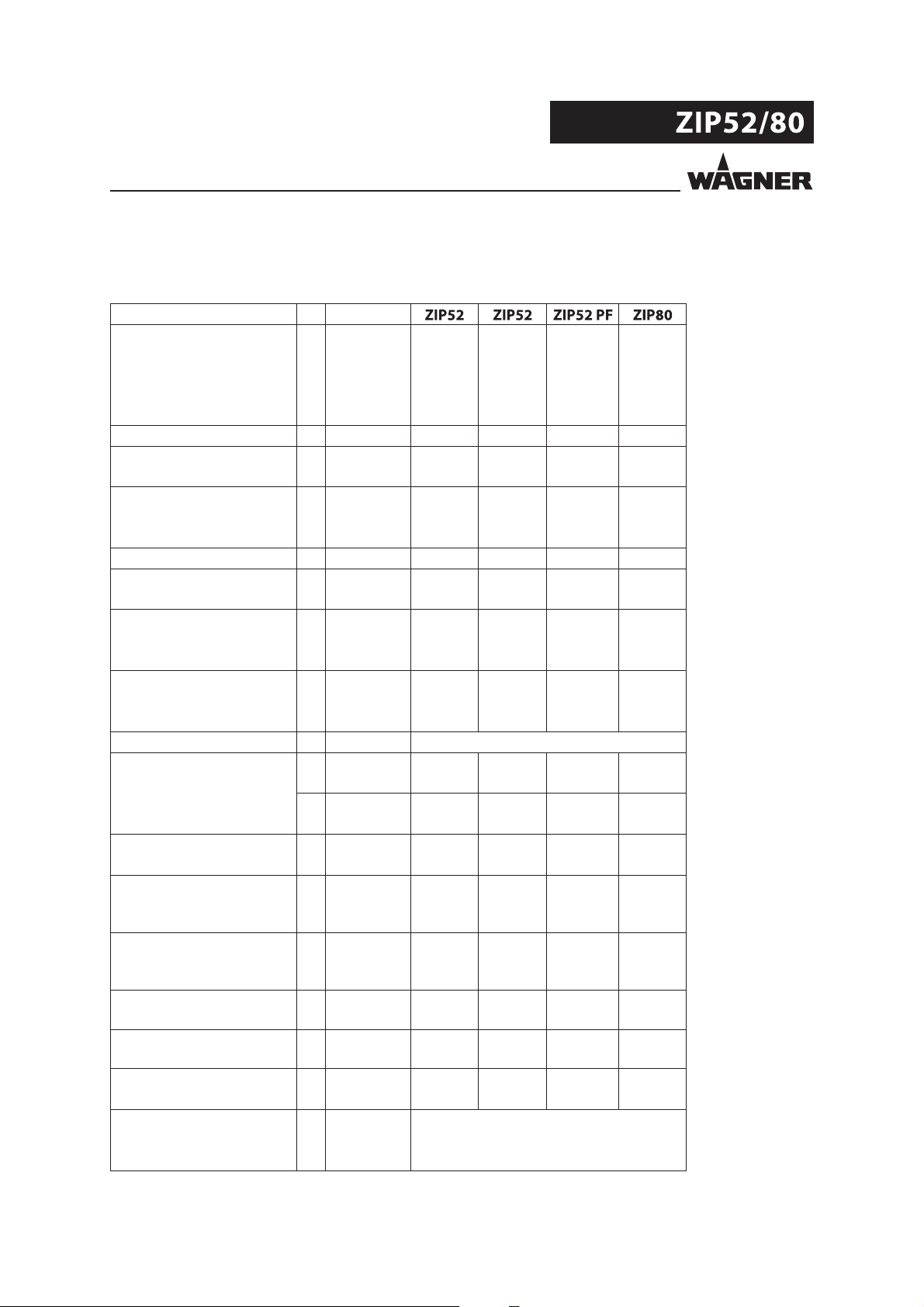
2.1 DEVICE TYPES
A) Metallic versions (aluminum and stainless steel):
Pneumatic double diaphragm pumps with order number
U550.ATRD7 U551.ATSS7 U555.ATSS7
U550.ATSS7 U551.303
U550.ATSS8
U550.STSS7
B) Conductive Acetal versions:
Pneumatic double diaphragm pumps with order number
U552.GHSS1 U553.GTSS1
U552.GHSS7
C) Non-conductive polypropylene versions:
Pneumatic double diaphragm pumps with order number
U552.PTSS7 U553.PHSD7
U553.PTSS7
2.2 TYPE OF USE
A) Metallic versions (aluminum and stainless steel) and conductive Acetal:
The unit is suitable for working liquid materials like paints and varnishes in accordance
with the classi cation into explosion classes IIA or IIB.
B) Non-conductive polypropylene versions:
The unit is suitable for working liquid materials like paints and varnishes.
2.3 USE IN POTENTIALLY EXPLOSIVE AREAS
A) Metallic versions (aluminum and stainless steel) and conductive Acetal:
The pneumatic double diaphragm pumps can be employed in explosion hazard zones
(Zone 1).
B) Non-conductive polypropylene versions:
The pneumatic double diaphragm pump must be employed outside of explosion hazard
zones.
7
Page 8
VERSION 12/2012 ORDER NUMBER DOC 2330426
OPERATING MANUAL
2.4 SAFETY PARAMETERS
WAGNER accepts no liability for any damage arising from incorrect use.
Use the unit only to work with the materials recommended by WAGNER.
Operate only the entire unit.
Do not deactivate safety xtures.
Use only WAGNER original spare parts and accessories.
The operation of the pneumatic double diaphragm pump may is only allowable under
the following conditions:
The operating sta have previously been trained on the basis of this operating
manual.
The safety regulations listed in this operating manual are observed.
The operating, maintenance and repair information in this operating manual is
observed.
The statutory requirements and accident prevention regulations standard in the
country of use are observed.
2.6 PROCESSING MATERIALS
Fluid materials like paints and varnishes.
NOTICE
Abrasive materials and pigments!
Greater wear of the parts carrying the material.
Use the application-oriented model ( ow rate/cycle, material, valve, etc.) as
indicated in section 5.3.2.
Check if the uids and solvents used are compatible with the pump construction
materials as indicated in section 5.3.1.
8
Page 9
VERSION 12/2012 ORDER NUMBER DOC 2330426
OPERATING MANUAL
2.6 REASONABLY FORESEEABLE MISUSE
The following is prohibited:
coating work pieces which are not grounded,
unauthorized conversions and modi cations to the device,
processing dry or similar coating materials,
using defective components, spare parts or accessories other than those described
in chapter 10 of this operating manual.
The forms of misuse listed below may result in health issues and/or damage to property:
use of powder as coating material
and incorrectly set values for the processing.
Wagner double diaphragm pumps are not designed for pumping food.
2.7 RESIDUAL RISKS
Residual risks are risks which cannot be excluded even in the event of correct use.
If necessary, warning and prohibition signs at the relevant points of risk indicate residual
risks.
Residual risk Source Consequences Speci c measures Lifecycle phase
Skin contact with
paints and cleaning
agents
Paint in air outside
the de ned working
area
Handling of paints
and cleaning agents
Painting outside the
de ned working
area
Skin irritation, Wear protective
clothing
allergies Observe safety data
sheets
Inhalation of
substances which
are hazardous to
health
Observe working
and operating
instructions.
Operation,
maintenance,
disassembly
Operation,
maintenance
9
Page 10
VERSION 12/2012 ORDER NUMBER DOC 2330426
OPERATING MANUAL
3 IDENTIFICATION
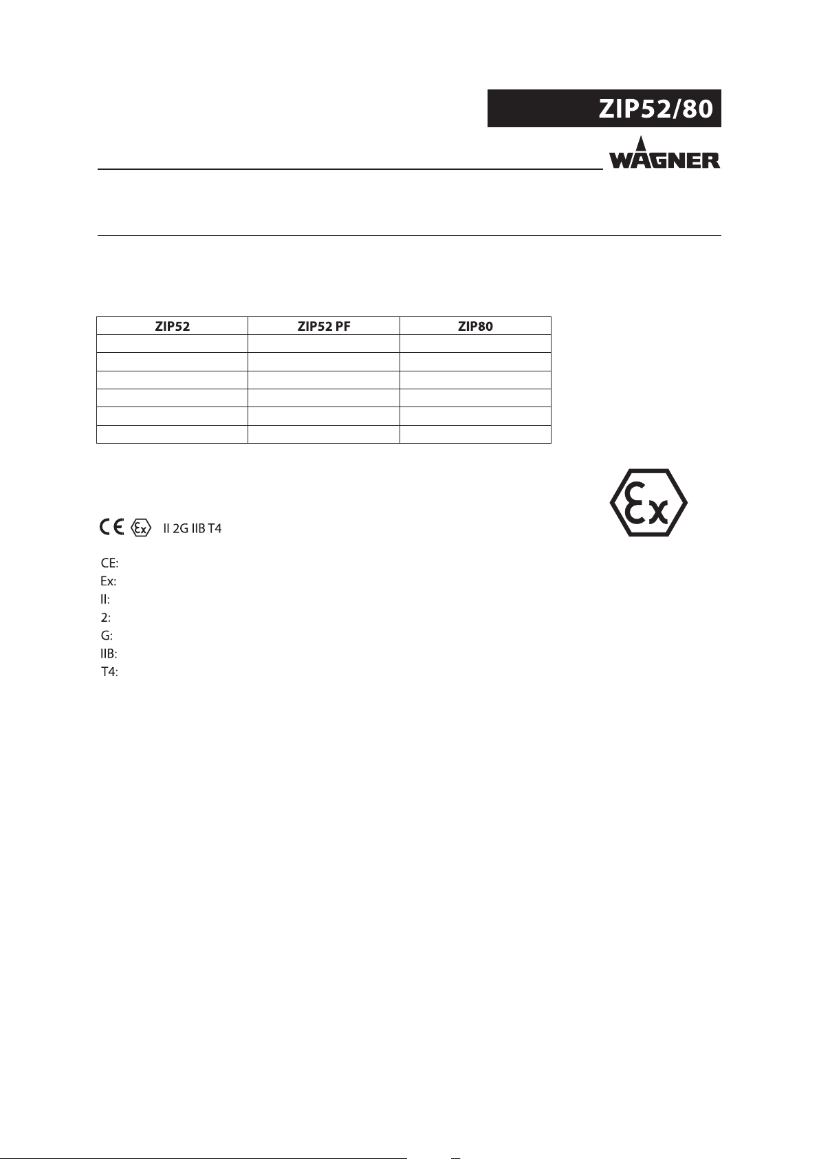
3.1 EXPLOSION PROTECTION IDENTIFICATION
A) Metallic versions (aluminum and stainless steel) and conductive Acetal:
Pneumatic double diaphragm pumps with order number
U550.ATRD7 U551.ATSS7 U555.ATSS7
U550.ATSS7 U551.303
U550.ATSS8 U553.GTSS1
U550.STSS7
U552.GHSS1
U552.GHSS7
As de ned in the Directive 94/9/EC (ATEX 95), the unit is suitable for use in areas where
there is an explosion hazard.
+4°C Tamb +40°C
European Communities
Symbol for explosion protection
Unit class II
Category 2 (Zone 1)
Ex-atmosphere gas
Explosion group
Temperature class: maximum surface temperature < 135 °C; 275 °F
Tamb +4 °C to +40 °C: permissible ambient temperature area
3.2 MAXIMUM SURFACE TEMPERATURE
Maximum surface temperature: the same as the permissible material temperature.
Permissible ambient temperature: see under Technical data, Section 5.3.2.
10
Page 11
VERSION 12/2012 ORDER NUMBER DOC 2330426
OPERATING MANUAL
4 GENERAL SAFETY INSTRUCTIONS
4.1 SAFETY INSTRUCTIONS FOR THE OPERATOR
Keep this operating manual at hand near the device at all times.
Always follow local regulations concerning occupational safety and accident
prevention.
4.1.1 ELECTRICAL EQUIPMENT
Electrical devices and equipment
To be provided in accordance with the local safety requirements with regard to the
operating mode and ambient in uences.
May only be maintained by skilled electricians or under their supervision.
Must be operated in accordance with the safety regulations and electrotechnical
regulations.
Must be repaired immediately in the event of problems.
Must be put out of operation if they pose a hazard.
Must be de-energized before work is commenced on active parts. Inform sta about
planned work. Observe electrical safety regulations.
4.1.2 PERSONNEL QUALIFICATIONS
Ensure that the device is operated and repaired only by trained persons.
4.1.3 SAFE WORK ENVIRONMENT
Make sure that the oor in the area where you are working is electrostatically
conductive in accordance with EN 61340-4-1.
Ensure that all persons within the working area wear electrostatically conductive
shoes.
Ensure that during spraying, persons wear electrically conductive gloves. The
grounding via the handle of the spray gun.
Paint mist extraction systems must be tted on site according to local regulations.
Ensure that the following components of a safe working environment are available:
– material/air hoses adapted to the working pressure.
– Personal safety equipment (breathing and skin protection).
Ensure that there are no ignition sources such as naked ames, sparks, glowing wires
or hot surfaces in the vicinity. Do not smoke.
4.2 SAFETY INSTRUCTIONS FOR STAFF
Always follow the information in these instructions, particularly the general safety
instructions and the warning instructions.
Always follow local regulations concerning occupational safety and accident
prevention.
11
Page 12
VERSION 12/2012 ORDER NUMBER DOC 2330426
OPERATING MANUAL
4.2.1 SAFE HANDLING OF WAGNER SPRAY UNITS
The spray jet is under pressure and can cause dangerous injuries.
Avoid injection of paint or cleaning agents:
Never point the spray gun at people.
Never reach into the spray jet.
Before all work on the device, in the event of work interruptions and functional faults:
- Switch o the energy/compressed air supply.
- Secure the spray gun against actuation.
- Relieve the pressure from the spray gun and unit.
- In case of functional faults: Identify and correct the problem, proceed as described in
Chapter "Trouble Shooting".
The liquid emitters are to be checked for safe working conditions by an expert (e.g.
Wagner Service Technician) as often as necessary or at least every 12 months, in
accordance with the guidelines for liquid emitters (ZH 1/406 and BGR 500 Part 2
Chapter 2.36).
- For shut down devices, the examination can be suspended until the next start-up.
In the event of skin injuries caused by paint or cleaning agents:
Note down the paint or cleaning agent that you have been using.
Consult a doctor immediately.
Avoid danger of injury through recoil forces:
Ensure that you have a firm footing when operating the spray gun.
Only hold the spray gun brie y in a position.
4.2.2 GROUNDING THE UNIT EXCEPT FOR NONCONDUCTIVE PLASTIC UNITS
Depending on the electrostatic charge and the ow speed of the spray, an electrostatic
charge may occur in the equipment. In the event of discharge, this may result in the
formation of sparks or ames.
Ensure that the unit is grounded for every spraying operation.
Ground the work pieces to be coated.
Ensure that all persons inside the working area are grounded, e.g. that they are wearing
electrostatically conductive shoes.
Wear electrostatically conductive gloves when spraying. The grounding via the spray
gun handle.
4.2.3 MATERIAL HOSES
Ensure that the hose material is chemically resistant to the sprayed materials.
Ensure that the material hose is suitable for the pressure generated in the unit.
Make sure that the hoses are laid only in suitable places. In no case, should hoses be
laid in the following places:
– in high traffic areas,
– on sharp edges,
– on moving parts or
– on hot surfaces.
Make sure that the hoses are never used to pull or move the equipment.
The electrical resistance of the complete high pressure hose must be less than 1MOhm.
12
Page 13
VERSION 12/2012 ORDER NUMBER DOC 2330426
OPERATING MANUAL
Several liquids have a high expansion coe cient. In some cases its volume can rise with
consequent damage to hoses, ttings and cause uid leakage.
When the pump sucks liquid from a closed container, ensure that air or suitable gas can
enter the container to avoid a vacuum being generated in the container itself. So that a
negative pressure is avoided. The vacuum could implode the container (squeeze) and can
break. The container would leak and the liquid ow out.
The pressure ratio is 1:1. Therefore the pressure generated by the pump is equal to the
input air pressure.
4.2.4 CLEANING
De-energize the unit electrically.
Disconnect the pneumatic supply line.
Relieve the pressure from the unit.
Ensure that the flash point of the cleaning agent is at least 5 K above the ambient
temperature.
To clean, use cloths and brushes moistened with solvent. Never use hard objects or
spray on cleaning agents with a gun.
An explosive gas/air mixture forms in closed containers.
When cleaning units with solvents, never spray into a closed container.
Ground the container.
4.2.5 HANDLING HAZARDOUS LIQUIDS, VARNISHES AND PAINTS
When preparing or working with paint and when cleaning the unit, follow the working
instructions of the manufacturer of the paints, solvents and cleaning agents being
used.
Take the speci ed protective measures, in particular wear safety goggles, protective
clothing and gloves, as well as hand protection cream if necessary.
Use a mask or a breathing apparatus if necessary.
For su cient health and environmental safety: Operate the unit in a spray booth or on
a spraying wall with the ventilation (extraction) switched on.
Wear suitable protective clothing when working with hot materials.
4.2.6 TOUCHING HOT SURFACES
Touch hot surfaces only if you are wearing protective gloves.
When operating the unit with a coating material with a temperature of > 43 °C; 109.4°F:
- Identify the unit with a warning sticker "Warning - hot surface".
Order No.
9998910 Instruction sticker
9998911 Protection sticker
Note: The two stickers order together.
13
Page 14

VERSION 12/2012 ORDER NUMBER DOC 2330426
OPERATING MANUAL
4.2.7 EXPLOSION HAZARD
Do not ever use chloride or halogenated solvents (such as trichlorothane and methylene
chloride) with units containing aluminum or galvanized and zinc-plated parts. As they may
react chemically thus producing an explosion danger.
Read the classi cation and information lea et concerning the product and solvent to be
used.
4.2.8 NOISE RISK
In some working conditions, the pump can be particularly noisy: for example when the
air feeding pressure is high and when there is no pressure or a very low pressure in the
pumped uid (free ow operation). In these cases, all personnel working next to the pump
shall wear adequate individual protections and/or use valves and seats in plastic material,
provided the working conditions and the compatibility with the pumped uid allow it.
4.2.9 MATERIAL CHEMICAL COMPATIBILITY
Make sure the materials employed in manufacturing the pump are chemically compatible
with the uid to be pumped. A wrong choice can cause harming people (as a result of
prosection of noxious and irritant products) as well as polluting the environment, besides
prematurely damaging the pump and its hoses.
4.2.10 EMERGENCY STOP
To quickly stop the unit in case of emergency, close the air cuto valve or the pressure
regulator; to interrupt the air supply to the pump’s motor. Cuto valve is not supplied with
the pump. It has to be provided and properly installed by the user.
Caution: delivery circuits of pneumatic pumps can remain pressurized, even when the air
input valve is closed.
4.2.11 TIGHTNESS CHECK
When using the pump after a long period of inactivity, check tightness of all parts subject
to pressure.
4.2.12 MAINTENANCE
Depending on the type of use and the substances used, the user has to periodically check
for presence of deposits as well as its cleanliness, the state of wear of the components and
proper operation of the pump assembly.
The operation has to be carried out in conformity with what is written in this manual.
14
Page 15
VERSION 12/2012 ORDER NUMBER DOC 2330426
OPERATING MANUAL
4.3 USE IN AREAS SUBJECT TO EXPLOSION HAZARDS
Only the pneumatic double diaphragm pump in metal (aluminum and stainless steel) and
conductive Acetal can be used in explosion hazard zones. The following safety regulations
must be observed and followed.
4.3.1 SAFETY REGULATIONS
Safe handling of WAGNER spray units
Mechanical sparks can form if the unit comes into contact with metal.
In an explosive atmosphere:
Do not knock or push the unit against steel or rusty iron.
Do not drop the unit.
Use only tools that are made of a permitted material.
Ignition temperature of the pumped material
Check that the ignition temperature of the pumped material is higher than the max.
allowable surface temperature.
Medium supporting atomizing
To atomize the material, use only weakly oxidizing gases, e.g. air.
Surface spraying, electrostatic
Do not spray system parts with electrostatic.
Cleaning
If there are deposits on the surfaces, the unit may form electrostatic charges. Flames or
sparks can form if there is a discharge.
Remove deposits from the surfaces to maintain conductivity.
Use only a damp cloth to clean the unit.
15
Page 16

VERSION 12/2012 ORDER NUMBER DOC 2330426
OPERATING MANUAL
4.3.2 OPERATION WITHOUT FLUID
Avoid running the pump sucking air, without uid inside. The air, combined with the
vapour of ammable uids, can generate internal areas with an explosion hazard.
Periodically check that the pump is working regularly, paying special attention to presence
of air in the pumped uid, which may be caused by a breakage in the pump.
Avoid operating the pump with damaged diaphragms.
4.3.3 MAXIMUM SURFACE TEMPERATURE
The maximum surface temperature of the pump depends on the temperature of the
pumped uid, that must not exceed the values indicated in the section "Technical Data".
4.3.4 MAXIMUM SURFACE TEMPERATURE EXOTHERMIC REACTIONS
Fluids incompatible with the pump’s materials or particularly reactive mixtures of products
with several components may cause exothermic reactions and develop dangerous
temperatures or pressure.
4.3.5 CONNECTION PIPES
Connection cables must be made of conductive material and properly grounded.
4.3.6 PUMP PROTECTION
If the pumping uids contain solid particles, install a lter on the intake circuit. This
prevents particles, that are large enough to damage the internal parts of the pump, from
entering. Refer to the paragraph Technical Data to verify the maximum size of solids that
can be pumped.
Keep the metal surfaces clean. Electric conductivity of the surfaces is essential for explosion
protection.
Frequently clean the equipment so as to prevent residue of insulating substances from
accumulating.
Do not use rusted parts or metal tools that may cause sparks of a mechanical origin inside
the explosion hazard area.
16
Page 17
VERSION 12/2012 ORDER NUMBER DOC 2330426
OPERATING MANUAL
5 DESCRIPTION
5.1 AREAS OF APPLICATION
NOTICE
Abrasive materials and pigments!
Greater wear of the parts carrying the material.
Use the application-oriented model ( ow rate/cycle, material, valve, etc.) as
indicated in section 5.3.2.
Check if the uids and solvents used are compatible with the pump construction
materials as indicated in section 5.3.1.
5.2 SCOPE OF DELIVERY
- Diaphragm pump
CE-Conformity See Chapter 12
Operating manual German Order No.: 2330425
Operating manual for other languages See Chapter 1
The delivery note shows the exact scope of delivery.
Accessories: see Chapter 10
5.3 DATA
5.3.1 MATERIALS OF THE FLUID TRANSPORTING PARTS
Pump No. Pump body Diaphragm Diaphragm disc Valve seat Valve ball O-rings
U550.ATRD7 Aluminum PTFE PPS PPS Acetal (POM) PTFE
U550.ATSS7 Aluminum PTFE PPS Stainless steel Stainless steel PTFE
U550.ATSS8 Aluminum PTFE PPS Stainless steel Stainless steel PTFE
U550.STSS7 Stainless steel PTFE PPS Stainless steel Stainless steel PTFE
U551.ATSS7 Aluminum PTFE PPS Stainless steel Stainless steel PTFE
U551.303 Aluminum PTFE PPS Stainless steel Stainless steel PTFE
U552.GHSS1 Acetal (POM) UHMWPE POM Stainless steel Stainless steel PTFE
U552.GHSS7 Acetal (POM) UHMWPE POM Stainless steel Stainless steel PTFE
U552.PTSS7 Polypropylene PTFE Polypropylene Stainless steel Stainless steel PTFE
U553.GTSS1 Acetal (POM) PTFE POM Stainless steel Stainless steel PTFE
U553.PHSD7 Polypropylene UHMWPE Polypropylene Stainless steel Acetal (POM) PTFE
U553.PTSS7 Polypropylene PTFE Polypropylene Stainless steel Stainless steel PTFE
U555.ATSS7 Aluminum PTFE PPS Stainless steel Stainless steel PTFE
Positions of the individual parts: see spare parts list.
17
Page 18
VERSION 12/2012 ORDER NUMBER DOC 2330426
OPERATING MANUAL
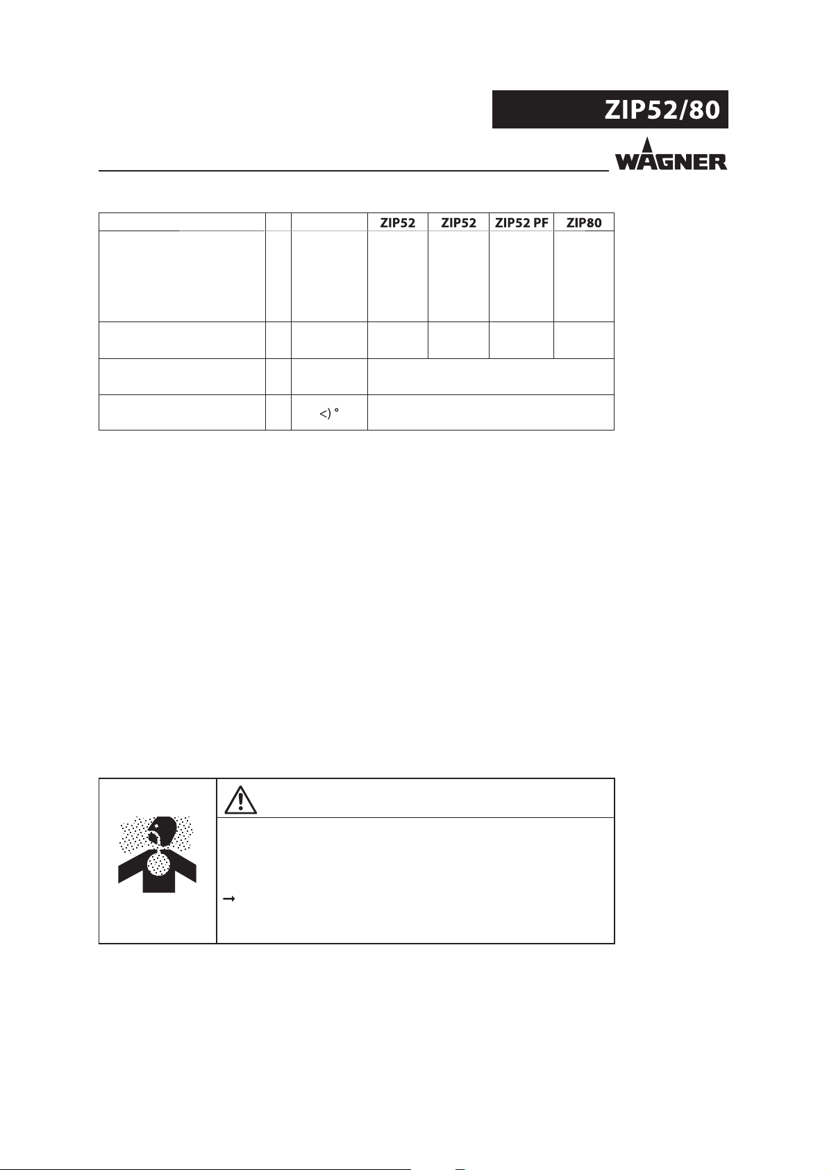
5.3.2 TECHNICAL DATA
5.3.2.1 TECHNICAL DATA FOR METALLIC PUMPS
Description Unit
Wetted parts materials
Aluminum
Transmission ratio 1:1 1:1 1:1 1:1
Flow volume per double
stroke (DH)
Maximum operating
pressure
Maximum possible speed DH/min 490 490 490 360
Maximum ow rate
(free ow - ooded inlet) GPM 13.7 13.7 7.4 21.1
Minimum air inlet pressure MPa 0.15 0.15 0.10 0.22
Maximum air inlet pressure MPa 0.8 0.8 0.8 0.8
Air inlet connection (male) BSP(R) 1/4"
Maximum suction height
Maximum solid body size mm 2.0 2.0 2.0 3.0
Sound pressure equivalent
50 cycles/min
(feeding 5bar)
Sound pressure equivalent
maximum ow rate
(feeding 8 bar)
Sound power at maximum
ow rate (feeding 8 bar)
Fluid connections
(inlet & outlet bush)
Weight kg 3.7 6.0 3.7 5.3
Maximum material
pressure at the pump's
inlet
(1)
(2)
(3)
(4) dB(A) 73 73 73 79
(4) dB(A) 85 85 85 91
(5) dB(A) 99 99 99 102
cm³ 108 108 62 225
cc
MPa 0.8 0.8 0.8 0.8
bar 8 8 8 8
psi 116 116 116 116
l/min 52 52 28 80
bar 1.5 1.5 1.0 2.2
psi 22 22 15 32
bar 8 8 8 8
psi 116 116 116 116
m 4.8 4.8 2.8 4.9
ft 15.7 15.7 9.2 16
m 2.7 2.7 2.2 2.7
ft 9 9 7.2 9
inches 0.08 0.08 0.08 0.12
BSP(G) 1/2" 1/2" 1/2" 3/4"
lb 8.1 13.2 8.1 11.7
MPa 0.1
bar 1
psi 14.5
Stainless steel
Aluminum
Aluminum
18
Page 19
VERSION 12/2012 ORDER NUMBER DOC 2330426
OPERATING MANUAL
Description Unit
Wetted parts materials
Aluminum
Material temperature °C +4÷90 +4÷90 +4÷90 +4÷90
°F +39÷194 +39÷194 +39÷194 +39÷194
Ambient temperature °C +4 ÷ +40
°F +39 ÷ +104
Allowable sloping position
for operation
(1) PF = Perfect Flow = low pulsation pump with a shorter stroke
(2) Pump with stainless steel valves (start condition: empty pump / dry valves)
(3) Pump with plastic valves (start condition: empty pump / dry valves)
(4) LqA (10s)
(5) (ISO 3744
Stainless steel
10°
Aluminum
Aluminum
WARNING
Outgoing air containing oil!
Risk of poisoning if inhaled.
Air motor switching problems.
Provide compressed air free from oil and water (quality standard
5.5.4 according to ISO 8573.1)
5.5.4 = 40 μm / +7 / 5 mg/m³.
19
Page 20
VERSION 12/2012 ORDER NUMBER DOC 2330426
OPERATING MANUAL
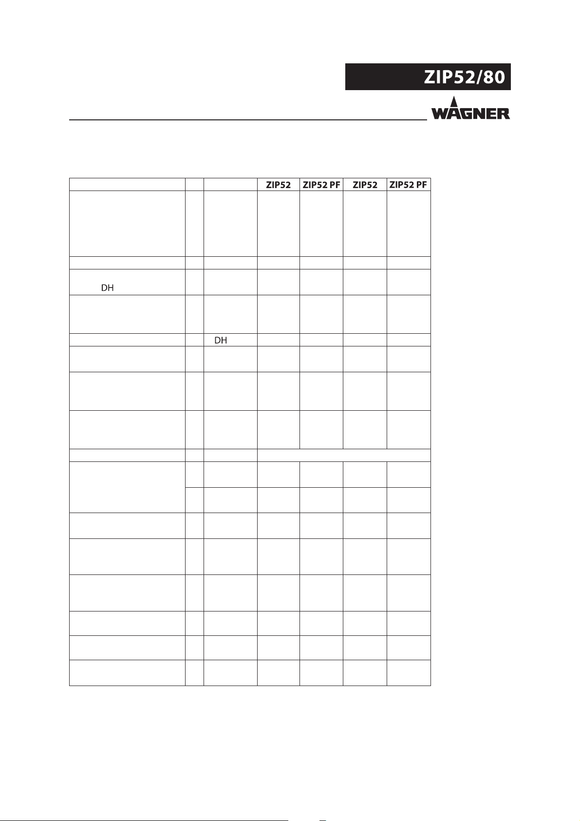
5.3.2.2 TECHNICAL DATA FOR NONMETALLIC PUMPS
Description Unit
Wetted parts materials
Polypropylene
Transmission ratio 1:1 1:1 1:1 1:1
Flow volume per double
stroke ( )
Maximum operating
pressure
Maximum possible speed /min 490 490 490 490
Maximum ow rate
(free ow - ooded inlet) GPM 13.7 7.4 13.7 7.4
Minimum air inlet pressure MPa 0.15 0.10 0.15 0.10
Maximum air inlet pressure MPa 0.8 0.8 0.8 0.8
Air inlet connection (male) BSP(R) 1/4"
Maximum suction height
Maximum solid body size mm 2.0 2.0 2.0 2.0
Sound pressure equivalent
50 cycles/min
(feeding 5bar)
Sound pressure equivalent
maximum ow rate
(feeding 8 bar)
Sound power at maximum
ow rate (feeding 8 bar)
Fluid connections
(inlet & outlet bush)
Weight kg 3.2 3.2 3.2 3.2
(1)
(2)
(3)
(4) dB(A) 73 73 73 73
(4) dB(A) 85 85 85 85
(5) dB(A) 99 99 99 99
cm³ 108 62 108 62
cc
MPa 0.8 0.8 0.8 0.8
bar 8 8 8 8
psi 116 116 116 116
l/min 52 28 52 28
bar 1.5 1.0 1.5 1.0
psi 22 15 22 15
bar 8 8 8 8
psi 116 116 116 116
m 4.8 2.8 4.8 2.8
ft 15.7 9.2 15.7 9.2
m 2.7 2.2 2.7 2.2
ft 9 7.2 9 7.2
inches 0.08 0.08 0.08 0.08
BSP(G) 1/2" 1/2" 1/2" 1/2"
lb 7.1 7.1 7.1 7.1
Polypropylene
Conductive
Acetal
Conductive
Acetal
20
Page 21

VERSION 12/2012 ORDER NUMBER DOC 2330426
OPERATING MANUAL
Description Unit
Wetted parts materials
Polypropylene
Maximum material
pressure at the pump's
inlet
Material temperature °C +4÷60 +4÷60 +4÷80 +4÷80
Ambient temperature °C +4 ÷ +40
Allowable sloping position
for operation
(1) PF = Perfect Flow = low pulsation pump with a shorter stroke
(2) Pump with stainless steel valves (start condition: empty pump / dry valves)
(3) Pump with plastic valves (start condition: empty pump / dry valves)
(4) LqA (10s)
(5) ISO 3744
MPa 0.1
bar 1
psi 14.5
°F +39÷140 +39÷140 +39÷176 +39÷176
°F +39 ÷ +104
Polypropylene
10°
Conductive
Acetal
Conductive
Acetal
WARNING
Outgoing air containing oil!
Risk of poisoning if inhaled.
Air motor switching problems.
Provide compressed air free from oil and water (quality standard
5.5.4 according to ISO 8573.1)
5.5.4 = 40 μm / +7 / 5 mg/m³.
21
Page 22

VERSION 12/2012 ORDER NUMBER DOC 2330426
OPERATING MANUAL
5.3.3 DIMENSIONS AND CONNECTIONS
AB
J
J
D
C
J
J
EF
GH
B_04007
J
J
J
K
Wall mount
S = E + (2 x N)
N
O
E
P
Q
R
M
B_04028
M
22
Page 23

VERSION 12/2012 ORDER NUMBER DOC 2330426
OPERATING MANUAL
Aluminum Stainless steel Polypropylene
and
conductive
Acetal
mm; inch mm; inch mm; inch mm; inch mm; inch mm; inch
200.5; 7.89 210.0; 8.27 205.0; 8.07 200.5; 7.89 205.0; 8.07 220.0; 8.66
147.5; 5.80 147.5; 5.80 149.0; 5.86 147.5; 5.80 149.0; 5.86 174.5; 6.87
231.0; 9.09 232.5; 9.15 236.0; 9.29 231.0; 9.09 236.0; 9.29 277.5; 10.92
184.0; 7.24 184.0; 7.24 191.0; 7.52 184.0; 7.24 191.0; 7.52 220.5; 8.68
155.0 - 161.0; 157.5 - 163; 154.0 - 162.0 155.0 -161.0; 154.0 - 162.0 ; 168.0 - 174.0;
6.10 - 6.34 6.20 - 6.42 6.06 - 6.38 6.10 - 6.34 6.06 - 6.38 6.61 - 6.85
86.0; 3.38 86.0; 3.38 87.0; 3.42 86.0; 3.38 87.0; 3.42 95.0; 3.74
192.5; 7.58 188; 7.40 187.0; 7.36 192.5; 7.58 187.0; 7.36 205.5; 8.09
100.0; 3.94 100.0; 3.94 101.0; 3.97 100.0; 3.94 101.0; 3.97 110.0; 4.33
G1/2" (BPS) F G3/4" (BPS) F
R1/4" (BSPT) M
ø9.0; ø0.35
37.5; 1.48
80.0; 3.15
Aluminum Polypropylene
and
conductive
Acetal
189; 7.4
98; 3.85
83; 3.27
Aluminum
23
Page 24

VERSION 12/2012 ORDER NUMBER DOC 2330426
OPERATING MANUAL
5.3.4 PERFORMANCE DIAGRAMS
Example
BAR
BAR
Diagram ZIP52
Material pressure bar (MPa) <psi>
Material pressure
BAR
BAR
"?
bar (MPa)
<psi>
10 (1.0)
<145>
8.0 (0.8)
<116>
6.0 (0.6)
<87>
4.0 (0.4)
<58>
2.0 (0.2)
<29>
Material ow volume - water l/min <gpm>
A
B
C
A
B
C
BAR
BAR
750
<26.9>
600
<21.4>
450
<16.1>
300
<10.7>
150
<5.4>
Air consumption nl/min <scfm>
nl/min
<scfm>
Air consumption
0 0
40
<2.64>
<5.28>
20
10
0
30
<7.92>
<10.56>
Material ow volume - water
A = 8 bar; 0.8 MPa; 116 psi air pressure
B = 6 bar; 0.6 MPa; 87 psi air pressure
C = 4 bar; 0.4 MPa; 58 psi air pressure
The chart above refers to the aluminium version with stainless steel valves.
50
<13.21>
60
<15.85>
l/min
<gpm>
24
Page 25

VERSION 12/2012 ORDER NUMBER DOC 2330426
OPERATING MANUAL
Diagram ZIP52 PF
bar (MPa)
<psi>
10 (1.0)
<145>
8.0 (0.8)
<116>
6.0 (0.6)
<87>
4.0 (0.4)
<58>
Material pressure
2.0 (0.2)
<29>
A
B
C
0 0
0
5
<1.32>
10
<2.64>
15
<3.96>
Material ow volume - water
C
20
<5.28>
B
A
<6.60>
25
30
<7.92>
nl/min
<scfm>
250
<8.9>
200
<7.1>
150
<5.4>
100
<3.6>
50
<1.8>
l/min
<gpm>
Air consumption
A = 8 bar; 0.8 MPa; 116 psi air pressure
B = 6 bar; 0.6 MPa; 87 psi air pressure
C = 4 bar; 0.4 MPa; 58 psi air pressure
The chart above refers to the aluminium version with stainless steel valves.
Diagram ZIP80
bar (MPa)
<psi>
10 (1.0)
<145>
8.0 (0.8)
<116>
6.0 (0.6)
<87>
4.0 (0.4)
<58>
2.0 (0.2)
Material pressure
<29>
A
B
C
0 0
60
0
15
<3.96>
30
<7.92>
45
<11.88>
<15.85>
B
C
<19.80>
A
75
90
<23.76>
nl/min
<scfm>
750
<26.9>
600
<21.4>
450
<16.1>
300
<10.7>
150
<5.4>
l/min
<gpm>
Air consumption
Material ow volume - water
A = 8 bar; 0.8 MPa; 116 psi air pressure
B = 6 bar; 0.6 MPa; 87 psi air pressure
C = 4 bar; 0.4 MPa; 58 psi air pressure
The chart above refers to the aluminium version with stainless steel valves.
25
Page 26

VERSION 12/2012 ORDER NUMBER DOC 2330426
OPERATING MANUAL
5.4 MODE OF OPERATION
C
C
B
A
A
P
P
M
M
C
C
B_04006
Double diaphragm pump - operating principle
The double diaphragm pump is driven with compressed air.
Two diaphragms (A) are mechanically connected to each other by means of a shaft (B).
Each diaphragm generates two chambers: pumping chamber (P) and motor chamber (M).
A pneumatic distributor alternately supplies compressed air into one of the driving
chambers (M), thus producing the diaphragms movement and consequently causing one
of the pumping chambers (P) to empty (as a result of volume decrease), while at the same
time the other chamber (P) sucks the uid in (as a result of volume increase). A series of four
check valves (C) prevents the liquid from owing back, thus producing the suction and
delivery phases in each pumping chamber, and generating the pumping e ect.
The ZIP models are equipped with an internal safety valve that opens when the maximum
allowed value of air pressure supply is exceeded.
WARNING
Overpressure!
Risk of injury from bursting components.
Never change the safety valve setting.
26
Page 27

VERSION 12/2012 ORDER NUMBER DOC 2330426
OPERATING MANUAL
6 ASSEMBLY AND COMMISSIONING
6.1 TRANSPORTATION
The pump may be moved manually, without lifts and cranes.
6.2 STORAGE
Store the pump in a closed and dry environment.
Thoroughly clean the pump, if a long-term decommissioning is planned.
When resuming pump operation, proceed as described in the following sections.
WARNING
Discharge of electrostatically charged components in atmospheres
containing solvents!
Explosion hazard from electrostatic sparks.
Clean the pump only with a damp cloth.
6.3 ASSEMBLY
Install the pump on a at and horizontal foundation and screw it on tightly.
Ensure that all xing screws (diaphragm covers, manifold, covers) are correctly tightened.
Tighten the xing screws regularly depending on pump use. In the case of continuous
or prolonged operation, it is advisable to check at least once a week that there are no air
and/or liquid leaks.
B_04010
WARNING
Oblique ooring!
Risk of accidents if the unit rolls away/falls.
Place the frame with the pump horizontally.
Secure frame.
27
Page 28

VERSION 12/2012 ORDER NUMBER DOC 2330426
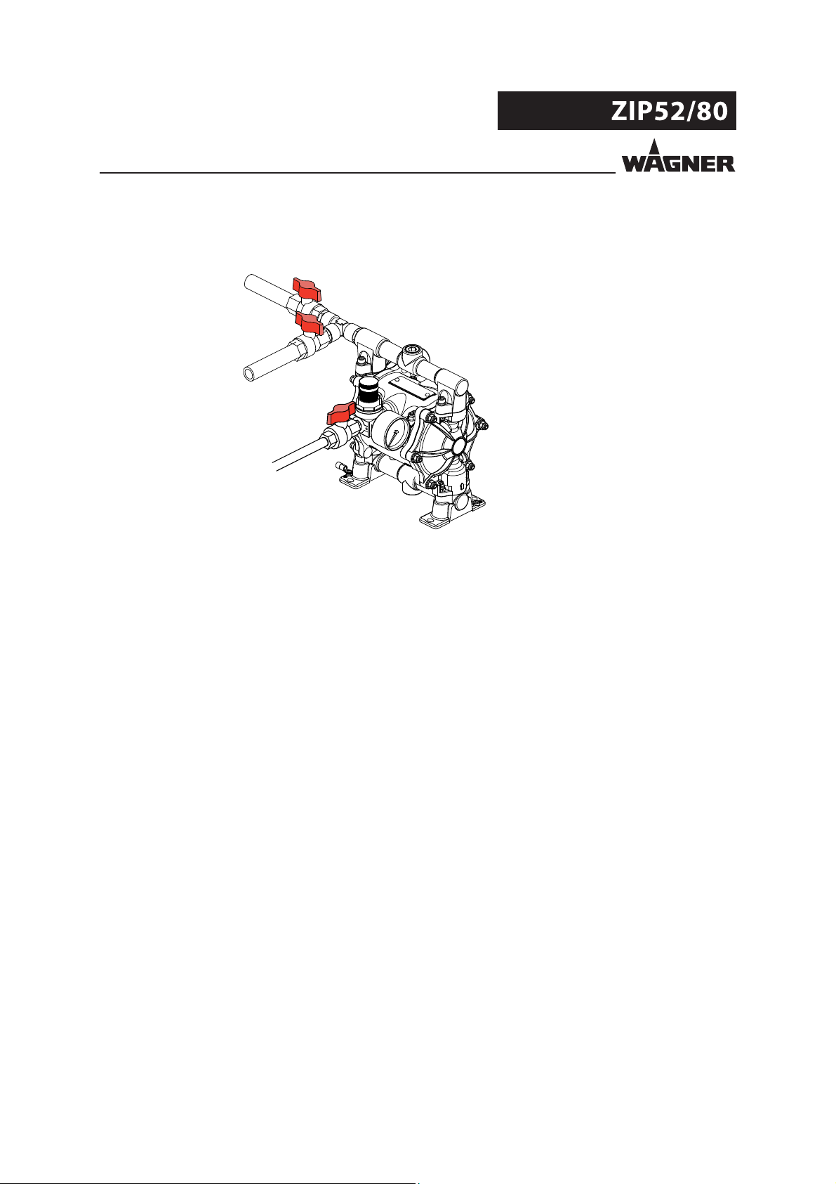
OPERATING MANUAL
Material delivery valve
Material hose
Material return valve
Air pressure regulator
Air cuto valve
Suction hose
Air suction lter
B_04008
Material connection:
On the suction manifold of the pump (bottom) connect the suction hose. On the delivery
manifold (top) connect the material hose. Use exible hoses to absorb the pump's
vibrations. Ensure that the hoses are not mechanically stressing the pump. Never connect
the pump with rigid pipes.
For pumps installed in areas subject to explosion hazards, all hoses and pipes must be
made of conductive material and must be grounded.
Install a suction lter on the suction hose. This prevents particles, that are large enough to
damage the internal parts of the pump, from entering. Refer to the paragraph Technical
Data to verify the maximum size of solids that can be pumped.
Delivery manifold
Suction manifold
28
Page 29

VERSION 12/2012 ORDER NUMBER DOC 2330426
OPERATING MANUAL
All hoses and components connected to the supply line must be able to operate at the
pump’s maximum pressure with the pump working at a pulsating pressure.
All items connected to the suction manifold must not get crushed as a result of the
depression produced by the pump.
The suction and delivery hoses and pipes must have a cross-section proportionate to the
ow rate and the viscosity of the pumped uid. Avoid long and winding pipes, especially
in the suction.
B_04011
Air inlet connection:
The driving air pipe must be properly dimensioned.
Connect the compressed air supply to the pump to the pressure distribution network.
The connection must be carried out on the tting on the pump. Do not replace the
original connection.
Use a pipe with a suitable diameter for the connection.
Always install an air cuto valve and an air processing unit ( lter/regulator unit).
The pressure must not exceed the maximum value indicated on the plate.
Air pressure quality:
The pneumatic motor must be supplied with clean and dry industrial air. Make sure e cient
lter and condensation separation systems are installed on the air line.
The pump can run with non-lubricated air.
Air pressure quality: 5.5.4 = 40 μm / +7 / 5 mg/m³
Reversing valve:
The reversing valve of the pump is lubricated at the factory and does not need any
lubrication.
Safety valve:
The ZIP models are equipped with an internal safety valve that opens when the maximum
allowed value of air pressure supply is exceeded.
Back-pressure valve:
If the pump has been installed on a higher level than the liquid to be pumped, it is
recommended that a back-pressure valve be provided at the lower end of the suction pipe.
29
Page 30

VERSION 12/2012 ORDER NUMBER DOC 2330426
OPERATING MANUAL
6.4 GROUNDING EXCEPT FOR NONCONDUCTIVE PLASTIC UNITS
WARNING
Discharge of electrostatically charged components in atmospheres
containing solvents!
Explosion hazard from electrostatic sparks.
Clean the pump only with a damp cloth.
WARNING
Heavy paint mist if grounding is insu cient!
Danger of poisoning.
Insu cient paint application quality.
Ground all device components.
Ground the work pieces to be coated.
Grounding schema (example)
Conveyor
Work piece
Spraying stand
R max < 1 M Ω
B_00304
Paint container
Electrostatically conductive ooring
30
Page 31

VERSION 12/2012 ORDER NUMBER DOC 2330426
OPERATING MANUAL
The ground connection is at the pumps of metal and conductive acetal imperative.
Note: Pump of nonconductive plastic have no ground connection.
B_04001
Procedure:
1. Remove the crimp connection delivered with the pump.
2. Crimp the grounding cable on the terminal and screw it back onto the pump’s foot.
3. Ground the material/paint container to a local ground connection.
4. Ground the other parts of the system to a local ground connection.
31
Page 32

VERSION 12/2012 ORDER NUMBER DOC 2330426
OPERATING MANUAL
6.5 COMMISSIONING
6.5.1 SAFETY REGULATIONS
Every time before starting up the following points should be observed as laid down in
the operating instructions:
- Observe all safety regulations in accordance with chapter 4.
- Carry out commissioning properly.
WARNING
High pressure spray jet!
Danger to life from injecting paint or solvent.
Never reach into the spray jet.
Never point the spray gun at people.
Consult a doctor immediately in the event of skin injuries caused
by paint or solvent. Inform the doctor about the paint or solvent
used.
Never seal defective high pressure parts, instead relieve the
pressure from them and replace them.
WARNING
Toxic and/or ammable vapor mixtures!
Risk of poisoning and burns.
Operate the unit in a spray booth approved for the working
materials.
-or Operate the unit on an appropriate spraying wall with the
ventilation (extraction) switched on.
Observe national and local regulations for the outgoing air
speed.
WARNING
Gas mixtures can explode if there is an incompletely filled pump!
Danger to life from flying parts.
Ensure that the pump and suction system are always completely
filled with cleaning agent or working medium.
Do not spray the unit empty after cleaning.
Emergency stop
In the case of unforeseen occurrences close the air cut-o valve immediately and open the
return valve (if installed) and/or delivery devices (valves or guns).
32
Page 33

VERSION 12/2012 ORDER NUMBER DOC 2330426
OPERATING MANUAL
6.5.2 PRELIMINARY OPERATIONS
Preliminary ushing
The pump was tested with oil or other uids, depending on the model.
Before use, it is necessary to wash the pump once using an adequate solvent.
Ensure that:
- The pressure regulator knob is turned fully counterclockwise (0 bar pressure).
- The air cuto valve is closed.
- The material delivery valve and the return valve, if installed, are opened.
Delivery
Opened
Discharge
(Return line)
Closed
Air
Open the air cuto valve and turn the regulator knob clockwise until the pump starts.
Delivery
Opened
Discharge
(Return line)
Opened
Opened
B_04012
Opened
Air
Start-up problems:
If the pump doesn't start up, carry out the following steps:
Close the air cuto valve.
Turn the regulator knob of the air pressure regulator o counterclockwise (0 bar pressure).
Open the air cuto valve for air.
Turn the regulator knob clockwise until the pump starts.
If necessary, repeat the operation several times.
While the pump is priming, don’t exceed with the speed.
B_04013
33
Page 34
VERSION 12/2012 ORDER NUMBER DOC 2330426
OPERATING MANUAL
Close the return valve, if installed.
Delivery
Closed
Discharge
(Return line)
Opened
Air
Let the solvent ow through the pump for 2 or 3 minutes.
Opened
B_04014
6.5.3 UNIT PRESSURE TIGHTNESS TEST
Close the material delivery valve, once the pump is primed.
Gradually increase the pressure until reaching the maximum allowed value for the pump
and the devices connected to it. Ensure that the ttings do not leak.
34
Page 35

VERSION 12/2012 ORDER NUMBER DOC 2330426
OPERATING MANUAL
7 OPERATION
7.1 OPERATION
Suction:
Make sure that the air pressure regulator knob is turned fully counterclockwise (0 bar
pressure).
Open the compressed air and material delivery valve, then increase the air pressure until
the pump starts. While the pump is priming, don’t exceed with the speed.
Return valve:
To facilitate the priming of the pump, open the return valve, if installed.
The return valve is strongly recommended in case of viscous materials or long pipes. Close
the return valve when the suction is nish.
Material delivery:
The pump supplies the material while the material delivery valve is open.
Change the air pressure with the air pressure regulator, in order to achieve the desired
amount respectively pressure of material.
Drawn in air:
In case air accidentally ows into the pump suction inlet, it is necessary to immediately
reduce the compressed air pressure to avoid the pump working at an excessive speed.
Stopping the pump:
To stop the pump, simply close the material delivery valve or any other device installed
(such as dispensing valves or guns) on the delivery line.
7.2 ENDING WORK
At the end of the Work close the air cuto valve. Relieve the pressure in the material line, by
opening the return valve (if installed) or the dispensing device (valve or spray gun).
Dealing with hardening liquids:
In case of hardening liquids such as 2-component mixed resins, the pump, and anything
connected to it, must be thoroughly ushed out at the end of working session with using a
solvent suitable for the type of resin being used. The solvent must be left inside the pump,
until its next use.
7.3 STORAGE OVER LONGER PERIODS OF TIME
When storing the device for longer periods of time it is necessary to thoroughly clean it
and protect it from corrosion. Use a suitable preserving uid, according to the material of
the wetted parts of the pump.
35
Page 36

VERSION 12/2012 ORDER NUMBER DOC 2330426
OPERATING MANUAL
8 TROUBLE SHOOTING AND PROBLEM SOLVING
Problem Cause Remedy
The pump does not
work.
The unit is working (i.e.:
the pump is moving),
but no uid is delivered.
The material ow is
suspended.
The pump supply
decreases during work.
The pump supply
decreases during work,
and tends to stop
completely.
The air motor does not work or
stops.
No pressure indication
(pressure regulator defective).
The delivery line is clogged. Check the delivery line.
Insu cient supply of compressed
air.
The lter in delivery line is clogged
(if installed).
The suction lter is clogged
(if installed).
No uid is available at the pump’s
inlet.
The suction pipe is clogged or
leaking (possibility of sucking air in
from the atmosphere).
The suction pipe is partially
clogged.
Cavitation
(air bubbles in the liquid).
The material check valve doesn't
completely close.
Partial clogging of the delivery line. Check the delivery line.
Deviations of the material
characteristics (like viscosity).
Ice formation inside the air outlet
pipes.
The delivery manifold valves guides
are worn-out.
Close the air cuto valve, increase the
pressure and open the air cuto valve
immediately.
Disconnect compressed air supply brie y or
repair or replace the pressure regulator.
Check the compressed air supply.
Clean or replace the lter.
Carefully clean the lter.
Check the uid level in the tank or
container.
Check the suction pipe. Replace it if
necessary.
Check the suction pipe. Replace it if
necessary.
Check the suction in the tank. Exclude air
intake due to high viscosity.
Check for impurities on the valve seats.
Replace the check valves if necessary.
Check the material characteristics.
Check the compressed air quality.
Install a condensation separator on the air
line.
Install an air dryer if necessary.
Fill one lubricant with special de-icing uid.
Replace the delivery manifold (or in the case
of plastic pumps, replace the insert).
36
Page 37

VERSION 12/2012 ORDER NUMBER DOC 2330426
OPERATING MANUAL
Problem Cause Remedy
The material delivery
valve is closed,
nevertheless the pump
continues to run even
if the supply's air cuto
vale is closed.
If the problem is not listed above consult your WAGNER Service Center.
The material delivery valve or the
delivery manifold leaks.
Dirty or worn-out material check
valves in the delivery and suction
manifold.
Check the material delivery valve and the
seals of the delivery manifold.
Clean the check valves and replace them if
they are worn.
37
Page 38

VERSION 12/2012 ORDER NUMBER DOC 2330426
OPERATING MANUAL
9 MAINTENANCE
WARNING
Incorrect maintenance/repair!
Danger to life and equipment damage.
Only a WAGNER service center or a suitably trained person may
carry out repairs and replace parts.
Only repair and replace parts that are listed in the chapter "Spare
Parts Catalogue" and that are assigned to the unit.
Before all work on the unit and in the event of work interruptions:
- Disconnect the control unit from the mains.
- Relieve the pressure from the spray gun and unit.
- Secure the spray gun against actuation.
Observe the operating and service instructions when carrying
out all work.
1. Check and clean the delivery and suction lters daily or as necessary.
2. Carry out every shut down as explained in paragraph 7.2.
3. As necessary, check and replace hoses, pipes, and connections daily.
In accordance with the guideline for liquid emitters (ZH 1/406 and BGR500 Part 2
Chapter2.3):
- The liquid emitters should be checked by an expert (e.g. Wagner service technician)
for their safe working conditions as required and at least every 12 months.
- For shut down devices, the examination can be suspended until the next start-up.
38
Page 39

VERSION 12/2012 ORDER NUMBER DOC 2330426
OPERATING MANUAL
9.1 SAFETY INSTRUCTIONS
Prior to maintenance and cleaning measures note:
Wear protective clothing and use speci c protection devices with regard to the nature of the uids
involved.
Close the compressed air supply and release the pressure from the pump and pipes connected to it.
Depending on the operation, disconnect the material and air side connection pipes.
Remove the pump from the base or support it is fastened to. Turn the pump upside-down over a container
suitable for collecting any liquid it may contain.
After the pump has been reassembled and reinstalled following maintenance operations:
check the e ciency of the grounding connection of the individual parts of the pump.
Carry out pressure retention test in accordance with chapter 6.5.3. Check that no air ows out.
Note: All threads are right-hand threads.
9.2 DIAPHRAGM REPLACEMENT PREVENTIVE MAINTENANCE
Mark the coupled parts (Diaphragm covers, distributor, covers) with a felt-tip
pen so as to make subsequent reassembly easier.
a) Remove the suction and delivery manifolds.
b) Disassemble the fastening nuts and remove the outer diaphragm
covers. Disassemble the pressure side cover (1).
1
B_04015
B_04066
39
Page 40

VERSION 12/2012 ORDER NUMBER DOC 2330426
OPERATING MANUAL
c) Hald the end nut of an outer diphragm disk with a wrench. Loose the end nut of the other diaphragm
disk and remove.
d) Remove the freed diaphragm with its corresponding internal disc, and remove the shaft from the motor
block.
12 Nm
8.8 lbft
B_04067
e) Lock the end of the shaft released from the diaphragm in a bench vice (provide soft jaws to avoid
damaging it) and disassemble the external diaphragm disc from the opposite end of the shaft. Then
remove the second diaphragm with its internal disk.
f) Assemble the new diaphragm with its internal disc and properly fasten it to the relevant external disc.
g) Remove the shaft from the bench vice and put it in the motor block. Grease the shaft inside and outside
(beyond the underside of the motor block. Thereby move the shaft in di erent positions. See chapter 11.
h) Mount the inner diaphragm disc, the diaphragm and the outer disc and tighten them properly onto the
nut of the opposite outer discs using two wrenches.
i) Attach the noise reduction and the pressure side cover. Check the correct positioning of the cover and
its seal.
k) Attach the outer diaphragm cover and the manifolds. Ensure correct position of seals of the ball valves
when doing so.
l) Screw on and tighten the cover screws. Tighten the manifold screws. To the directions in chapter 11 apply
the right torque.
40
Page 41

VERSION 12/2012 ORDER NUMBER DOC 2330426
OPERATING MANUAL
9.3 DIAPHRAGM REPLACEMENT DUE TO BREAKAGE
If the diaphragms are replaced as a result of breakage,
all the internal parts of the motor must be cleaned and
the condition of the seals and reversing valve, which
may have been damaged by contact with the pump
uid, must be checked.
a) According to chapter 9.2, points a), b), c) d) and e):
Follow the disassembly procedure of the diaphragms.
b) Disassemble the reversing valve (2).
c) Remove the shaft's plastic bushings (3) located at
each end of the motor block, the lip seals (4) and
the feeler pins (5).
d) Clean all the components, openings and spaces
within the motor block. Blow the housing cavity
of the reversing valve out thoroughly with a jet of
compressed air (wear safety goggles).
e) Check the condition of the reversing valve. If
necessary replace.
B_04018
6
3.5 Nm
2.6 lbft
1
2 Nm; 1.5 lbft
2
5
4
3
2 Nm
1.5 lbft
f) Grease feeler pins (5) (see chapter 11).
g) Assemble all the parts described under point c) paying attention to properly orient the seals lips (see
chapter 11, exploded view).
h) Grease feeler pins (5) with lip seal (4) once more from outside
i) Put the reversing valve back in its housing. There apply the right torque. Mount the valve slider (6) on one
of the stroke stop positions. There are four possible positions, each of them is suitable.
k) According to chapter 9.2, points f), g), h), i), k) and l):
Reassemble the remaining components.
9.4 CLEANING / REPLACEMENT OF THE SUCTION AND DELIVERY BALL VALVES
a) Remove the suction and delivery manifold.
b) Remove the gaskets, seats and balls from the diaphragm covers and the housings of the manifolds.
c) Check the condition of wear of the ball guide/stops inside the diaphragm covers and manifolds. Replace
if worn.
d) Remove all dirt particles as well as hardened material residues. Check the ball and seats for excessive
wear. Clean or replace the components.
e) Clean the contact surfaces of the manifolds and the diaphragm covers and assemble the components. To
the directions in chapter 11 apply the right torque.
It is recommended that the static seals be replaced when reassembling.
41
Page 42

VERSION 12/2012 ORDER NUMBER DOC 2330426
OPERATING MANUAL
9.5 REPLACEMENT OF THE REVERSING VALVE
a) Disassemble the pressure side cover and remove the reversing valve.
b) To clean it, blow the housing cavity of the reversing valve out with a jet of compressed air (wear safety
goggles).
c) Put the new reversing valve in its housing. There apply the right torque (see picture in chapter 9.3).
Mount the valve slider (6) on one of the stroke stop positions. There are four possible positions, each of
them is suitable. Attach the pressure side cover.
During the performance of the operations described above, check the positioning of the valve‘s seals and
cover including the seal. To the directions in chapter 11 apply the right torque.
9.6 MATERIAL HOSES
The lifetime of the uid hoses is, even with appropriate handling, reduced due to environmental in uences.
Check pipes, tubes, and couplings every day and replace if necessary.
As a precaution uid hoses should be replaced after a period speci ed by the plant operator.
WARNING
Bursting hose, bursting threaded joints!
Danger to life from injection of material.
Ensure that the hose material is chemically resistant to the
sprayed materials.
Ensure that the spray gun, threaded joints and material hose
between the unit and the spray gun are suitable for the pressure
generated in the unit.
9.7 DECOMMISIONING
When the equipment must be scrapped, please di erentiate the disposal of the waste
materials. The following materials have been used:
Steel
Aluminum
Elastomerics
Plastics
Carbide
The consumable materials (paints, adhesives, sealers, solvents) must be disposed of
according to the valid speci c standards.
42
Page 43

VERSION 12/2012 ORDER NUMBER DOC 2330426
OPERATING MANUAL
10 ACCESSORIES
11
12
B_04029
10
12
11
13
3
9
6
7
8
5
2
1
4
Accessory list
Order No. Description
1 -- ZIP pump
2 P123.00 Pressure regulator
3 9998677 Pressure gauge
4 T760.00M Wall mount
5 T406.00 Suction hose stainless steel assy.
6 H401.07 Filter support disc
7 T453.03 Suction hose lter
8 H206.03 Suction hose spring
9 S402.06A Solvent resistant suction hose
10 T420.00 Suction pipe stainless steel
11 E0107.03 Contact clip stainless steel
12 R601.00 Hose clamp
13 B274.03 Hose tting - stainless steel
13 M208.04 Hose tting - nickel coated brass
43
Page 44

VERSION 12/2012 ORDER NUMBER DOC 2330426
OPERATING MANUAL
Connections con gurations
B_04061
LEFT / LEFT
U55x.xxxx1
B_04020
UNIVERSAL / UNIVERSAL
U55x.xxxx7
U551.303
B_04021
INDEPENDENT / INDEPENDENT
U55x.xxxx8
44
Page 45

VERSION 12/2012 ORDER NUMBER DOC 2330426
OPERATING MANUAL
11 SPARE PARTS
11.1 HOW CAN SPARE PARTS BE ORDERED?
Always supply the following information to ensure delivery of the right spare part:
Order number, designation and quantity
The quantity need not be the same as the number given in the quantity column " " on
the list. This number merely indicates how many of the respective parts are used in each
module.
The following information is also required to ensure smooth processing of your order:
Address for the invoice
Address for delivery
Name of the person to be contacted in the event of any queries
Type of delivery (normal mail, express delivery, air freight, courier)
Identi cation in spare parts lists
Explanation of column " " (labeling) in the following spare parts lists:
Wearing part
Note: No liability is assumed for wearing parts.
Not part of standard equipment, available, however, as additional extra.
WARNING
Incorrect maintenance/repair!
Risk of injury and damage to the device.
Have repairs and part replacements carried out by specially
trained sta or a WAGNER service center.
Before all work on the unit and in the event of work interruptions:
- Switch o the energy/compressed air supply.
- Relieve the pressure from the spray gun and unit.
- Secure the spray gun against actuation.
Observe the operating and service instructions when carrying
out all work.
45
Page 46

VERSION 12/2012 ORDER NUMBER DOC 2330426
OPERATING MANUAL
11.2 ZIP52 PUMP METAL UNIVERSAL CONNECTIONS
25
25
8
2
15
17
15
13
19
22
23
24
5 Nm; 3.7 lbft
2
26
21
16
6
14
3
12
18
(U551.303)
5
12 Nm; 8.8 lbft
5 Nm; 3.7 lbft
10
1
15
5 Nm; 3.7 lbft
25
7
B_04022
4
11
9
20
46
Page 47

VERSION 12/2012 ORDER NUMBER DOC 2330426
OPERATING MANUAL
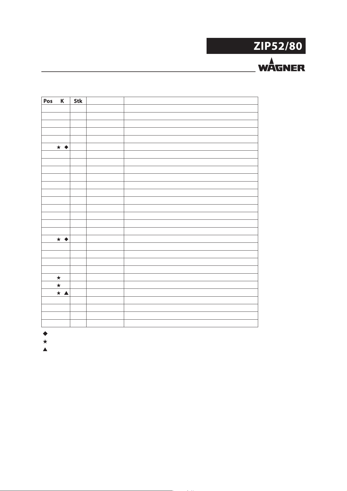
Zip52 metal - universal
Order No. Order No. Order No. Order No. Order No. Description
1 U550.ATRD7 U550.ATSS7 U550.STSS7 U551.303 U551.ATSS7 DDP ZIP
1 1 F184.01C F184.01C F188.03C F184.01C F184.01C Suction manifold
2 1 F185.01C F185.01C F189.03C T6133.00 F185.01C Delivery manifold
3 2 F834.07R F834.07R F834.07R F834.07R F834.07R Outer diaphragm disc
4 2 F978.01 F978.01 F192.03 F978.01 F978.01 Diaphragm cover
5
6 2 G921.06 G921.06 G921.06 G921.06 G921.06 Support diaphragm
7 4 K142.62 K142.62 K142.62 K142.62 K142.62 Screw M6x35
8 4 K183.62 K183.62 -- K183.62 K183.62 Screw M6x30
8 4 -- -- K142.62 -- -- Screw M6x35
9 12 K311.62 K311.62 K311.62 K311.62 K311.62 Nut M6
10 8 9910204 9910204 9910204 9910204 9910204 Nut M6
11 20 9920103 9920103 9920103 9920103 9920103 Washer 6
12 1 K1012.62 K1012.62 K1012.62 K1012.62 K1012.62 Screw
13 2 K1041.62 K1041.62 K1041.62 K1041.62 K1041.62 Rivet
14 12 K1044.62 K1044.62 K1044.62 K1044.62 K1044.62 Screw
15 4 M254.14A M254.14A M811.03B M254.14A M254.14A Plug 1/2
16 1 T6103.00 T6103.00 T6103.00 T6103.00S T6103.00S Motor
17
18 1 Y622.00A Y622.00A Y622.00A Y622.00A Y622.00A Cable lug
19 1 -- -- -- -- -- Coverplate
20 2 -- -- -- -- -- Cover round plate
21 1 B0177.14 B0177.14 B0177.14 B0177.14A B0177.14A Nipples
22
23
24 4 L206.05 L206.05 L206.05 L206.05 L206.05 O-ring
25 1 3201587 3201587 3201587 3201587 3201587 Loctite 577
26 1 9992831 9992831 9992831 9992831 9992831 Loctite 542
2 G921.05 G921.05 G921.05 G921.05 G921.05 Material diaphragm
4 T6105.00C T6105.00 T6105.00 T6105.00 T6105.00 Valve-unit
4 K805.07D K805.03 K805.03 K805.03 K805.03 Ball
4 B0148.07R B0148.03A B0148.03A B0148.03A B0148.03A Ball seat
Wearing part
included in service set
included in product’s o-ring set
47
Page 48

VERSION 12/2012 ORDER NUMBER DOC 2330426
OPERATING MANUAL
11.3 ZIP52 PUMP METAL INDEPENDENT CONNECTIONS
5 Nm; 3.7 lbft
8
2
2
22
23
24
17
13
19
25
21
16
6
14
5
12 Nm; 8.8 lbft
5 Nm; 3.7 lbft
12
18
3
1
1
7
B_04023
5 Nm; 3.7 lbft
4
11
9
10
20
48
Page 49

VERSION 12/2012 ORDER NUMBER DOC 2330426
OPERATING MANUAL
ZIP52 metallic - independent
Order No. Description
1 U550.ATSS8 DDP ZIP52
1 2 F184.01D Suction manifold
2 2 F185.01D Delivery manifold
3 2 F834.07R Outer diaphragm disc
4 2 F978.01 Diaphragm cover
5 2 G921.05 Material diaphragm
6 2 G921.06 Support diaphragm
7 4 K142.62 Screw M6x35
8 4 K183.62 Screw M6x30
9 12 K311.62 Nut M6
10 8 9910204 Nut M6
11 20 9920103 Washer 6
12 1 K1012.62 Self-tapping screw
13 2 K1041.62 Rivet
14 12 K1044.62 Screw
15 -- -- -16 1 T6103.00 Motor
17
18 1 Y622.00A Cable lug
19 1 -- Coverplate
20 2 - - Cover round plate
21 1 B0177.14 Nipples
22
23 4 B0148.03A Ball seat
24 4 L206.05 O-ring
25 1 9992831 Loctite 542
4 T6105.00 Valve-unit
4 K805.03 Ball
Wearing part
included in service set
included in product’s o-ring set
49
Page 50

VERSION 12/2012 ORDER NUMBER DOC 2330426
OPERATING MANUAL
11.4 ZIP52 PUMP CONDUCTIVE ACETAL
4.5 Nm; 3.3 lbft
8
15
27
22
23
24
15
15
17
27
13
19
2
(U55x.xxxx7)
25
21
16
6
3
12
28
18
14
2
(U55x.xxxx1)
26
5
12 Nm; 8.8 lbft
7 Nm; 5.2 lbft
20
4
B_04062
27
1
10
7
4.5 Nm; 3.3 lbft
(U55x.xxxx7)
11
9
1
(U55x.xxxx1)
50
Page 51

VERSION 12/2012 ORDER NUMBER DOC 2330426
OPERATING MANUAL
ZIP52 Conductive Acetal
U552.GHSS1 U552.GHSS7 U553.GTSS1
Order No. Order No. Order No. Description
1 U552.GHSS1 U552.GHSS7 U553.GTSS1 DDP ZIP52
1 1 -- F1017.07G-C -- Suction manifold - universal
1 1 F833.07G-A -- F833.07G-A Suction manifold - left
2 1 -- F1016.07G-C -- Delivery manifold - universal
2 1 F859.07G -- F859.07G Delivery manifold - left
3 2 F834.07D F834.07D F834.07D Extern diaphragm disc
4 2 F831.07G-A F831.07G-A F831.07G-A Diaphragm cover conductive
5
6 2 -- -- G921.06 Support diaphragm
7 4 K128.62 K128.62 K128.62 Screw M6x40
8 4 K1076.62 K1076.62 K1076.62 Screw M6x75
9 20 K311.62 K311.62 K311.62 Nut M6
10 4 9920103 9920103 9920103 Washer 6
11 16 K508.62 K508.62 K508.62 Washer 6x18
12 1 K1012.62 K1012.62 K1012.62 Screw
13 2 K1041.62 K1041.62 K1041.62 Rivet
14 12 K1043.62 K1043.62 K1043.62 Screw
15 4 -- M052.08 -- Plug 1/2"
16 1 T6103.00 T6103.00 T6103.00S Motor
17
18 1 Y622.00A Y622.00A Y622.00A Cable lug
19 1 -- -- -- Coverplate
20 2 -- -- -- Cover round plate
21 1 B0177.14 B0177.14 B0177.14A Nipples
22
23 4 B0148.03A B0148.03A B0148.03A Seat
24
25
26 1 9992831 9992831 9992831 Loctite 542
27 1 -- 3051530 -- PTFE tape
28 1 K558.62 K558.62 K558.62 Washer
2 G921.07B G921.07B G921.05 Diaphragm
4 T6105.00 T6105.00 T6105.00 Valve-unit
4 K805.03 K805.03 K805.03 Ball 3/4"
4 L206.05 L206.05 L206.05 O-ring
2 F856.07D F856.07D F856.07D Ball guide
Wearing part
included in service set
included in product’s o-ring set
51
Page 52

VERSION 12/2012 ORDER NUMBER DOC 2330426
OPERATING MANUAL
11.45 ZIP52 PUMP POLYPROPYLENE UNIVERSAL CONNECTIONS
5 Nm; 3.7 lbft
8
15
22
23
24
15
17
27
13
19
27
25
2
26
21
15
B_04024
27
16
6
14
3
1
7
10
5 Nm; 3.7 lbft
5
12 Nm; 8.8 lbft
7 Nm; 5.2 lbft
4
11
9
20
52
Page 53

VERSION 12/2012 ORDER NUMBER DOC 2330426
OPERATING MANUAL
ZIP52 polypropylene - universal
Order No. Order No. Order No. Description
1 U552.PTSS7 U553.PHSD7 U553.PTSS7 DDP ZIP52
1 1 F1017.07P-C F1017.07P-C F1017.07P-C Suction manifold
2 1 F1016.07P-C F1016.07P-C F1016.07P-C Delivery manifold
3 2 F834.07P F834.07P F834.07P Outer diaphragm disc
4 2 F831.07P-A F831.07P-A F831.07P-A Diaphragm cover
5
6
7 4 K128.62 K128.62 K128.62 Screw M6x40
8 4 K1076.62 K1076.62 K1076.62 Screw M6x75
9 20 K311.62 K311.62 K311.62 Nut M6
10 4 9920103 9920103 9920103 Washer 6
11 16 K508.62 K508.62 K508.62 Washer 6x18
12 -- -- -- -- -13 2 K1041.62 K1041.62 K1041.62 Rivet
14 12 K1043.62 K1043.62 K1043.62 Screw
15 4 M052.08 M052.08 M052.08 Plug 1/2
16 1 T6103.00 T6103.00S T6103.00S Motor
17
18 -- -- -- -- -19 1 -- -- -- Coverplate
20 2 -- -- -- Cover round plate
21 1 B0177.14 B0177.14A B0177.14A Nipples
22
23
24 4 L206.05 L206.05 L206.05 O-ring
25
26 1 9992831 9992831 9992831 Loctite 542
27 1 3051530 3051530 3051530
2 G921.05 G921.07B G921.05 Material diaphragm
2 G921.06 -- G921.06 Support diaphragm
4 T6105.00 T6105.00I T6105.00 Valve-unit
4 K805.03 K805.07D K805.03 Ball
4 B0148.03A B0148.03A B0148.03A Ball seat
2 F856.07P F856.07P F856.07P Ball’s guide insert
PTFE tape
Wearing part
included in service set
included in product’s o-ring set
53
Page 54

VERSION 12/2012 ORDER NUMBER DOC 2330426
OPERATING MANUAL
11.6 ZIP80 PUMP ALUMINUM UNIVERSAL CONNECTIONS
27
25
15
8
2
15
19
12
18
13
26
27
5 Nm; 3.7 lbft
28
21
16
14
5
12 Nm; 8.8 lbft
5.5 Nm; 4.06 lbft
10
3
20
1
15
B_04026
27
15
7
17
22
4
23
24
5 Nm; 3.7 lbft
11
9
54
Page 55
VERSION 12/2012 ORDER NUMBER DOC 2330426
OPERATING MANUAL
Zip80 aluminum - universal
Order No. Description
1 U555.ATSS7 DDP ZIP80
1 1 F186.01C Suction manifold
2 1 F187.01C Delivery manifold
3 2 F838.07R Outer diaphragm disc
4 2 F981.01 Diaphragm cover
5 2 G922.07AB Diaphragm
6-----7 4 K128.62 Screw M6x40
8 4 K142.62 Screw M6x35
9 12 9910208 Nut M8
10 12 K311.62 Nut M6
11 12 9920102 Washer 8
12 1 K1057.62 Screw
13 2 K1041.62 Rivet
14 12 K1053.62 Screw
15 4 M405.24 Plug 3/4
16 1 T6104.00 Motor
17
18 1 Y622.00A Cable lug
19 1 -- Coverplate
20 2 -- Cover round plate
21 1 B0177.14 Nipples
22
23 4 B0149.03A Ball seat
24 4 L208.05 O-ring
25 8 9920103 Washer 6
26 1 K558.62 Washer
27 1 3201587 Loctite 577
28 1 9992831 Loctite 542
4 T6106.00 Valve-unit
4 K803.03 Ball
Wearing part
included in service set
included in product’s o-ring set
55
Page 56

VERSION 12/2012 ORDER NUMBER DOC 2330426
OPERATING MANUAL
11.7 ZIP MOTOR
3.5 Nm; 2.6 lbft
20
19
21
4
21
1
3
3
13
14
17
7
9
2 Nm;
1.5 lbft
11
15
8
1
5
16
21
1
3
21
2 Nm; 1.5 lbft
12
2
B_04027
10
6
18
56
Page 57

VERSION 12/2012 ORDER NUMBER DOC 2330426
OPERATING MANUAL
WARNING
Incorrect maintenance/repair!
Danger to life and equipment damage.
Only a WAGNER service center or a suitably trained person may
carry out repairs and replace parts.
Only repair and replace parts that are listed in the chapter "Spare
Parts Catalogue" and that are assigned to the unit.
Before all work on the unit and in the event of work interruptions:
- Disconnect the control unit from the mains.
- Relieve the pressure from the spray gun and unit.
- Secure the spray gun against actuation.
Observe the operating and service instructions when carrying
out all work.
ZIP motor
Order No. Order No. Order No. Description
1 T6103.00 T6103.00S T6104.00 Motor
1 2 B0146.04 B0146.04 B0146.04 Feeler pin
2 2 B0147.71 B0147.71 B0151.71 Inner diaphragm disc
3 1 B0150.03 B0150.03S B0150.03 Shaft
4 1 F194.91 F194.91 F194.91 Cover (pressure side)
5
6 1 F830.07 F830.07 F830.07 Cover (exhaust side)
7 1 T6103.00A T6103.00A T6104.00A Motor block with safety valve
8
9
10 1 H618.07 H618.07 H618.07 Noise reduction
11 4 K1038.62 K1038.62 K1038.62 Screw
12 6 K1039.62 K1039.62 K1039.62 Screw
13 2 L470.06 L470.06 L470.06 Lip seal
14 2 L471.06 L471.06 L471.06 Lip seal
15 1 P4003.00 P4003.00 P4003.00 Reversing valve (*)
16 1 See pos. 7. See pos. 7. See pos. 7. Safety valve (**)
17 1 Z546.C0 Z546.C0 Z546.C0B Side label
18 4 K1040.62 K1040.62 K1040.62 Screw
19 4 3155401 3155401 3155401 Contact washer
20 4 K311.62 K311.62 K311.62 Self-locking nut M6
21 Z125.00 Z125.00 Z125.00 High-performance grease
(*) Includes pos. 8 and 9.
Not available separately
(**)
2 F829.07 F829.07 F829.07 Shaft guide bushing
1 G925.06 G925.06 G925.06 Reversing valve gasket
1 G7020.06 G7020.06 G7020.06 Pressure cover gasket
Wearing part
included in pump's service set
57
Page 58

VERSION 12/2012 ORDER NUMBER DOC 2330426
OPERATING MANUAL
11.8 SERVICE SETS
Pump No. Diaphragm Valve seat Valve ball Service set O-ring set Air valve set
U550.ATRD7 PTFE PPS Acetal (POM) T9080.00A T9077.00 P4003.00
U550.ATSS7 PTFE Stainless steel Stainless steel T9080.00 T9077.00 P4003.00
U550.ATSS8 PTFE Stainless steel Stainless steel T9080.00 T9077.00 P4003.00
U550.STSS7 PTFE Stainless steel Stainless steel T9080.00 T9077.00 P4003.00
U551.ATSS7 PTFE Stainless steel Stainless steel T9080.00 T9077.00 P4003.00
U551.303 PTFE Stainless steel Stainless steel T9080.00 T9077.00 P4003.00
U552.GHSS1 UHMWPE Stainless steel Stainless steel T9080.00B T9077.00 P4003.00
U552.GHSS7 UHMWPE Stainless steel Stainless steel T9080.00B T9077.00 P4003.00
U552.PTSS7 PTFE Stainless steel Stainless steel T9080.00 T9077.00 P4003.00
U553.GTSS1 PTFE Stainless steel Stainless steel T9080.00B T9077.00 P4003.00
U553.PHSD7 UHMWPE Stainless steel Acetal (POM) T9080.00G T9077.00 P4003.00
U553.PTSS7 PTFE Stainless steel Stainless steel T9080.00 T9077.00 P4003.00
U555.ATSS7 PTFE Stainless steel Stainless steel T9085.00 T9084.00 P4003.00
Service set consists of: see parts list
O-Ring set consists of:
4 O-rings for the valve units (material check valves)
Air valve set consists of:
1 Reversing valve
1 Reversing valve seals
1 Pressure cover seals
58
Page 59

VERSION 12/2012 ORDER NUMBER DOC 2330426
OPERATING MANUAL
12 GUARANTEE AND CONFORMITY DECLARATIONS
12.1 IMPORTANT NOTES REGARDING PRODUCT LIABILITY
As a result of an EC regulation e ective from January 1, 1990, the manufacturer shall only
be liable for his product if all parts originate from him or are approved by him, and if the
devices are properly mounted, operated and maintained.
The manufacturer will not be held liable or will only be held partially liable if third-party
accessories or spare parts have been used.
With genuine WAGNER accessories and spare parts, you have the guarantee that all safety
regulations are complied with.
12.2 GUARANTEE CLAIM
Full warranty is provided for this device:
We will at our discretion repair or replace free of charge all parts which within 36 months
in single-shift, 18 months in double-shift or 9 months in triple-shift operation from date of
receipt by the purchaser are found to be wholly or substantially unusable due to causes
prior to the sale, in particular faulty design, defective materials or poor workmanship.
The type of warranty provided is such that the device or individual components of the
device are either replaced or repaired as we see t. The resulting costs, in particular
shipping charges, road tolls, labour and material costs will be borne by us except where
these costs are increased due to the subsequent shipment of the unit to a location other
than the address of the purchaser.
We do not provide warranty for damage that has been caused or contributed to for the
following reasons:
Unsuitable or improper use, faulty installation or commissioning by the purchaser or a
third party, normal wear, negligent handling, defective maintenance, unsuitable coating
products, substitute materials and the action of chemical, electrochemical or electrical
agents, except when the damage is attributable to us.
Abrasive coating products such as red lead, emulsions, glazes, liquid abrasives, zinc
dust paints and so forth reduce the service life of valves, packaging, spray guns, nozzles,
cylinders, pistons etc. Wear and tear due to such causes are not covered by this guarantee.
Components that have not been manufactured by WAGNER are subject to the original
warranty of the manufacturer.
Replacement of a component does not extend the period of warranty of the device.
The unit should be inspected immediately upon receipt. To avoid losing the warranty, we
or the supplier company are to be informed in writing about obvious faults within 14 days
upon receipt of the device.
We reserve the right to have the warranty compliance met by a contracting company.
The services provided by this warranty are dependent on evidence being provided in the
form of an invoice or delivery note. If the examination discovers that no warranty claim
exists, the costs of repairs are charged to the purchaser.
It is clearly stipulated that this warranty claim does not represent any constraint on statutory
regulations or regulations agreed to contractually in our general terms and conditions.
J. Wagner AG
59
Page 60

VERSION 12/2012 ORDER NUMBER DOC 2330426
OPERATING MANUAL
12.3 CE DECLARATION OF CONFORMITY
Metallic versions (aluminum and stainless steel) and conductive Acetal
Herewith we declare that the supplied version of the Pneumatic Double Diaphragm Pumps
with ordner no.
U550.ATRD7 U551.ATSS7 U555.ATSS7
U550.ATSS7 U551.303
U550.ATSS8 U553.GTSS1
U550.STSS7
U552.GHSS1
U552.GHSS7
complies with the following guidelines:
2006/42/EC 94/9/EC Atex directive
Applied standards, in particular:
DIN EN ISO 12100: 2011 DIN EN 809: 2012 DIN EN ISO 4413: 2011
DIN EN ISO 4414: 2011 DIN EN 12621: 2011 DIN EN 1127-1: 2011
DIN EN ISO 13463-1: 2009 DIN EN ISO 13732-1: 2008 DIN EN 14462: 2010
Applied national technical standards and speci cations, in particular:
BGR 500 part 2 chapter 2.29 and chapter 2.36 TRBS 2153
Identi cation:
II 2G IIB T4 +4°C Tamb +40°C
CE Certi cate of Conformity
The CE certi cate of conformity is enclosed with this product. If needed, further copies
can be ordered through your WAGNER dealer by specifying the product name and serial
number.
Order number: 2334618
60
Page 61

VERSION 12/2012 ORDER NUMBER DOC 2330426
OPERATING MANUAL
Non-metallic versions (Non-conductive polypropylene)
Herewith we declare that the supplied version of the Pneumatic Double Diaphragm Pumps
with ordner no.
U552.PTSS7 U553.PHSD7
U553.PTSS7
complies with the following guidelines:
2006/42/EC
Applied standards, in particular:
DIN EN ISO 12100: 2011 DIN EN 809: 2012 DIN EN ISO 4413: 2011
DIN EN ISO 4414: 2011 DIN EN 12621: 2011 DIN EN ISO 13732-1: 2008
DIN EN 14462: 2010
Applied national technical standards and speci cations, in particular:
BGR 500 part 2 chapter 2.29 and chapter 2.36 TRBS 2153
Identi cation:
CE Certi cate of Conformity
The CE certi cate of conformity is enclosed with this product. If needed, further copies
can be ordered through your WAGNER dealer by specifying the product name and serial
number.
Order number: 2334619
61
Page 62

VERSION 12/2012 ORDER NUMBER DOC 2330426
OPERATING MANUAL
Germany
J. WAGNER GmbH
Otto-Lilienthal-Str. 18
Postfach 1120
D- 88677 Markdorf
Telephone: +49 7544 5050
Telefax: +49 7544 505200
E-Mail: service.standard@wagner-group.com
Belgium
WSB Finishing Equipment
Veilinglaan 56/58
B- 1861 Wolvertem
Telephone: +32 (0)2 269 4675
Telefax: +32 (0)2 269 7845
E-Mail: info@wsb-wagner.be / HP www.wsb-wagner.eu
United Kingdom
WAGNER Spraytech (UK) Ltd.
Haslemere Way
Tramway Industrial Estate
GB- Banbury, OXON OX16 8TY
Telephone: +44 (0)1295 265 353
Telefax: +44 (0)1295 269861
E-Mail: enquiries@wagnerspraytech.co.uk
Netherlands
WSB Finishing Equipment B.V.
De Heldinnenlaan 200
NL- 3543 MB Utrecht
Switzerland
J. WAGNER AG
Industriestrasse 22
Postfach 663
CH- 9450 Altstätten
Telephone: +41 (0)71 757 2211
Telefax: +41 (0)71 757 2222
E-Mail: rep-ch@wagner-group.ch
Denmark
WAGNER Industrial Solution Scandinavia
Viborgvej 100, Skærgær
DK- 8600 Silkeborg
Telephone: +45 70 200 245
Telefax: +45 86 856 027
E-Mail info@wagner-industri.com
France
J. WAGNER France S.A.R.L.
Parc de Gutenberg - Bâtiment F8
8, Voie la Cardon
F- 91127 Palaiseau-Cedex
Telephone: +33 1 825 011 111
Telefax: +33 1691 946 55
E-Mail: division.solutionsindustrielles@wagner-france.fr
Italy
WAGNER COLORA S.r.l
Via Fermi, 3
I- 20875 Burago di M
olgora (MB)
Telephone: +31 (0) 30 241 4155
Telefax: +31 (0) 30 241 1787
E-Mail: info@wsb-wagner.nl / HP www.wsb-wagner.eu
Japan
WAGNER Spraytech Ltd.
2-35, Shinden Nishimachi
J- Daito Shi, Osaka, 574-0057
Telephone: +81 (0) 720 874 3561
Telefax: +81/ (0) 720 874 3426
E-Mail: marketing@wagner-japan.co.jp
Sweden
WAGNER Industrial Solutions Scandinavia
Skolgatan 61
SE- 568 31 Skillingaryd
Telephone: +46 (0) 370 798 30
Telefax: +46 (0) 370 798 48
E-Mail: info@wagner-industri.com
Czechoslovakia
WAGNER s.r.o.
Nedasovská Str. 345
15521 Praha 5 - Zlicin
Telephone: +42 (0) 2 579 50 412
Telefax: +42 (0)2 579 51 052
E-Mail: info@wagner.cz
Telephone: +39 039 625021
Telefax: +39 039 6851800
E-Mail: info@wagnercolora.com
Austria
J. WAGNER GmbH
Otto-Lilienthal-Str. 18
Postfach 1120
D- 88677 Markdorf
Telephone: +49 (0) 7544 5050
Telefax: +49 (0) 7544 505200
E-Mail: service.standard@wagner-group.com
Spain
WAGNER Spraytech Iberica S.A.
Ctra. N- 340, Km. 1245,4
E- 08750 Molins de Rei (Barcelona)
Telephone: +34 (0) 93 680 0028
Telefax: +34 (0) 93 668 0156
E-Mail: info@wagnerspain.com
USA
WAGNER Systems Inc.
300 Airport Road, unit 1
Elgin, IL 60123 USA
Telephone: +1 630 503 2400
Telefax: +1 630 503 2377
E-Mail: info@wagnersystemsinc.com
62
Page 63

Page 64

Order No. 2330426
People‘s Republic of China
Tel. +86 / (0)21 6652 / 1858
Fax +86 / (0)21 6630 / 8085
Germany
Tel.
Fax
E-mail
 Loading...