

Page 1
®
GB
Owner’s Manual
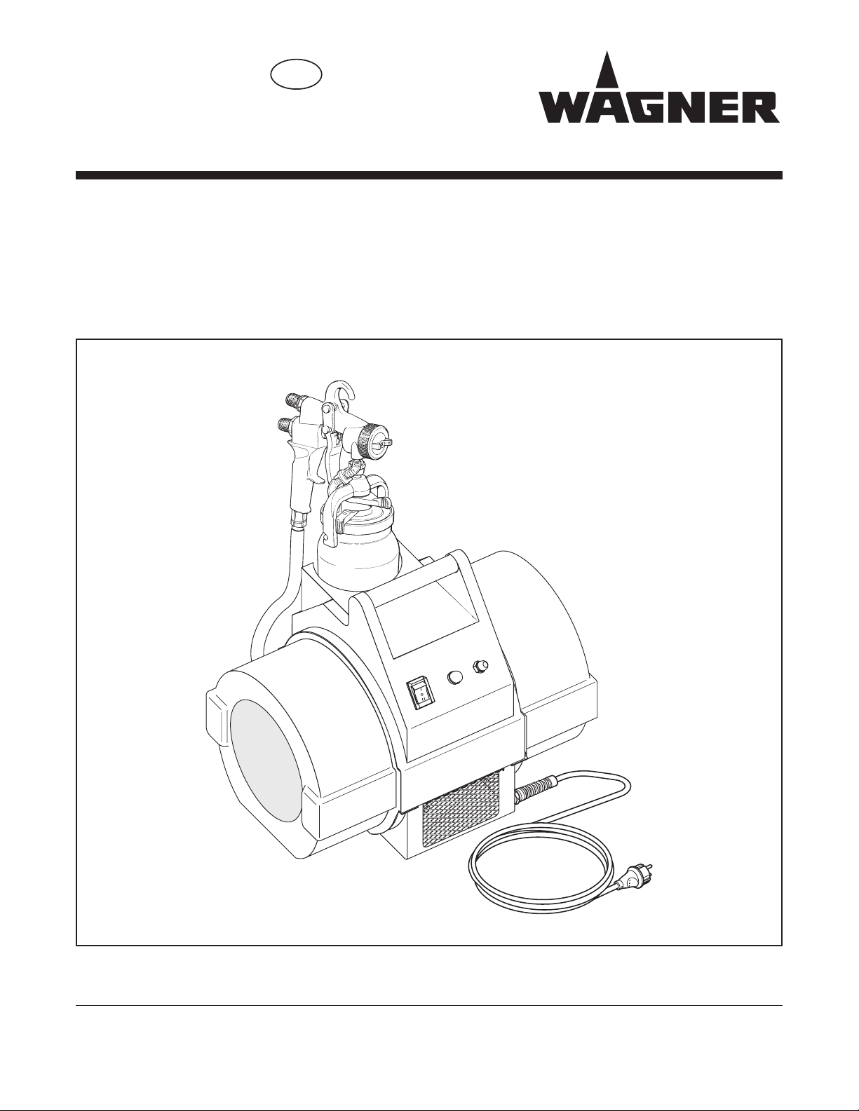
FineCoat Coating System
Model 0524016
FineCoat 9900
Edition 10 / 2010 0524 834B
Page 2

GB
Contents
Attention
i
Page
Safety regulations for FineCoat spraying ............................... 3
Introduction to spraying using the FineCoat procedure ....... 4
Description of functions ........................................................... 4
Applications ...............................................................................4
What kind of spraying materials can be applied? ..................4
Technical data............................................................................ 4
System diagram ......................................................................... 4
Preparing the coating material ................................................. 5
Table of viscosities and nozzle sets ............................................ 5
Starting operation ......................................................................5
Setting the FineCoat spray gun ............................................5/6
Spray pattern selection ................................................................ 5
Setting the required spray pattern ............................................... 5
Setting the spray jet width ...........................................................6
Setting the amount of material..................................................... 6
Setting the amount of air .............................................................6
Setting the ascending feed pipe .................................................. 6
Spraying technique ................................................................... 7
Breaks in work ........................................................................... 7
Finishing work and cleaning the unit ................................... 7/8
Changing the nozzle .................................................................... 8
Spray gun accessories and spare parts.................................. 9
Nozzle sets .................................................................................. 9
Table of nozzle sets..................................................................... 9
Hose whip .................................................................................... 9
Valve plate set ............................................................................. 9
Service set ................................................................................... 9
Page
Turbo-blower maintenance .......................................................9
Changing the air lter ..................................................................9
Carbon brushes ........................................................................... 9
Special accessories ................................................................10
RN 30 Extension tip ................................................................... 10
WSL 50 Spray lance .................................................................. 10
WSL 60 Spray lance .................................................................. 10
1.9 L Remote pressure tank ...................................................... 10
Power Cart................................................................................. 10
Troubleshooting ...................................................................... 11
Spare parts list, FineCoat spray gun ......................................... 12
Spare parts list, turbo-blower FineCoat 9900 ............................ 14
Spare parts list, air hose FineCoat 9900 ................................... 16
Connection Diagram ...............................................................17
WAGNER-Service companies ................................................18
Important notes on product liability ...................................... 19
3+2 years guarantee for professional nishing ................... 19
CE Declaration of conformity ................................................. 20
Safety Regulations for FineCoat Spraying
This manual contains information that must be read and understood
before using the equipment. When you come to an area that has one of
the following symbols, pay particular attention and make certain to heed
the safeguard.
This symbol indicates a potential hazard that may cause
serious injury or loss of life. Important safety
information will follow.
This symbol indicates a potential hazard to you or to the
equipment. Important information that tells how to
prevent damage to the equipment or how to avoid
causes of minor injuries will follow.
A hazard symbol such as this one refers to a specific,
task-related risk. Be sure to heed the safeguard.
Notes give important information which should be given
special attention.
2
HAZARD: GENERAL
This product can cause severe injury or property
damage.
PREVENTION:
• Read all instructions and safety precautions before
operating equipment.
• Follow all appropriate local, state, and national codes
governing ventilation, re prevention, and operation.
• Use only manufacturer authorized parts. User
assumes all risks and liabilities when using parts that
do not meet the minimum specications and safety
devices of the pump manufacturer.
• Before each use, check all hoses for cuts, leaks,
abrasion or bulging of cover. Check for damage or
movement of couplings. Immediately replace the hose
if any of these conditions exist. Never repair a hose.
Replace it with an identical replacement hose.
• NEVER aim the gun at any part of the body.
• Wear clothing to keep paint off skin and hair.
• Do not spray outdoors on windy days.
• Never leave this equipment unattended. Keep away
from children or anyone not familiar with the operation
of HVLP equipment.
Page 3
GB
HAZARD: EXPLOSION OR FIRE
PE
i
PE
Solvent and paint fumes can explode or ignite. Severe
injury and/or property damage can occur.
PREVENTION:
• Provide extensive exhaust and fresh air introduction
to keep the air within the spray area free from
accumulation of ammable vapors.
• Avoid all ignition sources such as static electricity
sparks, electrical appliances, ames, pilot lights, hot
objects, and sparks from connecting and disconnecting
power cords or working light switches.
• Plastic can cause static sparks. Never hang plastic
to enclose spray area. Do not use plastic drop cloths
when spraying ammable materials.
• Do not smoke in spray area.
• Fire extinguisher must be present and in good working
order.
• Power cord must be connected to a grounded circuit
(electric units only).
• Follow material and solvent manufacturer’s warnings
and instructions. Be familiar with the coating material’s
MSDS sheet and technical information to ensure safe
use.
• Use extreme caution when using materials with a
ashpoint below 70° F (21° C). Flashpoint is the
temperature that a uid can produce enough vapors to
ignite.
HAZARD: SKIN BURN INJURY
Heated parts can cause severe skin burn injury.
PREVENTION:
• Quick disconnect ttings on the hose and spray gun
become hot during use. Avoid skin contact with quick
disconnect ttings when they are hot. Allow quick
disconnect ttings to cool before disconnecting the
spray gun from the hose.
Earthing Instructions
Electric models must be earthed. In the event of an
electrical short circuit, earthing reduces the risk of electric
shock by providing an escape wire for the electric current.
This product is equipped with a cord having an earthing
wire with an appropriate earthing plug. The plug must be
plugged into an outlet that is properly installed and earthed
in accordance with all local codes and ordinances.
DANGER — Improper installation of the earthing plug
can result in a risk of electric shock. If repair or
replacement of the cord or plug is necessary, do not
connect the green earthing wire to either blade
terminal. The wire with insulation having a green outer
surface with or without yellow stripes is the earthing
wire and must be connected to the earthing pin.
Check with a qualied electrician or serviceman if the earthing
instructions are not completely understood, or if you are in doubt as to
whether the product is properly earthed. Do not modify the plug provided.
If the plug will not t the outlet, have the proper outlet installed by a
qualied electrician.
Caution – The power cord for this equipment acts as an
emergency stop/emergency switching off device. The
power cord must be placed near an easily accessible,
unobstructed socket-outlet.
HAZARD: EXPLOSION HAZARD DUE TO
INCOMPATIBLE MATERIALS
Will cause severe injury or property damage.
PREVENTION:
• Do not use materials containing bleach or chlorine.
• Do not use halogenated hydrocarbon solvents such
as methylene chloride and 1,1,1 - trichloroethane.
They are not compatible with aluminum and may
cause an explosion. If you are unsure of a material’s
compatibility with aluminum, contact your coating’s
supplier.
HAZARD: HAZARDOUS VAPORS
Paints, solvents, insecticides, and other materials
can be harmful if inhaled or come in contact with
body. Vapors can cause severe nausea, fainting, or
poisoning.
PREVENTION:
• Use a respirator or mask if vapors can be inhaled.
Read all instructions supplied with the mask to be sure
it will provide the necessary protection.
• Wear protective eyewear.
• Wear protective clothing as required by coating
manufacturer.
Work or repairs at the electrical equipment:
These may only be carried out by a skilled electrician. No liability is
assumed for incorrect installation.
Power cord replacement must be performed by the manufacturer, its
service agent, or a similarly qualied person.
Operating Temperature
This equipment will operate correctly in its intended ambient, at a
minimum between +10°C and +40°C.
Relative Humidity
The equipment will operate correctly within an environment at 50% RH,
+40°C. Higher RH may be allowed at lower temperatures.
Measures shall be taken by the Purchaser to avoid the harmful effects of
occasional condensation.
Altitude
This equipment will operate correctly up to 3000 m above mean sea level.
Transportation and Storage
This equipment will withstand, or has been protected against,
transportation and storage temperatures of -25°C to +55°C and for short
periods up to +70°C.
It has been packaged to prevent damage from the effects of normal
humidity, vibration and shock.
A list of the materials used in the construction of the
equipment will be made available on request to validate
compatibility with the coating materials to be used.
3
Page 4
GB
Introduction to spraying using the
1
14
10
13
2
3
4
5
6
7
8
9
12 11
FineCoat procedure
FineCoat is a low pressure spraying technique which operates
with a high volume of air at low air pressure.
The essential advantage of this system is the reduced formation
of spray mist. The material required to cover a given surface is
thus reduced to a minimum.
The FineCoat system is particularly suitable for repairing and
renovating.
Compared to conventional coating applications, an economical
and superior surface finish is achieved with an environmentally
friendly application.
Description of Functions
The “FineCoat 9900” spray application system consists of a
turbo-blower which supplies a FineCoat paint spray gun with
atomizing air via an air hose.
In the spray gun, part of the atomizing air is used to increase the
pressure in the paint container. This pressure is used to convey
coating material through the ascending feed pipe to the tip where
it is mixed with the rest of the atomized air.
Applications
• Renovation and repair work
• Interior wall decoration
What kind of spraying materials can be
applied?
• Water-soluble and solvent-containing coating materials
• Wood preservatives
• Multi-color effect materials
• Multi-color paint
• Texture and effect paints
Technical Data
FineCoat 9900
Voltage : 230V~, 50/60 Hz
Power consumption P1 : 1500 W
Max. current comsumption : 7.5 A
Max. air ram pressure : 0.68 bar
Rpm : 21 000 rpm
Weight (turbo-blower,
air hose and spray gun) : 15 kg
Mains cable : 3 m
Container capacity : 1 liter
Air hose : 7.5 m
Nozzle set (standard) : No. 4 (1.8 mm)
Max. permissible
coating temperature : 43ºC
Typical coating flow rate : 0.35 l/min
Max. noise level
turbo-blower : 75 dB (A) *
paint spray gun : 80 dB (A) **
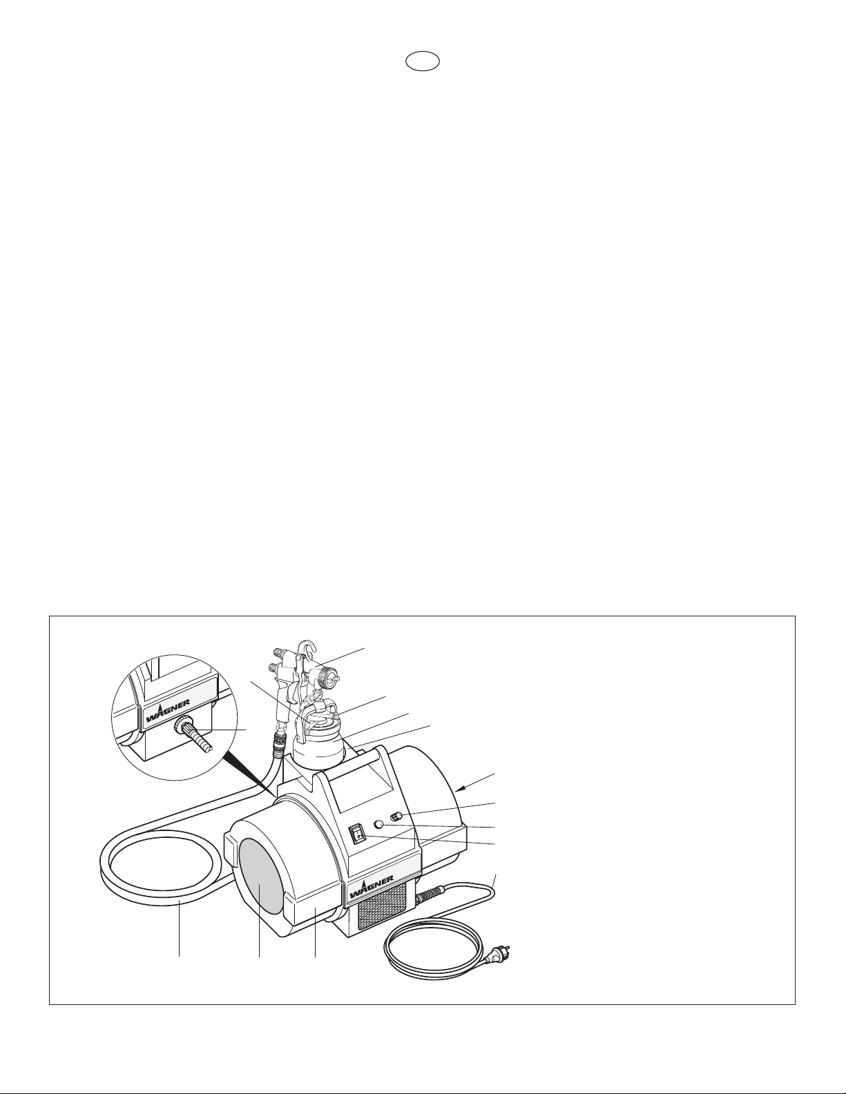
System Diagram
* Measuring location: 1 m in distance from the unit 1.60 m
above the oor, reverberant oor.
** Measuring location: 2.5 m distance from the unit 1.60 m
above the oor.
1 FineCoat paint spray gun
2 Closing lever for paint container
3 Paint container (contents: 1 liter)
4 Spray gun holder
5 Air lter
6 Fine wire fuse
7 Indicator lamp for air lter
contamination
8 ON/OFF switch
9 Mains cable
10 Turbo-blower
11 Motor air lter
12 Air hose
13 Air hose connection
14 Rotating lever for ascending
feed pipe
4
Page 5
GB
Preparing the coating material
Coating material
Solvent-based
lacquer paints
Water-soluble
lacquer paints
Wood preservatives
(scumble, mordants, etc).
Multi-color effect materials,
multi-color paint
Texture and effect
paints
Viscosity DIN-s
(4 mm DIN cup)
15 - 45
observe manufacturer’s
instructions
undiluted
observe manufacturer’s
instructions
observe manufacturer’s
instructions
3 - 4
4 - 5
2 - 3
6 - 7
5 - 6
Nozzle set
No.
ABC
2
1
3
Observe the manufacturer’s instructions for the use of the coating
material on the paint tin or on the technical instruction sheet.
Coating material purity:
An absolute pre-condition for the trouble-free operation of the
ne-spray system is that the coating material is uncontaminated.
If you have doubts as to the purity of the coating material, we
recommend that you rst lter it through a ne sieve.
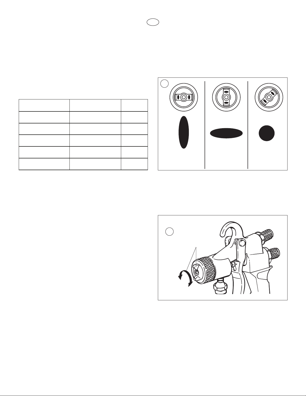
Table of viscosities and nozzle sets
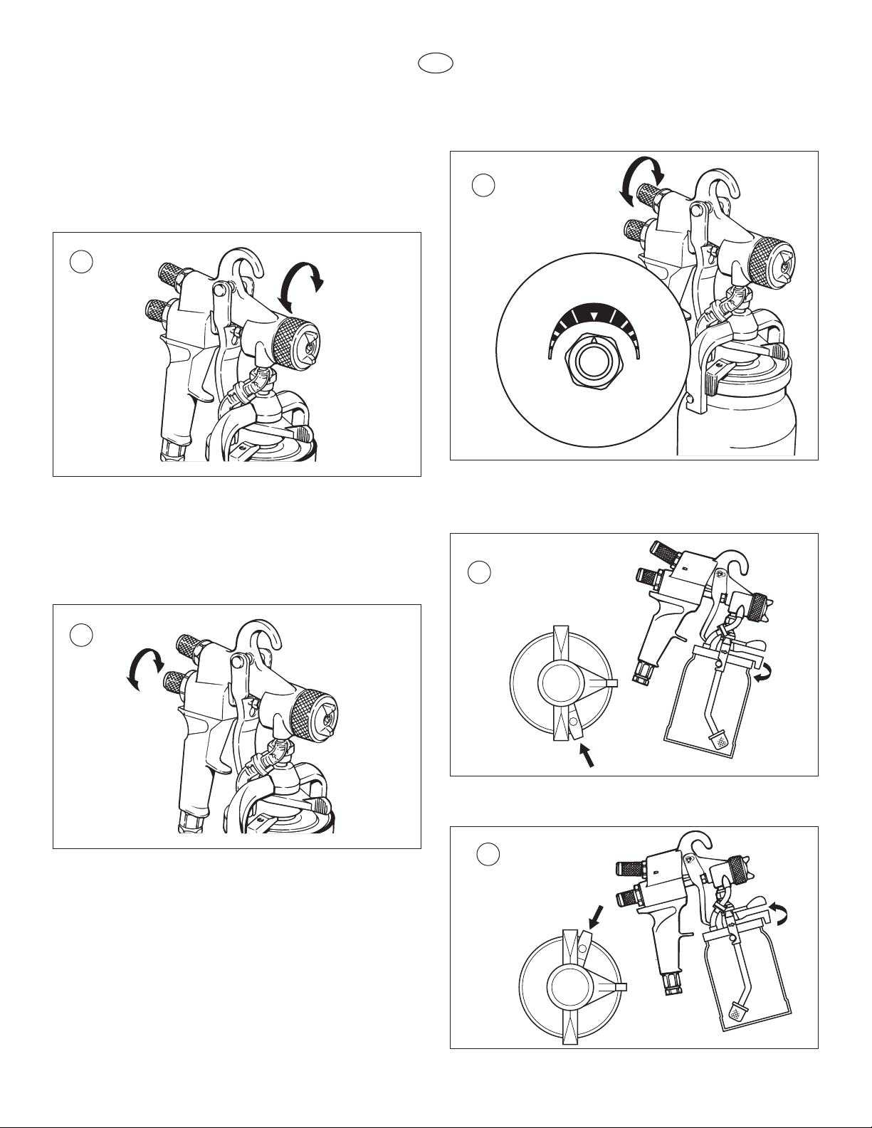
Setting the FineCoat Spray Gun
Spray pattern selection (g. 2)
A = vertical at jet for horizontal surfaces
B = horizontal at jet for vertical surfaces
C = Round jet for corners and edges and places difcult to
access.
Starting operation
Before connecting to the mains supply make sure that the mains
voltage corresponds to the operating voltage on the rating plate.
The unit must be connected with a properly earthed shockproof
socket.
1. Screw air hose end (anti-kink spring) onto the turboblower.
Couple air hose to the paint spray gun.
2. Open closing lever on the paint container, remove paint
container.
3. Fill paint container with coating material.
4. Check that the paint container seal is clean and is seated
correctly.
5. Clip the container onto the spray gun and secure with the
closing lever.
6. Switch the turbo-blower on.
7. Point the paint spray gun at the object to be sprayed.
8. Determine the settings for the spray pattern, spray
jet width, amount of material, amount of air and
ascending feed pipe settings, see g. 2 - 8 and the
description page 5/6.
9. Operate trigger on the paint spray gun.
5
Setting the required spray pattern (g. 3)
Turn the air cap (1) to the required spray pattern position.
Attention:
Never pull trigger while adjusting the air cap settings.
Page 6
GB
Setting the spray jet width (fig. 4)
4
5
Maximum
Minimum Minimum
6
7
8
Adjusting ring
Turn to the right = wider spray jet
Turn to the left = narrower spray jet
Note:
The adjusting ring does not fasten the air cap!
Setting the amount of material (fig. 5)
Set the amount of material by turning the material adjustment
knob.
Turn to the left = more material
Turn to the right = less material
Setting the amount of air (fig. 6)
The correct setting for the amount of air is decisive for the
atomization and formation of paint mist.
Setting the ascending feed pipe
Spraying object lying on oor (g. 7)
Turn rotating lever clockwise as far as it will go.
Spraying object over head (g. 8)
Turn rotating lever anti-clockwise as far as it will go.
6
Page 7

GB
Spraying technique
3 - 20 cm
9
10
11
Hold the paint spray gun upright and maintain a constant
distance of about 3 - 20 cm to the object being sprayed.
Move the paint spray gun evenly either from side to side or up
and down. If the gun is moved evenly, it will produce an even
surface nish. No runs will occur if the speed is correct.
Always start spraying away from the object and avoid stopping
spraying whilst still on the object.
Note: If the round jet setting is used, the distance may be
increased according to the size of the object being sprayed.
• In case of excessive paint mist formation, adjust
the air and material ow respectively and alter the
distance from the object.
Right
Wrong
Excessive paint mist formation, uneven surface nish.
Breaks in work
• Turn the material regulating knob to the right as far as it
will go (g. 11).
This will secure the paint spray gun against unintentional
operation.
• Switch the unit off.
Finishing work and cleaning the unit
1. Switch the unit off.
2. Hold the paint spray gun in the original container. Press
the trigger to release the pressure in the spray gun
container.
3. Undo the paint container closing lever and remove the
container.
4. Empty the remaining coating material into the original
container.
5. Fill the spray gun container with solvent or water and t
onto the spray gun.
Only use solvents with a ash point above 21 °C.
6. Shake the paint spray gun well.
7. Switch the unit on and spray the solvent or water into an
open container.
Caution! Never spray into a container with only a
small opening (bunghole)! See safety regulations.
8. Repeat this procedure until the solvent or water coming
out of the tip is clear.
Then empty the paint container completely.
Caution! Never leave solvents in the spray gun
container; this may cause pressure to build up in the
container.
Always keep the paint container seal clean of left over
coating material and check regularly for signs of damage.
7
Page 8

GB
9. Switch the unit off.
12
13
2
3
4
1
14
5
15
16
10. Clean the outer surfaces of the paint container and paint
spray gun with a cloth soaked in solvent or water.
Note: Do not leave the FineCoat spray gun immersed
in solvent for extended periods! (The seals and air pipe
on non-return valve may swell, preventing them from
functioning properly.)
11. Unscrew adjusting ring, remove air cap and spring plate
(g. 13). Unscrew nozzle. Clean air cap, tip and needle
with brush and solvent or water.
Note: Never use sharp metal objects to clean the nozzles
or air channels of the FineCoat spray gun.
12. Apply a ne coat of silicone-free oil to the marked areas
(g 12).
3. Remove the needle (g. 15,5).
13. If the paint spray gun is not used for any length of time, it
should be cleaned and protected by applying a ne coat of
silicone-free oil..
Changing the nozzle
Note: Make sure that the air cap, the tip and the needle have
identical markings.
1. Remove the adjusting ring, the air cap and the spring
plate (g. 13).
4. Remove the tip with the enclosed special socket wrench
(g. 16).
2. Fig. 14 – Loosen the needle seal with the open-end
wrench (g. 14,1). Remove the material adjusting knob
(g. 14,2) and the pressure spring (g. 14,3). Open trigger
of the spray gun to facilitate needle removal (g. 14,4).
Reassemble with the new nozzle set in reverse order.
Attention: The needle seal screw connection must be
readjusted after reassembly.
8
Page 9

GB
Spray gun accessories and spare parts
Air cap
Tip
Needle
4
4
4
17
2
1
3
18
Nozzle sets:
The spray nozzle set consists of an air cap, a tip and a needle
(g. 17).
Table of nozzle sets
Set (complete)
Marking Part No. Tip size
2 0276 254 Ø 0,8 mm
3 0276 227 Ø 1,3 mm
4 0276 228 Ø 1,8 mm (Standard)
5 0276 229 Ø 2,2 mm
6 0276 245 Ø 2,5 mm
7 0524 211 Ø 2,7 mm
8 0261 021 Ø 3,0 mm
9 0261 022 Ø 4,0 mm
Turbo-blower maintenance
1. Changing air lter and motor air lter
The indicator lamp (1) shows that the air lter (2) and the
motor air lter (3) need cleaning or exchanging.
Turn off turbo-blower.
Remove the air lter (2) and motor air lter (3) from the
turbo-blower.
Depending on how dirty the lters are, either clean by
blowing through compressed air or exchange the lters.
Care must be taken when retting the air lter (2) that the
green side is on the inside.
Hose whip 152 cm long
Part No. 0524 405
Valve plate set for non-return valve
10 pcs. Part No. 0277 919
Service-Set
consisting of seal item 5, page 12, seal item 8, seal item 17,
needle seal item 27, air pipe item 32, non-return valve item 34,
air pipe item 35, paint container seal item 49.
Part No. 0295 981
Air lter and motor air lter
Part No. 0279 938
2. Carbon brushes
The carbon brushes of the turbo-blower must be replaced
once per year or every 500 hours of operation.
Please contact your WAGNER service center.
9
Page 10

GB
Special accessories
19
20
21
22
RN 30 Extension Tip (g. 19)
for ribbed radiators, length 30cm.
Part No. 0261 020
WSL 50 Spray lance (g. 20)
Area of application
Removating and repair work
For ceilings and walls
Material supply by means of a commercially available pressure
tank.
Part No. 0261 023
WSL 60 Spray lance (fig. 21)
When coating materials can be used?
Coating materials which, due to their properties, cannot be used
with a paint spray gun, e.g., liquid wood chip, multi-color effect
coating, ornamental plaster, texture and spray ller, etc.
Part No. 0261 024
Power Cart
Part No. 0524 001
1.9 L Remote Pressure Tank (fig. 22)
Part No. 0524 230
10
Page 11

GB
Troubleshooting
Problem
A. The unit will not start.
B. No coating material ow from
the tip.
C. Tip drips.
D. Spray pattern sickle-shaped.
E. Spray jet utters.
F. Leaks around the needle (3)*.
Cause
1. No mains voltage.
2. Carbon brushes in motor worn.
3. Fine-wire fuse defect.
4. ON/OFF switch defect.
5. Motor defect.
1. Tip clogged.
2. Non-return valve (34)* clogged.
3. Paint container seal damaged.
4. Filter (48)* clogged.
5. Paint container empty.
6. Adjusting ring (30)* open too far.
7. Material adjusting knob (1)* closed.
1. Worn tip.
2. Contamination in tip.
3. Material adjusting knob open too far.
4. Needle seal screw connection (20)* overtightened.
1. Air cap holes plugged.
1. Coating material in paint container is
running out.
2. Filter clogged.
1. Needle seal screw connection (20)* loose.
2. Needle seal (26)* worn.
Solution
1. Check.
2. Replace.
3. Have checked and replaced by a specialist
electrician.
4. Have replaced by a specialist electrician.
5. Call WAGNER service.
1. Clean tip.
2. Unscrew non-return valve and clean or exchange
valve plate. Pay attention to the direction of the
arrow during assembly.
3. Replace.
4. Clean or replace.
5. Rell.
6. Adjust.
7. Adjust.
1. Replace.
2. Clean.
3. Adjust material adjusting knob accordingly (see page
6).
4. Adjust.
1. Clean.
1. Rell coating material.
2. Clean or replace.
1. Tighten screw connection for needle seal (20)*
loosely with open-end wrench.
2. Tighten or replace the needle seal (26).
*see page 12-13
11
Page 12

GB
34
33
1
2
3
4
5
6
7
8
9
10
11
12
13
14
15
28
29
23
22
21
20
16
19
26
17
25
30
32
50
49
48
47
45
44
43
46
42
41
40
39
38
3
3
35
18
24
52
27
Spare Parts List, FineCoat spray gun
12
Page 13

GB
Item Part No. Description
Item Part No. Description
0277 035 FineCoat paint spray gun
1 0277 502 Material adjusting knob
2 0295 575 Pressure spring
3 0276 228 Nozzle set no. 4 (consists of air cap, tip
and needle)
4 0277 510 Housing
5 0275 501 Seal
6 0275 578 Pressure spring
7 0277 536 Tappet
8 0277 486 Seal
9 0277 489 Retaining ring
10 9811 119 Hexagon nut
11 9805 205 Screw
12 0277 491 Knob
13 9894 242 Spring washer
14 0277 498 Valve housing
15 0277 493 Valve
16 0277 488 Seal
17 0277 506 Double socket
18 0277 185 Housing
19 0277 515 Retaining ring
20 0277 508 Screw connection
21 0277 445 Handle
22 0277 230 Pipe
23 0277 231 Hexagon nut
24 0276 481 Nipple
25 0277 505 Nipple
26 0275 579 Needle seal
27 0277 198 Trigger
28 0277 514 Axle
29 0275 250 Spring plate
30 0277 507 Adjusting ring
32 0277 482 Air pipe
33 0277 919 Valve plate set - 10 pcs.
34 0276 248 Non-return valve
35 0277 483 Air pipe
38 0277 509 Nipple
39 0277 511 Nut
40 0277 451 Bridge
41 0277 467 Closing lever
42 0277 460 Lid
43 9805 206 Screw
44 0277 448 Rotating lever
45 0277 449 Guide
46 9871 049 O-ring
47 0277 178 Ascending feed pipe
48 0295 600 Filter
49 0277 495 Paint container seal
50 0275 573 Paint container
52 0261 889 Socket wrench
0295 981 Service set
13
Page 14

GB
Spare Parts List, turbo-blower FineCoat 9900
1
2
4
5
13
14
15
16
17
18
19
20
21
14
15
16
22
23
24
25
26
29
30
27
28
10
11
12
7
8
9
6
33
35
34
36
32
31
39
40
41
37
38
42
43
44
46
45
47
13
3
14
Page 15

GB
Item Part No. Description
Item Part No. Description
1 0277 979 Ring, air outlet retaining
2 0277 439 Threaded pipe
3 9803 103 Screw (2)
4 0277 443 Lid
5 0277 442 Housing
6 0277 402 Seal
7 0524 396 Bottom housing
8 0090 628 Foot (4)
9 9802 222 Screw (4)
10 9802 544 Screw (4)
11 0277 419 Cable attachment
12 0276 595 Mains cable
13 9805 285 Screw (12)
14 0277 366 Filter can, large (2)
15 0279 938 Filter replacement kit
16 0277 367 Filter holder (2)
17 0277 371 Fan noise foam
18 0277 369 Lid
19 0277 396 Nut (6)
20 0276 598 Foam disk
21 0277 501 Clip
22 0277 368 Foam Insert
23 0277 159 Sound insulation
24 9805 316 Bolt (3)
25 0277 469 Foam disk
26 0277 997 Lid
27 0277 669 Spacer (3)
28 0524 231 Motor with turbine 230 V~, 50/60 Hz
29 9821 512 Lock washer (3)
30 9810 108 Nut (3)
31 0524 458 Angled hose connector
32 0524 461 Hose
33 0524 598 Interference suppression lter
34 0529 300 Mounting plate
35 9803 104 Screw (6)
36 0277 379 Spray gun holder
37 9850 936 Switch
38 0277 194 Indicator lamp
39 0277 565 Fuse holder
40 0277 567 Fine-wire fuse 8 A
41 0277 591 Top housing
42 0277 389 Insert (2)
43 0277 532 Handle
44 0277 372 Seal (2)
45 9902 205 Screw (3)
46 0279 426 Air ow switch
47 0277 475 Air hose
15
Page 16

GB
2
4
1
3
Spare Parts List, air hose FineCoat 9900
Item Part No. Description
1 0276 439 Seal quick-release coupling
2 0275 625 Hose quick-release coupling
3 0277 234 Air hose, 7,5 m
4 0524 405 Hose whip 152 cm long
16
Page 17

GB
Connection Diagram
(P/N 0277 194, 230V)
(P/N 0277 193, 110V)
(P/N 0279 426)
(P/N 9850 936)
(P/N 0508 103, 230V)
(P/N 9850 937, 110V)
(P/N 0277 940, 230V)
PE
(P/N 0277 938, 110V)
(P/N 0276 595, 230V)
(P/N 0277 207, 110V)
(P/N 0524 598)
(P/N 9850 577)
1
2
2
3
4
4
4
4
4
3
1
1
1
1
1
Black
1
Blue
2
Brown
3
Green / yellow
4
17
17
Page 18

GB
DeutschlandJ. Wagner GmbH • Otto-Lilienthal-Straße 18 • 88677 Markdorf
Tel. 0043/07544/5050 • Fax: 0043/07544/505/200 • info@wagner-group.com
Tel. 0043/2235/44 158 • Fax: 0043/2235/44 163 • office@wagner-group.at
ÖsterreichJ. Wagner Ges.m.b.H • Ottogasse 2/20 • 2333 Leopoldsdorf
Tel. 0041/71/7572211 • Fax: 0041/71/7572222 • wagner@wagner-group.ch
Schweiz J. Wagner AG • Industriestrasse 22 • 9450 Altstätten
Tel. 728/743562 • Fax: 728/744684
JapanWagner Spraytech Japan/Ltd. • 2-35, Shinden-Nishimachi • Osaka/Japan
Tel. 0086/2166521858 • Fax: 0086/2166529819 • wagnersh@public8.sta.net.cn
China Wagner Spraytech Shanghhai Co LTD • 4th Floor, No. 395 • Jianchang Xi Road
Shibei Industrial Zone • Shanghai, 200436 China
Tel. 001/763/553-7000 • Fax: 001/763/553-7288 • info@wagnersystemsinc.com
USAWagner Spraytech Corp. • P.O. Box 279 • Minneapolis, MN 55440 USA
Tel. +33/1/825 011 111 • Fax: +33/1/698 172 57 • division.batiment@wagner-france.fr
France J. Wagner France S.A.R.L. • Parc de Gutenberg - Bâtiment F • 8 voie la Cardon •
91127 Palaiseau Cedex
0844/335/0517 • Fax: 0044/1295/269861 • enquiry@wagnerspraytech.co.uk
Great Britain Wagner Spraytech (UK) Ltd. • The Coach House • 2 Main Road •
Middleton Cheney • OX17 2ND • Great Britain
Tel. 0039/039/625021 • Fax: 0039/039/6851800 • info@wagnercolora.com
Italia Wagner Colora S.R.L. • Via Fermi, 3 • 20040 Burago Molgora • Milano
Tel. 0032/2/2694675 • Fax: 0032/2/2697845 • info@wagner-group.be
Belgie Wagner Spraytech • Belgium SA • Veilinglaan 58 • 1861 Meise-Wolvertem
Tel. 0031/30/2414155 • Fax: 0031/30/2411787 • info@wagner-group.nl
NederlandWagner Spraytech Benelux B.V. • Zonnebaan 10 • 3542 EC Utrecht
Tel. 03/95872000 • Fax: 03/95809120 • wagner@wagnerspraytech.cm.au
Australia Wagner Spraytech Australia Pty. Ltd. • POB 286 • Braeside, Vic., 3195 Australia
Tel. 0045/43/271818 • Fax: 0045/43/430528 • wagner@wagner-group.dk
DanmarkWagner Spraytech Scandinavia A/S • Helgeshøj Allé 28 • DK2605 Taastrup • Denmark
Tel. 0046/42/150020 • Fax: 0046/42/150020 • mailbox@wagner.se
Sverige Wagner Spraytech Scandinavia A/S • Helgeshøj Allé 28 • DK2605 Taastrup • Denmark
Tel. 0034/93/6800028 • Fax: 0034/93/6800555 • info@wagnerspain.com
EspañaWagner Spraytech Ibérica S.A. • P.O. Box 132, Crta. N-340 • KM 1.245,4 •
08750 Molins de Rey - Barcelona Spain
18
Page 19

GB
Important notes on product liability
As a result of an EC regulation being effective as from January 1, 1990, the manufacturer shall only be liable for his product if all parts come from him or
are released by him, and if the devices are properly mounted and operated.
If the user applies outside accessories and spare parts, the manufacturer´s liability can fully or partially be inapplicable; in extreme cases usage of the
entire device can be prohibited by the competent authorities (employer´s liability insurance association and factory inspectorate division).
Only the usage of original WAGNER accessories and spare parts guarantees that all safety regulations are observed.
3+2 years guarantee for professional nishing
Wagner professional guarantee
(Status 01.02.2009)
1. Scope of guarantee
All Wagner professional colour application devices (hereafter referred
to as products) are carefully inspected, tested and are subject to strict
checks under Wagner quality assurance. Wagner exclusively issues
extended guarantees to commercial or professional users (hereafter
referred to as “customer”) who have purchased the product in an
authorised specialist shop, and which relate to the products listed for that
customer on the Internet under www.wagner-group.com/pro-guarantee.
The buyer’s claim for liability for defects from the purchase agreement
with the seller as well as statutory rights are not impaired by this
guarantee.
We provide a guarantee in that we decide whether to replace or repair
the product or individual parts, or take the device back and reimburse
the purchase price. The costs for materials and working hours are our
responsibility. Replaced products or parts become our property.
2. Guarantee period and registration
The guarantee period amounts to 36 months. For industrial use or equal
wear, such as shift operations in particular, or in the event of rentals it
amounts to 12 months.
Systems driven by petrol or air are also guaranteed for a 12 month
period.
The guarantee period begins with the day of delivery by the authorised
specialist shop. The date on the original purchase document is
authoritative.
For all products bought in authorised specialist shops from 01.02.2009
the guarantee period is extended to 24 months providing the buyer of
these devices registers in accordance with the following conditions within
4 weeks of the day of delivery by the authorised specialist shop.
Registration can be completed on the Internet under www.wagner-group.
com/pro-guarantee. The guarantee certicate is valid as conrmation,
as is the original purchase document that carries the date of the
purchase. Registration is only possible if the buyer is in agreement with
having the data being stored that is entered during registration.
When services are carried out under guarantee the guarantee period for
the product is neither extended nor renewed.
Once the guarantee period has expired, claims made against the
guarantee or from the guarantee can no longer be enforced.
3. Handling
If defects can be seen in the materials, processing or performance of
the device during the guarantee period, guarantee claims must be made
immediately, or at the latest within a period of 2 weeks.
The authorised specialist shop that delivered the device is entitled to
accept guarantee claims. Guarantee claims may also be made to the
service centres named in our operating instructions. The product has to
be sent without charge or presented together with the original purchase
document that includes details of the purchase date and the name of
the product. In order to claim for an extension to the guarantee, the
guarantee certicate must be included.
The costs as well as the risk of loss or damage to the product in transit
or by the centre that accepts the guarantee claims or who delivers the
repaired product, are the responsibility of the customer.
4. Exclusion of guarantee
Guarantee claims cannot be considered
- for parts that are subject to wear and tear due to use or other
natural wear and tear, as well as defects in the product that
are a result of natural wear and tear, or wear and tear due to
use. This includes in particular cables, valves, packaging, jets,
cylinders, pistons, means-carrying housing components, lters,
pipes, seals, rotors, stators, etc. Damage due to wear and tear
that is caused in particular by sanded coating materials, such as
dispersions, plaster, putty, adhesives, glazes, quartz foundation.
- in the event of errors in devices that are due to non-compliance
with the operating instructions, unsuitable or unprofessional use,
incorrect assembly and/or commissioning by the buyer or by a
third party, or utilisation other than is intended, abnormal ambient
conditions, unsuitable coating materials, unsuitable operating
conditions, operation with the incorrect mains voltage supply/
frequency, over-operation or defective servicing or care and/or
cleaning.
- for errors in the device that have been caused by using
accessory parts, additional components or spare parts that are
not original Wagner parts.
- for products to which modications or additions have been
carried out.
- for products where the serial number has been removed or is
illegible
- for products to which attempts at repairs have been carried out
by unauthorised persons.
- for products with slight deviations from the target properties,
which are negligible with regard to the value and usability of the
device.
- for products that have been partially or fully taken apart.
5. Additional regulations.
The above guarantees apply exclusively to products that have been
bought by authorised specialist shops in the EU, CIS, Australia and are
used within the reference country.
If the check shows that the case is not a guarantee case, repairs are
carried out at the expense of the buyer.
The above regulations manage the legal relationship to us concludingly.
Additional claims, in particular for damages and losses of any type,
which occur as a result of the product or its use, are excluded from the
product liability act except with regard to the area of application.
Claims for liability for defects to the specialist trader remain unaffected.
German law applies to this guarantee. The contractual language is
German. In the event that the meaning of the German and a foreign text
of this guarantee deviate from one another, the meaning of the German
text has priority.
J. Wagner GmbH
Division Professional Finishing
Otto Lilienthal Strasse 18
88677 Markdorf
Federal Republic of Germany
19
Page 20

GB
Note on disposal:
In observance of the European Directive 2002/96/
EC on waste electrical and electronic equipment
and implementation in accordance with national law,
this product is not to be disposed of together with
household waste material but must be recycled in an
environmentally friendly way!
Wagner or one of our dealers will take back your
used Wagner waste electrical or electronic equipment
and will dispose of it for you in an environmentally friendly way.
Please ask your local Wagner service centre or dealer for details or
contact us direct.
Signature - Person responsible for documentation Signature - Authorised Representative
Declaration of conformity
Directive: Machinery Directive on machinery safety, 2006/42/EC, Low
Voltage Directive, 2006/95/EC, EMI Directive, 2006/108/EC, European
directive 2002/96/EC on waste electrical and electronic equipment
Conforming Machinery: WAGNER FC9900
Serial number: As marked on nameplate
We hereby certify that the machinery described above conforms with
the essential health and safety requirements of council directives
2002/96/EC, 2006/95/EC, 2006/108/EC, 2006/42/EC
on the approximation of the laws of the member states relating to the
safety of the machinery.
Applied harmonized standards, in particular:
EN 1953:1998+A1:2009, EN 55014-1:2001, BS EN 61000-32:2006+A2:2009, BS EN 61000-3-3:2008, EN 60204-1:2006, BS EN
ISO 12100-1:2003+A1:2009, BS EN ISO 12100-2:2003+A1:2009, AS/
NZS 3100:2009, CISPR 14-1
-------------------Date: 23.9.2010
Manufacturer:
Wagner Spray Tech
1770 Fernbrook Lane
Plymouth, MN 55447
USA
J. Wagner GmbH
Division Professional Finishing
Otto Lilienthal Strasse 18
88677 Markdorf
République fédérale d’Allemagne
20
 Loading...