

Page 1
Betriebsanleitung
Operating manual
.............. p. 26
Mode d’emploi
...................... p. 52
Istruzioni per l’uso
............ p. 78
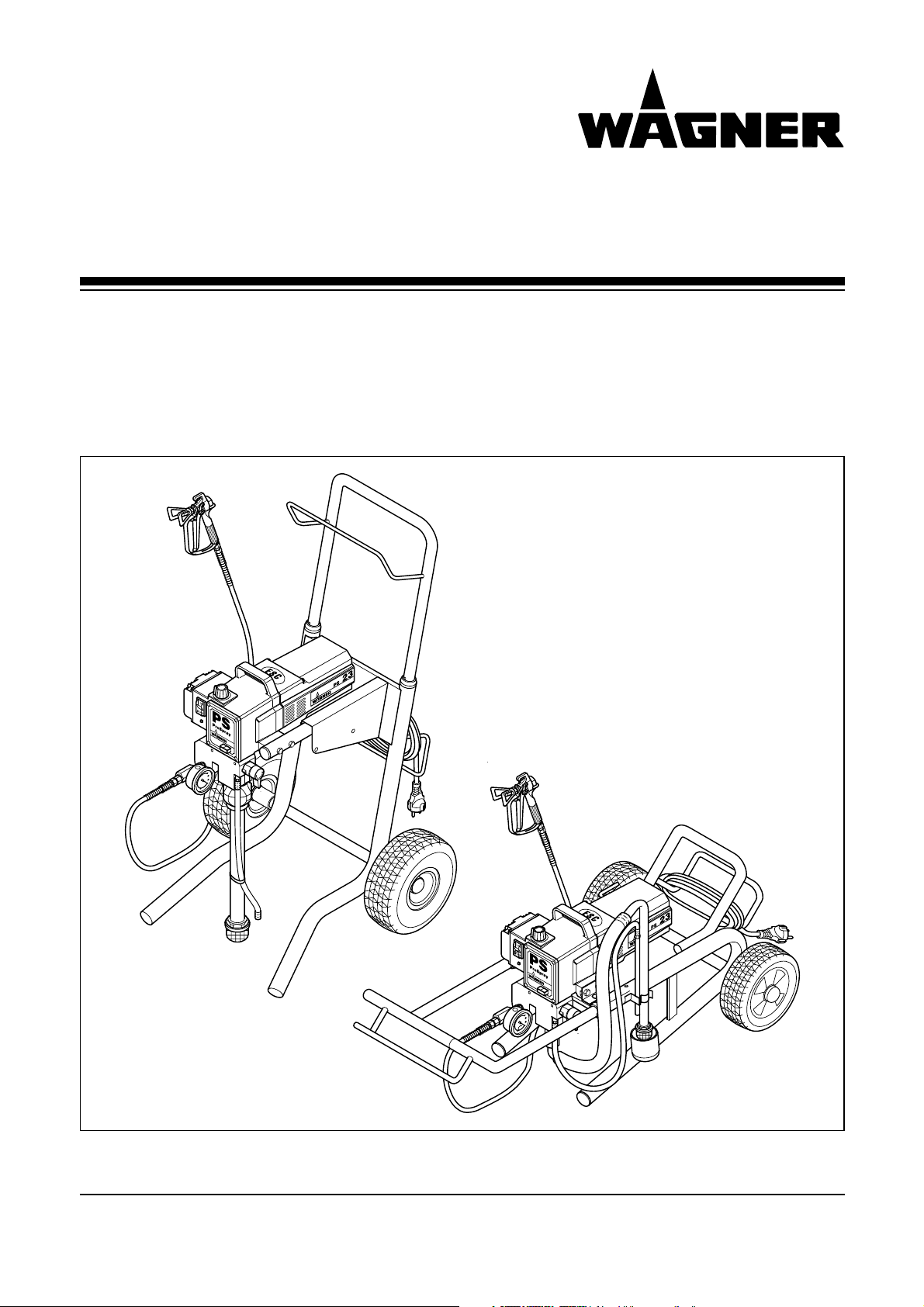
Airless Hochdruck-Spritzgerät
Airless high-pressure spraying unit
Groupe de projection à haute pression
Impianto per la verniciatura a spruzzo ad alta pressione Airless
ProSpray 23
Ausgabe 07 / 2003 0508 530
Edition
Edizione
Page 2

ProSpray 23
d
Warnung!
Niemals Finger, Hände oder andere Körperteile mit dem Spritzstrahl
in Berührung bringen!
Nie die Spritzpistole auf sich, Personen und Tiere richten.
Nie die Spritzpistole ohne Spritzstrahl-Berührungsschutz benutzen.
Behandeln Sie eine Spritzverletzung nicht als harmlose Schnittverletzung. Bei einer Hautverletzung durch Beschichtungsstoff oder
Lösemittel sofort einen Arzt aufsuchen zur schnellen, fachkundigen
Behandlung. Informieren Sie den Arzt über den verwendeten Beschichtungsstoff oder das Lösemittel.
Vor jeder Inbetriebnahme sind gemäß Betriebsanleitung
folgende Punkte zu beachten:
1. Fehlerhafte Geräte dürfen nicht benutzt werden.
2. Wagner-Spritzpistole sichern mit Sicherungshebel am
Abzugsbügel
3. Erdung sicherstellen – Der Anschluss muss über eine vorschriftsmäßig geerdete Schutzkontakt-Steckdose erfolgen.
4. zulässigen Betriebsdruck vom Hochdruckschlauch und
Spritzpistole überprüfen
5. alle Verbindungsteile auf Dichtheit prüfen
Anweisungen zur regelmäßigen Reinigung und Wartung des
Gerätes sind streng einzuhalten.
Vor allen Arbeiten am Gerät und bei jeder Arbeitspause folgende
Regeln beachten:
1. Spritzpistole und Hochdruckschlauch druckentlasten
2. Wagner-Spritzpistole sichern mit Sicherungshebel am
Abzugsbügel
3. Gerät ausschalten.
①
②
③
Achte auf Sicherheit!
Achtung, Verletzungsgefahr durch Injektion!
Airless-Geräte entwickeln extrem hohe Spritzdrücke.
Gefahr
Page 3

Seite
1. Sicherheitsvorschriften
für das Airless-Spritzen................................ 2
2. Anwendungsübersicht ................................ 4
2.1 Einsatzgebiete .............................................. 4
2.2 Beschichtungsstoffe...................................... 4
3. Gerätebeschreibung.................................... 4
3.1 Airless-Verfahren............................................ 4
3.2 Funktion des Gerätes .................................... 4
3.3 Legende zum Erklärungsbild
Gerät auf hohem Wagen................................ 5
3.4 Erklärungsbild
Gerät auf hohem Wagen................................ 5
3.5 Legende zum Erklärungsbild
Gerät auf niedrigem Wagen .......................... 6
3.6 Erklärungsbild
Gerät auf niedrigem Wagen .......................... 6
3.7 Technische Daten .......................................... 7
3.8 Transport........................................................ 7
3.9 Transport im Fahrzeug .................................. 7
4. Inbetriebnahme............................................ 7
4.1 Hochdruckschlauch, Spritzpistole
und Trennöl.................................................... 7/8
4.2 Leuchtanzeige der elektronischen
Druckeinstellung ............................................ 8
4.3 Druckregelknopf Einstellungen...................... 9
4.4 Anschluss an das Stromnetz ........................ 9
4.5 Bei Erstinbetriebnahme
Reinigung von Konservierungsmittel ............ 9
4.6 Gerät mit Beschichtungsstoff
in Betrieb nehmen.......................................... 10
5. Spritztechnik ................................................ 10
6. Handhabung des Hochdruckschlauches .. 10
6.1 Hochdruckschlauch ...................................... 10
7. Arbeitsunterbrechung ................................ 10
8. Gerätereinigung (Außerbetriebnahme) ...... 11
8.1 Gerätereinigung von außen............................ 11
8.2 Ansaugfilter.................................................... 11
8.3 Hochdruckfilter reinigen ................................ 12
8.4 Reinigung der Airless-Spritzpistole .............. 12
Seite
9. Hilfe bei Störungen ...................................... 13
10. Wartung ........................................................ 15
10.1 Allgemeine Wartung ...................................... 15
10.2 Hochdruckschlauch ...................................... 15
11. Reparaturen am Gerät ................................ 15
11.1 Entlastungsventil............................................ 15
11.2 Ein- und Auslassventil ..................................15/16
11.3 Packungen ....................................................16/17
11.4 Kohlebürsten im Motor .................................. 17
11.5 Schaltplan ProSpray 23 ................................ 18
12. Zubehör und Ersatzteile.............................. 19
12.1 Zubehör für ProSpray 23 .............................. 19
Zubehörbild für ProSpray 23 ........................ 104
12.2 Ersatzteilliste Getriebegehäuse .................... 19
Ersatzteilbild Getriebegehäuse...................... 105
12.3 Ersatzteilliste Farbstufe.................................. 20
Ersatzteilbild Farbstufe .................................. 106
12.4 Ersatzteilliste Motor ...................................... 21
Ersatzteilbild Motor........................................ 107
12.5 Ersatzteilliste hoher Wagen .......................... 21
Ersatzteilbild hoher Wagen............................ 108
12.6 Ersatzteilliste niedriger Wagen ...................... 22
Ersatzteilbild niedriger Wagen ...................... 109
12.7 Ersatzteilliste Ansaugsystem hoher Wagen .. 22
Ersatzteilbild Ansaugsystem hoher Wagen .. 110
12.8 Ersatzteilliste Ansaugsystem niedriger Wagen 22
Ersatzteilbild Ansaugsystem niedriger Wagen 110
13. Anhang.......................................................... 23
13.1 Düsenauswahl.............................................. 23
13.2 Wartung und Reinigung von Airless-
Hartmetall-Düsen .......................................... 23
13.3 Spritzpistolen-Zubehör .................................. 23
13.4 Airless-Düsen-Tabelle ................................ 24
Wagner-Servicenetz .............................................. 25
Prüfung des Gerätes.............................................. 111
Wichtiger Hinweis zur Produkthaftung................ 111
Garantieerklärung .................................................. 111
CE Konformitätserklärung .................................... 113
ProSpray 23 1
d
Inhalt
Inhalt
Page 4

1. Sicherheitsvorschriften für das
Airless-Spritzen
Die sicherheitstechnischen Anforderungen für Airless-Spritzgeräte sind geregelt in:
a) Europäische Norm „Spritz- und Sprühgeräte für
Beschichtungsstoffe – Sicherheitsanforderungen“
(EN 1953: 1998).
b) Die Berufs-Genossenschaftliche-Vorschriften
„Arbeiten mit Flüssigkeitsstrahlern“ (BGV D15)
und „Verarbeiten von Beschichtungsstoffen“
(BGV D25).
c) Richtlinien zu Bau- und Ausführungsanforderun-
gen für Flüssigkeitsstrahler (Spritzgeräte) der
gewerblichen Berufsgenossenschaften (ZH1/406).
Zum sicheren Umgang mit Airless Hochdruck-Spritzgeräten sind folgende Sicherheitsvorschriften zu beachten.
Flammpunkt
Nur Beschichtungsstoffe mit einem
Flammpunkt von 21°C oder darüber, ohne
zusätzliche Erwärmung, verspritzen.
Der Flammpunkt ist die niedrigste Tempe-
ratur, bei der sich aus dem Beschichtungsstoff Dämpfe entwickeln.
Diese Dämpfe reichen aus, um mit der über dem Beschichtungsstoff stehenden Luft ein entflammbares
Gemisch zu bilden.
Explosionsschutz
Gerät nicht benutzen in Betriebsstätten,
welche unter die Explosionsschutz-Ver-
ordnung fallen.
Explosions- und Brandgefahr bei
Spritzarbeiten durch Zündquellen
Es dürfen keine Zündquellen in der Umge-
bung vorhanden sein, wie z. B. offenes
Feuer, Rauchen von Zigaretten, Zigarren
und Tabakpfeifen, Funken, glühende
Drähte, heiße Oberflächen usw.
Verletzungsgefahr durch den
Spritzstrahl
Achtung Verletzungsgefahr durch Injektion!
Nie die Spritzpistole auf sich, Personen und Tiere
richten.
Nie die Spritzpistole ohne Spritzstrahl-Berührungs-
schutz benutzen.
Gefahr
Gefahr
Gefahr
Spritzstrahl darf mit keinem Körperteil in Berührung
kommen.
Bei Airless-Spritzpistolen auftretende hohe
Spritzdrücke können sehr gefährliche Verletzungen
verursachen. Bei Kontakt mit dem Spritzstrahl kann
Beschichtungsstoff in die Haut injiziert werden. Behandeln Sie eine Spritzverletzung nicht als harmlose
Schnittverletzung. Bei einer Hautverletzung durch
Beschichtungsstoff oder Lösemittel sofort einen Arzt
aufsuchen zur schnellen, fachkundigen Behandlung.
Informieren Sie den Arzt über den verwendeten Beschichtungsstoff oder das Lösemittel.
Spritzpistole sichern gegen unbe-
absichtigte Betätigung
Spritzpistole bei Montage oder Demontage der Düse
und bei Arbeitsunterbrechung immer sichern.
Rückstoß der Spritzpistole
Bei hohem Betriebsdruck bewirkt Ziehen des
Abzugsbügels eine Rückstoßkraft bis 15 N.
Sollten Sie nicht darauf vorbereitet sein,
kann die Hand zurückgestoßen oder das
Gleichgewicht verloren werden. Dies kann zu
Verletzungen führen.
Atemschutz zum Schutz vor Löse-
mitteldämpfen
Bei Spritzarbeiten Atemschutz tragen.
Dem Benutzer ist eine Atemschutzmaske zur Verfügung
zu stellen (Berufs-Genossenschaftliche Regeln „Regeln
für den Einsatz von Atemschutzgeräten“ (BGR 190), Berufs-Genossenschaftliche-Vorschriften „Arbeiten mit
Flüssigkeitsstrahlern” (BGV D15) und „Verarbeiten von
Beschichtungsstoffen“ (BGV D25).
Vermeidung von Berufskrankheiten
Zum Schutz der Haut sind Schutzkleidung, Handschuhe
und eventuell Hautschutzcreme erforderlich.
Vorschriften der Hersteller beachten zu den Beschichtungsstoffen, Lösemittel und Reinigungsmittel bei Aufbereitung, Verarbeitung und Gerätereinigung.
Max. Betriebsdruck
Der zulässige Betriebsdruck für die Spritzpistole,
Spritzpistolen-Zubehör und Hochdruckschlauch darf
nicht unter dem am Gerät angegebenen maximalen
Betriebsdruck von 230 bar (23 MPa) liegen.
Hochdruckschlauch (Sicherheits-
hinweis)
Elektrostatische Aufladung von Spritzpistole und Hochdruckschlauch wird über den Hochdruckschlauch abgeleitet. Deshalb muss der elektrische Widerstand zwischen den Anschlüssen des Hochdruckschlauchs gleich
oder kleiner ein Megaohm betragen.
Gefahr
2 ProSpray 23
d
Sicherheitsvorschriften
Gefahr
Page 5
Elektrostatische Aufladung
(Funken- oder Flammenbildung)
Bedingt durch die Strömungsgeschwindig-
keit des Beschichtungsstoffs beim Spritzen
kann es unter Umständen am Gerät zu elek-
trostatischen Aufladungen kommen. Diese
können bei Entladung Funken- oder Flammenbildung nach sich ziehen. Deshalb ist es notwendig,
dass das Gerät immer über die elektrische Installation
geerdet ist. Der Anschluss muss über eine vorschriftsmäßig geerdete Schutzkontakt-Steckdose erfolgen.
Gerät im Einsatz auf Baustellen
Anschluss an das Stromnetz nur über einen besonderen Speisepunkt z. B. über eine Fehlerstromschutzeinrichtung mit INF≤ 30 mA.
Gerät aufstellen
Bei Arbeiten in Räumen
Im Bereich des Gerätes dürfen sich keine
lösungsmittelhaltigen Dämpfe bilden.
Aufstellen des Gerätes auf der vom Spritzobjekt abgewandten Seite.
Mindestabstand 5 m zwischen Gerät und
Spritzpistole ist einzuhalten.
Bei Arbeiten im Freien
Es dürfen keine lösungsmittelhaltige
Dämpfe zum Gerät hin getrieben werden.
Windrichtung beachten.
Das Gerät so aufstellen, dass keine
lösungsmittelhaltigen Dämpfe zum Gerät
gelangen und sich dort ablagern.
Mindestabstand 5 m zwischen Gerät und
Spritzpistole ist einzuhalten.
Lüftung bei Spritzarbeiten
in Räumen
Es ist eine ausreichende Lüftung zur Abführung der
Lösemitteldämpfe zu gewährleisten.
Absaugeinrichtungen
Diese sind entsprechend lokaler Vorschriften vom
Geräte-Benutzer zu erstellen.
Erdung des Spritzobjekts
Das zu beschichtende Spritzobjekt muss geerdet sein.
Gefahr
i
Gefahr
Gefahr
Gerätereinigung mit Lösemittel
Bei Gerätereinigung mit Lösemittel darf nicht
in einen Behälter mit kleiner Öffnung (Spundloch) gespritzt oder gepumpt werden. Gefahr
durch Bildung eines explosionsfähigen Gas/Luftgemisches. Der Behälter muss geerdet
sein.
Gerätereinigung
Kurzschlussgefahr durch eindringendes
Wasser!
Gerät niemals mit Hochdruck- oder
Dampfhochdruckreiniger abspritzen.
Arbeiten oder Reparaturen an der
elektrischen Ausrüstung
Diese nur von einer Elektrofachkraft durchführen lassen.
Für unsachgemäße Installation wird keine Haftung übernommen.
Arbeiten an elektrischen Bauteilen
Bei allen Arbeiten den Netzstecker aus der Steckdose ziehen.
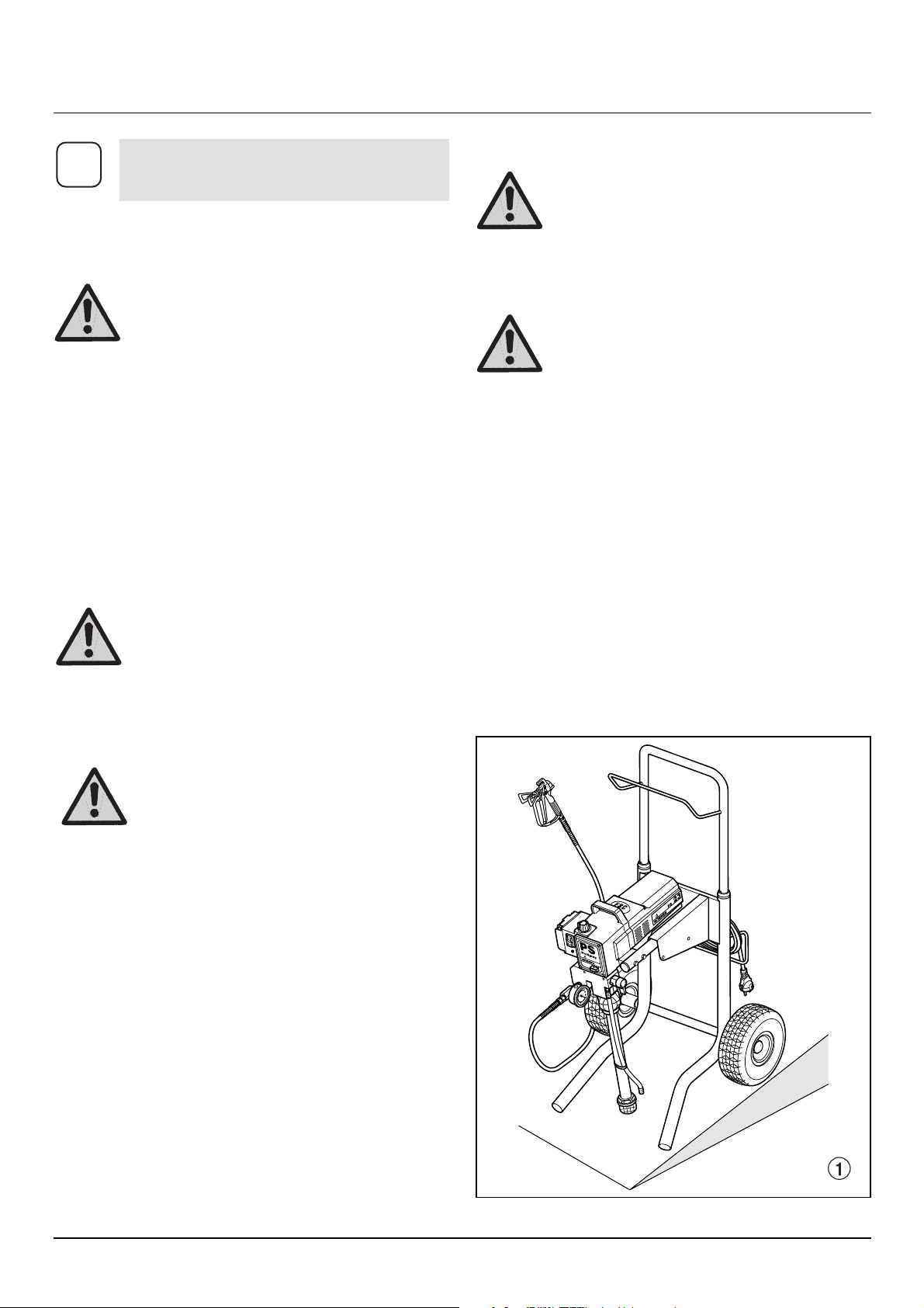
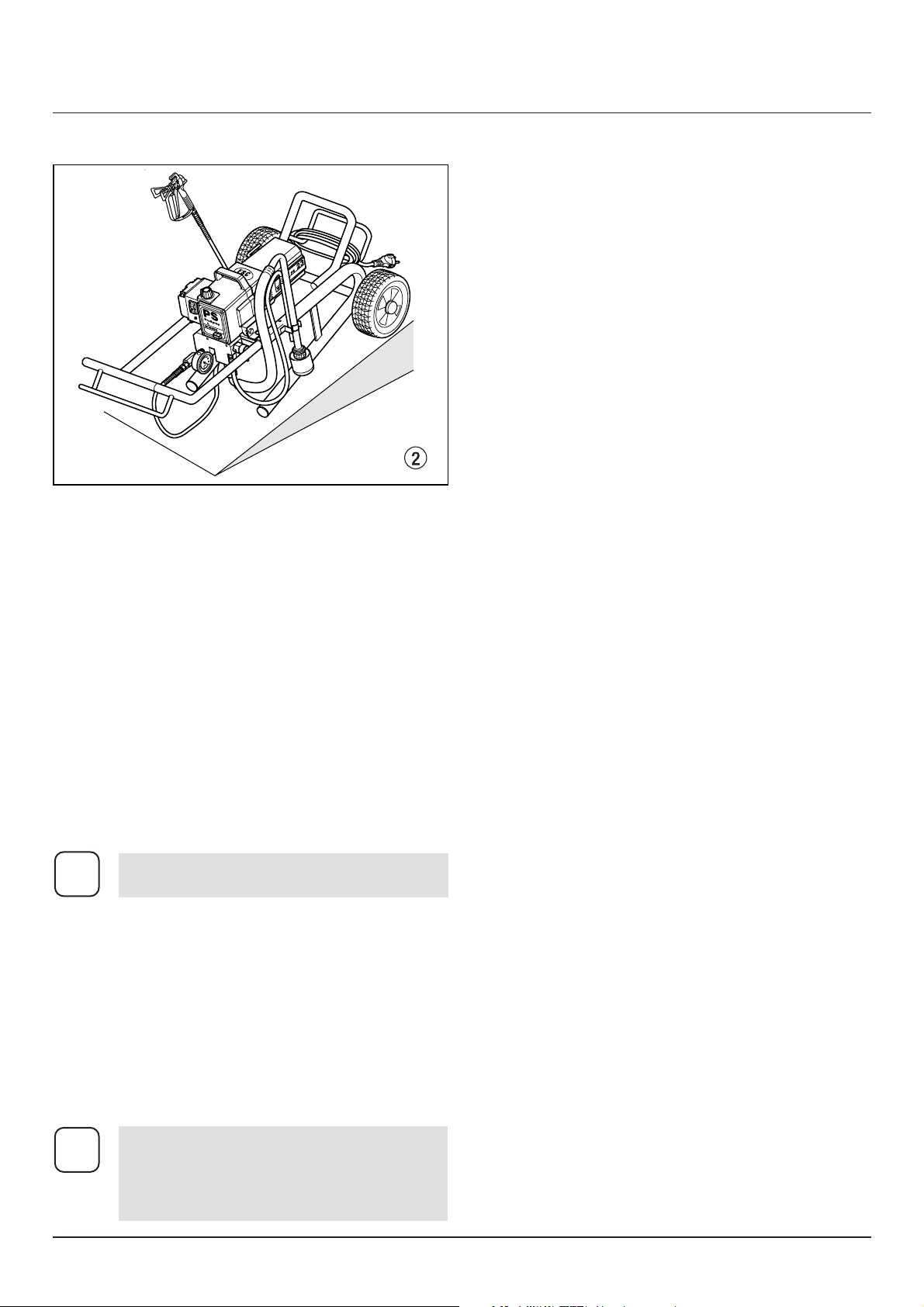
Aufstellung in unebenem Gelände
Die Vorderseite des Geräts muss nach unten zeigen, um
Wegrutschen zu vermeiden.
Gerät auf hohem Wagen
Gefahr
Gefahr
ProSpray 23 3
d
Sicherheitsvorschriften
Aus Gründen der Funktion, Sicherheit und
Lebensdauer, nur WAGNER-Original-Hochdruckschläuche verwenden.
Page 6
2. Anwendungsübersicht
2.1 Einsatzgebiete
Alle Lackieraufträge in der Werkstatt und auf der Baustelle, kleine Dispersionsarbeiten mit der Spritzpistole
oder innengespeistem Airless-Roller.
Spritzobjekt-Beispiele
Türen, Türzargen, Geländer, Möbel, Holzverkleidungen,
Zäune, Heizkörper und Stahlteile, Decken und Wände im
Innenbereich.
2.2 Beschichtungsstoffe
Verarbeitbare Beschichtungsstoffe
Wasserverdünnbare und lösemittelhaltige Lacke und
Lackfarben, Zweikomponenten Beschichtungsstoffe,
Dispersionen, Latexfarben.
Die Verarbeitung anderer Beschichtungsstoffe nur mit
Zustimmung der Firma WAGNER.
Filterung
Trotz Ansaugfilter, Einsteckfilter in der Spritzpistole und
Hochdruckfilter ist eine Filterung des Beschichtungsstoffes im allgemeinen zu empfehlen.
Beschichtungsstoff vor Arbeitsbeginn gut umrühren.
Viskosität
Mit den Geräten ist es möglich, hochviskose Beschichtungsstoffe bis etwa 25.000 mPa·s zu verarbeiten.
Lassen sich hochviskose Beschichtungsstoffe nicht ansaugen, so ist nach Herstellerangabe zu verdünnen.
Zweikomponenten-Beschichtungsstoff
Die entsprechende Verarbeitungszeit ist genau einzuhalten. Innerhalb dieser Zeit das Gerät sorgfältig mit dem
entsprechenden Reinigungsmittel durchspülen und reinigen.
Beschichtungsstoffe mit scharfkantigen Zusatzstoffen
Diese üben auf Ventile, Hochdruckschlauch, Spritzpistole
und Düse eine stark verschleißende Wirkung aus. Die
Lebensdauer dieser Teile kann sich dadurch erheblich
verkürzen.
3. Gerätebeschreibung
3.1 Airless Verfahren
Hauptanwendungsgebiete sind dicke Schichten von
höherviskosem Beschichtungsstoff bei großen Flächen
und hohem Materialeinsatz.
Eine Kolbenpumpe saugt den Beschichtungsstoff an und
fördert ihn unter Druck zur Düse. Bei einem Druck bis
max. 230 bar (23 MPa) durch die Düse gepresst, zerstäubt
der Beschichtungsstoff. Dieser hohe Druck bewirkt eine
mikrofeine Zerstäubung des Beschichtungsstoffes.
Da in diesem System keine Luft verwendet wird, bezeichnet man dieses Verfahren als AIRLESS-Verfahren
(luftlos).
Diese Art zu spritzen bringt die Vorteile von feinster Zerstäubung, nebelarmer Betriebsweise und glatter, blasenfreier Oberfläche. Neben diesen Vorteilen sind die
Arbeitsgeschwindigkeit und die große Handlichkeit zu
nennen.
3.2 Funktion des Gerätes
Zum besseren Verständnis der Funktion kurz den technischen Aufbau.
WAGNER ProSpray sind elektrisch angetriebene Hochdruckspritzgeräte.
Ein Zahnradgetriebe überträgt die Antriebskraft auf eine
Kurbelwelle. Die Kurbelwelle bewegt den Kolben der
Materialförderpumpe auf und ab.
Durch die Aufwärtsbewegung des Kolbens öffnet das
Einlassventil selbständig. Bei der Abwärtsbewegung des
Kolbens öffnet das Auslassventil.
Der Beschichtungsstoff strömt unter hohem Druck durch
den Hochdruckschlauch zur Spritzpistole. Bei Austritt
aus der Düse zerstäubt der Beschichtungsstoff.
Der Druckregler regelt die Fördermenge und den
Betriebsdruck des Beschichtungsstoffs.
4 ProSpray 23
d
Anwendungsübersicht Gerätebeschreibung
Achtung: Beim Aufrühren mit motorgetriebenen Rührwerken darauf achten, dass keine
Luftblasen eingerührt werden. Luftblasen
stören beim Spritzen, können sogar zur
Betriebsunterbrechung führen.
i
Achten Sie auf Airless-Qualität bei den zu
verarbeitenden Beschichtungsstoffen.
i
Gerät auf niedrigem Wagen
Page 7
ProSpray 23 5
d
Gerätebeschreibung
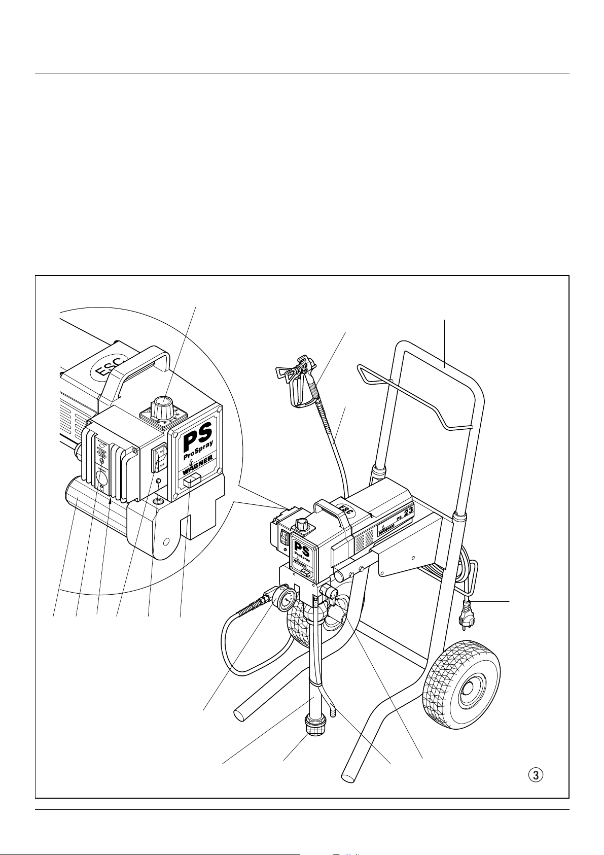
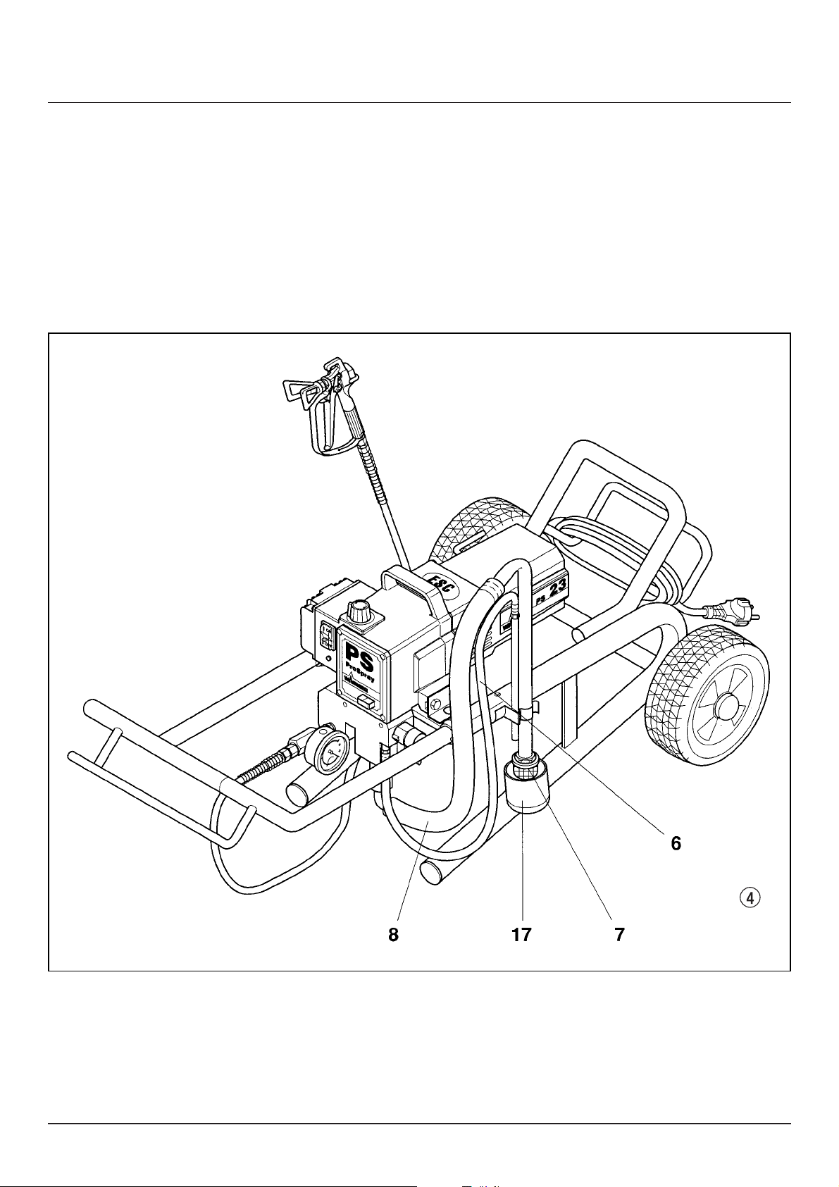
3.3 Legende zum Erklärungsbild Gerät auf hohem Wagen
1 Spritzpistole
2 Hochdruckschlauch
3 Handgriff ausziehbar
4 Geräteanschlussleitung
5 Entlastungsventil
Hebelstellung senkrecht – PRIME ( k Zirkulation)
Hebelstellung waagrecht – SPRAY ( p Spritzen)
6 Rücklaufschlauch
7 Filter
8 Ansaugrohr
9 Manometer
10 Einfüllöffnung für Trennöl (Trennöl verhindert
erhöhten Verschleiß der Packungen)
11 Kontrollleuchte zeigt Betriebsbereitschaft an
12 ON/EIN – OFF/AUS Schalter
13 Überstromschutzschalter
14 Leuchtanzeige der elektronischen Druckeinstellung
15 Hochdruckfilter
16 Druckregelknopf
1
3
4
78 56
9
10
11
2
16
1214 1315
3.4 Erklärungsbild Gerät auf hohem Wagen
Page 8
6 ProSpray 23
d
Gerätebeschreibung
6 Rücklaufschlauch
7 Filter
8 Ansaugschlauch
17 Reinigungsbehälter
3.5 Legende zum Erklärungsbild Gerät auf niedrigem Wagen
3.6 Erklärungsbild Gerät auf niedrigem Wagen
Nicht positionierte Teile wie Abbildung 3.
Page 9

ProSpray 23 7
d
Gerätebeschreibung Inbetriebnahme
3.7 Technische Daten
ProSpray 23
Spannung: 230 Volt ~, 50 Hz
max. Stromaufnahme: 5A
Absicherung: 16 A träge
Geräteanschlussleitung: 3 x 1,5 mm
2
– 6 m
Aufnahmeleistung: 1100 Watt
max. Betriebsdruck: 230 bar (23 MPa)
Volumenstrom bei 120 bar
(12 MPa) mit Wasser: 2,1 l/min
max. Düsengröße: 0,023 inch (Zoll) – 0,58 mm
max. Temperatur
des Beschichtungsstoffs: 43°C
max. Viskosität: 25.000 mPa·s
Filtereinsatz
(Standardausrüstung): 60 Maschen
Gewicht: 25 kg
Spezial-Hochdruckschlauch: DN 6 mm, 15 m, Anschluss-
gewinde M 16 x 1,5
Abmessungen Gerät auf
hohem Wagen L x B x H: 580 x 565 x 760 mm
Abmessungen Gerät auf
niedrigem Wagen L x B x H: 820 x 430 x 545 mm
max. Schalldruckpegel: 80 dB (A) *
* Messort: Abstand 1 m seitlich vom Gerät und 1,60 m über
dem Boden, 120 bar (12 MPa) Betriebsdruck, schallharter
Boden.
3.8 Transport
Gerät schieben oder ziehen.
Handgriff (Abb. 5, Pos. 1) bis zum Anschlag herausziehen. Handgriff einfahren – Druckknöpfe (2) an den Holmen eindrücken, dann Handgriff einfahren.
1
2
2
5
3
1
2
4
3.9 Transport im Fahrzeug
Hochdruckschlauch über die Aufhängung am Handgriff
aufrollen.
Gerät mit geeignetem Befestigungsmittel sichern.
4. Inbetriebnahme
4.1 Hochdruckschlauch, Spritzpistole
und Trennöl
1. An den Beschichtungsstoff-Ausgang (Abb. 6, Pos. 1)
die Manometerkombination (2) schrauben.
2. Übergangsstutzen (3) an die Manometerkombination
anschrauben.
3. Hochdruckschlauch (4) an die Manometerkombi-
nation schrauben.
4. Spritzpistole (5) mit ausgewählter Düse an den
Hochdruckschlauch anschrauben.
5. Überwurfmuttern am Hochdruckschlauch fest anzie-
hen, damit kein Beschichtungsstoff austritt.
Page 10
8 ProSpray 23
d
Inbetriebnahme
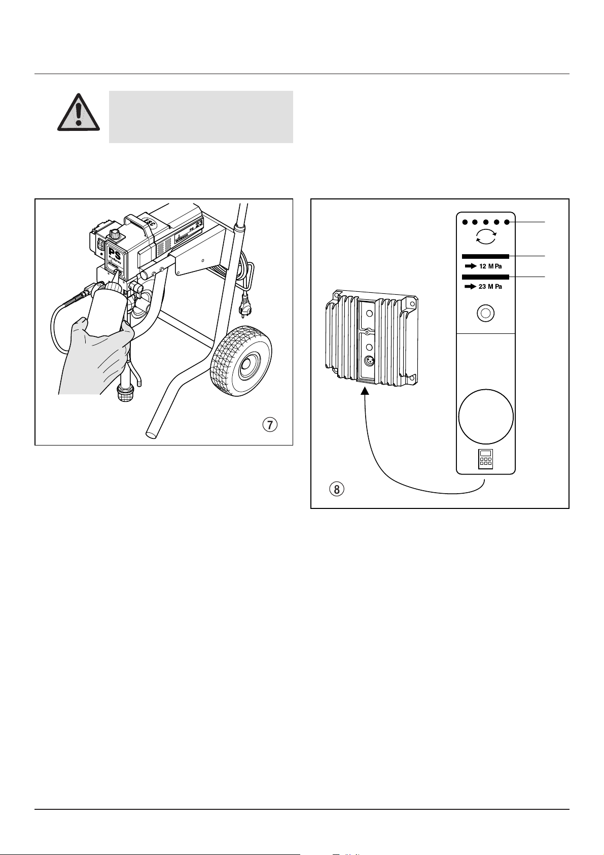
Achtung
Trennöl verhindert erhöhten
Verschleiss der Packungen.
6.
7. Trennöl einfüllen (Abb. 7). Nur soviel einfüllen, dass
kein Trennöl in den Beschichtungsstoff-Behälter
tropft.
SERVICE
1
2
3
4.2 Leuchtanzeige der elektronischen
Druckeinstellung
1. Gelb blinkend – keine Druckerzeugung
2. Gelb bis 120 bar (12 MPa)
3. Grün von 120 bar (12 MPa) bis 230 bar (23 MPa)
Page 11
ProSpray 23 9
d
Inbetriebnahme
1
2
3
4
5
6
7
8
9
4
3
2
1
4
2
5
3
1
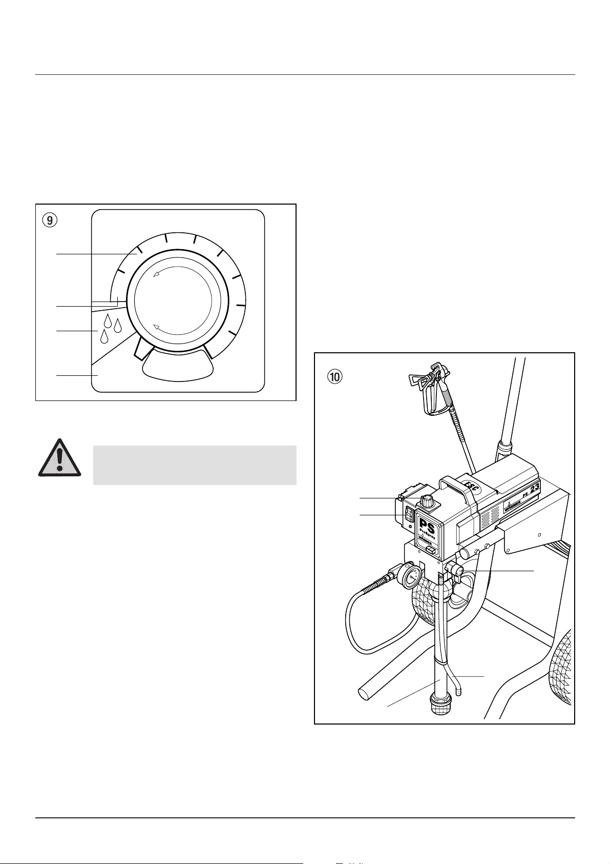
4.3 Druckregelknopf Einstellungen
(Abb. 9)
1. Minimale Druckeinstellung
2. Von minimalem Druck bis 230 bar (23 MPa)
3. Schwarze Zone – keine Druckerzeugung
4. Blaue Zone – pulsierender Druck zur Reinigung
4.4 Anschluss an das Stromnetz
Vor Anschluss an das Stromnetz darauf achten, dass die
Netzspannung übereinstimmt mit der Angabe auf dem
Leistungsschild am Gerät.
Sobald der Netzstecker angeschlossen ist, leuchtet die
grüne Kontrollleuchte unter dem ON/OFF (EIN/AUS)
Schalter.
Achtung
Der Anschluss muss über eine vorschriftsmäßig geerdete SchutzkontaktSteckdose erfolgen.
4.5 Bei Erstinbetriebnahme Reinigung
von Konservierungsmittel
1. Je nach Ausführung Ansaugrohr (Abb. 10, Pos. 1)
oder Ansaugschlauch und Rücklaufschlauch (2) in
einen Behälter mit geeignetem Reinigungsmittel einschwenken oder eintauchen.
2. Druckregelknopf (3) in der gelben Zone auf minimalen
Druck drehen.
3. Entlastungsventil (4) öffnen, Ventilstellung PRIME
( k Zirkulation).
4. Gerät einschalten (5) ON (EIN).
5. Abwarten bis Reinigungsmittel aus dem Rücklauf-
schlauch austritt.
6. Entlastungventil schließen, Ventilstellung SPRAY
( p Spritzen).
7. Abzugsbügel der Spritzpistole ziehen.
8. Reinigungsmittel aus dem Gerät in einen offenen
Sammelbehälter spritzen.
Page 12

10 ProSpray 23
d
Inbetriebnahme Arbeitsunterbrechung
4.6. Gerät mit Beschichtungsstoff
in Betrieb nehmen
1. Je nach Ausführung Ansaugrohr (Abb. 10, Pos. 1) oder
Ansaugschlauch und Rücklaufschlauch (2) in den Beschichtungsstoff-Behälter einschwenken oder eintauchen.
2. Druckregelknopf (3) in der gelben Zone auf minimalen
Druck drehen.
3. Entlastungsventil (4) öffnen, Ventilstellung PRIME ( k
Zirkulation).
4. Gerät einschalten (5) ON (EIN).
5. Abwarten bis Beschichtungsstoff aus dem Rücklauf-
schlauch austritt.
6. Entlastungsventil schließen, Ventilstellung SPRAY
( p Spritzen).
7. Spritzpistole mehrmals abziehen und in einen Sam-
melbehälter spritzen bis der Beschichtungsstoff ohne
Unterbrechung aus der Spritzpistole austritt.
8. Druck erhöhen, Druckregelknopf langsam höher dre-
hen.
Spritzbild prüfen, Druck erhöhen bis Zerstäubung einwandfrei ist.
Druckregelknopf immer auf die unterste Stellung bei
noch guter Zerstäubung drehen.
9. Das Gerät ist spritzbereit.
5. Spritztechnik
Während des Spritzvorgangs die Spritzpistole gleichmäßig führen. Bei Nichteinhaltung tritt ein unregelmäßiges Spritzbild auf. Die Spritzbewegung mit dem Arm
ausführen und nicht mit dem Handgelenk. Ein paralleler
Abstand von ca. 30 cm zwischen Spritzpistole und
Spritzobjekt einhalten. Die seitliche Abgrenzung des
Spritzstrahles soll nicht zu scharf sein. Der Spritzrand
sollte allmählich auflockern, damit beim nächsten Durchgang leicht überlappt werden kann. Spritzpistole immer
parallel und im Winkel von 90° zur Spritzfläche führen, so
entsteht am wenigsten Farbnebel.
Beim Auftreten sehr scharfer Randzonen und
Streifen im Spritzstrahl – Betriebsdruck erhöhen oder Beschichtungsstoff verdünnen.
i
6. Handhabung des Hochdruckschlauches
Scharfes Biegen oder Knicken des Hochdruckschlauches vermeiden, kleinster Biegeradius etwa 20 cm.
Hochdruckschlauch nicht überfahren, sowie vor scharfen
Gegenständen und Kanten schützen.
6.1 Hochdruckschlauch
Das Gerät ist mit einem speziell für Kolbenpumpen geeigneten Hochdruckschlauch ausgerüstet.
Aus Gründen der Funktion, Sicherheit und Lebensdauer
nur WAGNER Orginal-Hochdruckschläuche verwenden.
7. Arbeitsunterbrechung
1. Entlastungsventil öffnen, Ventilstellung PRIME
( k Zirkulation).
2. Gerät ausschalten OFF (AUS).
3. Druckregelknopf bis zum Anschlag in die schwarze
Zone drehen (keine Druckerzeugung)
4. Abzugsbügel der Spritzpistole ziehen, um Hoch-
druckschlauch und Spritzpistole vom Druck zu entlasten.
5. Spritzpistole sichern, siehe Betriebsanleitung der
Spritzpistole.
6. Falls eine Standarddüse gereinigt werden soll, siehe
Seite 23, Punkt 13.2.
Ist eine andere Düsenausführung montiert, dann nach
entsprechender Betriebsanleitung vorgehen.
7. Je nach Ausführung Ansaugrohr oder Ansaug-
schlauch und Rücklaufschlauch im Beschichtungsstoff eingetaucht lassen oder in ein entsprechendes
Reinigungsmittel einschwenken oder eintauchen.
Verletzungsgefahr durch undichten Hochdruckschlauch. Beschädigten Hochdruckschlauch sofort ersetzen.
Niemals defekten Hochdruckschlauch
selbst reparieren!
Aus Gründen der Funktion, Sicherheit und
Lebensdauer nur WAGNER Original-Hochdruckschläuche verwenden.
i
Gefahr
Achtung
Beim Einsatz von schnelltrocknenden
– oder Zweikomponenten-Beschichtungsstoff, Gerät unbedingt innerhalb
der Verarbeitungszeit mit geeignetem
Reinigungsmittel durchspülen.
Page 13

ProSpray 23 11
d
Gerätereinigung (Außerbetriebnahme)
8. Gerätereinigung
(Außerbetriebnahme)
Sauberkeit ist die sicherste Gewährleistung für einen
störungsfreien Betrieb. Nach Beendigung der Spritzarbeiten Gerät reinigen. Auf keinen Fall dürfen Beschichtungsstoffe im Gerät antrocknen und sich festsetzen.
Das zur Reinigung verwendete Reinigungsmittel (nur mit
einem Flammpunkt über 21° C) muss dem Beschichtungsstoff entsprechen.
• Spritzpistole sichern, siehe Betriebsanleitung der
Spritzpistole
Düse reinigen und demontieren.
Standarddüse siehe Seite 23, Punkt 13.2.
Ist eine andere Düsenausführung montiert, dann nach
entsprechender Betriebsanleitung vorgehen.
1. Je nach Ausführung Ansaugrohr oder Ansaug-
schlauch aus dem Beschichtungsstoff herausschwenken oder herausnehmen.
2. Entlastungsventil schließen, Ventilstellung SPRAY
(p Spritzen).
3. Gerät einschalten ON (EIN).
4. Abzugsbügel an der Spritzpistole ziehen, um restli-
chen Beschichtungsstoff aus dem Ansaugrohr oder
Ansaugschlauch, Hochdruckschlauch und der
Spritzpistole in einen offenen Behälter zu pumpen.
5. Je nach Ausführung Ansaugrohr oder Ansaug-
schlauch mit Rücklaufschlauch in einen Behälter mit
geeignetem Reinigungsmittel einschwenken oder
eintauchen.
6. Druckregelknopf in die blaue Zone drehen – pulsie-
render Druck zur Reinigung.
7. Entlastungsventil öffnen, Ventilstellung PRIME
( k Zirkulation).
8. Geeignetes Reinigungsmittel einige Minuten im
Kreislauf pumpen.
9. Entlastungsventil schließen, Ventilstellung SPRAY
( p Spritzen).
10. Abzugsbügel an der Spritzpistole ziehen.
11. Restliches Reinigungsmittel in einen offenen Behälter
pumpen, bis das Gerät leer ist.
12. Gerät ausschalten OFF (AUS).
Bei lösemittelhaltigen Beschichtungsstoffen muss der Behälter geerdet werden.
Achtung
Vorsicht! Nicht in Behälter mit kleiner
Öffnung (Spundloch) pumpen oder
spritzen!
Siehe Sicherheitsvorschriften.
Gefahr
8.1 Gerätereinigung von außen
Gerät außen mit einem in geeignetem Reinigungsmittel
getränktem Tuch abwischen.
8.2 Ansaugfilter
– Filter (Abb. 11) vom Ansaugrohr abschrauben.
– Filter reinigen oder austauschen.
Reinigung mit einem harten Pinsel und entsprechendem Reinigungsmittel durchführen.
Zuerst Netzstecker aus der Steckdose
ziehen.
Gefahr
Kurzschlussgefahr durch eindringendes Wasser!
Gerät niemals mit Hochdruck- oder
Dampfhochdruckreiniger abspritzen.
Gefahr
Ein sauberer Ansaugfilter gewährleistet stets
maximale Fördermenge, konstanten Spritzdruck und einwandfreies Funktionieren des
Gerätes.
i
Page 14
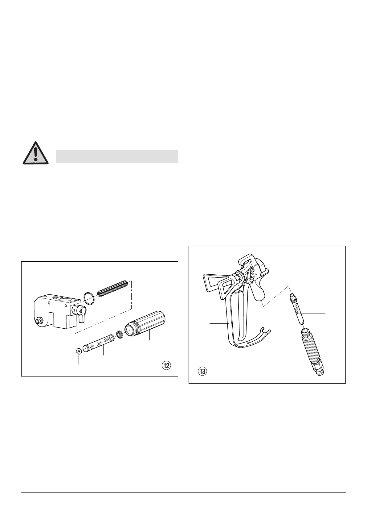
8.3 Hochdruckfilter reinigen
Filterpatrone regelmäßig reinigen.
Ein verschmutzter oder verstopfter Hochdruckfilter verur-
sacht ein schlechtes Spritzbild oder eine verstopfte Düse.
1. Druckregelknopf bis zum Anschlag in die schwarze
Zone drehen (kein Druck).
2. Entlastungsventil öffnen, Ventilstellung PRIME
( k Zirkulation).
3. Gerät ausschalten OFF (AUS).
4. Filtergehäuse (Abb. 12, Pos. 1) mit Bandschlüssel ab-
schrauben.
5. Filterpatrone (2) von der Stützfeder (3) abziehen.
6. Alle Teile mit entsprechendem Reinigungsmittel reini-
gen. Wenn notwendig, Filterpatrone austauschen.
7. O-Ring (4) prüfen, wenn notwendig austauschen.
8. Stützscheibe (5) an die Stützfeder (3) anlegen. Filter-
patrone (2) über die Stützfeder schieben.
9. Filtergehäuse (1) einschrauben und mit Bandschlüssel
bis zum Anschlag anziehen.
12 ProSpray 23
d
Gerätereinigung (Außerbetriebnahme)
Netzstecker aus der Steckdose ziehen.
Gefahr
8.4 Reinigung der Airless-Spritzpistole
– Airless-Spritzpistole bei niedrigem Betriebsdruck mit
geeignetem Reinigungsmittel durchspülen.
– Düse gründlich mit geeignetem Reinigungsmittel rei-
nigen, so dass keine Beschichtungsstoffreste zurückbleiben.
– Airless-Spritzpistole außen gründlich reinigen.
Einsteckfilter in der Airless-Spritzpistole
Demontage (Abb. 13)
1. Schutzbügel (1) kräftig nach vorne ziehen.
2. Griff (2) aus dem Pistolengehäuse schrauben. Einsteckfilter (3) herausziehen.
3. Einsteckfilter verstopft oder defekt – ersetzen.
Montage
1. Einsteckfilter (3) mit dem längeren Konus in das Pistolengehäuse stecken.
2. Griff (2) in das Pistolengehäuse einschrauben und anziehen.
3. Schutzbügel (1) einrasten.
4
3
5
2
1
3
Warning:
keep clear
of tip
250 bar
max.3600 psi
2
1
Page 15

ProSpray 23 13
d
Hilfe bei Störungen
9. Hilfe bei Störungen
Gerät läuft nicht an
Gerät saugt nicht an
Gerät saugt an, aber es
kommt zu keinem Druckaufbau
Kontrollleuchte zeigt keine
Betriebsbereitschaft an.
Keine Spannung vorhanden.
Bei Überbelastung schaltet
sich das Gerät automatisch ab.
Das Gerät schaltet nicht
selbstständig wieder ein.
Druckeinstellung zu niedrig.
ON/OFF (EIN/AUS) Schalter
defekt.
Kohlebürsten im Motor
abgenützt.
Entlastungsventil ist auf SPRAY
( p Spritzen) eingestellt.
Filter ragt über den Flüssigkeitsspiegel hinaus und saugt
Luft an.
Filter verstopft.
Gerät auf hohem Wagen
Ansaugrohr lose, das heißt,
das Gerät saugt Nebenluft.
Gerät auf niedrigem Wagen
Ansaugschlauch lose,
das heißt, das Gerät saugt
Nebenluft.
Düse stark verschlissen.
Düse zu groß.
Druckeinstellung zu niedrig.
Filter verstopft.
Beschichtungsstoff fließt über
den Rücklaufschlauch, wenn
das Entlastungsventil in Stellung SPRAY (p Spritzen) steht.
Packungen verklebt oder
verschlissen.
Ventilkugeln verschlissen.
Ventilsitze verschlissen.
Spannungsversorgung prüfen.
Gerät ausschalten OFF (AUS). Nach 2 – 3 Minuten
Überstromschutzschalter drücken, Gerät wieder einschalten ON (EIN).
Druckregelknopf höher drehen.
Austauschen
Austauschen
Entlastungsventil auf PRIME ( k Zirkulation) stellen.
Beschichtungsstoff nachfüllen.
Filter reinigen oder austauschen.
Anschlussstellen reinigen. Ansaugrohr anziehen.
Anschlussstellen reinigen falls notwendig O-Ringe
austauschen. Ansaugschlauch mit Halteklammer
sichern.
Austauschen
Wahl einer kleineren Düse,
siehe Düsentabelle Seite 24.
Druckregelknopf auf höhere Ziffer drehen.
Filter reinigen oder austauschen.
Entlastungsventil demontieren und reinigen oder austauschen.
Packungen ausbauen, reinigen oder austauschen.
Ventilkugeln ausbauen und austauschen.
Ventilsitze ausbauen und austauschen.
Art der Störung Mögliche Ursache Maßnahme zur Behebung der Störung
Page 16

14 ProSpray 23
d
Hilfe bei Störungen
Beschichtungsstoff tritt
oben aus der Farbstufe
Erhöhte Pulsation an der
Spritzpistole
Schlechtes Spritzbild
Gerät verliert an Leistung
Obere Packung ist verschlissen.
Kolben ist verschlissen.
Falscher Hochdruckschlauchtyp.
Düse verschlissen oder zu groß.
Zu hoher Druck.
Zu große Düse für den zu
verspritzenden Beschichtungsstoff.
Druckeinstellung nicht korrekt.
Zu niedrige Fördermenge.
Beschichtungsstoff hat zu hohe
Viskosität.
Druckeinstellung ist zu niedrig.
Packung ausbauen und austauschen.
Kolben ausbauen und austauschen.
Aus Gründen der Funktion, Sicherheit und Lebensdauer nur WAGNER Original-Hochdruckschläuche
verwenden.
Düse austauschen.
Druckregelknopf auf niedrigere Ziffer drehen.
Düse austauschen, siehe Düsentabelle Seite 24.
Druckregelknopf drehen bis ein zufriedenstellendes
Spritzbild erreicht wird.
Alle Filter reinigen oder austauschen.
Entsprechend Herstellerangabe verdünnen.
Druckregelknopf auf höhere Ziffer drehen.
Art der Störung Mögliche Ursache Maßnahme zur Behebung der Störung
Page 17
ProSpray 23 15
d
Wartung Reparaturen am Gerät
10. Wartung
10.1 Allgemeine Wartung
Die Wartung des Gerätes soll einmal jährlich durch den
Wagner-Service durchgeführt werden.
1. Hochdruckschläuche, Geräteanschlussleitung und
Stecker auf Beschädigung prüfen.
2. Einlass-, Auslassventil und Filter auf Verschleiß prüfen.
10.2 Hochdruckschlauch
Hochdruckschlauch optisch auf eventuell vorhandene
Einschnitte oder Ausbeulungen, insbesondere am Übergang in die Armatur, prüfen. Überwurfmuttern müssen
sich frei drehen lassen.
11. Reparaturen am Gerät
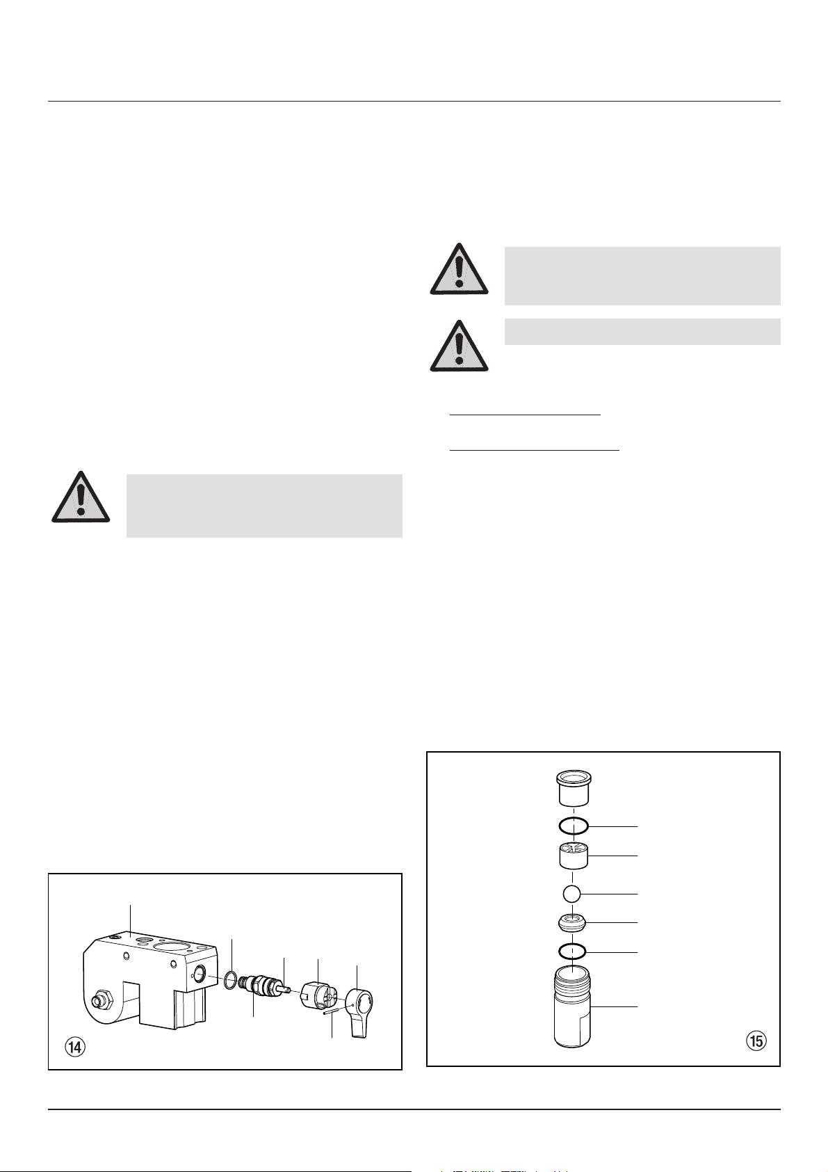
11.1 Entlastungsventil
1. Kerbstift (Abb. 14, Pos. 1) mit einem Durchschlag von
2 mm aus dem Entlastungsventilgriff (2) entfernen.
2. Entlastungsventilgriff (2) und Mitnehmer (3) abziehen.
3. Ventilgehäuse (4) komplett mit Rollgabelschlüssel ab-
schrauben.
4. Sicherstellen, dass die Dichtung (5) richtig sitzt, dann
neues Ventilgehäuse (4) komplett in das Farbstufengehäuse (6) einschrauben. Mit Rollgabelschlüssel anziehen.
5. Mitnehmer (3) ausrichten auf die Bohrung im Farbstu-
fengehäuse (6). Mitnehmer aufschieben und mit Maschinenfett einstreichen.
6. Bohrung in der Ventilwelle (7) und im Entlastungsven-
tilgriff (2) in Übereinstimmung bringen.
7. Kerbstift (1) einsetzen und Entlastungsventilgriff in
Stellung PRIME/SPRAY stellen.
11.2 Ein- und Auslassventil
1. Die vier Schrauben im Frontdeckel entfernen, Frontdeckel abnehmen.
2. Gerät einschalten ON (EIN) und so auschalten OFF
(AUS), dass der Pleuel in der untersten Hubstellung
steht.
3.
4. Gerät auf hohem W
agen
Ansaugrohr abschrauben.
Gerät auf niedrigem W
agen
Halteklammer vom Anschlussbogen am Ansaugschlauch entfernen, Ansaugschlauch abziehen.
5. Rücklaufschlauch abschrauben.
6. Gerät um 90° nach hinten schwenken zum leichteren
Arbeiten an der Materialförderpumpe.
7. Einlassventilgehäuse (Abb. 15, Pos. 1) aus dem
Farbstufengehäuse schrauben.
8. Untere Dichtung (2), untere Kugelführung (3), Einlassventilkugel (4), Einlassventilsitz (5) und O-Ring (6)
ausbauen.
9. Alle Teile mit entsprechendem Reinigungsmittel reinigen.
Einlassventilgehäuse (1), Einlassventilsitz (5) und Einlassventilkugel (4) auf Verschleiß prüfen, wenn notwendig Teile austauschen. Verschlissener Einlassventilsitz (5), falls er auf einer Seite unbenützt ist, umgedreht einbauen.
Gefahr
Gerät ausschalten OFF (AUS).
Vor allen Reparaturen – Netzstecker
aus der Steckdose ziehen.
Gefahr
Quetschgefahr – nicht mit den Fingern
oder Werkzeug zwischen die sich bewegenden Teile fassen.
Gefahr
Netzstecker aus der Steckdose ziehen.
6
5
7
3
2
1
4
2
3
4
5
6
1
Page 18
16 ProSpray 23
d
Reparaturen am Gerät
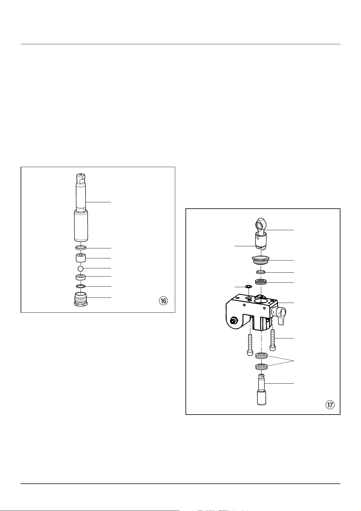
10. Auslassventilgehäuse (Abb. 16, Pos. 7) mit Rollgabelschlüssel aus dem Kolben (8) schrauben.
11. Obere Dichtung (9), obere Kugelführung (10),
Auslassventilkugel (11), Auslassventilsitz (12) und
O-Ring (13) ausbauen.
12. Alle Teile mit entsprechendem Reinigungsmittel reinigen. Auslassventilgehäuse (7), Auslassventilsitz (12),
Auslassventilkugel (11) und obere Kugelführung (10)
auf Verschleiß prüfen, wenn notwendig, Teile austauschen. Verschlissener Auslassventilsitz (12), falls er
auf einer Seite unbenützt ist, umgedreht einbauen.
13. Montage in umgekehrter Reihenfolge durchführen.
O-Ring (Abb. 15, Pos. 6) mit Maschinenfett einstreichen und auf richtigen Sitz im Einlassventilgehäuse
(Abb. 15, Pos. 1) achten.
8
9
10
11
12
13
7
5
6
7
8
1
2
4
10
9
3
11.3 Packungen
1. Einlassventilgehäuse ausbauen entsprechend den
Schritten unter Kapitel 11.2, Seite 15.
2. Es ist nicht notwendig, das Auslassventil auszubauen.
3. Beide Zylinderkopfschrauben (Abb. 17, Pos. 1) mit
einem Sechskantschraubendreher 3/8 inch aus dem
Farbstufengehäuse (2) schrauben.
4. Farbstufengehäuse (2) etwa 15 mm vom Getriebegehäuse abziehen.
5. Farbstufengehäuse (2) mit Kolben (3) nach vorne
ziehen, bis der Kolben aus dem T-Schlitz (4) des
Pleuels (5) frei ist.
6. Kolben (3) aus dem Farbstufengehäuse (2) nach
unten herausschieben.
7. Führungsmutter (6) aus dem Farbstufengehäuse (2)
schrauben, Kolbenführung (7) entfernen.
8. Obere Packung (8) und untere Packungen (9) aus
dem Farbstufengehäuse (2) entfernen.
Page 19

ProSpray 23 17
d
Reparaturen am Gerät
1
2
1
2
5
2
3
4
7
6
1
9. Farbstufengehäuse (2) reinigen.
10. Obere Packung (8) und untere Packungen (9) mit
Maschinenfett einstreichen.
11. Obere Packung (Abb. 18) mit O-Ring (1) und vorstehender Lippe (2) nach unten einsetzen.
12. Untere Packungen (Abb. 19) mit O-Ring (1) und vorstehender Lippe (2) nach oben einsetzen.
13. Kolbenführung (Abb. 17, Pos. 7) in die Führungsmutter (6) einsetzen. Führungsmutter (6) in das Farbstufengehäuse (2) einschrauben und von Hand anziehen.
14. Montagewerkzeug (im Lieferumfang Ersatz-Packungen) für den Kolben (3) von oben auf den Kolben
schieben.
15. Montagewerkzeug und Kolben (3) mit Maschinenfett
einstreichen.
16. Kolben (3) von unten in das Farbstufengehäuse (2)
durch die unteren Packungen (9) einführen. Mit einem Gummihammer leicht von unten auf den Kolben
(3) schlagen, bis er oberhalb des Farbstufengehäuses zu sehen ist.
17. Montagewerkzeug vom Kolben (3) entfernen.
18. Mit Rollgabelschlüssel Führungsmutter (6) vorsichtig
anziehen.
19. Oberes Ende des Kolbens (3) in den T-Schlitz (4) des
Pleuels (5) einschieben.
20. Farbstufengehäuse (2) an das Getriebegehäuse fixieren. Darauf achten, dass der Druckgeber die Druckgeberdichtung (10) nicht beschädigt.
21. Farbstufengehäuse (2) am Getriebegehäuse fest anschrauben.
22. O-Ring (Abb. 15, Pos. 6) zwischen Farbstufengehäuse (2) und Einlassventilgehäuse mit Maschinenfett
einstreichen. Einlassventilgehäuse in das Farbstufengehäuse einschrauben.
23. Gerät auf hohem Wagen
Ansaugrohr anschrauben. Rücklaufschlauch anschrauben und am Ansaugrohr anklammern.
Gerät auf niedrigem Wagen
Anschlussbogen vom Ansaugschlauch in das
Einlassventilgehäuse (Abb. 15, Pos. 1) schieben und
mit Halteklammer sichern. Rücklaufschlauch anschrauben und am Ansaugschlauch anklammern.
24. Frontdeckel montieren.
11.4 Kohlebürsten im Motor
1. Vier Schrauben (Abb. 20, Pos. 1) an der Motorabdeckung (2) entfernen. Motorabdeckung abnehmen.
2. Zwei Schrauben (3) an den Halbschalen (4) entfernen. Halbschalen abnehmen.
3. Mit einem kleinen Schraubendreher die beiden Abdeckungen (5) abheben.
4. Rote Litze (6) und schwarze Litze (7) von der entsprechenden Kohlebürste herausziehen.
5. Neue Kohlebürste einsetzen und die Abdeckung (5)
einschnappen lassen.
6. Rote Litze (6) und schwarze Litze (7) an der entsprechenden Kohlebürste aufstecken.
7. Beide Halbschalen (4) anschrauben.
8. Motorabdeckung (2) über den Motor schieben und
mit den vier Schrauben (1) befestigen.
Page 20

18 ProSpray 23
d
Reparaturen am Gerät
11.5 Schaltplan ProSpray 23
Motor
schwarz
schwarz
Kondensatoren
schwarz
rot
rot
rot
rot
weißweiß
schwarz
Gleich-
richter
Netzstecker
Druckgeber
Erdung
blau
grün
grün
grün
Betriebs-
anzeige
braun
blau
Schalter
blau
grün gelb
Eingang
braun
braun
Ausgang
Endstör-
filter
Potentiometer
Überstromschutz-
schalter
Elektronik-
regler
Erdung
weiß
schwarz
Motor
TP5
TP4
JP1 JP3 TP3
TP2
TP1
Neutral
Motor
Schalter
schwarz
schwarz
Page 21

Pos. Best. Nr. Benennung
4 9984 510 Hochdruckschlauch
DN 4 mm, 7,5 m mit Edelstahlnippel
9984 507 Hochdruckschlauch
DN 6 mm, 15 m für Dispersion
9984 562 Hochdruckschlauch
DN 6 mm, 30 m für Dispersion
5 0034 030 Doppelstutzen zum Kuppeln von
Hochdruckschläuchen
6 0034 950 Metex-Reuse
Reuse zur Vorfilterung von
Beschichtungsstoff im Gebinde.
Ansaugrohr direkt in die Reuse stellen.
0034 952 Siebpaket (5 Stück) für Lack
0034 951 Siebpaket (5 Stück) für Dispersion
ProSpray 23 19
d
Zubehör und Ersatzteile
12. Zubehör und Ersatzteile
12.1 Zubehör für ProSpray 23 (Zubehörbild, siehe Seite 104)
Pos. Best. Nr. Benennung
1 0149 040 Spritzpistole G 08
(Ausführung in Aluminium)
0335 002 Spritzpistole G 12
(Ausführung in Aluminium)
0257 001 Spritzpistole AG-09 S
(Ausführung in Edelstahl)
2 0096 004 Auslegerpistole 30 cm
0096 019 Auslegerpistole 100 cm
0096 005 Auslegerpistole 150 cm
0096 006 Auslegerpistole 270 cm
3 0345 010 Inline Roller IR-100
12.2 Ersatzteilliste Getriebegehäuse
(Ersatzteilbild, siehe Seite 105)
Pos. Best. Nr. Benennung
1 0508 571 Schraube
2 0508 570 Frontdeckel
3 –––––––– Kontrollleuchte
4 9850 936 EIN/AUS Schalter (230 V~, 50 Hz)
5 0508 572 Kurbelwelle
6 0508 573 Anlaufscheibe
7 0507 938 Getrieberad, Stufe 2
8 0508 200 Getriebegehäuse
9 0508 208 Pleuel
10 0507 748 Verschlusskappe
14 0507 749 Mutter
15 0507 740 Druckregelknopf
16 0508 575 Platte für Potentiometer
18 0507 973 Potentiometer
19 0508 580 Überstromschutzschalter
Pos. Best. Nr. Benennung
20 0508 581 Schraube
23 0508 643 Kondensator-Gleichrichter-Set
(230 V~, 50 Hz) mit Pos. 24
24 9802 244 Schraube
25 0508 656 Elektronische Druckeinstellung
(mit Pos. 28, 29, 30)
28 0508 621 Abdeckung, LED
29 0508 657 Schraube
30 0507 751 Verschlusskappe
31 0508 658 Entstörmodul
33 0508 654 Druckgeber
34 9850 644 Kabelverschraubung
35 9800 340 Schraube
36 0261 352 Geräteanschlussleitung
H07RN-F3 G 1,5 – 6 m
Page 22

20 ProSpray 23
d
Zubehör und Ersatzteile
Pos. Best. Nr. Benennung
1 0034 041 Übergangsstutzen M 16 x 1,5
2 0340 256 Manometerkombination
3 3505 045 Doppelstutzen
4 0508 689 Farbstufengehäuse
5 0507 517 Verschlussstopfen
6 0508 666* Obere Packung
7 0508 665* Kolbenführung
8 0508 664 Führungsmutter
10 0508 604 O-Ring
11 0508 749 Stützfeder
12 0508 603 Stützscheibe
13 0508 449 Filterpatrone, 30 Maschen
0508 748 Filterpatrone, 60 Maschen (Standardausrüstung)
0508 450 Filterpatrone, 100 Maschen
14 0508 602 Konusfeder
15 0508 601 Filtergehäuse
18 0508 212 Entlastungsventil
19 0507 745 Dichtung
20 0508 683 Mitnehmer
21 0508 744 Entlastungsventilgriff
22 0508 745 Kerbstift
23 0508 684 Doppelnippel
27 0508 690 Einlassventilgehäuse (Gerät mit hohem Wagen)
0508 680 Einlassventilgehäuse (Gerät mit niedrigem Wagen)
28 3500 203* O-Ring
29 0508 679 Einlassventilsitz
30 0508 678* Einlassventilkugel
31 0508 677 Untere Kugelführung
32 0508 739* Untere Dichtung
33 0508 676 Buchse
34 0508 211 Kolben (Pos. 35 -> 41)
35 0508 675 Auslassventilgehäuse
36 0508 674* O-Ring
37 0508 673 Auslassventilsitz
38 0508 672* Auslassventilkugel
39 0508 671 Obere Kugelführung
40 0508 670* Obere Dichtung
41 0508 669 Kolben
42 0508 668* Untere Packung (2)
43 0508 553 Zylinderkopfschraube (2)
0508 214* Service-Set Packungen mit Maschinenfett
und Montagewerkzeug
0508 619 Trennöl 118 ml (verhindert erhöhten Verschleiß
der Packungen)
0508 620 Reiniger 118 ml (für die Farbstufe innen)
9984 507 Hochdruckschlauch DN 6 mm, 15 m
12.3 Ersatzteilliste Farbstufe
(Ersatzteilbild, siehe Seite 106)
Page 23

ProSpray 23 21
d
Zubehör und Ersatzteile
12.4 Ersatzteilliste Motor
(Ersatzteilbild, siehe Seite 107)
Pos. Best. Nr. Benennung
1 0508 643 Kondensator-Gleichrichter-Set (230 V~, 50 Hz)
2 0508 559 Zylinderkopfschraube (4)
3 0508 644 Litzensatz (schwarz)
4 0508 645 Kohlebürsten-Set
5 0508 646 Halbschale
6 9802 891 Schraube (2)
7 0508 562 Dichtung
8 0508 648 Lüfter
9 0508 649 Schraube
13 0508 563 Schraube (4)
14 0508 564 Gummitülle
15 0508 688 Motorabdeckung
16 0508 650 Litzensatz (rot)
17 0508 215 Motor (230 V~, 50 Hz)
12.5 Ersatzteilliste hoher Wagen
(Ersatzteilbild, siehe Seite 108)
Pos. Best. Nr. Benennung
1 0508 583 Handgriff
2 9841 504 Haltefeder
3 0295 607 Führungsbuchse
4 0295 609 Scheibe
5 0295 610 Spannhülse
6 0295 608 Schraube
7 0295 606 Scheibe
8 0507 956 Spannhülse
9 0294 534 Scheibe
10 9890 104 Radkappe
11 0508 584 Grundgestell
12 0295 617 Verschlussstopfen
13 0278 373 Rad
14 0508 586 Verschlussstopfen
15 0508 555 Sechskantschraube
Page 24

22 ProSpray 23
d
Zubehör und Ersatzteile
Pos. Best. Nr. Benennung
1 0507 956 Spannhülse
2 0294 534 Scheibe
3 0270 394 Rad
4 9890 104 Radkappe
5 0508 589 Grundgestell
6 0295 617 Verschlussstopfen
10 0295 615 Sechskantmutter
11 0507 955 Schraube
12 0508 591 Handgriff
13 9841 504 Haltefeder
Pos. Best. Nr. Benennung
14 0295 607 Führungsbuchse
15 0295 609 Scheibe
16 0295 610 Spannhülse
17 0295 606 Scheibe
18 0295 608 Schraube
19 0508 590 Sechskantschraube
20 0508 381 Reinigungsbehälter
21 0295 618 Schraube
22 0508 588 Montagewinkel
24 9885 546 Verschlussstopfen
12.6 Ersatzteilliste niedriger Wagen
(Ersatzteilbild, siehe Seite 109)
Pos. Best. Nr. Benennung
1 0508 692 Ansaugrohr
2 0508 747 Filter, 10 Maschen
3 0508 556 Rücklaufschlauch
4 0507 783 Klammer
12.7 Ersatzteilliste Ansaugsystem hoher Wagen
(Ersatzteilbild, siehe Seite 110)
Pos. Best. Nr. Benennung
1 0508 605 Rücklaufschlauch
2 9871 105 O-Ring (2)
3 9822 526 Halteklammer
4 0508 608 Ansaugschlauch
5 0507 937 Klammer
6 0508 738 Filter
12.8 Ersatzteilliste Ansaugsystem niedriger Wagen
(Ersatzteilbild, siehe Seite 110)
Page 25

ProSpray 23 23
d
Anhang
Bohrung Spritzbreite bei etwa 30 cm Flachstrahl-
Düsenmarkierung mm Entfernung vom Spritzobjekt Verwendung Verstelldüse
Druck 100 bar (10 MPa) Bestell-Nr.
15 0,13 - 0,46 5 - 35 cm Lacke 0999 057
20 0,18 - 0,48 5 - 50 cm Lacke, Füller 0999 053
28 0,28 - 0,66 8 - 55 cm Lacke, Dispersionen 0999 054
41 0,43 - 0,88 10 - 60 cm Rostschutzfarben -
Dispersionen 0999 055
49 0,53 - 1,37 10 - 40 cm Großflächen-
anstriche 0999 056
Berührungsschutz
zur Flachstrahl-Verstelldüse
Bestell-Nr. 0097 294
Düsenverlängerung mit
schwenkbarem Kniegelenk
(ohne Düse)
Länge 100 cm Bestell-Nr. 0096 015
Länge 200 cm Bestell-Nr. 0096 016
Länge 300 cm Bestell-Nr. 0096 017
Düsenverlängerung
Länge 15 cm Bestell-Nr. 0999 320
Länge 30 cm Bestell-Nr. 0999 321
Länge 45 cm Bestell-Nr. 0999 322
Länge 60 cm Bestell-Nr. 0999 323
13. Anhang
13.1 Düsenauswahl
Um eine einwandfreie und rationelle Arbeitsweise zu erzielen, ist die Auswahl der Düse von großer Wichtigkeit.
In vielen Fällen kann die richtige Düse nur über einen Spritzversuch ermittelt werden.
Einige Regeln hierzu:
Der Spritzstrahl muss gleichmäßig sein.
Wenn Streifen im Spritzstrahl erscheinen, so ist der Spritzdruck zu gering oder die Viskosität des Beschichtungsstoffes zu hoch.
Abhilfe: Druck erhöhen oder Beschichtungsstoff verdünnen. Jede Pumpe leistet eine bestimmte Fördermenge im
Verhältnis zur Düsengröße:
Es gilt grundsätzlich: Große Düse = niedriger Druck
Kleine Düse = hoher Druck
Es gibt ein großes Sortiment von Düsen mit verschiedenen Spritzwinkeln.
13.2 Wartung und Reinigung von Airless Hartmetall-Düsen
Standarddüsen
Ist eine andere Düsenausführung montiert, dann nach Herstellerangaben reinigen.
Die Düse hat eine mit größter Präzision bearbeitete Bohrung. Um eine lange Lebensdauer zu erreichen ist eine
schonende Behandlung erforderlich. Denken Sie daran, dass der Hartmetalleinsatz spröde ist! Düse niemals werfen
oder mit scharfen metallenen Gegenständen bearbeiten.
Folgende Punkte sind zu beachten, um die Düse sauber und einsatzbereit zu halten:
1. Entlastungsventil öffnen, Ventilstellung PRIME (k Zirkulation).
2. Gerät ausschalten.
3. Düse von der Spritzpistole demontieren.
4. Düse in ein entsprechendes Reinigungsmittel legen bis alle Beschichtungsstoffreste aufgelöst sind.
5. Wenn Druckluft vorhanden ist, Düse ausblasen.
6. Mit einem spitzen hölzernen Stab (Zahnstocher) eventuelle Reste entfernen.
7. Die Düse unter Zuhilfenahme eines Vergrößerungsglases kontrollieren und falls erforderlich,
Punkt 4 bis 6 wiederholen.
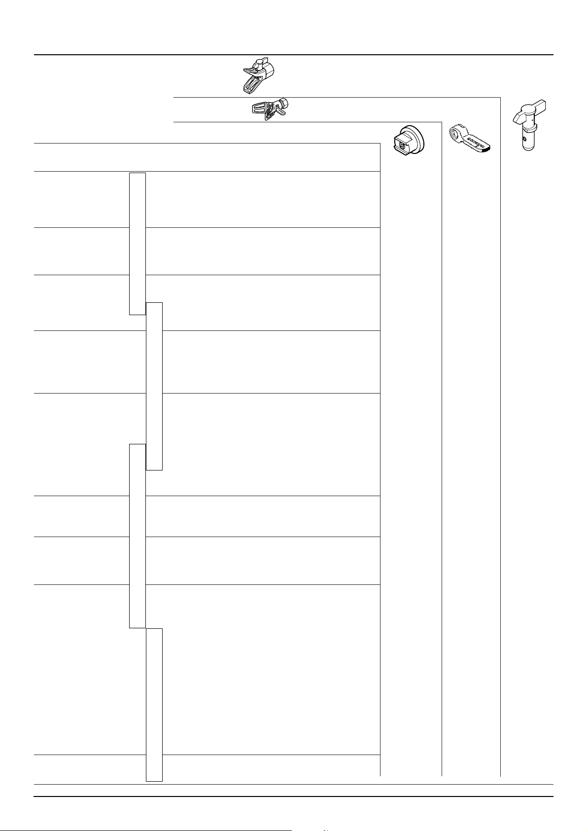
13.3 Spritzpistolen-Zubehör
Flachstrahl-Verstelldüse
bis 250 bar (25 MPa)
Page 26
Anwendung Düsen- Spritz- Bohrung Spritzbreite
markierung winkel inch / mm mm
1)
Bestell-Nr. Bestell-Nr. Bestell-Nr.
Naturlacke 407 40° 0.007 / 0.18 160 0090 407 1088 407 1006 407
farblose Lacke 507 50° 0.007 / 0.18 190 0090 507 ––––––– –––––––
Öle 209 20° 0.009 / 0.23 145 0090 209 1088 209 1006 209
309 30° 0.009 / 0.23 160 0090 309 1088 309 1006 309
409 40° 0.009 / 0.23 190 0090 409 1088 409 1006 409
509 50° 0.009 / 0.23 205 0090 509 1088 509 1006 509
609 60° 0.009 / 0.23 220 0090 609 1088 609 1006 609
Kunstharzlacke 111 10° 0.011 / 0.28 85 0090 111 1088 111 1006 111
PVC-Lacke 211 20° 0.011 / 0.28 95 0090 211 1088 211 1006 211
311 30° 0.011 / 0.28 125 0090 311 1088 311 1006 311
411 40° 0.011 / 0.28 195 0090 411 1088 411 1006 411
511 50° 0.011 / 0.28 215 0090 511 1088 511 1006 511
611 60° 0.011 / 0.28 265 0090 611 1088 611 1006 611
Lacke, Vorlacke 113 10° 0.013 / 0.33 100 0090 113 1088 113 1006 113
Zinkchromatgrund 213 20° 0.013 / 0.33 110 0090 213 1088 213 1006 213
Grundlacke 313 30° 0.013 / 0.33 135 0090 313 1088 313 1006 313
Füller 413 40° 0.013 / 0.33 200 0090 413 1088 413 1006 413
513 50° 0.013 / 0.33 245 0090 513 1088 513 1006 513
613 60° 0.013 / 0.33 275 0090 613 1088 613 1006 613
813 80° 0.013 / 0.33 305 0090 813 1088 813 1006 813
Füller 115 10° 0.015 / 0.38 90 0090 115 1088 115 1006 115
Spritzspachtel 215 20° 0.015 / 0.38 100 0090 215 1088 215 1006 215
Rostschutzfarben 315 30° 0.015 / 0.38 160 0090 315 1088 315 1006 315
415 40° 0.015 / 0.38 200 0090 415 1088 415 1006 415
515 50° 0.015 / 0.38 245 0090 515 1088 515 1006 515
615 60° 0.015 / 0.38 265 0090 615 1088 615 1006 615
715 70° 0.015 / 0.38 290 0090 715 1088 715 1006 715
815 80° 0.015 / 0.38 325 0090 815 1088 815 1006 815
Spritzspachtel 217 20° 0.017 / 0.43 110 0090 217 1088 217 1006 217
Rostschutzfarben 317 30° 0.017 / 0.43 150 0090 317 1088 317 1006 317
Mennige 417 40° 0.017 / 0.43 180 0090 417 1088 417 1006 417
Latexfarben 517 50° 0.017 / 0.43 225 0090 517 1088 517 1006 517
617 60° 0.017 / 0.43 280 0090 617 1088 617 1006 617
717 70° 0.017 / 0.43 325 0090 717 1088 717 1006 717
219 20° 0.019 / 0.48 145 0090 219 1088 219 1006 219
319 30° 0.019 / 0.48 160 0090 319 1088 319 1006 319
419 40° 0.019 / 0.48 185 0090 419 1088 419 1006 419
519 50° 0.019 / 0.48 260 0090 519 1088 519 1006 519
619 60° 0.019 / 0.48 295 0090 619 1088 619 1006 619
719 70° 0.019 / 0.48 320 0090 719 1088 719 1006 719
819 80° 0.019 / 0.48 400 0090 819 1088 819 1006 819
Glimmerfarben 221 20° 0.021 / 0.53 145 0090 221 1088 221 1006 221
Zinkstaubfarben 421 40° 0.021 / 0.53 190 0090 421 1088 421 1006 421
Dispersionen 521 50° 0.021 / 0.53 245 0090 521 1088 521 1006 521
621 60° 0.021 / 0.53 290 0090 621 1088 621 1006 621
821 80° 0.021 / 0.53 375 0090 821 1088 821 1006 821
Rostschutzfarben 223 20° 0.023 / 0.58 155 0090 223 1088 223 1006 223
423 40° 0.023 / 0.58 180 0090 423 1088 423 1006 423
523 50° 0.023 / 0.58 245 0090 523 1088 523 1006 523
623 60° 0.023 / 0.58 275 0090 623 1088 623 1006 623
723 70° 0.023 / 0.58 325 0090 723 1088 723 1006 723
823 80° 0.023 / 0.58 345 0090 823 1088 823 1006 823
Dispersionen 225 20° 0.025 / 0.64 130 0090 225 1088 225 1006 225
Binder-, Leim- 425 40° 0.025 / 0.64 190 0090 425 1088 425 1006 425
und Füllfarben 525 50° 0.025 / 0.64 230 0090 525 1088 525 1006 525
625 60° 0.025 / 0.64 250 0090 625 1088 625 1006 625
825 80° 0.025 / 0.64 295 0090 825 1088 825 1006 825
227 20° 0.027 / 0.69 160 0090 227 1088 227 1006 227
427 40° 0.027 / 0.69 180 0090 427 1088 427 1006 427
527 50° 0.027 / 0.69 200 0090 527 1088 527 1006 527
627 60° 0.027 / 0.69 265 0090 627 1088 627 1006 627
827 80° 0.027 / 0.69 340 0090 827 1088 827 1006 827
629 60° 0.029 / 0.75 285 0090 629 1088 629 1006 629
231 20° 0.031 / 0.79 155 0090 231 1088 231 1006 231
431 40° 0.031 / 0.79 185 0090 431 1088 431 1006 431
531 50° 0.031 / 0.79 220 0090 531 1088 531 1006 531
631 60° 0.031 / 0.79 270 0090 631 1088 631 1006 631
433 40° 0.033 / 0.83 220 0090 433 1088 433 1006 433
235 20° 0.035 / 0.90 160 0090 235 1088 235 1006 235
435 40° 0.035 / 0.90 195 0090 435 1088 435 1006 435
535 50° 0.035 / 0.90 235 0090 535 1088 535 1006 535
635 60° 0.035 / 0.90 295 0090 635 1088 635 1006 635
839 80° 0.039 / 0.99 480 0090 839 ––––––– –––––––
243 20° 0.043 / 1.10 185 0090 243 1088 243 1006 243
Großflächenanstriche 543 50° 0.043 / 1.10 340 0090 543 1088 543 1006 543
552 50° 0.052 / 1.30 350 0090 552 1088 552 1006 552
1)
Spritzbreite bei etwa 30 cm Abstand zum Spritzobjekt und 100 bar (10 MPa) Druck mit Kunstharzlack 20 DIN-Sekunden.
13.4 AirlessDüsen-Tabelle
Standarddüsen
bis 530 bar (53 MPa)
WAGNER Tip ohne Düse
bis 530 bar (53 MPa) Best.-Nr. 1088 001
WAGNER ohne Düse ohne Düse
Profi Tip F-Gewinde (11/16 - 16 UN) G-Gewinde (7/8 - 14 UNF)
bis 270 bar für Wagner Spritzpistolen für Graco/Titan Spritzpistolen
(27 MPa) Best.-Nr. 1006 001 Best.-Nr. 1006 002
Spritzpistolenfilter „GRÜN“
Spritzpistolenfilter „WEISS“
Spritzpistolenfilter „GELB“
Spritzpistolenfilter „ROT“
621
Anhang
d
24 ProSpray 23
621
Page 27

ProSpray 23 25
J. Wagner GmbH
Oberflächentechnik
Lohnergasse 1
1210 Wien
Oesterreich
Tel. (national) 0222/2707781-0
Tel. (international) 0043/1/2707781-0
Fax (national) 0222/2788430
Fax (international) 0043/1/2788430
Wagner Spraytech
Belgium SA
Veilinglaan 58
1861 Wolvertem-Meise
Belgien
Tel. 02/2694675
Telefax 02/2697845
J. Wagner AG
Industriestrasse 22
9450 Altstätten
Schweiz
Tel. 071 / 7 57 22 11
Telefax 071 / 7 57 22 22
Wagner Spraytech
Scandinavia A/S
Kornmarksvej 26
2605 Brøndby
Dänemark
Tel. 43632811
Telefax 43430528
Wagner Spraytech
Iberica S.A.
Apartado 132
08750 Molins de Rey
Barcelona / Spanien
Tel. 93/6800028
Telefax 93/6800555
J. Wagner France S.A.R.L
B.P. 75
91122 Palaiseau-Cedex
Frankreich
Tel. 01/60114050
Telefax 01/69817257
Wagner Spraytech (UK) Ltd.
Unit 3 Haslemere Way
Tramway Industrial Estate
Banbury, Oxon OX 16 8TY
England
Tel. 0 12 95 / 265 353
Telefax 0 12 95 / 269 861
Wagner Colora
Via Ciucani, 3
20060 Ornago (MI)
Italien
Tel. 039 / 6010474
Telefax 039 / 6010601
Wagner Spraytech
Nederland BV
Postbus 1656
3600 CA Maarssen
Niederlande
Tel. 030/2414155
Telefax 030/2411787
Wagner Sverige AB
Muskötgatan 19
254 66 Helsingborg
Schweden
Tel. 042 15 00 20
Telefax 042 15 00 35
Servicenetz in Deutschland
Europa-Servicenetz
D / 02 / 03
Hamburg
J. Wagner GmbH
Service-Stützpunkt Hamburg
Oehleckerring 9a - 13
22419 Hamburg
Tel. 040 / 5314010
Telefax 040 / 5324618
Hannover
J. Wagner GmbH
Service-Stützpunkt Hannover
Evered J. Poole
Schmiedestraße 7
30938 Burgwedel/Wettmar
Tel. 0 51 39 / 89 26 89
Telefax 0 51 39 / 8923 97
Mobil 0171 / 3519988
Bremen
J. Wagner GmbH
Handelsvertretung
H.W. Huss & Co
Stresemannstr. 54
28207 Bremen
Tel. 0421 / 443913
Telefax 0421 / 448336
Berlin
J. Wagner GmbH
Service-Stützpunkt Berlin
Flottenstraße 28–42
13407 Berlin
Tel. 0 30/ 41 10 93 88
Telefax 0 30 / 41 10 93 99
Leipzig
J. Wagner GmbH
Service-Stützpunkt Leipzig
Am Schenkberg 20
04349 Leipzig-Plaußig
Tel. 0 34 22 98 / 14 108-0
Telefax 0 34 22 98 / 14 108-40
a
b
g
i
n
s
Dresden
J. Wagner GmbH
Service-Stützpunkt Dresden
Joachim Walther
Neuhausener Straße 5
09548 Deutscheinsiedel
Tel. 03 73 62 / 82 63
Telefax 03 73 62 / 1 72 20
Münster
J. Wagner GmbH
Service-Stützpunkt Münster
Eulerstraße 11
48155 Münster
Tel. 02 51 / 60 89 60
Telefax 02 51 / 6 04 96
Ratingen
J. Wagner GmbH
Service-Stützpunkt Ratingen
Siemensstraße 6-10
40885 Ratingen
Tel. 0 21 02 / 3 10 37
Telefax 0 21 02 / 3 43 95
Kassel
J. Wagner GmbH
Service-Stützpunkt Kassel
Frank Genilke
Fliederweg 3
34305 Niedenstein
Tel. 0 56 24 / 92 55 37
Telefax 0 56 24 / 92 55 38
Mobil 0171 / 8248552
Mannheim
J. Wagner GmbH
Service-Stützpunkt Mannheim
Seckenheimer Straße 100
68532 Edingen-Neckarhausen
Tel. 0 62 03 / 20 34
Telefax 0 62 03 / 1 66 60
Trier
J. Wagner GmbH
Service-Stützpunkt Trier
Willi Schneider
Keltenstraße 2
54313 Zemmer-Rodt
Tel. 0 65 80 / 83 84
Telefax 0 65 80 / 13 01
Mobil 0171 / 6235650
Stuttgart
J. Wagner GmbH
Service-Stützpunkt Stuttgart
Alleenstraße 35
72666 Neckartailfingen
Tel 0 71 27 / 9 32 50
Telefax 0 71 27 / 2 25 26
Freiburg
J. Wagner GmbH
Service-Stützpunkt Freiburg
Bernhard Reichenstein
Tichstraße 7
79341 Kenzingen
Tel 0 76 44 / 74 71
Telefax 0 76 44 / 46 10
Mobil 0171 / 3618425
Rottweil
J. Wagner GmbH
Service-Stützpunkt Rottweil
Hans Mäntler
Hessensailstraße 21
78585 Bubsheim
Tel 0 74 29 / 91 03 14
Telefax 0 74 29 / 91 03 15
Mobil 0171 / 7265239
München
Jahnke GmbH
Hochstraße 7
82024 Taufkirchen
Tel 0 89 /6 14 00 22
Telefax 0 89 / 6 14 04 33
Niederbayern
Jahnke GmbH
Service-Stützpunkt Plattling
Herbert Raum
Bachstraße 30
94447 Plattling
Tel 0 99 31 / 56 44
Telefax 0 99 31 / 51 20
Mobil 0171 / 7773128
Nürnberg
J. Wagner GmbH
Handelsvertretung
Grimmer-Haseloff GmbH
Starenweg 28
91126 Schwabach
Tel 0 91 22 / 7 94 73
Telefax 0 91 22 / 79 47 50
Markdorf – Zentrale
J. Wagner GmbH
Otto-Lilienthal-Straße 18
88677 Markdorf
Postfach 11 20
88669 Markdorf
Tel 0 75 44 / 505-564
Telefax 0 75 44 / 505-167
email: Wagner@wagnergroup.com
www.wagner-group.com
c
x
e
f
Page 28

26 ProSpray 23
g
ProSpray 23
Warning!
Never put your fingers, hands or any other parts of the body into the
spray jet!
Never point the spray gun at yourself, other persons or animals.
Never use the spray gun without safety guard.
Do not treat a spraying injury as a harmless cut. In case of injury to
the skin through coating materials or solvents, consult a doctor
immediately for quick and expert treatment. Inform the doctor
about the coating material or solvent used.
The operating instructions state that the following points must
always be observed before starting up:
1. Faulty units must not be used.
2. Secure WAGNER spray gun using the safety catch on the
trigger.
3. Ensure that the unit is properly earthed. The connection
must take place through a correctly earthed two-pole and earth
socket outlet.
4. Check allowable operating pressure of high-pressure hose and
spray gun.
5. Check all connections for leaks.
The instructions regarding regular cleaning and maintenance of the
unit must be strictly observed.
Before any work is done on the unit or for every break in work the
following rules must be observed:
1. Release the pressure from spray gun and hose.
2. Secure the WAGNER spray gun using the safety catch
on the trigger.
3. Switch off unit.
①
②
③
Be safety-conscious!
Attention: Danger of injury by injection!
Airless units develop extremely high spraying pressures.
Danger
Danger
Page 29

Page
1. Safety regulations for Airless spraying...... 28
2. General view of application ........................ 30
2.1 Application .................................................... 30
2.2 Coating materials .......................................... 30
3. Description of unit ...................................... 30
3.1 Airless process .............................................. 30
3.2 Functioning of the unit .................................. 30
3.3 Legend for explanatory diagram
of unit on high carriage.................................. 31
3.4 Explanatory diagram of unit
on high carriage ............................................ 31
3.5 Legend for explanatory diagram of unit
on low carriage .............................................. 32
3.6 Explanatory diagram of unit
on low carriage .............................................. 32
3.7 Technical data................................................ 33
3.8 Transportation................................................ 33
3.9 Transportation in vehicle................................ 33
4. Starting operation........................................ 33
4.1 High-pressure hose, spray gun and
separating oil ................................................33/34
4.2 Illuminating display of electronic
pressure adjuster .......................................... 34
4.3 Pressure regulator knob settings .................. 35
4.4 Connection to the mains network.................. 35
4.5 Cleaning preserving agent when
starting-up of operation initially .................... 35
4.6 Taking the unit into operation
with coating material...................................... 36
5. Spraying technique...................................... 36
6. Handling the high-pressure hose .............. 36
6.1 High-pressure hose ...................................... 36
7. Interruption of work .................................... 36
8. Cleaning the unit (shutting down) .............. 37
8.1 Cleaning unit from outside ............................ 37
8.2 Suction filter .................................................. 37
8.3 Cleaning the high-pressure filter.................... 38
8.4 Cleaning Airless spray gun ............................ 38
Page
9. Remedy in case of faults ............................ 39
10. Servicing ...................................................... 41
10.1 General servicing .......................................... 41
10.2 High-pressure hose ...................................... 41
11. Repairs at the unit ...................................... 41
11.1 Relief valve .................................................... 41
11.2 Inlet and outlet valve......................................41/42
11.3 Packings ........................................................42/43
11.4 Carbon brushes in motor .............................. 43
11.5 ProSpray 23 connection diagram.................. 44
12. Accessories and spare parts...................... 45
12.1 Accessories for ProSpray 23 ........................ 45
Accessories illustration for ProSpray 23........ 104
12.2 Spare parts list for gear unit housing ............ 45
Spare parts diagram for gear unit housing.... 105
12.3 Spare parts list for color section.................... 46
Spare parts diagram for color section .......... 106
12.4 Spare parts list for motor .............................. 47
Spare parts diagram for motor ...................... 107
12.5 Spare parts list for high carriage.................... 47
Spare parts diagram for high carriage .......... 108
12.6 Spare parts list for low carriage .................... 48
Spare parts diagram for low carriage ............ 109
12.7 Spare parts list for suction system
of high carriage.............................................. 48
Spare parts diagram for suction system
of high carriage.............................................. 110
12.8 Spare parts list for suction system of
low carriage .................................................. 48
Spare parts diagram for suction system
of low carriage .............................................. 110
13. Appendix ...................................................... 49
13.1 Selection of tip ............................................ 49
13.2 Servicing and cleaning of Airless
hard-metal tips .............................................. 49
13.3 Spray gun accessories .................................. 49
13.4 Airless tip table ............................................ 50
Sales and service companies .............................. 51
Important notes on product liability .................... 111
Warranty.................................................................. 111
CE Declaration of conformity .............................. 113
ProSpray 23 27
g
Contents
Contents
Page 30

1. Safety regulations for Airless
spraying
All local regulations in force must be observed.
For secure handling of Airless high-pressure spraying
units the following safety regulations are to be observed:
Flash point
Only use coating materials with a flash
point of 21 °C or above without additional
heating.
The flash point is the lowest temperature
at which vapours develop from the coat-
ing material.
These vapours are sufficient to form an inflammable
mixture over the air above the coating material.
Explosion protection
Do not use the unit in work places which
are covered to the explosion protection
regulations.
Danger of explosion and fire through
sources of flame during spraying
work
There may be no sources of flame such as,
for example, open fires, smoking of ciga-
rettes, cigars or tobacco pipes, sparks,
glowing wires, hot surfaces, etc. in the vici-
nity.
Danger of injury through the spray jet
Caution! Danger of injury through injection!
Never point the spray gun at yourself, other persons
or animals.
Never use the spray gun without spray jet safety guard.
Danger
Danger
Danger
The spray jet may not come into contact with any
part of the body.
In working with Airless spray guns, the high spray
pressures arising can cause very dangerous injuries.
If contact is made with the spray jet, coating material
can be injected into the skin. Do not treat a spray injury as a harmless cut. In the case of injury to the
skin through coating material or solvents, consult a
doctor for quick and correct treatment. Inform the
doctor about the coating material or solvent used.
Secure spray gun against
unintended operation
Always secure the spray gun when mounting or dismounting the tip and in case of interruption to work.
Recoil of spray gun
In case of high operating pressure, pulling
the trigger can effect a recoil force of up to
15 N.
If you are not prepared for this, your hand
can be thrust backwards or your balance
lost. This can lead to injury.
Respiratory protection for protec-
tion against vapours of solvents
Wear respiratory protection when spraying.
The user must be provided with a breathing mask.
Prevention of occupational illnesses
Protective clothing, gloves and possibly skin protection
cream are necessary for the protection of the skin.
Observe the regulations of the manufacturer concerning
coating materials, solvents and cleaning agents in preparation, processing and cleaning units.
Max. operating pressure
Max. permissible operating pressure for spray gun,
spray gun accessories and high-pressure hose may
not fall short of the maximum operating pressure of
230 bar (23 MPa) stated on the unit.
High-pressure hose (safety note)
Electrostatic charging of spray guns and the high-pressure hose is discharged through the high-pressure hose.
For this reason the electric resistance between the
connections of the high-pressure hose must be equal or
lower than 1 MΩ.
i
Danger
28 ProSpray 23
g
Safety regulations
Danger
For reasons of function, safety and durability
use only original WAGNER high-pressure
hoses.
Page 31

Electrostatic charging (formation of
sparks or flame)
Under certain circumstances, electrostatic
charging can occur on the unit due to the ra-
te of flow of the coating material when
spraying. On discharging this can result in
the emergence of sparks or fire. It is therefore necessary that the unit is always earthed through the
electrical installation. The connection must take place
through a correctly earthed two-pole-and-earth socket
outlet.
Using unit on construction sites
Connection to the mains only through a special feed
point, e.g. through an error protection installation
with INF ≤ 30 mA.
Setting up the unit
When working indoors
Vapors containing solvents may not be allowed to
build up in the area of the device.
Setting up the unit on the side a way from
the sprayed object.
A minimum distance of 5 m between the
unit and spray gun is to be maintained.
When working outdoors
Vapors containing solvents may not be allowed to
blow toward the unit.
Note the direction of the wind.
Set the unit up in such a way that vapors
containing solvents do not reach the unit
and build up there.
A minimum distance of 5 m between the
unit and spray gun is to be maintained.
Ventilation when spraying in rooms
Adequate ventilation must be guaranteed for the removal
of the solvent vapours.
Suction installations
These are to be set-up by the user of the unit according
to local regulations.
Earthing of the object
The object to be coated must be earthed.
Cleaning units with solvents
When cleaning the unit with solvents, the sol-
vent should never be sprayed or pumped
back into a container with a small opening
(bunghole). An explosive gas/air mixture can
be produced. The container must be earthed.
Danger
Danger
Cleaning the unit
Danger of short circuit through penetrating water!
Never spray down the unit with high-pressure or high-pressure steam cleaners.
Work or repairs on the electrical
equipment
Only have this work carried out by a qualified electrician.
No liability will be taken for incorrect installation.
Working on electrical components
Remove the mains plug from the socket for all such
works.
Setting-up on uneven surfaces
The front side of the unit must point downwards to prevent sliding away.
Unit on high carriage
Danger
ProSpray 23 29
g
Safety regulations
Danger
Danger
Page 32

2. General view of application
2.1 Application
All painting jobs in the workshop and on the building
site, small dispersion work with the spray gun or internally fed Airless roller.
Examples of objects of spraying
Doors, door frames, balustrades, furniture, wooden cladding, fences radiators (heating) and steel parts, internal
ceilings and walls.
2.2 Coating materials
Processible coating materials
Dilutable lacquers and paints or those containing solvents, two-component coating materials, dispersions, latex paints.
No other materials should be used for spraying without
WAGNER’s approval.
Filtering
In spite of the suction filter, the insertion filter in the spray
gun and the high-pressure filter, filtering of the coating
material is to be recommended in general.
Stir coating material before commencement of work.
Viscosity
With this unit it is possible to process highly viscous
coating materials of up to around 25.000 mPa·s.
If highly viscous coating materials cannot be taken in by
suction, they must be diluted in accordance with the
manufacturer’s instructions.
Two-component coating material
The appropriate processing time must be adhered to
exactly. Within this time rinse through and clean the unit
meticulously with the appropriate cleaning materials.
Coating materials with sharp-edged additional
materials
These have a strong wear and tear effect on valves,
high-pressure hose, spray gun and tip. The durability of
these parts cane be reduced appreciably through this.
3. Description of unit
3.1 Airless process
The main areas of application are thick layers of highly
viscous coating material for large areas and a high consumption of material.
A piston pump takes in the coating material by suction
and conveys it to the tip. Pressed through the tip at a
pressure of up to a maximum of 230 bar (23 MPa), the
coating material is atomised. This high pressure has the
effect of micro fine atomisation of the coating material.
As no air is used in this process, it is described as an
AIRLESS process.
This method of spraying has the advantages of finest
atomisation, cloudless operation and a smooth, bubblefree surface. As well as these, the advantages of the
speed of work and convenience must be mentioned.
3.2 Functioning of the unit
In the following there is a short description of the technical construction for better understanding of the function.
WAGNER ProSpray units are electrically driven highpressure spraying units.
A gear unit transfers the driving force to a crankshaft.
The crankshaft moves the pistons of the material feed
pump up and down.
The inlet valve is opened automatically by the upwards
movement of the piston. The outlet valve is opened
when the piston moves downward.
The coating material flows under high pressure through
the high-pressure hose to the spray gun. When the coating material exits from the tip it atomizes.
The pressure regulator controls the volume and the operating pressure of the coating material.
30 ProSpray 23
g
General view of application Description of unit
Unit on low carriage
Pay attention to the Airless quality of the
coating materials to be processed.
Attention: Make sure, when stirring up with
motor-driven agitators that no air bubbles
are stirred in. Air bubbles disturb when
spraying and can, in fact, lead to interruption
of operation.
i
i
Page 33

ProSpray 23 31
g
Description of unit
3.3 Legend for explanatory diagram of unit on high carriage
1 Spray gun
2 High-pressure hose
3 Extendable handle
4 Unit connecting line
5 Relief valve
Lever position vertical – PRIME ( k circulation)
Lever position horizontal – SPRAY ( p)
6 Return hose
7 Filter
8 Suction tube
9 Manometer
10 Filling orifice for separating oil (separating oil prevents
increased wear of the packings)
11 Indicating light shows operational readiness
12 ON/OFF switch
13 Excess-current circuit breaker
14 Illuminating display of electronic pressure adjuster
15 High-pressure filter
16 Pressure regulator knob
1
3
4
78 56
9
10
11
2
16
1214 1315
3.4 Explanatory diagram of unit on high carriage
Page 34

32 ProSpray 23
g
Description of unit
6 Return hose
7 Filter
8 Suction hose
17 Cleaning agent container
3.5 Legend for explanatory diagram of unit on low carriage
3.6 Explanatory diagram of unit on low carriage
Non-positioned parts as with Figure 3.
Page 35

ProSpray 23 33
g
Description of unit Starting operation
3.7 Technical data ProSpray 23
Voltage: 230 V AC, 50 Hz
Max. current consumption: 5 A
Fuses: 16 A time-lag
Unit connecting line: 3 x 1.5 mm
2
– 6 m
Acceptance capacity: 1100 Watts
Max. operating pressure: 230 bar (23 MPa)
Volume flow at 120 bar
(12 MPa) with water: 2.1 l/min
Max. tip size: 0.023 inch – 0.58 mm
Max. temperature of the
coating material: 43°C
Max. viscosity: 25.000 mPa·s
Filter insert
(standard outfitting): mesh 60
Weight: 25 kg
Special high-pressure hose: DN 6 mm, 15 m connecting
thread M 16 x 1.5
Dimensions (L x W x H)
Unit on high carriage: 580 x 565 x 760 mm
Unit on low carriage: 820 x 430 x 545 mm
Max. sound pressure level: 80 dB (A) *
* Place of measuring: 1 m in distance from the unit and 1.6
m above the floor, 120 bar (12 MPa) operating pressure,
reverberant floor.
3.8 Transportation
Pushing or pulling the unit
Pull out the handle (Fig. 5, Item 1) until it will come no
further. Insert the handle – push the buttons (2) on the
spars, and then push in the handle.
1
2
2
5
3
1
2
4
3.9 Transportation in vehicle
Roll the high-pressure hose over the suspension device
at the handle.
Secure the unit with a suitable fastening.
4. Starting operation
4.1 High-pressure hose, spray gun and
separating oil
1. Screw the manometer combination (2) at the coating
material outlet (Fig. 6, Item 1).
2. Screw the transition socket (3) to the manometer
combination.
3. Screw the high-pressure hose (4) to the manometer
combination.
4. Screw the spray gun (5) with the selected tip onto the
high-pressure hose.
5. Tighten the union nuts at the high-pressure hoses
firmly so that coating material does not leak.
Page 36

34 ProSpray 23
g
Starting operation
Attention
Separating oil prevents increased
wear and tear to the packings.
6.
7. Fill in separating oil (Fig. 7). Do not fill in too much separating oil, i.e. ensure that no separating oil drips into the coating material container.
SERVICE
1
2
3
4.2 Illuminating display of electronic
pressure adjuster
1. Flashing yellow – no pressure generation
2. Yellow – up to 120 bar (12 MPa)
3. Green – from 120 bar (12 MPa) to 230 bar (23 MPa)
Page 37

ProSpray 23 35
g
Starting operation
1
2
3
4
5
6
7
8
9
4
3
2
1
4
2
5
3
1
4.3 Pressure regulator knob settings
(Fig. 9)
1. Minimum pressure setting
2. From minimum pressure to 230 bar (23 MPa)
3. Black zone – no pressure generation
4. Blue zone – pulsating pressure for cleaning
4.4 Connection to the mains network
Before connecting the unit to the mains supply, ensure
that the line voltage matches that specified on the unit’s
rating plate.
As soon as the power plug is connected, the green indicating lamp under the ON/OFF switch illuminates.
Attention
The unit must be connected to an
appropriately-grounded safety outlet.
4.5 Cleaning preserving agent when
starting-up of operation initially
1. Depending on the model, swivel or immerse the suc-
tion tube (Fig. 10, Item 1) or the suction hose and return hose (2) into a container with a suitable cleaning
agent.
2. Turn the pressure regulator knob (3) in the yellow zo-
ne to minimum pressure.
3. Open the relief valve (4), valve position PRIME
(k circulation).
4. Switch the unit (5) ON.
5. Wait until the cleaning agent exudes from the return
hose.
6. Close the relief valve, valve position SPRAY
(p spray).
7. Pull the trigger of the spray gun.
8. Spray the cleaning agent from the unit into an open
collecting container.
Page 38

36 ProSpray 23
g
Starting operation Interruption of work
4.6. Taking the unit into operation with
coating material
1. Depending on the model swivel or immerse the suc-
tion tube (Fig. 10, Item 1) or the suction hose and return hose (2) into the coating material container.
2. Turn the pressure regulator knob (3) in the yellow zo-
ne to minimum pressure.
3. Open the relief valve (4), valve position PRIME
(k circulation).
4. Switch the unit (5) ON.
5. Wait until the coating material exudes from the return
hose.
6. Close the relief valve, valve position SPRAY
(p spray).
7. Trigger the spray gun several times and spray into a
collecting container until the coating material exits the
spray gun without interruption.
8. Increase the pressure by slowly turning up the pres-
sure regulator knob.
Check the spray pattern and increase the pressure
until the atomization is correct.
Always turn the pressure regulator knob to the lowest
setting with good atomization.
9. The unit is ready to spray.
5. Spraying technique
Move the spray gun evenly during the spraying process.
Otherwise the spray pattern will be uneven. Carry out the
spray movement with the arm, not with the wrist. Observe a parallel distance of approx. 30 cm between the
spray gun and the object of spraying. The lateral edge of
the spray jet should not be too distinct. The spray edge
should be gradual in order to facilitate overlapping of the
next coat. Always move the spray gun parallel and at an
angle of 90° to the surface to be coated in order to minimize the paint mist.
6. Handling the high-pressure
hose
Avoid sharp bending or kinking of the high-pressure hose. The smallest bending radius amounts to about 20 cm.
Do not drive over the high-pressure hose. Protect
against sharp objects and edges.
6.1 High-pressure hose
The unit is equipped with a high-pressure hose specially
suited for piston pumps.
7. Interruption of work
1. Open the relief valve, valve position PRIME
(k circulation).
2. Switch the unit OFF.
3. Turn the pressure regulator knob into the black zone
until it stops (no pressure generation).
4. Pull the trigger of the spray gun in order to release the
pressure from the high-pressure hose and spray gun.
5. Secure the spray gun, refer to the operating manual
of the spray gun.
6. If a standard tip is to be cleaned, see Page 49, Sec-
tion 13.2.
If a non-standard tip is installed, proceed according
to the relevant operating manual.
7. Depending on the model, leave the suction tube or
the suction hose and return hose immersed in the
coating material or swivel or immerse it into a corresponding cleaning agent.
If very sharp edges result or if there are streaks in the spray jet – increase the operating
pressure or dilute the coating material.
i
Danger of injury through leaking highpressure hose. Replace any damaged
high-pressure hose immediately.
Never repair defective high-pressure
hoses yourself!
Only use WAGNER original-high-pressure
hoses in order to ensure functionality, safety
and durability.
i
Danger
Attention
If fast-drying or two-component coating material is used, ensure that the
unit is rinsed with a suitable cleaning
agent within the processing time.
Page 39

ProSpray 23 37
g
Cleaning the unit (shutting down)
8. Cleaning the unit
(shutting down)
A clean state is the best method of ensuring operation
without problems. After you have finished spraying, clean the unit. Under no circumstances may any remaining
coating material dry and harden in the unit.
The cleaning agent used for cleaning (only with an ignition point above 21 °C) must be suitable for the coating
material used.
• Secure the spray gun, refer to the operating manual
of the spray gun.
Clean and remove tip.
For a standard tip, refer to Page 49, Section 13.2.
If a non-standard tip is installed, proceed according to
the relevant operating manual.
1. Depending on the model, swivel out or remove the
suction tube or the suction hose and return hose
from the coating material.
2. Close the relief valve, valve position
SPRAY (p spray).
3. Switch the unit ON.
4. Pull the trigger of the spray gun in order to pump the
remaining coating material from the suction tube or
suction hose, high-pressure hose and the spray gun
into an open container.
8.1 Cleaning unit from outside
Wipe down unit externally with a cloth which has been
immersed in a suitable cleaning agent.
8.2 Suction filter
– Screw off the filter (fig. 11) from suction pipe.
– Clean or replace the filter.
Carry out cleaning with a hard brush and an appropriate cleaning agent.
5. Depending on the model, swivel or immerse the suc-
tion tube or suction hose with the return hose into a
container with cleaning agent.
6. Turn the pressure regulator knob into the blue zone -
pulsating pressure for unit cleaning.
7. Open the relief valve, valve position PRIME (k circu-
lation).
8. Pump a suitable cleaning agent in the circuit for a
few minutes.
9. Close the relief valve, valve position
SPRAY (p spray).
10. Pull the trigger of the spray gun.
11. Pump the remaining cleaning agent into an open
container until the unit is empty.
12. Switch the unit OFF.
The container must be earthed in case of
coating materials which contain solvents.
Attention
Caution! Do not pump or spray into a
container with a small opening (bunghole)!
Refer to the safety regulations.
Danger
First of all pull out mains plug from
socket.
Danger
Danger of short circult through panetrating water!
Never spray down the unit with
high-pressure or high-pressure steam
cleaners.
Danger
A clean suction filter always guarantees
maximum feed quantity, constant spraying
pressure and problem-free functioning
of the unit.
i
Page 40

8.3 Cleaning the high-pressure filter
Clean the filter cartridge regularly.
A soiled or clogged high-pressure filter can cause a poor
spray pattern or a clogged tip.
1. Turn the pressure regulator knob into the black zone
until it stops (no pressure).
2. Open the relief valve, valve position PRIME
(k circulation).
3. Switch the unit OFF.
4. Unscrew the filter housing (Fig. 12, Item 1). with a
strap wrench.
5. Pull the filter cartridge (2) from the bearing spring (3).
6. Clean all the parts with the corresponding cleaning
agent. If necessary, replace the filter cartridge.
7. Check the O-ring (4), replace it if necessary.
8. Place the bearing ring (5) against the bearing spring
(3). Slide the filter cartridge (2) over the bearing
spring.
9. Screw in the filter housing (1) and tighten it as far as
possible with the strap wrench.
38 ProSpray 23
g
Cleaning the unit (shutting down)
8.4 Cleaning Airless spray gun
– Rinse Airless spray gun with an appropriate clea-
ning agent.
– Clean tip thoroughly with appropriate cleaning
agent so that no coating material residue remains.
– Thoroughly clean the outside of the Airless spray
gun.
Intake filter in Airless spray gun
Dismounting (fig. 13)
1. Pull protective guard (1) forward vigorously.
2. Screw grip (2) out of the gun housing. Remove
intake filter (3).
3. Intake filter congested or defective – replace.
Mounting
1. Place intake filter (3) with the long cone into the gun
housing.
2. Screw in grip (2) into the gun housing and tighten.
3. Slot in protective guard (1).
4
3
5
2
1
3
Warning:
keep clear
of tip
250 bar
max.3600 psi
2
1
Unplug the power plug from the outlet.
Danger
Page 41

ProSpray 23 39
g
Remedy in case of faults
9. Remedy in case of faults
Unit does not start
Unit does not suck in
Unit sucks, but the
pressure does not
build up
Check light does not indicate
operational readiness.
No voltage applied.
The unit switches off automatically if an overload occurs.
The unit does not switch on
again automatically.
Pressure setting too low.
ON/OFF switch defective.
Carbon brushes in motor are
used up.
Relief valve is set to SPRAY
(pspray).
Filter projects over the fluid
level and sucks air.
Filter clogged.
Unit on high carriage
Suction tube is loose, i.e. the
unit is sucking in outside air.
Unit on low carriage
Suction hose is loose, i.e. the
unit is sucking in outside air.
Tip heavily worn.
Top too large.
Pressure setting too low.
Filter clogged.
Coating material flows
through the return hose when
the relief valve is in the SPRAY
(pspray) position.
Packings sticky or worn.
Valve balls worn.
Valve seats worn.
Check voltage supply.
Switch the unit OFF. Press the excess-current circuit
breaker after 2 – 3 minutes and switch unit ON again.
Turn up pressure regulator knob.
Replace
Replace
Set relief valve to PRIME (k circulation).
Refill the coating material.
Clean or replace the filter.
Clean connecting points. Tighten suction tube.
Clean connecting points. Replace O-rings if
necessary. Secure suction hose with retaining clip.
Replace
For selection of a smaller tip, see Tip table on
Page 50.
Turn pressure regulator knob to a higher number.
Clean or replace the filter.
Remove and clean or replace relief valve.
Remove and clean or replace packings.
Remove and replace valve balls.
Remove and replace valve seats.
Type of malfunction Possible cause Measures for eliminating the malfunction
Page 42

40 ProSpray 23
g
Remedy in case of faults
Coating material exits
at the top of the paint
section
Increased pulsation at
the spray gun
Poor spray pattern
Unit loses power
Upper packing is worn.
Piston is worn.
Incorrect high-pressure hose
type.
Tip worn or too large.
Pressure too high.
Tip is too large for the coating
material which is to be sprayed.
Pressure setting incorrect.
Volume too low.
Coating material viscosity
too high.
Pressure setting too low.
Remove and replace packing.
Remove and replace piston.
Only use WAGNER original-high-pressure hoses
in order to ensure functionality, safety and durability.
Replace tip.
Turn pressure regulator knob to a lower number.
Replace tip, see Tip table on Page 50.
Turn pressure regulator knob until a satisfactory
spraying pattern is achieved.
Clean or replace all filters.
Thin out according to the manufacturer’s instructions.
Turn pressure regulator knob to a higher number.
Type of malfunction Possible cause Measures for eliminating the malfunction
Page 43

ProSpray 23 41
g
Servicing Repairs at the unit
10. Servicing
10.1 General servicing
Servicing of the unit should be carried out once
annually by the WAGNER service.
1. Check high-pressure hoses, device connecting
line and plug for damage.
2. Check the inlet valve, outlet valve and filter for
wear.
10.2 High-pressure hose
Inspect the high-pressure hose visually for any notches
or bulges, in particular at the transition in the fittings. It
must be possible to turn the union nuts freely.
11. Repairs at the unit
11.1 Relief valve
1. Use a drift punch of 2 mm to remove the grooved pin
(Fig. 14, Item 1) from the relief valve grip (2).
2. Pull of the relief valve grip (2) and drive ring (3).
3. Screw off the valve housing (4) completely using the
adjusting spanner.
4. Ensure that the seal (5) is seated correctly, then screw
the new valve housing (4) completely into the paint
section housing (6). Tighten using the adjusting spanner.
5. Align the drive ring (3) to the hole in the paint section
housing (6). Slide the drive ring on and lubricate with
machine grease.
6. Bring the hole in the valve shaft (7) and in the relief
valve grip (2) into alignment.
7. Insert the grooved pin (1) and set the relief valve grip
to the position PRIME/SPRAY.
11.2 Inlet and outlet valve
1. Remove the four screws in the front cover and then
the front cover.
2. Switch the unit ON and then OFF so that the connecting rod is positioned in the lower stroke position.
3.
4. Unit on high car
riage
Screw off the suction tube.
Unit on low car
riage
Remove the retaining clip from the connecting bend
at the suction hose and pull off the suction hose.
5. Screw off the return hose.
6. Swivel the unit 90° to the rear in order to work more
easily on the material feed pump.
7. Unscrew inlet valve housing (Fig. 15, Item 1) from the
paint section housing.
8. Remove the lower seal (2), lower ball guide (3), inlet
valve ball (4), inlet valve seat (5) and O-ring (6).
9. Clean all the parts with the corresponding cleaning
agent.
Check the inlet valve housing (1), inlet valve seat (5)
and inlet valve ball (4) for wear and replace the parts
if necessary. If the worn inlet valve seat (5) is unused
on one side, install it the other way round.
Danger
Switch the unit OFF.
Before all repair work: Unplug the
power plug from the outlet.
Danger
Danger of crushing - do not reach with
the fingers or tool between the moving
parts.
Danger
Unplug the power plug from the outlet.
6
5
7
3
2
1
4
2
3
4
5
6
1
Page 44

42 ProSpray 23
g
Repairs at the unit
10. Unscrew outlet valve housing (Fig. 16, Item 7) from
the piston (8) with adjusting wrench.
11. Remove the upper seal (9), upper ball guide (10), outlet valve ball (11), outlet valve seat (12) and O-ring
(13).
12. Clean all the parts with the corresponding cleaning
agent. Check outlet valve housing (7), outlet valve
seat (12), outlet valve ball (11) and upper ball guide
(10) for wear and replace parts if necessary. If the
worn outlet valve seat (12) is unused on one side, install it the other way round.
13. Carry out installation in the reverse order. Lubricate
O-ring (Fig. 15, Item 6) with machine grease and ensure proper seating in the inlet valve housing (Fig. 15,
Item 1).
8
9
10
11
12
13
7
5
6
7
8
1
2
4
10
9
3
11.3 Packings
1. Remove inlet valve housing in accordance with the
steps in Chapter 11.2, Page 41.
2. It is not necessary to remove the outlet valve.
3. Unscrew both cylinder head screws (Fig. 17, Item 1)
from the paint section housing (2) with a 3/8 inch hexagon socket head wrench.
4. Pull paint section housing (2) approx 15 mm off of
gear unit housing.
5. Pull paint section housing (2) toward the front with
piston (3) until the piston is free from the T-slot (4) of
the connecting rod (5).
6. Push piston (3) downward out of the paint section
housing (2).
7. Unscrew guide nut (6) from the paint section housing
(2) and remove piston guide (7).
8. Remove upper packing (8) and lower packings (9)
from the paint section housing (2).
Page 45

ProSpray 23 43
g
Repairs at the unit
1
2
1
2
5
2
3
4
7
6
1
9. Clean paint section housing (2).
10. Lubricate upper packing (8) and lower packings (9)
with machine grease.
11. Insert upper packing (Fig. 18) with O-ring (1) and
protruding lip (2) downward.
12. Insert lower packings (Fig. 19) with O-ring (1) and
protruding lip (2) upward.
13. Insert piston guide (Fig. 17, Item 7) into the guide nut
(6). Screw guide nut (6) into the paint section housing
(2) and tighten by hand.
14. Push installation tool (in scope of delivery of replacement packings) for the piston (3) from above onto the
piston.
15. Lubricate installation tool and piston (3) with machine
grease.
16. Guide piston (3) through the lower packings (9) into
the paint section housing (2) from below. Using a
rubber mallet, lightly tap the piston (3) from below
until it can be seen above the paint section housing.
17. Remove installation tool from piston (3).
18. Carefully tighten guide nut (6) with adjusting wrench.
19. Insert upper end of the piston (3) into the T-slot (4) of
the connecting rod (5).
20. Attach paint section housing (2) to the gear unit housing. Ensure that the pressure sensor does not damage the pressure sensor seal (10).
21 Screw paint section housing (2) tightly to gear unit
housing.
22. Lubricate O-ring (Fig. 15, Item 6) between paint section housing (2) and inlet valve housing with machine
grease. Screw inlet valve housing to the paint section
housing.
23. Unit on high car
riage
Screw on suction tube. Screw on return tube and
clamp to suction tube.
Unit on low car
riage
Push connection bend of suction hose into the inlet
valve housing (Fig. 15, Item 1) and secure with retaining clip. Screw on return hose and clamp to suction
hose.
24. Install front cover.
11.4 Carbon brushes in motor
1. Remove the four screws (Fig. 20, Item 1) at the motor
cover (2). Remove motor cover.
2. Remove the two screws (3) at the shells (4). Remove
shells.
3. Lift up both covers (5) with a small screwdriver.
4. Pull red wire (6) and black wire (7) out of the
respective carbon brush.
5. Insert new carbon brush and snap cover (5) into
place.
6. Insert red wire (6) and black wire (7) onto the
respective carbon brush.
7. Screw down both shells (4).
8. Push motor cover (2) over the motor and fasten with
the four screws (1).
Page 46

44 ProSpray 23
g
Repairs at the unit
11.5 ProSpray 23 connection diagram
Motor
black
black
Capacitors
black
red
red
red
red
whitewhite
black
Recti-
fier
Power plug
Pressure sensor
Earthing
blue
green
green
green
Operation
indicator
brown
blue
Switch
blue
green yellow
Input
brown
brown
Output
Inter-
ference
sup-
pressor
filter
Potentiometer
Excess-current
circuit breaker
Electronic
controller
Earthing
white
black
Motor
TP5
TP4
JP1 JP3 TP3
TP2
TP1
Neutral
Motor
Switch
black
black
Page 47

Item Order No. Description
4 9984 510 High-pressure hose DN 4 mm, 7.5 m
with stainless steel nipple
9984 507 High-pressure hose DN 6 mm, 15 m
for dispersion
9984 562 High-pressure hose DN 6 mm, 30 m
for dispersion
5 0034 030 Double socket for coupling high-pressure
hoses
6 0034 950 Metex-Reuse
Reuse for pre-filtering of coating material
in vessel.
Place suction pipe in the reuse.
0034 952 Sieve package (5 pcs) for paint
0034 951 Sieve package (5 pcs) for dispersion
ProSpray 23 45
g
Accessories and spare parts
12. Accessories and spare parts
12.1 Accessories for ProSpray 23
(accessories illustration, see Page 104)
Item Order No. Description
1 0149 040 Spray gun G 08
(aluminium model)
0335 002 Spray gun G 12
(aluminium model)
0257 001 Spray gun AG-09 S
(stainless steel model)
2 0096 004 Pole gun 30 cm
0096 019 Pole gun 100 cm
0096 005 Pole gun 150 cm
0096 006 Pule gun 270 cm
3 0345 010 In-line roller IR-100
12.2 Spare parts list for gear unit housing
(spare parts diagram, see Page 105)
Item Order No. Description
1 0508 571 Screw
2 0508 570 Front cover
3 –––––––– Indicating light
4 9850 936 ON/OFF switch (230 V AC, 50 Hz)
5 0508 572 Crankshaft
6 0508 573 Thrust ring
7 0507 938 Gearwheel, Stage 2
8 0508 200 Gear unit housing
9 0508 208 Connecting rod
10 0507 748 Sealing cap
14 0507 749 Nut
15 0507 740 Pressure regulator knob
16 0508 575 Disc for potentiometer
18 0507 973 Potentiometer
19 0508 580 Excess-current circuit breaker
Item Order No. Description
20 0508 581 Screw
23 0508 643 Capacitor-rectifier set
(230 V AC, 50 Hz) with item 24
24 9802 244 Screw
25 0508 656 Electronic pressure adjuster
(with item 28, 29, 30)
28 0508 621 Cover, LED
29 0508 657 Screw
30 0507 751 Sealing cap
31 0508 658 Interference suppressor module
33 0508 654 Pressure sensor
34 9850 644 Cable threaded joint
35 9800 340 Screw
36 0261 352 Unit connecting line
H07RN-F3 G 1.5 – 6 m
Page 48

46 ProSpray 23
g
Accessories and spare parts
Item Order No. Description
1 0034 041
2 0340 256
3 3505 045
4 0508 689
5 0507 517
6 0508 666*
7 0508 665*
8 0508 664
10 0508 604
11 0508 749
12 0508 603
13 0508 449
0508 748
0508 450
14 0508 602
15 0508 601
18 0508 212
19 0507 745
20 0508 683
21 0508 744
22 0508 745
23 0508 684
27 0508 690
0508 680
28 3500 203*
29 0508 679
30 0508 678*
31 0508 677
32 0508 739*
33 0508 676
34 0508 211
35 0508 675
36 0508 674*
37 0508 673
38 0508 672*
39 0508 671
40 0508 670*
41 0508 669
42 0508 668*
43 0508 553
0508 214*
0508 619
0508 620
9984 507
12.3 Spare parts list for color section
(spare parts diagram, see Page 106)
Transition socket M 16 x 1.5
Manometer combination
Double socket
Paint section housing
Sealing stopper
Upper packing
Piston guide
Guide nut
O-ring
Bearing spring
Bearing ring
Filter cartridge, 30 meshes
Filter cartridge, 60 meshes (standard equipment)
Filter cartridge, 100 meshes
Conical spring
Filter housing
Relief valve
Seal
Drive ring
Relief valve grip
Grooved pin
Double nipple
Inlet valve housing (unit with high carriage)
Inlet valve housing (unit with low carriage)
O-ring
Inlet valve seat
Inlet valve ball
Lower ball guide
Lower seal
Bushing
Piston (Item 35 -> 41)
Outlet valve housing
O-ring
Outlet valve seat
Outlet valve ball
Upper ball guide
Upper seal
Piston
Lower packing (2)
Cylinder head screw (2)
Service set packings with machine grease
and installation tool
118 ml separating oil (prevents increased wear
and tear to the packings)
118 ml cleaner (for the color section interior)
High-pressure hose DN 6 mm, 15 m
Page 49

ProSpray 23 47
g
Accessories and spare parts
12.4 Spare parts list for motor
(spare parts diagram, see Page 107)
Item Order No. Description
1 0508 643
2 0508 559
3 0508 644
4 0508 645
5 0508 646
6 9802 891
7 0508 562
8 0508 648
9 0508 649
13 0508 563
14 0508 564
15 0508 688
16 0508 650
17 0508 215
12.5 Spare parts list for high carriage
(spare parts diagram, see Page 108)
Item Order No. Description
1 0508 583
2 9841 504
3 0295 607
4 0295 609
5 0295 610
6 0295 608
7 0295 606
8 0507 956
9 0294 534
10 9890 104
11 0508 584
12 0295 617
13 0278 373
14 0508 586
15 0508 555
Capacitor-rectifier set (230 V AC, 50 Hz)
Cylinder head screw (4)
Stranded wires (black)
Carbon brush set
Shell
Screw (2)
Seal
Ventilator
Screw
Screw (4)
Rubber socket
Motor cover
Stranded wires (red)
Motor (230 V AC, 50 Hz)
Handle
Retaining spring
Guide bush
Washer
Clamping sleeve
Screw
Washer
Clamping sleeve
Washer
Hub cap
Base frame
Sealing stopper
Wheel
Sealing stopper
Hexagonal bolt
Page 50

48 ProSpray 23
g
Accessories and spare parts
Item Order No. Description
1 0507 956
2 0294 534
3 0270 394
4 9890 104
5 0508 589
6 0295 617
10 0295 615
11 0507 955
12 0508 591
13 9841 504
Item Order No. Description
14 0295 607
15 0295 609
16 0295 610
17 0295 606
18 0295 608
19 0508 590
20 0508 381
21 0295 618
22 0508 588
24 9885 546
12.6 Spare parts list for low carriage
(spare parts diagram, see Page 109)
Item Order No. Description
1 0508 692
2 0508 747
3 0508 556
4 0507 783
12.7 Spare parts list for suction system of high carriage
(spare parts diagram, see Page 110)
Item Order No. Description
1 0508 605
2 9871 105
3 9822 526
4 0508 608
5 0507 937
6 0508 738
12.8 Spare parts list for suction system of low carriage
(spare parts diagram, see Page 110)
Clamping sleeve
Washer
Wheel
Hub cap
Base frame
Sealing stopper
Hexagonal nut
Screw
Handle
Retaining spring
Suction tube
Filter, 10 meshes
Return hose
Clamp
Guide bush
Washer
Clamping sleeve
Washer
Screw
Hexagonal bolt
Cleaning agent container
Screw
Mounting bracket
Sealing stopper
Return hose
O-ring (2)
Retaining clip
Suction hose
Clamp
Filter
Page 51

ProSpray 23 49
g
Appendix
Bore Spray width at about 30 cm Flat jet
Tip marking mm removal of spray object Use adjusting tip
Pressure 100 bar (10 MPa) Order no.
15 0.13 - 0.46 5 - 35 cm Paints 0999 057
20 0.18 - 0.48 5 - 50 cm Paints, fillers 0999 053
28 0.28 - 0.66 8 - 55 cm Paints, dispersions 0999 054
41 0.43 - 0.88 10 - 60 cm Rust protection
paints - dispersions 0999 055
49 0.53 - 1.37 10 - 40 cm Large-area coats 0999 056
Contact protection
for the flat jet adjustment tip
Order no. 0097 294
Tip extension with
slewable knee joint
(without tip)
Length 100 cm Order no. 0096 015
Length 200 cm Order no. 0096 016
Length 300 cm Order no. 0096 017
Tip extension
Length 15 cm Order no. 0999 320
Length 30 cm Order no. 0999 321
Length 45 cm Order no. 0999 322
Length 60 cm Order no. 0999 323
13. Appendix
13.1 Selection of tip
To achieve faultless and rational working, the selection of the tip is of the greatest importance.
In many cases the correct tip can only be determined by means of a spraying test.
Some rules for this:
The spray jet must be even.
If streaks appear in the spray jet the spraying pressure is either too low or the viscosity of the coating material to high.
Remedy: Increase pressure or dilute coating material. Each pump conveys a certain quantity in proportion to the size
of the tip:
The following principle is valid: large tip = low pressure
small tip = high pressure
There is a large range of tips with various spraying angles.
13.2 Servicing and cleaning of Airless hard-metal tips
Standard tips
If a different tip type has been fitted, then clean it according to manufacturer’s instructions.
The tip has a bore processed with the greatest precision. Careful handling is necessary to achieve long durability.
Do not forget the fact that the hard-metal insert is brittle! Never throw the tip or handle with sharp metal objects.
The following points must be observed to keep the tip clean and ready for use:
1. Open the relief valve, valve position PRIME (kcirculation).
2. Switch off unit.
3. Dismount the tip from the spray gun.
4. Place tip in an appropriate cleaning agent until all coating material residue is dissolved.
5. If there is pressure air, blow out tip.
6. Remove any residue by means of a sharp wooden rod (toothpick).
7. Check the tip with the help of a magnifying glass and, if necessary, repeat points 4 to 6.
13.3 Spray gun accessories
Flat jet adjusting tip
up to 250 bar (25 MPa)
Page 52

50 ProSpray 23
Application Tip Spray Bore Spraying
marking angle inch / mm width mm
1)
Order no. Order no. Order no.
Natural paints 407 40° 0.007 / 0.18 160 0090 407 1088 407 1006 407
Clear paints 507 50° 0.007 / 0.18 190 0090 507 ––––––– –––––––
Oils 209 20° 0.009 / 0.23 145 0090 209 1088 209 1006 209
309 30° 0.009 / 0.23 160 0090 309 1088 309 1006 309
409 40° 0.009 / 0.23 190 0090 409 1088 409 1006 409
509 50° 0.009 / 0.23 205 0090 509 1088 509 1006 509
609 60° 0.009 / 0.23 220 0090 609 1088 609 1006 609
Synthetic-resin paints 111 10° 0.011 / 0.28 85 0090 111 1088 111 1006 111
PVC paints 211 20° 0.011 / 0.28 95 0090 211 1088 211 1006 211
311 30° 0.011 / 0.28 125 0090 311 1088 311 1006 311
411 40° 0.011 / 0.28 195 0090 411 1088 411 1006 411
511 50° 0.011 / 0.28 215 0090 511 1088 511 1006 511
611 60° 0.011 / 0.28 265 0090 611 1088 611 1006 611
Paints, primers 113 10 ° 0.013 / 0.33 100 0090 113 1088 113 1006 113
Zinc chromate base 213 20° 0.013 / 0.33 110 0090 213 1088 213 1006 213
Fillers 313 30° 0.013 / 0.33 135 0090 313 1088 313 1006 313
413 40° 0.013 / 0.33 200 0090 413 1088 413 1006 413
513 50° 0.013 / 0.33 245 0090 513 1088 513 1006 513
613 60° 0.013 / 0.33 275 0090 613 1088 613 1006 613
813 80° 0.013 / 0.33 305 0090 813 1088 813 1006 813
Fillers 115 1 0° 0.015 / 0.38 90 0090 115 1088 115 1006 115
Spray plasters 215 20° 0.015 / 0.38 100 0090 215 1088 215 1006 215
Rust protection paints 315 30° 0.015 / 0.38 160 0090 315 1088 315 1006 315
415 40° 0.015 / 0.38 200 0090 415 1088 415 1006 415
515 50° 0.015 / 0.38 245 0090 515 1088 515 1006 515
615 60° 0.015 / 0.38 265 0090 615 1088 615 1006 615
715 70° 0.015 / 0.38 290 0090 715 1088 715 1006 715
815 80° 0.015 / 0.38 325 0090 815 1088 815 1006 815
Spray plasters 217 20° 0.017 / 0.43 110 0090 217 1088 217 1006 217
Rust protection paints 317 30° 0.017 / 0.43 150 0090 317 1088 317 1006 317
Red lead 417 40° 0.017 / 0.43 180 0090 417 1088 417 1006 417
Latex paints 517 50° 0.017 / 0.43 225 0090 517 1088 517 1006 517
617 60° 0.017 / 0.43 280 0090 617 1088 617 1006 617
717 70° 0.017 / 0.43 325 0090 717 1088 717 1006 717
219 20° 0.019 / 0.48 145 0090 219 1088 219 1006 219
319 30° 0.019 / 0.48 160 0090 319 1088 319 1006 319
419 40° 0.019 / 0.48 185 0090 419 1088 419 1006 419
519 50° 0.019 / 0.48 260 0090 519 1088 519 1006 519
619 60° 0.019 / 0.48 295 0090 619 1088 619 1006 619
719 70° 0.019 / 0.48 320 0090 719 1088 719 1006 719
819 80° 0.019 / 0.48 400 0090 819 1088 819 1006 819
Mica paints 221 20° 0.021 / 0.53 145 0090 221 1088 221 1006 221
Zinc dust paints 421 40° 0.021 / 0.53 190 0090 421 1088 421 1006 421
Dispersions 521 50° 0.021 / 0.53 245 0090 521 1088 521 1006 521
621 60° 0.021 / 0.53 290 0090 621 1088 621 1006 621
821 80° 0.021 / 0.53 375 0090 821 1088 821 1006 821
Rust protection paints 223 20° 0.023 / 0.58 155 0090 223 1088 223 1006 223
423 40° 0.023 / 0.58 180 0090 423 1088 423 1006 423
523 50° 0.023 / 0.58 245 0090 523 1088 523 1006 523
623 60° 0.023 / 0.58 275 0090 623 1088 623 1006 623
723 70° 0.023 / 0.58 325 0090 723 1088 723 1006 723
823 80° 0.023 / 0.58 345 0090 823 1088 823 1006 823
Dispersions 225 20° 0.025 / 0.64 130 0090 225 1088 225 1006 225
Binder, glue 425 40° 0.025 / 0.64 190 0090 425 1088 425 1006 425
and filler paints 525 50° 0.025 / 0.64 230 0090 525 1088 525 1006 525
625 60° 0.025 / 0.64 250 0090 625 1088 625 1006 625
825 80° 0.025 / 0.64 295 0090 825 1088 825 1006 825
227 20° 0.027 / 0.69 160 0090 227 1088 227 1006 227
427 40° 0.027 / 0.69 180 0090 427 1088 427 1006 427
527 50° 0.027 / 0.69 200 0090 527 1088 527 1006 527
627 60° 0.027 / 0.69 265 0090 627 1088 627 1006 627
827 80° 0.027 / 0.69 340 0090 827 1088 827 1006 827
629 60° 0.029 / 0.75 285 0090 629 1088 629 1006 629
231 20° 0.031 / 0.79 155 0090 231 1088 231 1006 231
431 40° 0.031 / 0.79 185 0090 431 1088 431 1006 431
531 50° 0.031 / 0.79 220 0090 531 1088 531 1006 531
631 60° 0.031 / 0.79 270 0090 631 1088 631 1006 631
433 40° 0.033 / 0.83 220 0090 433 1088 433 1006 433
235 20° 0.035 / 0.90 160 0090 235 1088 235 1006 235
435 40° 0.035 / 0.90 195 0090 435 1088 435 1006 435
535 50° 0.035 / 0.90 235 0090 535 1088 535 1006 535
635 60° 0.035 / 0.90 295 0090 635 1088 635 1006 635
839 80° 0.039 / 0.99 480 0090 839 ––––––– –––––––
243 20° 0.043 / 1.10 185 0090 243 1088 243 1006 243
Large-area coatings 543 50° 0.043 / 1.10 340 0090 543 1088 543 1006 543
552 50° 0.052 / 1.30 350 0090 552 1088 552 1006 552
1)
Spray width at about 30 cm to the object and 100 bar (10 MPa) pressure with synthetic-resin paint 20 DIN seconds.
13.4 Airless tip table
Standard tips
up to 530 bar (53 MPa)
WAGNER tip without tip
up to 530 bar (53 MPa) Order no. 1088 001
WAGNER without tip without tip
Professional tip F thread (11/16 - 16 UN) G thread (7/8 - 14 UN)
up to 270 bar for Wagner spray guns for Graco/Titan spray guns
(27 MPa) Order no. 1006 001 Order no. 1006 002
Spray gun filter "GREEN"
Spray gun filter "WHITE"
Spray gun filter "YELLOW"
Spray gun filter "RED"
g
Appendix
621
621
Page 53

ProSpray 23 51
J. Wagner GmbH
Otto-Lilienthal Str. 18
88677 Markdorf
Germany
Phone 07544 / 5050
Fax 07544 / 505-200
Germany
J. Wagner AG
Industriestr. 22
9450 Altstätten
Switzerland
Phone 071 / 7 57 22 11
Fax 071 / 7 57 22 22
Switzerland
Wagner Spraytech Corp.
P.O. Box 9362
Minneapolis / Minn. 55440
USA
Phone 612 - 553 / 7000
Fax 612 - 553 / 7288
USA
Wagner Spraytech
Japan / Ltd.
2-35, Shinden-Nishimachi
Osaka / Japan
Phone 720 / 743561
Fax 720 / 743426
Japan
J. Wagner GmbH
Oberflächentechnik
Lohnergasse 1
1210 Wien
Austria
Phone 0043/1/2707781-0
Fax 0043/1/2788430
Wagner Spraytech
Australia Pty. Ltd.
POB 286
Mordialloc, 3195
Australia
Phone 03/5872000
Fax 03/5809120
Wagner Spraytech
Belgium SA
Veilinglaan 58
1861 Meise-Wolvertem
Belgium
Phone 02/2694675
Fax 02/2697845
Wagner Spraytech
Scandinavia A/S
Kornmarksvej 26
2605 Brøndby
Denmark
Phone 43632811
Fax 43430528
A
B
Wagner Spraytech
Iberica S.A.
Apartado 132
08750 Molins de Rey
Barcelona / Spain
Phone 93/6800028
Fax 93/6800555
J. Wagner France S.A.R.L
B.P. 75
91122 Palaiseau-Cedex
France
Phone 01/60114050
Fax 01/69817257
Wagner Spraytech (UK) Ltd.
Unit 3 Haslemere Way
Tramway Industrial Estate
Banbury, Oxon OX 16 8TY
Great Britain
Phone 0 12 95 / 265 353
Fax 0 12 95 / 269 861
J. Wagner GmbH (HK)
Room 1801 – 02
Tai Sang Comm. Bldg.
24 – 34 Hennessy Road
Wanchai
Hong Kong
Phone 852 / 865 1802
Fax 852 / 529 1753
E
F
Wagner Colora
Via Ciucani, 3
20060 Ornago (MI)
Italy
Phone 039 / 6010474
Fax 039 / 6010601
Wagner Spraytech
(Nederland) BV
Postbus 1656
3600 BR Maarssen
Netherlands
Phone 030 / 2414155
Fax 030 / 2411787
Wagner Spraytech (NZ) Ltd.
P.O. Box 12629
Penrose, Auckland
New Zealand
Phone 09/641169
Fax 09/642790
Wagner Sverige AB
Muskötgatan 19
254 66 Helsingborg
Sweden
Phone 042/150020
Fax 042/150035
I
S
GB
NZ
MANUFACTURING AND SALES COMPANIES
SALES AND SERVICE COMPANIES
HK
NL
A list of international WAGNER distributors is available on request
AUS
DK
02 / 03
Page 54

52 ProSpray 23
f
ProSpray 23
Attention!
Danger de blessure par injection de produit!
Les groupes „Airless“ produisent des pressions de
projection extrêmement élevées.
Ne jamais exposer les doigts, les mains ou d'autres parties du
corps au jet!
Ne jamais diriger le pistolet vers soi, vers d’autres personnes
ou vers des animaux.
Utiliser toujours le pistolet muni de sa protection.
Ne traitez pas une blessure par injection comme simple
coupure. En cas de blessure de la peau par l’injection de
peintures ou de solvants, consultez sans retard un médecin.
Renseignez le médecin sur la nature de la peinture ou du
solvant utilisés.
Avant toute mise en service, respecter les points suivants conformément aux instructions de service:
1. Ne jamais utiliser un équipement défectueux
2. Verrouiller le pistolet Wagner par le levier de sécurité
à la gâchette
3. Assurer la mise à la terre correcte. La prise de réseau doit
être équipée d’un contact de protection (terre).
4. Vérifier et respecter les pressions admissibles pour le
flexible et le pistolet
5. Contrôler l'étanchéité de tous les raccords
Respecter sans faute les instructions relatives au nettoyage et
à l'entretien réguliers du matériel.
Avant toute intervention sur le matériel et pendant chaque interruption de travail, observer les règles suivantes:
1. Evacuer la pression du pistolet et du flexible
2. Verrouiller le pistolet Wagner par le levier de sécurité
à la gâchette
3. Arrêter le groupe
①
②
③
Ne négligez pas la sécurité
Danger
Danger
Page 55

Page
1. Prescriptions de sécurité pour la
projection Airless ........................................ 54
2. Généralités d’utilisation .............................. 56
2.1 Domaine d'utilisation .................................... 56
2.2 Produits de revêtement ................................ 56
3. Description du matériel .............................. 56
3.1 Le procédé Airless ........................................ 56
3.2 Fonctionnement du matériel.......................... 56
3.3 Légende de l'illustration
matériel sur chariot haut................................ 57
3.4 Illustration matériel sur chariot haut .............. 57
3.5 Légende de l'illustration
matériel sur chariot bas ................................ 58
3.6 Illustration matériel sur chariot bas................ 58
3.7 Caractéristiques techniques.......................... 59
3.8 Transport........................................................ 59
3.9 Transport par véhicule .................................. 59
4. Mise en service ............................................ 59
4.1 Flexible à haute pression, pistolet
de projection et huile de balayage ................ 59/60
4.2 Affichage lumineux du réglage électronique
de la pression ................................................ 60
4.3 Bouton de réglage de la pression –
positions de réglage ...................................... 61
4.4 Branchement au réseau ................................ 61
4.5 Première mise en service
nettoyage du produit de conservation .......... 61
4.6 Mise en service du matériel avec le produit
de revêtement................................................ 62
5. Technique de projection.............................. 62
6. Manipulation du flexible à haute pression 62
6.1 Flexible à haute pression .............................. 62
7. Interruptions de travail ................................ 62
8. Nettoyage du groupe (mise hors service) 63
8.1 Nettoyage extérieur du groupe...................... 63
8.2 Filtre d'aspiration .......................................... 63
8.3 Nettoyage du filtre haute pression ................ 64
8.4 Nettoyage du pistolet Airless ........................ 64
9. Dépannage .................................................. 65
Page
10. Entretien ...................................................... 67
10.1 Entretien général............................................ 67
10.2 Flexible à haute pression .............................. 67
11. Réparations du matériel.............................. 67
11.1 Vanne de décharge........................................ 67
11.2 Clapet d'admission et de refoulement .......... 67/68
11.3 Garnitures ...................................................... 68/69
11.4 Balais charbon du moteur ............................ 69
11.5 Schéma électrique ProSpray 23.................... 70
12. Accessoires et pièces de rechange .......... 71
12.1 Accessoires pour ProSpray 23 ...................... 71
Illustration des accessoires pour ProSpray 23 104
12.2 Liste des pièces de rechange
carter d'engrenages ...................................... 71
Illustration des pièces de rechange
carter d'engrenages ...................................... 105
12.3 Liste des pièces de rechange
pompe à peinture .......................................... 72
Illustration des pièces de rechange
pompe à peinture .......................................... 106
12.4 Liste des pièces de rechange moteur .......... 73
Illustration des pièces de rechange moteur .. 107
12.5 Liste des pièces de rechange chariot haut.... 73
Illustration des pièces de rechange
chariot haut.................................................... 108
12.6 Liste des pièces de rechange chariot bas .... 74
Illustration des pièces de rechange
chariot bas .................................................... 109
12.7 Liste des pièces de rechange
système d'aspiration chariot haut ................ 74
Illustration des pièces de rechange
système d'aspiration chariot haut ................ 110
12.8 Liste des pièces de rechange
système d'aspiration chariot bas .................. 74
Illustration des pièces de rechange
système d'aspiration chariot bas .................. 110
13. Annexe .......................................................... 75
13.1 Choix des buses .......................................... 75
13.2 Entretien et nettoyage de buses Airless
en carbure...................................................... 75
13.3 Accessoires de pistolets................................ 75
13.4 Tableau des buses Airless .......................... 76
Réseau de service Wagner.................................... 77
Note importante sur la responsabilité
de produit................................................................ 112
Bulletin de garantie................................................ 112
CE Déclaration de conformité .............................. 113
ProSpray 23 53
f
Contenu
Contenu
Page 56

1. Prescriptions de sécurité pour
la projection Airless
Il y a lieu de tenir compte des prescriptions de sécurité
en vigueur sur le plan local.
Pour une utilisation sûre des dispositifs de projection
à haute pression, observer en particulier les points
suivants:
Point éclair
Seuls les produits avec un point éclair
égal ou supérieur à 21°C doivent être mis
en œuvre, et ceci sans échauffement supplémentaire.
Le point éclair désigne la température à
laquelle le produit commence à dégager des vapeurs.
Ces vapeurs avec l’air se trouvant au-dessus suffisent pour former un mélange inflammable.
Protection antidéflagrante
L’utilisation du matériel dans les locaux
tombant sous les dispositions de la pro-
tection antidéflagrante est prohibée.
Danger d’explosion et de feu
pendant la projection par sources
d’inflammation
Ne jamais travailler en présence d’une
source d’inflammation telle que feu ou-
vert, cigarettes, cigares, pipes allumées,
étincelles, fils incandescents, surfaces
chaudes, etc...
Danger de blessure par le jet de
protection
Attention, danger de blessure par injection!
Ne jamais diriger le pistolet vers soi, vers d’autres
personnes ou vers des animaux!
Utiliser toujours le pistolet muni de sa protection.
Le jet de projection ne doit pas entrer en contact
avec une partie du corps.
Les pressions très élevées occasionnées par l’emploi
des pistolets Airless peuvent causer des blessures
très graves.
Ne traitez pas une blessure par injection comme simple coupure. En cas de blessure de la peau par l’injection de peintures ou de solvants, consultez sans
retard un médecin. Renseignez le médecin sur la nature de la peinture ou du solvant utilisés.
Danger
Danger
Danger
Verrouiller le pistolet pour éviter
toute action imprévue.
Lors du montage ou démontage de la buse et pendant les interruptions de travail, verrouiller toujours
le pistolet.
Force de recul du pistolet
Une pression de projection élevée occasionne une force de recul de 15 N lorsque la
gâchette est tirée.
Si vous n’est pas préparé, votre main peut
être repoussée ou la perte de l’équilibre peut
causer des blessures.
Protection respiratoire contre les
vapeurs de solvant
Pendant le travail de protection porter un masque respiratoire. Mettre un masque respiratoire à la disposition de
l’utilisateur.
Eviter des maladies
professionnelles.
Pour protéger la peau il est nécessaire de porter des vêtements de protection, des gants et d’utiliser éventuellement une crème de protection de la peau.
Observer les prescriptions des fabricants au sujet des
produits de peinture, de nettoyage et des solvants pendant la préparation, la mise en œuvre et le nettoyage du
matériel.
Pression maximale
La pression de service maximale admissible pour le
pistolet et ses accessoires ainsi que pour le flexible
ne doit pas être inférieure à la pression de service
maximale de 230 bar (23 MPa) indiquée sur le matériel.
Flexible à haute pression
(note de sécurité)
La charge électrostatique du pistolet et du flexible est
évacuée par ce dernier. Pour cette raison, la résistance
électrique entre les raccords du flexible doit être égale
ou inférieure à 1 mégaohm.
Danger
54 ProSpray 23
f
Prescriptions de sécurité
Danger
Pour des raisons de fonctionnement, de sécurité et de durée utile utiliser exclusivement
des flexibles à haute pression originaux de
WAGNER.
i
Page 57

Charge électrostatique (production
d’étincelles ou de flammes)
En raison des vitesses d’écoulement du pro-
duit pendant le travail, le matériel peut être
soumis à une charge électrostatique. En se
déchargeant, cette charge électrostatique
peut provoquer étincelles ou flammes. Pour
cette raison, le matériel doit toujours être mis à la terre
par son équipement électrique. La prise de réseau doit
être équipée d’un contact de protection (terre).
Utilisation du matériel sur chantier
Branchement au réseau seulement par un point
d’alimentation spécial, par exemple par un disjoncteur à courant de défaut de INF< 30 mA.
Mise en place du matériel
Travaux à l’intérieur
Il faut éviter la formation de vapeurs de
solvant aux environs du matérial.
Positionner le matériel du côté opposé à
l’objet à peindre.
Respecter une distance minimale de 5 m
entre le matériel et le pistolet.
Travaux à l’extérieur
Eviter que les vapeurs de solvant sont dirigées en direction du matériel.
Tenir compte de la direction du vent.
Installer le matériel de façon à ce que les
vapeurs de solvant ne sont pas dirigées
en direction du matériel et s’y déposent.
Respecter une distance minimale de 5 m
entre le matériel et le pistolet.
Aération pendant le travail dans
un local fermé
Assurer une aération suffisante pour l’évacuation des
vapeurs de solvant.
Dispositifs d’aspiration
A prévoir par l’utilisateur en fonction des prescriptions
locales.
Mise à la terre de l’objet
L’objet à peindre doit être mis à la terre.
Nettoyage du matériel au solvant
Lors du nettoyage du matériel avec un sol-
vant, ne jamais projeter ou pomper dans un
récipient n’ayant qu’une seule petite ouver-
ture. Danger de formation d’un mélange
gaz/air explosif. Le récipient doit être mis à
la terre.
Attention
Danger
Nettoyage du matériel
Danger de court-circuit par la pénétration
d’eau!
Ne jamais nettoyer le groupe à l’aide d’un
jet d’eau ou de vapeur sous pression.
Travaux et réparations sur
l’équipement électrique
Ces interventions sont réservées au personnel spécialisé. Nous déclinons toute responsabilité dans le cas
d’une installation incorrecte.
Travaux sur des composants
électriques
Pendant toutes interventions, débrancher la fiche de
secteur.
Utilisation sur un terrain incliné
La partie avant du groupe doit montrer vers le bas afin
d’éviter un déplacement involontaire.
Matériel sur chariot haut
Danger
ProSpray 23 55
f
Prescriptions de sécurité
Danger
Danger
Page 58

2. Généralités d’utilisation
2.1 Domaines d’utilisation
Tous les travaux de peinture (laque, vernis) à l’atelier et
au chantier, petits travaux de vinyle avec le pistolet à
projeter ou le rouleau Airless à alimentation interne.
Exemples d’objets à peindre
Portes, châssis de porte, garde-fous, meubles, revêtement en bois, clôtures, radiateurs et pièces en acier, plafonds et murs à l’intérieur.
2.2 Produits de revêtement
Produits utilisables
Peintures aquasolubles et à base de solvant, produits à
deux composants, dispersions, peintures Latex.
Mise en œuvre d’autre produits seulement avec l’accord
de WAGNER.
Filtrage
Malgré le filtre d’aspiration, le tamis de crosse dans le pistolet et le filtre à haute pression le filtrage du produit est
généralement recommandé.
Bien remuer le produit, avant l’utilisation.
Viscosité
Le matériel permet la mise en œuvre de produits de haute viscosité jusqu’à 25.000 mPa·s.
Si les produits à haute viscosité ne sont pas aspirés, diluer conformément aux prescriptions du fournisseur.
Produits à deux composants
Respecter scrupuleusement le temps d’utilisation correspondant (vie en pot). Rincer et nettoyer le matériel à
l’intérieur de ce temps avec le produit de nettoyage adéquat.
Produits à charges abrasives
Ces produits entraînent une forte usure des vannes, flexible, pistolet et buse. La durée utile de ces éléments
peut ainsi être fortement réduite.
3. Description du matériel
3.1 Le procédé Airless
Le domaine principal d’utilisation est l’application de
couches épaisses de produits visqueux sur grandes surfaces avec débit élevé.
La pompe à piston aspire le produit et le refoule sous
pression vers la buse.
En passant par l’orifice de la buse avec une pression de
maximum 230 bar (23 MPa) le produit est éclaté en très
fines particules.
Etant donné l’absence d’air dans ce système, il est connu sous le nom „AIRLESS“ (sans air).
Ce procédé de projection comporte les avantages tels
que pulvérisation très fine, peu de brouillard, surfaces
lisse sans bulles. A part de ces avantages, il y a lieu de
mentionner la vitesse de travail et la maniabilité.
3.2 Fonctionnement du matériel
Pour mieux comprendre le fonctionnement, voici une
brève description de la conception technique:
WAGNER ProSpray est un matériel de projection par
haute pression à entraînement électrique.
Un engrenage transmet la rotation sur un vilebrequin, qui
de son côté imprime au piston de la pompe de produit
un mouvement alternatif.
A la montée du piston, la soupape d'aspiration s'ouvre
automatiquement. A la descente, le clapet de refoulement s'ouvre à son tour.
Le produit de revêtement est transporté sous une pression élevée à travers le flexible haute pression au pistolet,
où il est éclaté au passage de la buse.
Le régulateur de pression règle le débit ainsi que la pression de service du produit de revêtement.
56 ProSpray 23
f
Généralités d’utilisation Description du matériel
Matériel sur chariot bas
Veiller à la qualité Airless des produits utilisés.
Attention: Si le produit est remué avec un
agitateur mécanique, éviter la formation de
bulles d’air dans le produit qui pourraient
entraîner des arrêts de fonctionnement.
i
i
Page 59

ProSpray 23 57
f
Description du matériel
3.3 Légende de l'illustration matériel sur chariot haut
1 Pistolet de projection
2 Flexible haute pression
3 Poignée extensible
4 Cordon d'alimentation
5 Vanne de décharge
position verticale du levier - PRIME (kcirculation)
positon horizontale du levier - SPRAY (pprojection)
6 Tuyau de retour
7 Filtre
8 Tube d'aspiration
9 Manomètre
10 Orifice de remplissage pour l'huile de balayage
(pour réduire l'usure des garnitures)
11 Lampe de contrôle indiquant l'état de service
12 Interrupteur ON/MARCHE - OFF/ARRET
13 Disjoncteur à maximum
14 Affichage lumineux du réglage électronique
de pression
15 Filtre haute pression
16 Bouton de réglage de la pression
1
3
4
78 56
9
10
11
2
16
1214 1315
3.4 Illustration matériel sur chariot haut
Page 60

58 ProSpray 23
f
Description du matériel
6 Tuyau de retour
7 Filtre
8 Tuyau d'aspiration
17 Récipient de nettoyage
3.5 Légende de l'illustration matériel sur chariot bas
3.6 Illustration matériel sur chariot bas
pièces non positionnées voir illustration 3
Page 61

ProSpray 23 59
f
Description du matériel Mise en service
3.7 Caractéristiques techniques:
ProSpray 23
Tension: 230 Volt ~, 50 Hz
Courant maximal absorbé: 5 A
Fusible: 16 A retardé
Cordon d'alimentation: 3 x 1,5 mm
2
– 6 m
Puissance absorbée: 1100 Watt
Pression de service maximale: 230 bar (23 MPa)
Débit à 120 bar (12 MPa)
avec de l'eau: 2,1 l/min
Orifice de buse maximal: 0,023 pouces – 0,58 mm
Température maximale
du produit de revêtement: 43°C
Viscosité maximale: 25 000 mPa·s
Tamis de filtre
(équipement standard): 60 mailles
Poids: 25 kg
Flexible haute pression spécial: DN 6 mm, 15 m,
raccord M 16 x 1,5
Encombrement (L x P x H):
Matériel sur chariot haut: 580 x 565 x 760 mm
Matériel sur chariot bas: 820 x 430 x 545 mm
Niveau sonore maximal: 80 dB (A) *
* lieu de mesure: distance latéral au matériel 1 m, à 1,60
m du sol, pression de fonctionnement 120 bar
(12 MPa), sol réverbérant.
3.8 Transport
Pousser ou tirer le matériel
Sortir la poignée (fig. 5, pos. 1) en butée. Pour rentrer la
poignée - enfoncer les boutons (2) sur les tubes du châssis, puis rentrer la poignée.
1
2
2
5
3
1
2
4
3.9 Transport par véhicule
Enrouler le flexible haute pression sur le support prévu à
la poignée.
Assurer le matériel par des moyens de fixation appropriés.
4. Mise en service
4.1 Flexible à haute pression, pistolet de
projection et huile de balayage.
1. Visser le manomètre complet (2) sur la sortie de pro-
duit (fig. 6, pos. 1).
2. Visser le raccord double (3) sur le manomètre.
3. Visser le flexible haute pression (4) sur le manomètre.
4. Visser le pistolet (5) avec sa buse sur le flexible.
5. Bien serrer les écrous de fixation du flexible pour évi-
ter des fuites de produit.
Page 62

60 ProSpray 23
f
Mise en service
Attention
l'huile de balayage sert à réduire
l'usure des garnitures.
6.
7. Remplir l'huile de balayage dans le compartiment sur
le côté frontal du matériel. Eviter le trop-plein qui
pourrait s'écouler dans le réservoir du produit de revêtement.
SERVICE
1
2
3
4.2 Affichage lumineux du réglage
électronique de la pression
1. Clignotant jaune - pas de pression
2. Jaune jusqu'à 120 bar (12 MPa)
3. Vert de 120 bar (12 MPa) jusqu'à 230 bar (23 MPa)
Page 63

ProSpray 23 61
f
Mise en service
1
2
3
4
5
6
7
8
9
4
3
2
1
4
2
5
3
1
4.3 Bouton de réglage de la pression positions de réglage (fig. 9)
1. Réglage minimal de la pression
2. De la pression minimale jusqu'à 230 bar (23 MPa)
3. Zone noire - pas de pression
4. Zone bleue - pression pulsative pour le nettoyage
4.4 Branchement au réseau
Avant le branchement au réseau, veiller à la concordance entre la tension de réseau et la tension indiquée sur la
plaque signalétique du matériel.
Dès que la fiche de réseau est branchée, le voyant de
contrôle vert sous l'interrupteur ON/OFF (marche/arrêt)
s'allume.
Attention
Brancher obligatoirement sur une prise
avec contact de sécurité mis à la terre.
4.5 Première mise en service - nettoyage du produit de conservation
1. En fonction de la version livrée, plonger le tube d'as-
piration (fig. 10. pos. 1) ou le tuyau d'aspiration et le
tuyau de retour (2) dans un récipient contenant un
produit de nettoyage approprié.
2. Tourner le bouton de réglage de pression (3) à la zone
jaune (pression minimale).
3. Ouvrir la vanne de décharge (4) à la position
PRIME = (kcirculation).
4. Mettre le matériel en marche (5) ON (marche).
5. Attendre que le produit de nettoyage revienne au
tuyau de retour.
6. Fermer la vanne de décharge, position
SPRAY = (pprojection).
7. Tirer la gâchette du pistolet.
8. Projeter le produit de nettoyage en circulation dans
un réservoir ouvert.
Page 64

62 ProSpray 23
f
Mise en service Interruptions de travail
4.6 Mise en service du matériel avec le
produit de revêtement
1. En fonction de la version livrée, pivoter ou plonger le
tube d'aspiration (fig. 10, pos. 1) ou les tuyaux d'aspiration et de retour (2) dans le récipient avec le produit.
2. Tourner le bouton de réglage de la pression (3) dans
la zone jaune sur pression minimale.
3. Ouvrir la vanne de décharge (4), position
PRIME (kcirculation).
4. Mettre le matériel en marche (5) ON (MARCHE).
5. Attendre que le produit revienne au tuyau de retour.
6. Fermer la vanne de décharge, position
SPRAY (pprojection).
7. Tirer la gâchette à plusieurs reprises et projeter dans
un récipient collecteur, jusqu'à ce que le produit sorte
du pistolet sans interruption.
8. Augmenter la pression en tournant progressivement
le bouton de réglage. Contrôler le résultat et, le cas
échéant, augmenter la pression pour optimiser la pulvérisation. Régler toujours la pression de façon à obtenir une bonne pulvérisation avec le bouton à la position la plus basse possible.
9. Le matériel est prêt à travailler.
5. Technique de projection
Pendant La projection, déplacer le pistolet régulièrement afin que la surface traitée devienne aussi régulière
que possible. Le mouvement doit venir du bras et non
pas du poignet, afin de respecter une distance parallèle
entre le pistolet et le support à traiter de 30 cm environ.
Les bords de projection ne doivent pas être trop nets, la
distance entre le pistolet et le support sera donc choisi
en conséquence. La passe suivant permettra de recouvrir les bords restés assez flous de la passe précédente.
Si la pistolet est toujours déplacé parallèlement au support et dans un angle de 90°, la formation de brouillard
sera minimale.
6. Manipulation du flexible
à haute pression
Il faut éviter de trop plier le flexible; le plus petit rayon ne
doit pas être inférieur à 20 cm.
Protéger le flexible contre le passage de véhicules et éviter le frottement sur des arêtes vives.
6.1 Flexible à haute pression
Le groupe est équipé d'un flexible spécialement adapté
aux pompes à piston.
7. Interruptions de travail
1. Ouvrir la vanne de décharge, position PRIME
(kcirculation).
2. Arrêter le matériel OFF (ARRET).
3. Tourner le bouton de réglage en butée dans la zone
noire (pas de pression).
4. Tirer la gâchette du pistolet afin d'évacuer la pression
du flexible et du pistolet.
5. Verrouiller le pistolet, (voir mode d'emploi du pistolet).
6. S'il faut nettoyer une buse standard, voir page 75,
point 13.2. S'il s'agit d'un autre modèle de buse,
procéder en fonction du mode d'emploi respectif.
7. En fonction de la version livrée, laisser le tube d'aspi-
ration ou les tuyaux d'aspiration et de retour dans le
produit ou les pivoter/plonger dans un produit de nettoyage correspondant.
Danger
Si les bords de projection sont trop nets
ou s'il y a des bandes dans le jet, il faut soit
augmenter la pression de projection soit
diluer davantage le produit.
i
Danger
Lors de la mise en œuvre de peintures à
séchage rapide ou d'un produit à deux
composants, rincer sans faut le groupe
à l'intérieur du temps d'utilisation avec
le produit de nettoyage adéquat.
Ne jamais utiliser un flexible défectueux.
Danger de blessure!
Ne jamais essayer de réparer un flexible
endommagé!
Pour des raisons de fonctionnement, de
sécurité et de durée de vie utiliser toujours
un flexible à haute pression original de
WAGNER.
i
Page 65

ProSpray 23 63
f
Nettoyage du groupe (mise hors service)
8. Nettoyage du groupe
(mise hors service)
La propreté est le garant le plus sûr pour un fonctionnement sans incidents. Après avoir terminé le travail, nettoyer le matériel. Il faut éviter absolument que des restes
du produit sèchent dans le groupe. Le produit utilisé
pour le nettoyage (point éclair supérieur à 21°C) doit
correspondre au produit de revêtement employé.
• Verrouiller le pistolet, voir mode d'emploi du pistolet
Démonter et nettoyer la buse.
Buse standard voir page 75, point 13.2, Si une buse d'un
autre type est montée voir la notice y relative.
1. En fonction de la version livrée, sortir le tube ou le
tuyau d'aspiration du produit.
2. Fermer la vanne de décharge, position SPRAY
(pprojection).
3. Mettre le matériel en marche ON (MARCHE).
4. Tirer la gâchette du pistolet pour pomper les restes
du produit contenues dans le tube ou tuyau d'aspiration, le flexible et le pistolet dans un récipient ouvert.
5. En fonction de la version livrée, pivoter/plonger le tu-
be ou le tuyau d'aspiration dans un récipient avec le
produit de nettoyage correspondant au produit de
revêtement employé.
6. Tourner le bouton de réglage de la pression à la zone
bleue - pression pulsée pour le nettoyage.
7. Ouvrir la vanne de décharge, position PRIME
(kcirculation).
8. Pomper le produit de nettoyage pendant quelques
minutes en circuit fermé.
9. Fermer la vanne de décharge, position SPRAY
(pprojection).
10. Tirer la gâchette du pistolet.
11. Pomper les restes du produit de nettoyage dans un
récipient ouvert pour vider le matériel.
12. Arrêter le matériel OFF (ARRET).
8.1 Nettoyage extérieur du groupe
Nettoyer l’extérieur du groupe à l’aide d’un chiffon imbibé du produit de nettoyage adéquat.
8.2 Filtre d’aspiration
– dévisser la crépine (fig. 11) du tube d’aspiration.
– Nettoyer ou remplacer la crépine.
Effectuer le nettoyage à l’aide d’un pinceau dur et d’un
produit de nettoyage correspondant.
En cas de produits à base de solvant, le
récipient doit être mis à la terre.
Attention
Prudence! Ne pas pomper ou projeter
dans un récipient à petite ouverture!
Voir prescriptions de sécurité.
Danger
Tirer d’abord la fiche de la prise de secteur.
Danger
Danger de court-circuit par la pénétration d’eau!
Ne jamais utiliser un jet ou de la vapeur sous pression pour le nettoyage.
Danger
Des filtres propres assurent toujours un
débit maximum, une pression de projection
constante ainsi qu’un fonctionnement
correct du matériel.
i
Page 66

8.3 Nettoyage du filtre haute pression
Nettoyer régulièrement la cartouche du filtre.
Un filtre haute pression encrassé ou bouché compromet
le résultat de projection ou occasionne le bouchage de
la buse.
1. Tourner le bouton de réglage en butée dans la zone
noire (pas de pression).
2. Ouvrir la vanne de décharge, position PRIME
(kcirculation).
3. Arrêter le matériel OFF (ARRET).
4. Dévisser le corps de filtre (fig. 12, pos. 1) à l'aide
d'une clé à bande.
5. Retirer la cartouche (2) du ressort (3).
6. Nettoyer toutes les pièces avec un produit approprié.
Le cas échéant, remplacer la cartouche.
7. Contrôler le joint torique, si nécessaire, le remplacer.
8. Appliquer la rondelle d'appui (5) contre le ressort (3).
Glisser la cartouche (2) sur le ressort.
9. Visser le corps de filtre (1) et serrer à fond avec la clé
à bande.
64 ProSpray 23
f
Nettoyage du groupe (mise hors service)
Tirer la fiche de la prise de secteur.
Danger
8.4 Nettoyage du pistolet Airless
– Rincer le pistolet Airless à faible pression de service
avec le produit de nettoyage adéquat.
– Nettoyer soigneusement la buse avec le produit adé-
quat de manière à éliminer les restes de produit.
– Nettoyer soigneusement l’extérieur du pistolet.
Tamis de crosse dans le pistolet Airless
Démontage (fig. 13)
1. Tirer la garde de protection (1) fortement vers l’avant.
2. Dévisser la crosse (2) du corps de pistolet. Sortir le
tamis (3).
3. Le remplacer s’il est bouché ou défectueux.
Montage
1. Monter le cône plus long du tamis (3) dans le corps
de pistolet.
2. Visser la crosse (2) dans le corps et serrer.
3. Emboîter la garde de protection (1)
4
3
5
2
1
3
Warning:
keep clear
of tip
250 bar
max.3600 psi
2
1
Page 67

ProSpray 23 65
f
Dépannage
9. Dépannage
Le matériel ne démarre
pas
La pompe n’aspire pas
La pompe aspire mais la
pression ne monte pas
La lampe de contrôle n’affiche
pas l’état de service. Absence
de secteur.
En cas de surcharge, le matériel s’arrête automatiquement.
Le redémarrage n’est pas
automatique.
Réglage de pression trop bas.
Interrupteur ON/OFF
(MARCHE/ARRET) défectueux.
Balais charbon du moteur
usés.
La vanne de décharge est sur
SPRAY (pprojection).
Le filtre sort du produit et
aspire de l’air.
Filtre bouché.
Matériel sur chariot haut:
Tube d’aspiration desserré,
la pompe aspire de l’air.
Matériel sur chariot bas:
Tuyau d’aspiration desserré,
la pompe aspire de l’air.
Buse fortement usée.
Orifice de buse trop grand.
Régale de pression trop bas.
Filtre bouché.
Le produit revient par le tuyau
de retour, alors que la vanne
de décharge se trouve en
position SPRAY (pprojection).
Garnitures collées ou usées.
Billes des soupapes usées.
Sièges des soupapes usées.
Contrôler l’alimentation.
Tourner l’interrupteur sur OFF (ARRET).
Après 2 à 3 minutes, actionner le disjoncteur.
Tourner l’interrupteur sur ON (MARCHE).
Tourner le bouton pour augmenter la pression.
Remplacer
Remplacer
Tourner la vanne de décharge sur PRIME
(kcirculation).
Ajouter du produit.
Nettoyer ou remplacer le filtre.
Nettoyer les raccords, serrer le tube d’aspiration.
Nettoyer les raccords, si nécessaire remplacer les
joints toriques, assurer le tuyau d’aspiration avec
l’agrafe.
Remplacer
Choisir une buse plus petite, voir tableau des buses
page 76.
Tourner le bouton sur un chiffre plus élevé.
Nettoyer ou remplacer le filtre.
Démonter et nettoyer ou remplacer la vanne
de décharge.
Démonter et nettoyer ou remplacer les garnitures.
Démonter et remplacer les billes.
Démonter et remplacer les sièges.
Défaut Cause possible Remède
Page 68

66 ProSpray 23
f
Dépannage
Le produit sort du haut
de la pompe de peinture
Forte pulsation au
pistolet
Mauvais résultat de
projection
Le rendement diminue
Garniture supérieure usée.
Piston usé.
Mauvais flexible haut pression.
Buse usée ou trop grande.
Pression trop élevée.
Buse trop grand pour le
produit projeté.
Mauvais réglage de la pression.
Débit trop faible.
La viscosité du produit est
trop élevée.
Pression trop basse.
Démonter et remplacer la garniture.
Démonter et remplacer le piston.
Pour des raisons de fonctionnement, de sécurité et
de durée de vie, utiliser exclusivement des flexibles
originaux WAGNER.
Remplacer la buse.
Réduire la pression en tournant le bouton sur un
chiffre plus bas.
Remplacer la buse; voir tableau des buses, page 76.
Tourner le bouton de réglage de façon à obtenir une
projection corrrecte.
Nettoyer ou remplacer tous les filtres.
Diluer suivant les prescriptions du fournisseur.
Tourner le bouton sur un chiffre plus élevée.
Défaut Cause possible Remède
Page 69

ProSpray 23 67
f
Entretien Réparations du matériel
10. Entretien
10.1 Entretien général
L'entretien du groupe doit être effectué une fois
par an par le S.A.V. Wagner.
1. Contrôler l'état des flexibles de haute pression,
du câble d’alimentation et de la fiche de secteur.
2. Contrôler l’usure des clapets d’admission et de
refoulement ainsi que des filtres.
10.2 Flexible à haute pression
Contrôle visuel du tuyau à haute pression (coupures,
bosses), spécialement aux environs des raccords, les
écrous de fixation doivent tourner librement.
11. Réparations du matériel
11.1 Vanne de décharge
1. Chasser la goupille cannelée (fig. 14, pos. 1) de la
poignée (2) en utilisant un chasse-goupille de 2 mm.
2. Retirer la poignée (2) et l'entraîneur (3).
3. Dévisser le corps de vanne complet (4) avec une clé à
molette.
4. S'assurer du positionnement correct du joint (5), puis
visser un nouveau corps de vanne complet (4) dans le
carter de la pompe à peinture (6). Serrer avec la clé à
molette.
5. Aligner l'entraîneur (3) par rapport à l'alésage dans le
carter de la pompe à peinture (6). Monter et graisser
l'entraîneur.
6. Faire coïncider les alésages de l'axe (7) et de la poig-
née de vanne (2).
7. Monter la goupille cannelée (1) et tourner la poignée
de vanne en position PRIME/SPRAY.
11.2 Clapet d'admission et de
refoulement
1. Dévisser le 4 vis du couvercle frontal, retirer le cou-
vercle.
2. Mettre le matériel en marche ON (MARCHE) et l'arrê-
ter OFF (ARRET) de façon à ce que le vilebrequin se
trouve en position basse.
3.
4. Matériel sur chariot haut
Dévisser le tube d'aspiration
Matériel sur chariot bas
Défaire l’agrafe de fixation du raccord coudé sur le
tuyau d'aspiration, enlever le tuyau d'aspiration.
5. Dévisser le tuyau de retour.
6. Pivoter le matériel de 90° en arrière pour faciliter les
travaux sur la pompe de produit.
7. Dévisser le corps du clapet d'admission (fig. 15, pos.
1) du corps de la pompe à peinture.
8. Démonter le joint inférieur (2), le guide de bille in-
férieur (3), la bille (4), le siège (5) et le joint torique (6).
9. Nettoyer toutes les pièces avec une produit adéquat.
Contrôler l'usure du corps (1), du siège (5) et de la
bille (4), le cas échéant les remplacer. Si le siège (5)
n'est pas utilisé d'un côté, le remonter à l'envers.
Danger
Danger de contusion – ne pas mettre
les doigts ou un outil entre les parties
en mouvement.
Danger
Tirer la fiche de la prise de secteur.
6
5
7
3
2
1
4
2
3
4
5
6
1
Arrêter le matériel OFF (ARRET).
Avant toute intervention, tirer la fiche
de la prise de secteur.
Danger
Page 70

68 ProSpray 23
f
Réparations du matériel
10. Avec une clé à fourche dévisser le corps du clapet
de refoulement (fig. 16, pos. 7) du piston (8).
11. Démonter le joint supérieur (9) le guide de bille
supérieur (10), la bille du clapet de refoulement (11),
son siège (12) et le joint torique (13).
12. Nettoyer toutes les pièces avec un produit adéquat.
Contrôler l'usure du corps (7), du siège (12), de la bille (11) et du guide de bille (10). Si nécessaire les remplacer. Si le siège (12) usé n'est pas utilisé d'un coté,
le remonter à l'envers.
13. Effectuer le remontage dans l'ordre inverse. Graisser
le joint torique (fig. 15, pos. 6) et veiller à son positionnement correct dans le corps du clapet d'admission (fig. 15, pos. 1).
8
9
10
11
12
13
7
5
6
7
8
1
2
4
10
9
3
11.3 Garnitures
1. Démonter le corps du clapet d'admission en suivant
les pas du chapitre 11.2, page 67.
2. Il n'est pas nécessaire de démonter le clapet de refoulement.
3. Dévisser les deux vis à tête cylindrique (fig. 17, pos.
1) avec une clé de 3/8 pouces du corps de la pompe
à peinture (2).
4. Soulever le corps (2) de 15 mm environ du carter
d'engrenages.
5. Tirer le corps (2) avec le piston (3) vers l'avant pour
dégager le piston de la fente en forme de T (4) du
vilebrequin (5).
6. Sortir le piston (3) en le poussant en bas du corps
(2).
7. Dévisser l'écrou de guidage (6) du corps (2), démonter le guide de piston (7).
8. Retirer la garniture supérieure (8) et la garniture inférieure (9) du corps (2).
Page 71

ProSpray 23 69
f
Réparations du matériel
1
2
1
2
5
2
3
4
7
6
1
9. Nettoyer le corps de la pompe à peinture (2).
10. Graisser les garnitures supérieure (8) et inférieure (9).
11. Monter la garniture supérieure (fig. 18) avec le joint
torique (1) et la lèvre (2) en bas.
12. Monter la garniture inférieure (fig. 19) avec le joint
torique (1) et la lèvre (2) en haut.
13. Introduire le guide de piston (fig. 17, pos. 7) dans
l'écrou de guidage (6). Visser l'écrou de guidage (6)
dans le corps (2) et serrer à la main.
14. Placer l'outil de montage (compris dans la fourniture
des garnitures de remplacement) du haut sur le piston.
15. Graisser l'outil de montage ainsi que le piston (3).
16. Introduire le piston (3) d'en bas du corps (2) à travers
les garnitures inférieures (9). Avec une massette caoutchouc frapper légèrement sur le bas du piston (3)
jusqu'à ce qu'il sorte en haut du corps (2).
17. Retirer l'outil de montage du piston (3).
18. Avec une clé à fourche serrer prudemment l'écrou de
guidage (6).
19. Introduire l'extrémité supérieure du piston (3) dans le
fente en T (4) du vilebrequin (5).
20. Fixer le corps de la pompe à peinture (2) sur le carter
d'engrenages. Veiller à ce que le capteur de pression
n'endommage pas le joint (10).
21. Visser et serrer le corps (2) sur le carter d'engrenages.
22. Graisser le joint torique (fig. 15, pos. 6) entre le corps
(2) et le corps du clapet d'admission. Visser le corps
du clapet d'admission dans le corps de la pompe à
peinture.
23. Matériel sur chariot haut
Visser le tube d'aspiration. Visser le tube de retour et
l'agrafer sur le tube d'aspiration.
Matériel sur chariot bas
Introduire le raccord coudé du tuyau d'aspiration
dans le corps du clapet d'admission (fig. 15, pos. 1)
et l'assurer avec l'agrafe.
24. Monter le couvercle frontal.
11.4 Balais charbon du moteur
1. Dévisser les 4 vis (fig. 20, pos. 1) de la couverture de
moteur (2). Retirer la couverture.
2. Dévisser les 2 vis (3) sur les demi coques (4). Retirer
les demi coques.
3. Avec un petit tournevis soulever les deux couvertures
(5).
4. Tirer les cordons rouge (6) et noir (7) du balais à rem-
placer.
5. Monter le nouveau balais et faire emboîter les couver-
tures (5).
6. Remonter les cordons rouge (6) et noir (7).
7. Visser les demi coques (4).
8. Glisser la couverture (2) sur le moteur et la fixer avec
le 4 vis (1).
Page 72

70 ProSpray 23
f
Réparations du matériel
11.5 Schéma électrique ProSpray 23
moteur
noir
noir
condensateurs
noir
rouge
rouge
rouge
rouge
blancblanc
noir
re-
dres-
seur
fiche de secteur
capteur de pression
terre
bleu
vert
vert
vert
voyant
d‘opération
marron
bleu
interrupteur
bleu
vert jaune
entrée
marron
marron
sortie
filtre
antipara-
sites
potentiomètre
disjoncteur
à maximum
régulateur
électronique
terre
blanc
noir
moteur
TP5
TP4
JP1 JP3 TP3
TP2
TP1
neutre
moteur
interrupteur
noir
noir
Page 73

ProSpray 23 71
f
Accessoires et pièces de rechange
Pos. Réf. No. Désignation
4 9984 510 Flexible à haute pression DN 4 mm,
7,5 m, avec raccords en acier inox
9984 507 Flexible à haute pression DN 6 mm,
15 m, pour vinyle
9984 562 Flexible à haute pression DN 6 mm,
30 m, pour vinyle
5 0034 030 Raccord double pour liaison de flexibles
6 0034 950 Tamis Metex. Tamis de préfiltrage du
produit dans son bidon d’origine.
Mettre le tube d’aspiration directement
dans le tamis.
0034 952 Jeu de filtres (5 pièces) pour laque
0034 951 Jeu de filtres (5 pièces) pour vinyle
12. Accessoires et pièces de rechange
12.1 Accessoires pour ProSpray 23
(illustration des accessoires voir page 104)
Pos. Réf. No. Désignation
1 0149 040 Pistolet G 08 (en aluminium)
0335 002 Pistolet G 12 (en aluminium)
0257 001 Pistolet AG-09 S (en acier inox)
2 0096 004 Pistolet à rallonge 30 cm
0096 019 Pistolet à rallonge 100 cm
0096 005 Pistolet à rallonge 150 cm
0096 006 Pistolet à rallonge 270 cm
3 0345 010 Rouleau à alimentation interne IR-100
12.2 Liste des pièces de rechange carter d’engrenages
(illustration voir page 105)
Pos. Réf. No. Désignation
1 0508 571
2 0508 570
3 ––––––––
4 9850 936
5 0508 572
6 0508 573
7 0507 938
8 0508 200
9 0508 208
10 0507 748
14 0507 749
15 0507 740
16 0508 575
18 0507 973
19 0508 580
Pos. Réf. No. Désignation
20 0508 581
23 0508 643
24 9802 244
25 0508 656
28 0508 621
29 0508 657
30 0507 751
31 0508 658
33 0508 654
34 9850 644
35 9800 340
36 0261 352
vis
ensemble condensateur-redresseur
(230 V~, 50 Hz) avec pos. 24
vis
réglage électronique de pression
(avec pos. 28, 29, 30)
couverture LED
vis
chapeau de fermeture
module antiparasites
capteur de pression
raccord vissé
vis
cordon d'alimentation
H07RN-F3 G 1,5 - 6 m
vis
couvercle frontal
voyant de contrôle
interrupteur MARCHE/ARRET (230 V~, 50 Hz)
vilebrequin
disque de butée
roue dentée, étage 2
carter
bielle
chapeau de fermeture
écrou
bouton de réglage de pression
plaque de potentiomètre
potentiomètre
disjoncteur à maximum
Page 74

72 ProSpray 23
f
Accessoires et pièces de rechange
12.3 Liste de pièces de rechange pompe à peinture
(illustration voir page 106)
Pos. Réf. No. Désignation
1 0034 041
2 0340 256
3 3505 045
4 0508 689
5 0507 517
6 0508 666*
7 0508 665*
8 0508 664
10 0508 604
11 0508 749
12 0508 603
13 0508 449
0508 748
0508 450
14 0508 602
15 0508 601
18 0508 212
19 0507 745
20 0508 683
21 0508 744
22 0508 745
23 0508 684
27 0508 690
0508 680
28 3500 203*
29 0508 679
30 0508 678*
31 0508 677
32 0508 739*
33 0508 676
34 0508 211
35 0508 675
36 0508 674*
37 0508 673
38 0508 672*
39 0508 671
40 0508 670*
41 0508 669
42 0508 668*
43 0508 553
0508 214*
0508 619
0508 620
9984 507
raccord M 16 x 1,5
manomètre complet
raccord double
carter de la pompe à peinture
bouchon
garniture supérieure
guide du piston
écrou de guidage
joint torique
ressort
rondelle
cartouche de filtre 30 mailles
cartouche de filtre 60 mailles (standard)
cartouche de filtre 100 mailles
ressort
corps de filtre
vanne de décharge
joint
entraîneur
poignée de la vanne de décharge
goupille cannelée
raccord double
corps du clapet d'admission (matériel sur chariot haut)
corps du clapet d'admission (matériel sur chariot bas)
joint torique
siège du clapet d'admission
bille du clapet d'admission
guide de bille inférieur
joint inférieur
douille
piston (pos. 35 à 41)
corps du clapet de refoulement
joint torique
siège du clapet de refoulement
bille du clapet de refoulement
guide de bille supérieur
joint supérieur
piston
garniture inférieure (2)
vis à tête cylindrique (2)
kit de service avec graisse et outil de montage
huile de balayage 118 ml (réduit l'usure des garnitures)
produit de nettoyage 118 ml
(pour l'intérieur de la pompe à peinture)
flexible haute pression DN 6 mm, 15 m
Page 75

ProSpray 23 73
f
Accessoires et pièces de rechange
12.4 Liste de pièces de rechange moteur
(illustration voir page 107)
Pos. Réf. No. Désignation
1 0508 643
2 0508 559
3 0508 644
4 0508 645
5 0508 646
6 9802 891
7 0508 562
8 0508 648
9 0508 649
13 0508 563
14 0508 564
15 0508 688
16 0508 650
17 0508 215
12.5 Liste de pièces de rechange chariot haut
(illustration voir page 108)
Pos. Réf. No. Désignation
1 0508 583
2 9841 504
3 0295 607
4 0295 609
5 0295 610
6 0295 608
7 0295 606
8 0507 956
9 0294 534
10 9890 104
11 0508 584
12 0295 617
13 0278 373
14 0508 586
15 0508 555
ensemble condensateur-redresseur (230 V~, 50 Hz)
vis à tête cylindrique (4)
jeu de cordons (noir)
jeu de balais charbon
demi coque
vis (2)
joint
ventilateur
vis
vis (4)
douille caoutchouc
couverture du moteur
je de cordons (rouge)
moteur (230 V~, 50 Hz)
poignée
ressort de fixation
douille de guidage
rondelle
douille de serrage
vis
rondelle
douille de serrage
rondelle
chapeau de roue
châssis de base
bouchon
roue
bouchon
vis hexagonale
Page 76

74 ProSpray 23
f
Accessoires et pièces de rechange
Pos. Réf. No. Désignation
1 0507 956
2 0294 534
3 0270 394
4 9890 104
5 0508 589
6 0295 617
10 0295 615
11 0507 955
12 0508 591
13 9841 504
Pos. Réf. No. Désignation
14 0295 607
15 0295 609
16 0295 610
17 0295 606
18 0295 608
19 0508 590
20 0508 381
21 0295 618
22 0508 588
24 9885 546
12.6 Liste des pièces de rechange chariot bas
(illustration voir page 109)
Pos. Réf. No. Désignation
1 0508 692
2 0508 747
3 0508 556
4 0507 783
12.7 Liste des pièces de rechange système d’aspiration
chariot haut
(illustration voir page 110)
Pos. Réf. No. Désignation
1 0508 605
2 9871 105
3 9822 526
4 0508 608
5 0507 937
6 0508 738
12.8 Liste des pièces de rechange système
d’aspiration chariot bas
(illustration voir page 110)
douille de serrage
rondelle
roue
chapeau de roue
châssis de base
bouchon
écrou hexagonal
vis
poignée
ressort de fixation
tube d'aspiration
filtre 10 mailles
tuyau de retour
agrafe
douille de guidage
rondelle
douille de serrage
rondelle
vis
vis hexagonale
récipient de nettoyage
vis
équerre de montage
bouchon
tuyau de retour
joint torique (2)
agrafe de fixation
tuyau d'aspiration
agrafe
filtre
Page 77

ProSpray 23 75
f
Annexe
Orifice Largeur du jet à une distance Réf. No.
Marquage mm de 30 cm environ de l’objet et Utilisation buse rég-
une pression de 100 bar (10 MPa) lable
15 0,13 - 0,46 5 - 35 cm laques 0999 057
20 0,18 - 0,48 5 - 50 cm laques. bouche-p. 0999 053
28 0,28 - 0,66 8 - 55 cm laques, vinyles 0999 054
41 0,43 - 0,88 10 - 60 cm anti-rouille
vinyles 0999 055
49 0,53 - 1,37 10 - 40 cm revêtement de sur-
faces importantes 0999 056
Protection
pour buse réglable à jet plat
Réf. No. 0097 294
Rallonges de buse avec
articulation pivotante
(sans buse)
longueur 100 cm Réf. No. 0096 015
longueur 200 cm Réf. No. 0096 016
longueur 300 cm Réf. No. 0096 017
Rallonge de buse
longueur 15 cm Réf. No. 0999 320
longueur 30 cm Réf. No. 0999 321
longueur 45 cm Réf. No. 0999 322
longueur 60 cm Réf. No. 0999 323
13. Annexe
13.1 Choix des buses
Pour réaliser un travail correct et rationnel, le choix de la buse est de grande importance. Dans beaucoup de cas, la
buse correcte ne peut être trouvé que par un essai de projection.
Quelques règles à ce sujet:
Le jet de projection doit être régulier.
Si le jet comporte des bandes, la pression de projection est trop faible ou la viscosité du produit est trop élevée.
Remède: Augmenter la pression ou diluer le produit. Chaque pompe a un débit déterminé par rapport à la grandeur
de l’orifice de buse.
Règle générale: grande buse = faible pression
petite buse = haute pression
Il existe un grand choix de buses avec angles de projection différents.
13.2 Entretien et nettoyage de buses Airless en carbure
Buses standard
En cas d’utilisation d’une buse différente, la nettoyer en suivant les indications du fabricant.
La buse comporte un orifice usiné avec grande précision. Afin d’obtenir une longue durée de vie il est indispensable
de traiter les buses avec grand soin. Il faut savoir que l’insert en carbure est fragile. Pour cette raison il ne faut
jamais laisser tomber la buse ni la traiter avec des objets métalliques.
Tenir compte des points suivants afin de conserver la propreté et la disponibilité de la buse:
1. Ouvrir la vanne de décharge, position PRIME (kcirculation)
2. Arrêter le groupe.
3. Démonter la buse du pistolet.
4. Mettre la buse dans le diluant approprié jusqu’à dilution complète des restes de produit.
5. Souffler la buse si l’air comprimé est à disposition.
6. Avec un objet pointu en bois (cure-dents) enlever les restes éventuels.
7. Contrôler la buse à l’aide d’une loupe et répéter les pas de 4 à 6 si nécessaire.
13.3 Accessoires de pistolets
Buse réglable à jet plat
jusqu’à 250 bar (25 MPa)
Page 78

76 ProSpray 23
f
Annexe
Utilisation Marquage
Angle de
Orifice
Largeur du jet
projection
inch / mm mm
1)
Réf. No. Réf. No. Réf. No.
Laques naturelles 407 40° 0.007 / 0.18 160 0090 407 1088 407 1006 407
vernis 507 50° 0.007 / 0.18 190 0090 507 ––––––– –––––––
huiles 209 20° 0.009 / 0.23 145 0090 209 1088 209 1006 209
309 30° 0.009 / 0.23 160 0090 309 1088 309 1006 309
409 40° 0.009 / 0.23 190 0090 409 1088 409 1006 409
509 50° 0.009 / 0.23 205 0090 509 1088 509 1006 509
609 60° 0.009 / 0.23 220 0090 609 1088 609 1006 609
Laques synthétiques 111 10° 0.011 / 0.28 85 0090 111 1088 111 1006 111
211 20° 0.011 / 0.28 95 0090 211 1088 211 1006 211
311 30° 0.011 / 0.28 125 0090 311 1088 311 1006 311
411 40° 0.011 / 0.28 195 0090 411 1088 411 1006 411
511 50° 0.011 / 0.28 215 0090 511 1088 511 1006 511
611 60° 0.011 / 0.28 265 0090 611 1088 611 1006 611
Laques, apprêts, 113 10° 0.013 / 0.33 100 0090 113 1088 113 1006 113
chromate de zinc, 213 20° 0.013 / 0.33 110 0090 213 1088 213 1006 213
couches de fond, 313 30° 0.013 / 0.33 135 0090 313 1088 313 1006 313
bouche-pores 413 40° 0.013 / 0.33 200 0090 413 1088 413 1006 413
513 50° 0.013 / 0.33 245 0090 513 1088 513 1006 513
613 60° 0.013 / 0.33 275 0090 613 1088 613 1006 613
813 80° 0.013 / 0.33 305 0090 813 1088 813 1006 813
Bouche-pores, 115 10° 0.015 / 0.38 90 0090 115 1088 115 1006 115
enduits à projeter, 215 20° 0.015 / 0.38 100 0090 215 1088 215 1006 215
anti-rouilles 315 30° 0.015 / 0.38 160 0090 315 1088 315 1006 315
415 40° 0.015 / 0.38 200 0090 415 1088 415 1006 415
515 50° 0.015 / 0.38 245 0090 515 1088 515 1006 515
615 60° 0.015 / 0.38 265 0090 615 1088 615 1006 615
715 70° 0.015 / 0.38 290 0090 715 1088 715 1006 715
815 80° 0.015 / 0.38 325 0090 815 1088 815 1006 815
Enduits à projeter, 217 20° 0.017 / 0.43 110 0090 217 1088 217 1006 217
anti-rouilles, 317 30° 0.017 / 0.43 150 0090 317 1088 317 1006 317
minium de plomb, 417 40° 0.017 / 0.43 180 0090 417 1088 417 1006 417
peintures latex 517 50° 0.017 / 0.43 225 0090 517 1088 517 1006 517
617 60° 0.017 / 0.43 280 0090 617 1088 617 1006 617
717 70° 0.017 / 0.43 325 0090 717 1088 717 1006 717
219 20° 0.019 / 0.48 145 0090 219 1088 219 1006 219
319 30° 0.019 / 0.48 160 0090 319 1088 319 1006 319
419 40° 0.019 / 0.48 185 0090 419 1088 419 1006 419
519 50° 0.019 / 0.48 260 0090 519 1088 519 1006 519
619 60° 0.019 / 0.48 295 0090 619 1088 619 1006 619
719 70° 0.019 / 0.48 320 0090 719 1088 719 1006 719
819 80° 0.019 / 0.48 400 0090 819 1088 819 1006 819
Peintures au mica, 221 20° 0.021 / 0.53 145 0090 221 1088 221 1006 221
peintures à base de zinc, 421 40° 0.021 / 0.53 190 0090 421 1088 421 1006 421
vinyles 521 50° 0.021 / 0.53 245 0090 521 1088 521 1006 521
621 60° 0.021 / 0.53 290 0090 621 1088 621 1006 621
821 80° 0.021 / 0.53 375 0090 821 1088 821 1006 821
Peintures anti-rouille 223 20° 0.023 / 0.58 155 0090 223 1088 223 1006 223
423 40° 0.023 / 0.58 180 0090 423 1088 423 1006 423
523 50° 0.023 / 0.58 245 0090 523 1088 523 1006 523
623 60° 0.023 / 0.58 275 0090 623 1088 623 1006 623
723 70° 0.023 / 0.58 325 0090 723 1088 723 1006 723
823 80° 0.023 / 0.58 345 0090 823 1088 823 1006 823
Vinyles, 225 20° 0.025 / 0.64 130 0090 225 1088 225 1006 225
liants, colles, 425 40° 0.025 / 0.64 190 0090 425 1088 425 1006 425
peintures chargées 525 50° 0.025 / 0.64 230 0090 525 1088 525 1006 525
625 60° 0.025 / 0.64 250 0090 625 1088 625 1006 625
825 80° 0.025 / 0.64 295 0090 825 1088 825 1006 825
227 20° 0.027 / 0.69 160 0090 227 1088 227 1006 227
427 40° 0.027 / 0.69 180 0090 427 1088 427 1006 427
527 50° 0.027 / 0.69 200 0090 527 1088 527 1006 527
627 60° 0.027 / 0.69 265 0090 627 1088 627 1006 627
827 80° 0.027 / 0.69 340 0090 827 1088 827 1006 827
629 60° 0.029 / 0.75 285 0090 629 1088 629 1006 629
231 20° 0.031 / 0.79 155 0090 231 1088 231 1006 231
431 40° 0.031 / 0.79 185 0090 431 1088 431 1006 431
531 50° 0.031 / 0.79 220 0090 531 1088 531 1006 531
631 60° 0.031 / 0.79 270 0090 631 1088 631 1006 631
433 40° 0.033 / 0.83 220 0090 433 1088 433 1006 433
235 20° 0.035 / 0.90 160 0090 235 1088 235 1006 235
435 40° 0.035 / 0.90 195 0090 435 1088 435 1006 435
535 50° 0.035 / 0.90 235 0090 535 1088 535 1006 535
635 60° 0.035 / 0.90 295 0090 635 1088 635 1006 635
839 80° 0.039 / 0.99 480 0090 839 ––––––– –––––––
243 20° 0.043 / 1.10 185 0090 243 1088 243 1006 243
Peintures pour surface 543 50° 0.043 / 1.10 340 0090 543 1088 543 1006 543
importantes 552 50° 0.052 / 1.30 350 0090 552 1088 552 1006 552
1)
Largeur du jet à une distance de 30 cm environ du support, pression de projection 100 bar (10 MPa), laque synthétique de 20 secondes-DIN.
13.4 Tableau des
buses Airless
Buses standard
jusqu’à 530 bar (53 MPa)
WAGNER Tip sans buse
jusqu’à 530 bar (53 MPa) Réf. No. 1088 001
WAGNER sans buse sans buse
Profi Tip filet F (11/16 - 16 UN) filet G (7/8 - 14 UNF)
jusqu’à 270 bar pour pistolets Wagner pour pistolets Graco/Titan
(27 MPa) Réf. No. 1006 001 Réf. No. 1006 002
Tamis de crosse „VERT“
Tamis de crosse „BLANC“
Tamis de crosse „JAUNE“
Tamis de crosse „ROUGE“
621
621
Page 79

ProSpray 23 77
Wagner Spraytech
Veilinglaan 58
B-1870 Meise-Wolvertem
Tél. : 02 / 2694675
Fax : 02 / 2697845
J. Wagner GmbH
Otto-Lilienthal Str. 18
88677 Markdorf
Allemagne
Tél. 07544 / 5050
Fax 07544 / 505-200
Allemagne
J. Wagner AG
Industriestr. 22
9450 Altstätten
Suisse
Tél. 071 / 7 57 22 11
Fax 071 / 7 57 22 22
Suisse
Wagner Spraytech Corp.
P.O. Box 9362
Minneapolis 55440
USA
Tél. 612 - 553 / 7000
Fax 612 - 553 / 7288
USA
Wagner Spraytech
Japan / Ltd.
2-35, Shinden-Nishimachi
Osaka / Japon
Tél. 720 / 743561
Fax 720 / 743426
Japon
USINES ET POINTS DE VENTE
LE SERVICE CLIENTELE
F
RELATION CLIENTELE tél : 16 (1) 60 11 28 28
SERVICE COMMANDES tél : 16 (1) 60 11 40 50
WAGNER FRANCE • B.P. 75 • 5, Av. du 1 Mai • 91122 PALAISEAU Cédex
Tél. : (1) 60 11 40 50 • Télex : 601 083 F • Fax : (1) 69 81 72 57
02 / 03
B
Page 80

78 ProSpray 23
i
ProSpray 23
Avvertenza!
Non intercettare mai con le dita o con la mano il getto di spruzzatura!
Non puntare mai l’aerografo su se stessi, su altre persone o su animali.
Non adoperare mai l’aerografo senza la protezione per il contatto.
Non considerare una lesione causata dall'aerografo come un'innocuo taglietto. In caso di lesioni alla pelle causate da vernici o solventi, consultare immediatamente un medico per una rapida e
competente medicazione. Informare il medico sul tipo di sostanza
impiegata o sul tipo di solvente utilizzato.
Prima di mettere in funzione l'apparecchio, rispettare i seguenti
punti nelle istruzioni d'uso:
1. Non è concesso l'impiego di apparecchi che non siano in
ordine dal punto di vista tecnico.
2. Attivare il dispositivo di sicurezza dell’aerografo
WAGNER con la leva che si trova vicino alla staffa a grilletto.
3. Assicurarsi del collegamento alla messa a terra. La presa di
corrente deve essere munita di un contatto di protezione per la
messa a terra in conformità alle norme in materia.
4. Verificare la pressione di esercizio massima ammissibile del
tubo flessibile e dell'aerografo.
5. Verificare che tutte le parti di collegamento siano ermetiche.
Devono inoltre essere rigorosamente rispettate le istruzioni del costruttore per una regolare pulizia e manutenzione dell'apparecchio.
Prima di iniziare un lavoro e durante ogni pausa di lavoro, osservare
i punti seguenti:
1. Scaricare la pressione dall’aerografo e dal tubo.
2. Attivare il dispositivo di sicurezza dell’aerografo
WAGNER con la leva che si trova vicino alla staffa a grilletto.
3. Spegnere l'apparecchio.
①
②
③
Abbiate cura della sicurezza!
Attenzione: Pericolo di lesioni causate da iniezione!
Gli apparecchi per la spruzzatura ad alta pressione rag-
giungono pressioni di spruzzatura estremamente elevate!
Pericolo
Page 81

Pagina
1. Norme di sicurezza per il sistema
di spruzzatura Airless.................................. 80
2. Panoramica sull’impiego ............................ 82
2.1 Campi di applicazione .................................. 82
2.2 Materiali di copertura .................................... 82
3. Descrizione dell’apparecchio .................... 82
3.1 Metodo Airless .............................................. 82
3.2 Funzionamento dell’apparecchio .................. 82
3.3 Leggenda della figura illustrativa
dell’apparecchio su carello alto .................... 83
3.4 Figura illustrativa apparecchio
su carello alto ................................................ 83
3.5 Leggenda della figura illustrativa
dell’apparecchio su carello basso ................ 84
3.6 Figura illustrativa apparecchio
su carello basso ............................................ 84
3.7 Dati tecnici .................................................... 85
3.8 Trasporto........................................................ 85
3.9 Trasporto con un veicolo .............................. 85
4. Messa in servizio ........................................ 85
4.1 Tubo flessibile ad alta pressione,
aerografo ed olio distaccante ........................85/86
4.2 Indicatore luminoso della regolazione
elettronica della pressione ............................ 86
4.3 Manopola di regolazione della pressione ...... 87
4.4 Allacciamento alla rete elettrica .................... 87
4.5 Prima messa in servizio: rimozione
della sostanza conservante .......................... 87
4.6 Messa in servizio dell’apparecchio
con materiale di copertura ............................ 88
5. Tecnica di spruzzatura ................................ 88
6. Trattamento del tubo flessibile
ad alta pressione.......................................... 88
6.1 Tubo flessibile ad alta pressione.................... 88
7. Interruzione del lavoro ................................ 88
8. Pulizia dell’apparecchio
(messa fuori servizio) .................................. 89
8.1 Pulizia dell’esterno dell’apparecchio ............ 89
8.2 Filtro di aspirazione........................................ 89
8.3 Pulizia del filtro ad alta pressione .................. 90
8.4 Pulizia dell’aerografo Airless.......................... 90
Pagina
9. Eliminazione di anomalie ............................ 91
10. Manutenzione .............................................. 93
10.1 Manutenzione generale ................................ 93
10.2 Tubo flessibile ad alta pressione.................... 93
11. Riparazione dell’apparecchio .................... 93
11.1 Valvola di sfiato.............................................. 93
11.2 Valvola di entrata e di scarico........................93/94
11.3 Guarnizioni ....................................................94/95
11.4 Spazzole di carbone del motore.................... 95
11.5 Schema elettrico ProSpray 23 ...................... 96
12. Accessori e ricambi .................................... 97
12.1 Accessori per ProSpray 23............................ 97
Figura degli accessori per ProSpray 23 ........ 104
12.2 Elenco dei ricambi scatola del riduttore ........ 97
Figura dei ricambi scatola del riduttore ........ 105
12.3 Elenco dei ricambi stadio della vernice ........ 98
Figura dei ricambi stadio della vernice .......... 106
12.4 Elenco dei ricambi motore ............................ 99
Figura dei ricambi motore.............................. 107
12.5 Elenco dei ricambi carrello alto...................... 99
Figura dei ricambi carello alto........................ 108
12.6 Elenco dei ricambi carrello basso.................. 100
Figura dei ricambi carrello basso .................. 109
12.7 Elenco dei ricambi sistema di aspirazione
per carrello alto.............................................. 100
Figura dei ricambi sistema di aspirazione
per carrello alto.............................................. 110
12.8 Elenco dei ricambi sistema di aspirazione
per carrello basso .......................................... 100
Figura dei ricambi sistema di aspirazione
per carrello basso .......................................... 110
13. Appendice .................................................... 101
13.1 Scelta dell’ugello.......................................... 101
13.2 Manutenzione e pulizia di ugello Airless
di metallo duro .............................................. 101
13.3 Accessori dell’aerografo ................................ 101
13.4 Tabella degli ugelli Airless .......................... 102
Punti vendita ed assistenza technica .................. 103
Avvertenza importante sulla responsabilità
civile del produttore .............................................. 112
Dichiarazione di garanzia...................................... 112
CE Dichiarazione di conformità............................ 113
ProSpray 23 79
i
Indice
Indice
Page 82

1. Norme di sicurezza per il sistema
di spruzzatura Airless
Osservare le norme di sicurezza locali!
Per l'uso sicuro di apparecchi per la spruzzatura Airless ad alta pressione occorre rispettare le seguenti
norme di sicurezza.
Punto di infiammabilità
Si devono spruzzare soltanto materiali di
copertura con un punto di infiammabilità
uguale o maggiore a 21 °C senza ulteriore
riscaldamento.
Il punto di infiammabilità è il minimo valore di temperatura a cui dal materiale di copertura si
sviluppano vapori. Questi vapori sono sufficienti a
formare una miscela infiammabile con l'aria presente
nell'ambiente in cui si trova il materiale di copertura.
Protezione antideflagrante
Non è consentito usare l'apparecchio in
luoghi che rientrano nella normativa sulla
protezione antideflagrante.
Pericolo di esplosione e di incendio
in lavori di spruzzatura in presenza
di fonti di accensione
Durante la spruzzatura non deve essere
presente nessun tipo di fonte di accensio-
ne, ad esempio fiamme libere, fumare siga-
rette, sigari, pipe, scintille, fili incandescen-
ti, superfici ad alta temperatura, ecc.
Pericolo di lesioni dovuto al getto
di materiale
Attenzione: pericolo di lesioni causate da iniezione!
Non puntare mai l'aerografo su se stessi, su altre
persone o su animali.
Non usare mai l'aerografo senza la protezione contro
il contatto.
Pericolo
Pericolo
Pericolo
Il getto di materiale non deve mai venire a contatto
con parti del corpo.
Le alte pressioni di spruzzatura degli aerografi Airless
possono causare lesioni molto pericolose. In caso di
contatto con il getto, quest'ultimo può iniettare materiale attraverso la pelle. Non considerare una lesione causata dall'aerografo come un'innocuo taglietto. In caso
di lesioni alla pelle causate da vernici o solventi, consultare immediatamente un medico per una rapida e competente medicazione. Informare il medico sul tipo di
sostanza impiegata o sul tipo di solvente utilizzato.
Inserire la sicura dell'aerografo per
evitare un azionamento involontario
Durante il montaggio e lo smontaggio dell'ugello e
prima delle interruzioni di lavoro occorre inserire
sempre la sicura dell'aerografo.
Contraccolpo dell'aerografo
Se la pressione di esercizio è elevata, l'aziona-
mento del grilletto provoca un contraccolpo la
cui forza può raggiungere un'intensità di 15 N.
Se non si è preparati a compensare questo
contraccolpo, la mano può essere scagliata
violentemente indietro e si può perdere l'equilibrio, provocando lesioni anche serie.
Maschera respiratoria per
la protezione da vapori di solvente
Durante il lavoro di spruzzatura indossare una maschera
respiratoria.
All'operatore va messa a disposizione una maschera respiratoria.
Prevenzione di malattie professionali
Allo scopo di proteggere la pelle sono necessari indumenti di sicurezza, guanti ed eventualmente una crema
protettiva dell'epidermide.
Osservare le norme dei produttori dei materiali di copertura, dei solventi e dei detergenti nella preparazione, lavorazione e pulizia dell'apparecchio.
Pressione di esercizio massima
La pressione di esercizio massima ammissibile dell'
aerografo, degli accessori dell'aerografo e del tubo
flessibile ad alta pressione non deve assumere valori
maggiori di quello 230 bar (23 MPa) indicato sulla
targhetta dell'apparecchio quale valore massimo ammissibile della pressione di esercizio.
Tubo flessibile ad alta pressione
(avvertenza di sicurezza)
L'accumulo di cariche elettrostatiche sull'aerografo e sul
tubo flessibile ad alta pressione viene scaricato attraverso il tubo flessibile ad alta pressione stesso. Pertanto la
resistenza elettrica tra i raccordi del tubo flessibile ad alta pressione deve avere un valore minore o uguale ad
1MΩ.
Pericolo
80 ProSpray 23
i
Norme di sicurezza
Pericolo
Page 83

Cariche elettrostatiche (genera-
zione di scintille o di fiamme)
A causa dell'elevata velocità di flusso del ma-
teriale di copertura durante la spruzzatura, in
circostanze particolari sull'apparecchio si
possono accumulare cariche elettrostatiche.
In fase di scarica, queste cariche elettriche
possono causare la formazione di scintille o fiamme. Durante l'installazione elettrica è pertanto necessario collegare correttamente a terra l'apparecchio. La presa di corrente deve essere munita di un contatto di protezione per
la messa a terra in conformità alle norme in materia.
Apparecchio utilizzato in cantieri
Collegamento alla rete elettrica solo tramite un punto
di alimentazione a parte, ad esempio per mezzo di un
interruttore di sicurezza per correnti di guasto con
INF ≤ 30 mA.
Installazione dell’apparecchio
Per lavori in ambienti chiusi
Nella zona dell’apparecchio non si devono
formare vapori contenenti solvente.
Installazione dell’apparecchio sul lato
opposto a quello dell’oggetto da rivestire.
Rispettare la distanza minima di 5 m tra
l’apparecchio e l’aerografo.
Per lavori all’aperto
Verso l’apparecchio non devono essere diretti vapori contenenti solvente.
Attenzione alla direzione del vento.
Installare l’apparecchio in modo che su di
esso non possano giungere né depositarsi
vapori contenenti solventi.
Rispettare la distanza minima di 5 m tra
l’apparecchio e l’aerografo.
Ventilazione nei lavori di spruzza-
tura in ambienti chiusi
Occorre garantire una sufficiente ventilazione per eliminare i vapori di solvente.
Dispositivi di aspirazione
Tali dispositivi vanno installati dal titolare dell'apparecchio in conformità alle norme locali.
Messa a terra dell'oggetto da
rivestire
L'oggetto da rivestire deve essere collegato a terra.
Pericolo
i
Pulizia dell'apparecchio con
solvente
Nella pulizia dell'apparecchio con solvente non
si deve spruzzare o pompare in un recipiente
con una piccola apertura (cocchiume). Pericolo
dovuto alla formazione di una miscela esplosiva gas/aria. Il recipiente deve essere collegato
a terra.
Pulizia dell'apparecchio
Pericolo di cortocircuito dovuto alla pene-
trazione di acqua!
Non pulire mai l'apparecchio con unità a
getto liquido o a getto di vapore ad alta
pressione.
Lavori o riparazioni sull'equipaggia-
mento elettrico
Far eseguire questi lavori solo da un elettricista. Non ci
assumiamo nessuna responsabilità di un'installazione irregolare o scorretta.
Lavori su componenti elettrici
Prima di iniziare qualsiasi lavoro staccare la spina
elettrica dalla presa di corrente.
Installazione su un terreno non piano
Il lato anteriore dell'apparecchio deve essere rivolto verso il basso per evitare che l'apparecchio scivoli via.
Apparecchio su carrello alto
Pericolo
Pericolo
ProSpray 23 81
i
Norme di sicurezza
Per ragioni di funzionalità, sicurezza e durata
dell'apparecchio occorre utilizzare esclusivamente tubi flessibili ad alta pressione originale WAGNER.
Pericolo
Pericolo
Page 84

2. Panoramica sull'impiego
2.1 Campi di applicazione
Ogni tipo di lavoro di verniciatura in officina ed in cantiere, lavori a dispersione su superfici di piccole dimensioni
con l’aerografo o con rullo Airless alimentato internamente.
Esempi di oggetti che possono essere trattati
Porte, intelaiature, ringhiere, mobili, pannellature di legno, recinti, palizzate, radiatori ed elementi di acciaio, soffitti e pareti interne.
2.2 Materiali di copertura
Materiali di copertura lavorabili
Vernici e lacche idrosolubili ed a base di solventi, materiali di copertura a due componenti, vernici a dispersione, vernici latex.
La lavorazione di altri materiali di copertura è consentita
solo dietro autorizzazione della ditta WAGNER.
Filtraggio
Nonostante il filtro di aspirazione ed il filtro innestabile
dell'aerografo ed il filtro ad alta pressione, in generale si
consiglia di prefiltrare il materiale di copertura.
Mescolare bene il materiale di copertura prima di iniziare a
lavorare.
Viscosità
Con l'apparecchio è possibile lavorare materiali di copertura ad alta viscosità fino a circa 25.000 mPa·s.
Se i materiali di copertura ad alta viscosità non possono
essere aspirati, occorre diluirli secondo le indicazioni del
produttore.
Materiale di copertura a due componenti
Il tempo di passivazione previsto deve essere scrupolosamente rispettato. Durante questo periodo l'impianto
deve essere lavato e pulito con cura usando un detergente adatto.
Materiali di copertura con pigmenti a spigoli taglienti
Tali materiali esercitano una forte azione abrasiva su valvole, tubo flessibile ad alta pressione, aerografo e ugello,
riducendo notevolmente la durata di tali componenti.
3. Descrizione dell'apparecchio
3.1 Metodo Airless
I campi principali di applicazione sono spessi strati di materiale di copertura ad alta viscosità da applicare su superfici di grandi dimensioni con alto consumo di materiale.
Una pompa a pistone aspira il materiale di copertura e lo
manda sotto pressione all'ugello. Pressato attraverso l'ugello ad una pressione massima di 230 bar (23 MPa), il materiale di copertura viene nebulizzato. Questa elevata pressione produce una nebulizzazione finissima del materiale di
copertura.
Poiché in questo sistema non si usa aria di nebulizzazione,
il metodo applicato viene chiamato AIRLESS (senz'aria).
Questo tipo di spruzzatura offre i vantaggi di una nebulizzazione finissima, bassa formazione di nebbia di materiale e superfici lisce e prive di bollicine. A questi vantaggi
vanno aggiunte l'alta velocità di lavorazione e la grande
maneggevolezza del sistema.
3.2 Funzionamento dell'apparecchio
Per capire meglio il funzionamento dell'apparecchio viene
fornita una breve descrizione della sua struttura tecnica.
WAGNER ProSpray sono impianti per la verniciatura a
spruzzo ad alta pressione azionati elettricamente.
Un riduttore a ruote dentate trasmette la potenza meccanica ad un albero a gomiti. L'albero a gomiti solleva ed
abbassa il pistone della pompa di mandata del materiale.
Il movimento verso l'alto del pistone fa aprire automaticamente la valvola di entrata. Il movimento verso il basso
del pistone fa aprire la valvola di scarico.
Il materiale di copertura fluisce sotto alta pressione attraverso il tubo flessibile verso l'aerografo. Alla fuoriuscita
dall'ugello, il materiale di copertura nebulizza.
Il regolatore della pressione regola la portata e la pressione di esercizio del materiale di copertura.
82 ProSpray 23
i
Panoramica sull’impiego Descrizione dell’apparecchio
Apparecchio su carrello basso
Nella scelta dei materiali di copertura prestare attenzione alla qualità Airless.
Attenzione: nel mescolamento con apparecchi azionati a motore fare attenzione a
non introdurre bolle d'aria nel materiale. Le
bolle d'aria disturbano durante la spruzzatura
e possono causare perfino interruzioni del
funzionamento.
i
i
Page 85

ProSpray 23 83
i
Descrizione dell’apparecchio
3.3 Leggenda della figura illustrativa dell'apparecchio su carrello alto
1 Aerografo
2 Tubo flessibile ad alta pressione
3 Impugnatura estraibile
4 Cavo di allacciamento dell'apparecchio
5 Valvola di sfiato
Posizione verticale della leva – PRIME (kcircolazione)
Posizione orizzontale della leva – SPRAY (pspruzzatura)
6 Tubo flessibile di ritorno
7 Filtro
8 Tubo di aspirazione
9 Manometro
10 Apertura di rifornimento dell'olio distaccante (l'olio
distaccante impedisce l'usura eccessiva delle guarnizioni)
11 Lampada spia segnalante lo stato di "pronto"
12 Interruttore ON/OFF
13 Interruttore di protezione contro le sovracorrenti
14 Indicatore luminoso della regolazione elettronica
della pressione
15 Filtro ad alta pressione
16 Manopola di regolazione della pressione
1
3
4
78 56
9
10
11
2
16
1214 1315
3.4 Figura illustrativa apparecchio su carrello alto
Page 86

84 ProSpray 23
i
Descrizione dell’apparecchio
6 Tubo flessibile di ritorno
7 Filtro
8 Tubo flessibile di aspirazione
17 Serbatoio del detergente
3.5 Leggenda della figura illustrativa dell'apparecchio su carrello basso
3.6 Figura illustrativa apparecchio su carrello basso
Componenti senza numero di posizione: vedi fig. 3.
Page 87

ProSpray 23 85
i
Descrizione dell’apparecchio Messa in servizio
3.7 Dati tecnici ProSpray 23
Tensione: 230 Volt ~, 50 Hz
Corrente assorbita max.: 5 A
Fusibile: 16 A ritardato
Cavo di allacciamento
dell’apparecchio: 3 x 1,5 mm
2
– 6 m
Potenza assorbita: 1100 Watt
Pressione di esercizio max.: 230 bar (23 MPa)
Portata a 120 bar (12 MPa)
con acqua: 2,1 l/min
Dimensioni dell’ugello max.: 0,023 pollici – 0,58 mm
Temperatura del materiale
di copertura max.: 43°C
Viscosità max.: 25.000 mPa·s
Cartuccia filtrante:
(equipaggiamento standard) 60 maglie
Peso: 25 kg
Tubo flessibile ad alta DN 6 mm, 15 m, filettatura
pressione speciale: di raccordo M 16 x 1,5
Dimensioni (lunghezza x
larghezza x altezza):
Apparecchio su carrello alto: 580 x 565 x 760 mm
Apparecchio su carrello basso: 820 x 430 x 545 mm
Livello di pressione acustica
max.: 80 dB (A) *
* Punto di misura: lateralmente all’apparecchio alla distan-
za di 1 m e ad 1,60 m dal suolo, pressione di esercizio
120 bar (12 MPa), suolo ad elevata impedenza acustica.
3.8 Trasporto
Spingere o tirare l'apparecchio.
Estrarre completamente l'impugnatura (fig. 5, pos. 1).
Reinserire l'impugnatura – premere i pulsanti (2) sui tubolari e quindi inserire l'impugnatura.
1
2
2
5
3
1
2
4
3.9 Trasporto con un veicolo
Avvolgere il tubo flessibile ad alta pressione sull'apposito
sostegno dell'impugnatura.
Bloccare l'apparecchio con elementi di fissaggio adatti.
4. Messa in servizio
4.1 Tubo flessibile ad alta pressione,
aerografo ed olio distaccante
1. Avvitare la combinazione a manometro (2) sull'uscita
del materiale di copertura (fig. 6, pos. 1).
2. Avvitare il bocchettone di transizione (3) sulla com-
binazione a manometro.
3. Avvitare il tubo flessibile ad alta pressione (4) sulla
combinazione a manometro.
4. Avvitare l'aerografo (5) con ugello al tubo flessibile ad
alta pressione.
5. Serrare a fondo il dado a risvolto del tubo flessibile ad
alta pressione per impedire la fuoriuscita del materiale
di copertura.
Page 88

86 ProSpray 23
i
Messa in servizio
Attenzione
L’olio distaccante impedisce
l’usura eccessiva delle guarnizioni.
6.
7. Rifornire con olio distaccante (fig. 7). Versare una
quantità d'olio distaccante tale da non farlo sgocciolare nel serbatoio del materiale di copertura.
SERVICE
1
2
3
4.2 Indicatore luminoso della regolazione elettronica della pressione
1. Giallo lampeggiante – nessuna generazione di
pressione
2. Giallo fino a 120 bar (12 MPa)
3. Verde da 120 bar (12 MPa) a 230 bar (23 MPa)
Page 89

ProSpray 23 87
i
Messa in servizio
1
2
3
4
5
6
7
8
9
4
3
2
1
4
2
5
3
1
4.3 Manopola di regolazione della
pressione (fig. 9)
1. Regolazione della pressione minima
2. Dalla pressione minima a 230 bar (23 MPa)
3. Settore nero – nessuna generazione di pressione
4. Settore blu - pressione pulsante per la pulizia
4.4 Allacciamento alla rete elettrica
Prima dell'allacciamento alla rete elettrica occorre prestare attenzione al fatto che il valore della tensione di rete corrisponda a quello indicato sulla targhetta dell'apparecchio.
Inserendo la spina di collegamento in rete, la lampada
spia verde sotto l'interruttore ON/OFF si accende.
Attenzione
La presa di corrente deve essere munita
di un contatto di protezione per la messa a
terra in conformità alle norme in materia.
4.5 Prima messa in servizio: rimozione
della sostanza conservante
1. A seconda del modello ruotare o immergere il tubo ri-
gido di aspirazione (fig. 10, pos. 1) o il tubo flessibile
di aspirazione ed il tubo flessibile di ritorno (2) in un
serbatoio contenente detergente adatto.
2. Regolare la manopola di regolazione della pressione
(3) nel settore giallo sulla pressione minima.
3. Aprire la valvola di sfiato (4), posizione della valvola
PRIME (kcircolazione).
4. Accendere (ON) l'apparecchio (5).
5. Attendere che il detergente fuoriesca dal tubo flessi-
bile di ritorno.
6. Chiudere la valvola di sfiato, posizione della valvola
SPRAY (pspruzzatura).
7. Azionare il grilletto dell'aerografo.
8. Spruzzare il detergente in un recipiente di raccolta
aperto.
Page 90

88 ProSpray 23
i
Messa in servizio Interruzione del lavoro
4.6. Messa in servizio dell'apparecchio
con
materiale di copertura
1. A seconda del modello ruotare o immergere il tubo ri-
gido di aspirazione (fig. 10, pos. 1) o il tubo flessibile
di aspirazione ed il tubo flessibile di ritorno (2) nel serbatoio del materiale di copertura.
2. Regolare la manopola di regolazione della pressione
(3) nel settore giallo sulla pressione minima.
3. Aprire la valvola di sfiato (4), posizione della valvola
PRIME (kcircolazione).
4. Accendere (ON) l'apparecchio (5).
5. Attendere che il materiale di copertura fuoriesca dal
tubo flessibile di ritorno.
6. Chiudere la valvola di sfiato, posizione della valvola
SPRAY (pspruzzatura).
7. Azionare ripetutamente il grilletto dell'aerografo spru-
zzando in un recipiente di raccolta fino alla fuoriuscita
senza interruzioni del materiale di rivestimento dall'
aerografo.
8. Aumentare la pressione ruotando lentamente la relati-
va manopola di regolazione su valori maggiori.
Controllare la figura di spruzzatura, aumentare la
pressione fino ad ottenere una nebulizzazione corretta.
Ruotare la manopola di regolazione della pressione
sul valore minimo al quale si ottiene ancora una nebulizzazione regolare.
9. L'apparecchio è ora pronto per la spruzzatura.
5. Tecnica di spruzzatura
Durante la spruzzatura condurre l'aerografo uniformemente. In caso contrario si ottiene una figura di spruzzatura irregolare. Eseguire il movimento di spruzzatura con
il braccio e non con il polso. Mantenere una distanza di
circa 30 cm tra l'aerografo e l'oggetto da rivestire. Il limite laterale del getto di materiale non deve essere troppo
netto. Il bordo di spruzzatura deve dissolversi gradualmente, in modo da consentire una semplice sovrapposizione alla passata successiva. Condurre l'aerografo
sempre parallelamente e ad un angolo di 90° rispetto alla
superficie da spruzzare; in questo modo si forma la
quantità minima di nebbia di vernice.
6. Trattamento del tubo flessibile
ad alta pressione
Evitare curve troppo strette o ad angolo vivo del tubo ad
alta pressione; raggio di curvatura minimo circa 20 cm.
Proteggere il tubo da pressioni troppo elevate e da oggetti taglienti e da spigoli vivi.
6.1 Tubo flessibile ad alta pressione
L'apparecchio possiede un tubo flessibile ad alta pressione speciale adatto per pompe pistone.
7. Interruzione del lavoro
1. Aprire la valvola di sfiato, posizione della valvola
PRIME (kcircolazione).
2. Spegnere (OFF) l'apparecchio.
3. Ruotare completamente la manopola di regolazione
della pressione nel settore nero (annullamento della
generazione della pressione).
4. Azionare il grilletto dell'aerografo per depressurizzare
il tubo flessibile ad alta pressione e l'aerografo.
5. Bloccare l'aerografo; vedi le istruzioni di servizio
dell'aerografo.
6. Se occorre pulire un ugello standard, vedi pag. 101,
punto 13.2.
Se è montato un ugello di modello diverso, procedere
come descritto nelle relative istruzioni per l'uso.
7. A seconda del modello, lasciare il tubo rigido o flessi-
bile di aspirazione ed il tubo flessibile di ritorno immersi nel materiale di copertura o immergerlo nel relativo solvente.
Se si verficano zone limite molto nette o strisce
nel getto di spruzzatura, aumentare la pressione
di esercizio o diluire il materiale di copertura.
i
Pericolo di lesioni causate da un tubo ad
alta pressione che perde. Sostituire immediatamente un tubo ad alta pressione
danneggiato.
Non riparare mai da soli un tubo ad alta
pressione danneggiato!
Attenzione
Per ragioni di funzionalità, sicurezza e durata
dell'apparecchio occorre utilizzare esclusivamente tubi flessibili ad alta pressione WAGNER.
i
Attenzione
Se si usano materiali di copertura ad
essiccazione rapida o a due componenti, l'apparecchio va pulito e lavato
entro il tempo di passivazione usando
un detergente adatto.
Page 91

ProSpray 23 89
i
Pulizia dell’apparecchio (messa fuori servizio)
8. Pulizia dell'apparecchio
(messa fuori servizio)
Un'accurata pulizia è la migliore garanzia per un corretto
funzionamento dell'apparecchio. Al termine del lavoro di
spruzzatura occorre pulire l'apparecchio. È necessario
impedire che il materiale di copertura di essicchi e si incrosti all'interno dell'apparecchio.
Il detergente usato per la pulizia (usare solo solventi con
punto di infiammabilità maggiore di 21 °C) deve essere
compatibile con il materiale di copertura.
• Bloccare l'aerografo; vedi le istruzioni per l'uso
dell'aerografo.
Pulire e smontare l'ugello.
Per l'ugello standard vedi pag. 101, punto 13.2.
Se è montato un ugello di modello diverso, procedere
come descritto nelle relative istruzioni per l'uso.
1. A seconda del modello, estrarre il tubo rigido o il tu-
bo flessibile di aspirazione dal recipiente contenente
il materiale di rivestimento.
2. Chiudere la valvola di sfiato, posizione della valvola
SPRAY (pspruzzatura).
3. Accendere (ON) l'apparecchio.
4. Azionare il grilletto dell'aerografo per pompare in un
recipiente aperto il materiale di copertura rimasto nel
tubo rigido o flessibile di aspirazione, nel tubo flessibile ad alta pressione e nell'aerografo.
8.1 Pulizia dell'esterno dell'apparecchio
Pulire l'esterno dell'apparecchio con un panno imbevuto
di un detergente adatto.
8.2 Filtro di aspirazione
– Svitare il filtro (fig. 11) dal tubo di aspirazione.
– Pulire o sostituire il filtro.
Eseguire la pulizia con un pennello a setole dure e
con un detergente adatto.
Se il materiale di copertura contiene
solventi occorre collegare a terra il recipiente.
Attenzione
Cautela! Non pompare né spruzzare
in un recipiente con piccola apertura
(cocchiume)!
Vedi le norme di sicurezza.
Pericolo
5. A seconda del modello, immergere il tubo rigido o
flessibile di aspirazione con il tubo flessibile di ritorno
in un recipiente contenente solvente adatto.
6. Ruotare la manopola di regolazione della pressione
nel settore blu - pressione pulsante per la pulizia.
7. Aprire la valvola di sfiato, posizione della valvola PRI-
ME (kcircolazione).
8. Pompare un detergente adatto facendolo circolare
per qualche minuto.
9. Chiudere la valvola di sfiato, posizione della valvola
SPRAY (pspruzzatura).
10. Azionare il grilletto dell'aerografo.
11. Pompare il detergente residuo in un recipiente aperto
fino a svuotare completamente l'apparecchio.
12. Spegnere (OFF) l'apparecchio.
Dapprima disinserire la spina di rete dalla
presa di corrente.
Attenzione
Pericolo di cortocircuito dovuto alla
penetrazione di acqua!
Non pulire mai l'apparecchio con unità
a getto liquido o a getto di vapore ad
alta pressione.
Pericolo
Un filtro di aspirazione pulito garantisce
sempre la portata massima, una pressione
di spruzzatura costante ed un funzionamento corretto dell’apparecchio.
i
Page 92

8.3 Pulizia del filtro ad alta pressione
Pulire regolarmente la cartuccia filtrante.
Un filtro ad alta pressione sporco o ostruito causa una
cattiva figura di spruzzatura o l'ostruzione dell'ugello.
1. Ruotare completamente la manopola di regolazione
della pressione nel settore nero (assenza di pressio-
ne).
2. Aprire la valvola di sfiato, posizione della valvola
PRIME (kcircolazione).
3. Spegnere (OFF) l'apparecchio.
4. Svitare la scatola del filtro (fig. 12, pos. 1) con una
chiave a nastro.
5. Togliere la cartuccia filtrante (2) dalla molla di spinta
(3).
6. Pulire tutti i pezzi con un detergente adatto. Se ne-
cessario, sostituire la cartuccia filtrante.
7. Controllare e se necessario sostituire l'O-Ring (4).
8. Applicare la rondella (5) sulla molla di spinta (3).
Applicare la cartuccia filtrante (2) sulla molla di spinta.
9. Avvitare la scatola del filtro (1) e serrarla completa-
mente con una chiave a nastro.
90 ProSpray 23
i
Pulizia dell’apparecchio (messa fuori servizio)
Disinserire la spina di rete dalla presa
di corrente.
Pericolo
8.4 Pulizia dell’aerografo Airless
– Lavare l’aerografo Airless con un detergente adatto a
bassa pressione di esercizio.
– Pulire accuratamente l’ugello con un detergente adat-
to assicurandosi di eliminare tutti i residui di materiale
di copertura.
– Pulire accuratamente l’esterno dell’aerografo Airless.
Filtro innestabile dell’aerografo Airless
Smontaggio (fig. 13)
1. Tirare con forza in avanti la staffa di protezione (1).
2. Svitare l’impugnatura (2) dall’alloggiamento dell’aerografo. Estrarre il filtro innestabile (3).
3. Sostituire un filtro innestabile intasato o
difettoso.
Montaggio
1. Inserire il filtro innestabile (3) con il cono più lungo
nell’alloggiamento dell’aerografo.
2. Avvitare l’impugnatura (2) nell’alloggiamento dell’
aerografo e serrare.
3. Innestare in posizione la staffa di protezione (1).
4
3
5
2
1
3
Warning:
keep clear
of tip
250 bar
max.3600 psi
2
1
Page 93

ProSpray 23 91
i
Eliminazione di anomalie
9. Eliminazione di anomalie
L’apparecchio non si
mette in funzione
L’apparecchio non aspira
L’apparecchio aspira
ma la pressione non
aumenta
La lampada spia non segnala
lo stato di "pronto".
Mancanza di tensione elettrica.
In caso di sovraccarico,
l'apparecchio si spegne automaticamente.
L'apparecchio non si riaccende automaticamente.
Regolazione su pressione
insufficiente.
Interruttore ON/OFF guasto.
Spazzole di carbone del
motore usurate.
Valvola di sfiato regolata su
SPRAY (pspruzzatura).
Il filtro sporge oltre il pelo libero
del liquido ed aspira aria.
Filtro intasato.
Apparecchio su carrello alto
Tubo di aspirazione allentato,
cioè l'apparecchio aspira aria
parassita.
Apparecchio su carrello basso
Tubo flessibile di aspirazione
allentato, cioè l'apparecchio
aspira aria parassita.
L'ugello è fortemente usurato.
Ugello troppo grande.
Regolazione su pressione insufficiente.
Filtro intasato.
Il materiale di copertura fluisce
attraverso il tubo flessibile di
ritorno quando la valvola di
sfiato si trova in posizione
SPRAY (pspruzzatura).
Guarnizioni incollate o usurate.
Sfere delle valvole usurate.
Sedi delle valvole usurate.
Controllare la tensione di alimentazione.
Spegnere (OFF) l'apparecchio. Dopo 2 – 3 minuti premere l'interruttore di protezione contro le sovracorrenti
e riaccendere l'apparecchio (ON).
Ruotare la manopola di regolazione della pressione
su valori maggiori.
Sostituire.
Sostituire.
Portare la valvola di sfiato su PRIME (k circolazione).
Rifornire con materiale di copertura.
Pulire o sostituire il filtro.
Pulire i raccordi. Serrare il tubo di aspirazione.
Pulire i raccordi; se necessario sostituire gli O-Ring.
Bloccare il tubo flessibile di aspirazione con un
fermaglio.
Sostituire.
Scegliere un ugello più piccolo; vedi la tabella degli
ugelli a pag. 102.
Ruotare la manopola di regolazione della pressione su
un valore maggiore.
Pulire o sostituire il filtro.
Smontare la valvola di sfiato e pulirla o sostituirla.
Smontare le guarnizioni e pulirle o sostituirle.
Smontare e sostituire le sfere delle valvole.
Smontare e sostituire le sedi delle valvole.
Tipo di anomalia Possibile causa Misura per eliminare l’anomalia
Page 94

92 ProSpray 23
i
Eliminazione di anomalie
Il materiale di copertura
fuoriesce in alto dallo
stadio della vernice
Pulsazione eccessiva
sull'aerografo
Figura di spruzzatura
scorretta
La potenza dell'apparecchio diminuisce
La guarnizione superiore è usurata.
Il pistone è usurato.
Tubo ad alta pressione di tipo
errato.
Ugello usurato o troppo grande.
Pressione eccessiva.
Ugello troppo grande per
il materiale di copertura da
spruzzare.
Regolazione scorretta della
pressione.
Portata insufficiente.
Viscosità eccessiva del
materiale di copertura.
La pressione è regolata su un
valore insufficiente.
Smontare e sostituire la guarnizione.
Smontare e sostituire il pistone.
Per ragioni di funzionalità, sicurezza e durata
dell'apparecchio occorre utilizzare esclusivamente
tubi flessibili ad alta pressione WAGNER.
Sostituire l'ugello.
Ruotare la manopola di regolazione della pressione
su un valore minore.
Sostituire l'ugello; vedi la tabella degli ugelli a pag. 102.
Ruotare la manopola di regolazione della pressione
fino ad ottenere una figura di spruzzatura soddisfacente.
Pulire o sostituire tutti i filtri.
Diluire conformemente alle istruzioni del produttore.
Ruotare la manopola di regolazione della pressione su
un valore maggiore.
Tipo di anomalia Possibile causa Misura per eliminare l’anomalia
Page 95

ProSpray 23 93
i
Manutenzione Riparazione dell’apparecchio
10. Manutenzione
10.1 Manutenzione generale
L’apparecchio deve essere sottoposto a manutenzione
una volta all’anno dal personale di assistenza WAGNER.
1. Controllare se i tubi flessibili ad alta pressione, il cavo
di alimentazione elettrica e la spina sono danneggiati.
2. Controllare se la valvola di entrata e di scarico ed il filtro sono usurati.
10.2 Tubo flessibile ad alta pressione
Controllare visivamente il tubo flessibile ad alta pressione verificando che non possieda crepe o tagli, in particolare sul tratto in prossimità del raccordo. I dadi a risvolto
devono poter essere ruotati liberamente.
11. Riparazione dell’apparecchio
11.1 Valvola di sfiato
1.
Con una punta da 2 mm, togliere la spina intagliata (fig.
14, pos. 1) dall'impugnatura della valvola di sfiato (2).
2. Estrarre l'impugnatura della valvola di sfiato (2) ed il
trascinatore (3).
3. Svitare l'intero corpo della valvola (4) con una chiave
fissa.
4. Verificare che la guarnizione (5) sia montata correttamente e quindi avvitare un nuovo corpo della valvola
(4) nella scatola dello stadio della vernice (6). Serrare
con una chiave fissa.
5. Posizionare il trascinatore (3) sul foro della scatola
dello stadio della vernice (6). Inserire il trascinatore ed
applicare grasso per macchine.
6. Far corrispondere i fori dell'alberino della valvola (7) e
dell'impugnatura della valvola di sfiato (2).
7. Applicare la spina intagliata (1) e portare l'impugnatura della valvola di sfiato in posizione PRIME/SPRAY.
11.2 Valvola di entrata e di scarico
1. Svitare le quattro viti dal coperchio frontale; togliere il
coperchio frontale.
2. Accendere (ON) l'apparecchio e quindi spegnerlo
(OFF) in modo che la biella si trovi in posizione di corsa minima.
3.
4. Appar
ecchio su carrello alto
Svitare il tubo di aspirazione.
Appar
ecchio su carrello basso
Togliere il fermaglio della curva di raccordo dal tubo
flessibile di aspirazione; staccare il tubo flessibile di
aspirazione.
5. Svitare il tubo flessibile di ritorno.
6. Ruotare l'apparecchio di 90° verso il lato posteriore
per facilitare il lavoro sulla pompa di mandata del materiale.
7. Svitare il corpo della valvola di entrata (fig. 15, pos. 1)
dalla scatola dello stadio della vernice.
8. Smontare la guarnizione inferiore (2), la guida della
sfera inferiore (3), la sfera della valvola di entrata (4),
la sede della valvola di entrata (5) e l'O-Ring (6).
9. Pulire tutti i pezzi con un detergente adatto.
Controllare l'usura e se necessario sostituire il corpo
della valvola di entrata (1), la sede della valvola di entrata (5) e la sfera della valvola di entrata (4). Se non
utilizzata su un lato, rimontare la sede della valvola di
entrata (5) rigirata.
Pericolo
Spegnere (OFF) l’apparecchio.
Prima di qualsiasi riparazione – disinser-
ire la spina di rete dall presa di corrente.
Pericolo
Pericolo di schiacciamento!
Non introdurre le dita o attrezzi tra le
parti in movimento.
Pericolo
Disinserire la spina di rete dalla presa
di corrente.
6
5
7
3
2
1
4
2
3
4
5
6
1
Page 96

94 ProSpray 23
i
Riparazione dell’apparecchio
10. Con una chiave fissa svitare il corpo della valvola di
scarico (fig. 16, pos. 7) dal pistone (8).
11. Smontare la guarnizione superiore (9), la guida della
sfera superiore (10), la sfera della valvola di scarico
(11), la sede della valvola di scarico (12), e l'O-Ring
(13).
12. Pulire tutti i pezzi con un detergente adatto. Controllare l'usura e se necessario sostituire il corpo della valvola di scarico (7), la sede della valvola di scarico (12), la sfera della valvola di scarico (11) e la guida
della sfera superiore (10). Se non utilizzata su un lato,
rimontare la sede della valvola di scarico (12) rigirata.
13. Eseguire il montaggio in successione inversa.
Spalmare grasso per macchine sull'O-Ring (fig. 15,
pos. 6) e verificare il suo corretto posizionamento nel
corpo della valvola di entrata (fig. 15 pos. 1).
8
9
10
11
12
13
7
5
6
7
8
1
2
4
10
9
3
11.3 Guarnizioni
1. Smontare il corpo della valvola di entrata come descritto nel capitolo 11.2 a pag. 93.
2. Non è necessario smontare la valvola di scarico.
3. Con un cacciavite esagonale da 3/8 pollici svitare
entrambe le viti a testa cilindrica (fig. 17, pos. 1) dalla
scatola dello stadio della vernice (2).
4. Estrarre la scatola dello stadio della vernice (2) di circa 15 mm dalla scatola del riduttore.
5. Tirare in avanti la scatola dello stadio della vernice (2)
insieme al pistone (3) liberando il pistone dalla fessura a T (4) della biella (5).
6. Estrarre il pistone (3) dal basso dalla scatola dello
stadio della vernice (2).
7. Svitare il dado di guida (6) dalla scatola dello stadio
della vernice (2) e togliere la guida del pistone (7).
8. Togliere la guarnizione superiore (8) e le guarnizioni
(9) dalla scatola dello stadio della vernice (2).
Page 97

ProSpray 23 95
i
Riparazione dell’apparecchio
1
2
1
2
5
2
3
4
7
6
1
9. Pulire la scatola dello stadio della vernice (2).
10. Spalmare grasso per macchine sulla guarnizione
superiore (8) e sulle guarnizioni (9).
11. Applicare la guarnizione superiore (fig. 18) insieme
all'O-Ring (1) ed al labbro sporgente (2) verso il
basso.
12. Applicare le guarnizioni inferiori (fig. 19) insieme
all'O-Ring (1) ed al labbro sporgente (2) verso l'alto.
13. Applicare la guida del pistone (fig. 17, pos. 7) nel dado di guida (6). Avvitare il dado di guida (6) nella scatola dello stadio della vernice (2) e serrare a mano.
14. Inserire dall'alto l'attrezzo di montaggio (3) del pistone (fornito insieme a guarnizioni di ricambio).
15. Spalmare grasso per macchine sull'attrezzo di montaggio e sul pistone (3).
16. Introdurre il pistone (3) dal basso nella scatola dello
stadio della vernice (2) attraverso le guarnizioni inferiori (9). Con un martello di gomma battere leggermente dal basso sul pistone (3) fino a poterlo osservare al
di sopra della scatola dello stadio della vernice.
17. Togliere l'attrezzo di montaggio dal pistone (3).
18. Serrare il dado di guida (6) con una chiave fissa.
19. Inserire l'estremità superiore del pistone (3) nella fessura a T (4) della biella (5).
20. Fissare la scatola dello stadio della vernice (2) alla
scatola del riduttore. Attenzione al fatto che il trasduttore di pressione non danneggi la sua guarnizione
(10).
21. Avvitare a fondo la scatola dello stadio della vernice
(2) alla scatola del riduttore.
22. Spalmare grasso per macchine sull'O-Ring (fig. 15,
pos. 6) tra la scatola dello stadio della vernice (2) ed
il corpo della valvola di entrata. Avvitare il corpo della
valvola di entrata nella scatola dello stadio della vernice.
23. Appar
ecchio su carrello alto
Avvitare il tubo di aspirazione. Avvitare il tubo di ritorno e fissarlo sul tubo di aspirazione con un fermaglio.
Appar
ecchio su carrello basso
Introdurre la curva di raccordo del tubo flessibile di
aspirazione nel corpo della valvola di entrata (fig. 15,
pos. 1) e fissarla con un fermaglio. Avvitare il tubo
flessibile di ritorno e fissarlo sul tubo flessibile di
aspirazione con un fermaglio.
24. Montare il coperchio frontale.
11.4 Spazzole di carbone del motore
1. Svitare le quattro viti (fig. 20, pos. 1) della copertura
del motore (2). Togliere la copertura del motore.
2. Svitare le due viti (3) dei semigusci (4). Togliere i
semigusci.
3. Con un cacciavite piccolo sollevare le due coperture
(5).
4. Estrarre il cavetto rosso (6) ed il cavetto nero (7) dalla
relativa spazzola di carbone.
5. Montare una nuova spazzola di carbone e far
innestare la copertura (5).
6. Inserire il cavetto rosso (6) ed il cavetto nero (7) nella
relativa spazzola di carbone.
7. Avvitare i due semigusci (4).
8. Spingere la copertura (2) sul motore e fissarla con le
quattro viti (1).
Page 98

96 ProSpray 23
i
Riparazione dell’apparecchio
11.5 Schema elettrico ProSpray 23
Motore
nero
nero
Condensatori
nero
rosso
rosso
rosso
rosso
biancobianco
nero
Raddri-
zzatore
Spina di rete
Trasduttore di pressione
Terra
blu
verde
verde
verde
Indicatore
di
esercizio
marrone
blu
Interruttore
blu
verde-giallo
Ingresso
marrone
marrone
Uscita
Filtro
di soppres-
sione
dei dis-
turbi
Potenziometro
Interruttore di
protezione contro
le sovra correnti
Regolatore
elettronico
Terra
bianco
nero
Motore
TP5
TP4
JP1 JP3 TP3
TP2
TP1
Neutro
Motore
Interruttore
nero
nero
Page 99

Pos. N° ord. Denominazione
4 9984 510 Tubo flessibile ad alta pressione DN 4 mm,
7,5 m, con nipplo di acciaio inossidabile
9984 507 Tubo flessibile ad alta pressione DN 6 mm,
15 m, per rivestimento a dispersione
9984 562 Tubo flessibile ad alta pressione DN 6 mm,
30 m, per rivestimento a dispersione
5 0034 030 Raccordi doppio per l’accoppiamento di
tubi flessibili ad alta pressione
6 0034 950 Nassa Metex. Nassa di prefiltraggio del
materiale di copertura nella confezione.
Collocare il tubo di aspirazione
direttamente nella nassa.
0034 952 Pacchetto di filtri (5 unità) per vernice
0034 951 Pacchetto di filtri (5 unità) per materiale
a dispersione
ProSpray 23 97
i
Accessori e ricambi
12. Accessori e ricambi
12.1 Accessori per ProSpray 23 (Figura degli accessori: vedi pag. 104)
Pos. N° ord. Denominazione
1 0149 040 Aerografo G 08
(modello in alluminio)
0335 002 Aerografo G 12
(modello in alluminio)
0257 001 Aerografo AG-09 S
(modello in acciaio inossidabile)
2 0096 004 Aerografo con prolunga da 30 cm
0096 019 Aerografo con prolunga da 100 cm
0096 005 Aerografo con prolunga da 150 cm
0096 006 Aerografo con prolunga da 270 cm
3 0345 010 Rullo Inline IR-100
12.2 Elenco dei ricambi scatola del riduttore
(Figura dei ricambi: vedi pag. 105)
Pos. N° ord. Denominazione
1 0508 571
2 0508 570
3 ––––––––
4 9850 936
5 0508 572
6 0508 573
7 0507 938
8 0508 200
9 0508 208
10 0507 748
14 0507 749
15 0507 740
16 0508 575
18 0507 973
19 0508 580
Pos. N° ord. Denominazione
20 0508 581
23 0508 643
24 9802 244
25 0508 656
28 0508 621
29 0508 657
30 0507 751
31 0508 658
33 0508 654
34 9850 644
35 9800 340
36 0261 352
Vite
Gruppo condensatore-raddrizzatore
(230 V ~, 50 Hz) con pos. 24
Vite
Regolazione elettronica della pressione
(con pos. 28, 29, 30)
Copertura, LED
Vite
Cappuccio
Modulo di soppressione dei disturbi
Trasduttore di pressione
Passacavo
Vite
Cavo di allacciamento dell'apparecchio
H07RN-F3 G 1,5 – 6 m
Vite
Coperchio frontale
Lampada spia
Interruttore ON/OFF (230 V~, 50 Hz)
Albero a gomiti
Ralla
Ruota dentata, stadio 2
Scatola del riduttore
Biella
Cappuccio
Dado
Manopola di regolazione della pressione
Piastra per potenziometro
Potenziometro
Interruttore di protezione contro le sovracorrenti
Page 100

98 ProSpray 23
i
Accessori e ricambi
Pos. N° ord. Denominazione
1 0034 041
2 0340 256
3 3505 045
4 0508 689
5 0507 517
6 0508 666*
7 0508 665*
8 0508 664
10 0508 604
11 0508 749
12 0508 603
13 0508 449
0508 748
0508 450
14 0508 602
15 0508 601
18 0508 212
19 0507 745
20 0508 683
21 0508 744
22 0508 745
23 0508 684
27 0508 690
0508 680
28 3500 203*
29 0508 679
30 0508 678*
31 0508 677
32 0508 739*
33 0508 676
34 0508 211
35 0508 675
36 0508 674*
37 0508 673
38 0508 672*
39 0508 671
40 0508 670*
41 0508 669
42 0508 668*
43 0508 553
0508 214*
0508 619
0508 620
9984 507
12.3 Elenco dei ricambi stadio della vernice
(Figura dei ricambi: vedi pag. 106)
Bocchettone di transizione M 16 x 1,5
Combinazione a manometro
Bocchettone doppio
Scatola dello stadio della vernice
Tappo
Guarnizione superiore
Guida del pistone
Dado di guida
O-Ring
Molla di spinta
Rondella
Cartuccia filtrante, 30 maglie
Cartuccia filtrante, 60 maglie (equipaggiamento standard)
Cartuccia filtrante, 100 maglie
Molla conica
Scatola del filtro
Valvola di sfiato
Guarnizione
Trascinatore
Impugnatura della valvola di scarico
Spina intagliata
Nipplo doppio
Corpo della valvola di entrata (apparecchio con carrello alto)
Corpo della valvola di entrata (apparecchio con carrello basso)
O-Ring
Sede della valvola di entrata
Sfera della valvola di entrata
Guida della sfera inferiore
Guarnizione inferiore
Bussola
Pistone (pos. 35 -> 41)
Corpo della valvola di scarico
O-Ring
Sede della valvola di scarico
Sfera della valvola di scarico
Guida della sfera superiore
Guarnizione superiore
Pistone
Guarnizione inferiore (2)
Vite a testa cilindrica (2)
Set di servizio guarnizioni con grasso per macchine
ed attrezzo di montaggio
L'olio distaccante, 118 ml (impedisce l'usura
eccessiva delle guarnizioni)
Detergente, 118 ml (per l'interno dello stadio della vernice)
Tubo flessibile ad alta pressione DN 6 mm, 15 m
 Loading...