

Page 1
PROSPRAY 20
OWNER‘S MANUAL • INSTRUCCIONES DE USO •
MANUAL DEL PROPRIETÁRIO
GB
E
P
wagner-group.com
0419 • Form No. 0532487B / Doc. # 11291027
Page 2
ORIGINAL OPERATING MANUAL
Airless units develop extremely high spraying pressures.
1
ProSpray 20
Warning!
Attention: Danger of injury by injection!
Never put your ngers, hands or any other parts of the body into
the spray jet!
Never point the spray gun at yourself, other persons or animals.
Never use the spray gun without safety guard.
Do not treat a spraying injury as a harmless cut. In case of injury
to the skin through coating materials or solvents, consult a doctor
immediately for quick and expert treatment. Inform the doctor
about the coating material or solvent used.
2
3
The operating instructions state that the following points must
always be observed before starting up:
1. Faulty units must not be used.
2. Secure Wagner spray gun using the trigger lock on the trigger.
3. Ensure that the unit is properly earthed.
4. Check allowable operating pressure of high-pressure hose and spray gun.
5. Check all connections for leaks.
The instructions regarding regular cleaning and maintenance of
the unit must be strictly observed.
Before any work is done on the unit or for every break in work the
following rules must be observed:
1. Release the pressure from spray gun and hose.
2. Secure the Wagner spray gun using the trigger lock on the trigger.
3. Switch o unit.
Be safety conscious!
2
Page 3

CONTENTS
ProSpray 20
1 SAFETY REGULATIONS FOR AIRLESS
SPRAYING ______________________________ 4
1.1 Explanation of symbols used _____________________4
1.2 Electric safety _________________________________6
1.3 Electrostatic charging (formation of sparks or ames) 6
2 GENERAL VIEW OF APPLICATION __________ 7
2.1 Application ___________________________________ 7
2.2 Coating materials ______________________________ 7
3 DESCRIPTION OF UNIT ___________________ 8
3.1 Airless process ________________________________8
3.2 Functioning of the unit _________________________8
3.3 Legend for explanatory diagram ProSpray 20 _______9
3.4 Explanatory diagram ProSpray 20 _________________ 9
3.5 Technical data _______________________________10
3.6 Transportation in vehicle _______________________ 10
4 STARTING OPERATION __________________ 10
4.1 High-pressure hose, spray gun and separating oil ___ 10
4.2 Connection to the mains network _______________11
4.3 Cleaning preserving agent when
starting-up of operation initially _________________11
4.4 Taking the unit into operation with coating material 11
5 SPRAYING TECHNIQUE __________________ 12
6 HANDLING THE HIGHPRESSURE HOSE ____ 13
7 INTERRUPTION OF WORK ________________ 13
8 CLEANING THE UNIT SHUTTING DOWN __14
8.1 Cleaning unit from outside _____________________14
8.2 Suction lter _________________________________ 14
8.3 Cleaning the high-pressure lter ________________15
8.4 Cleaning Airless spray gun _____________________15
9 REMEDY IN CASE OF FAULTS _____________ 16
10 SERVICING _____________________________ 17
10.1 General servicing _____________________________17
10.2 High-pressure hose ___________________________17
11 REPAIRS AT THE UNIT ___________________ 17
11.1 Relief valve __________________________________17
11.2 Inlet and outlet valve __________________________ 18
11.3 Packings ____________________________________18
11.4 Replacing the motor __________________________20
11.5 Carbon brushes in motor _______________________ 20
11.6 Replacing the gears ___________________________21
11.7 Replacing the transducer ______________________21
11.8 ProSpray 20 connection diagram ________________22
12 APPENDIX _____________________________23
12.1 Selection of tip _______________________________23
12.2 Servicing and cleaning of Airless hard-metal tips ___23
12.3 Spray gun accessories _________________________23
12.4 Airless tip table ____________________________ 24/25
12.5 2Speed Tip table _____________________________26
12.6 Nozzle cases _________________________________27
12.7 TempSpray __________________________________28
12.8 HEA nozzles for low-mist spraying at low pressure __29
SPARE PARTS LISTS __________________________86
Accessories for ProSpray 20 _______________________ 86/87
Spare parts list for main assembly __________________ 88/89
Spare parts list for uid section ____________________ 90/91
Spare parts list for drive assembly _____________________ 92
Spare parts list for motor assembly ____________________ 93
Spare parts list of stand _____________________________94
Spare parts list for suction system _____________________ 95
IMPORTANT NOTES ON PRODUCT LIABILITY ___98
3+2 YEARS GUARANTEE FOR PROFESSIONAL
FINISHING _________________________________ 98
WAGNERSERVICE COMPANIES __________103/104
3
Page 4
SAFETY PRECAUTIONS
At
i
Attention: Danger of injury by injection! A high
or solvents, consult a doctor immediately for
quick and expert treatment. Inform the doctor
1 SAFETY REGULATIONS FOR AIRLESS
SPRAYING
ProSpray 20
1.1
This manual contains information that must be read and
understood before using the equipment. When you come to
an area that has one of the following symbols, pay particular
attention and make certain to heed the safeguard.
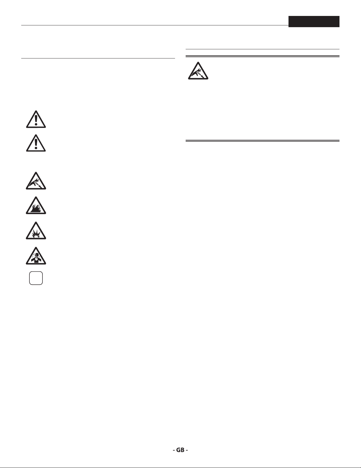
EXPLANATION OF SYMBOLS USED
This symbol indicates a potential hazard
that may cause serious injury or loss of life.
Important safety information will follow.
This symbol indicates a potential hazard
to you or to the equipment. Important
tention
information that tells how to prevent
damage to the equipment or how to avoid
causes of minor injuries will follow.
Danger of skin injection
Danger of re from solvent and paint fumes
Danger of explosion from solvent, paint
fumes and incompatible materials
Danger of injury from inhalation of harmful
vapors
Notes give important information which
should be given special attention.
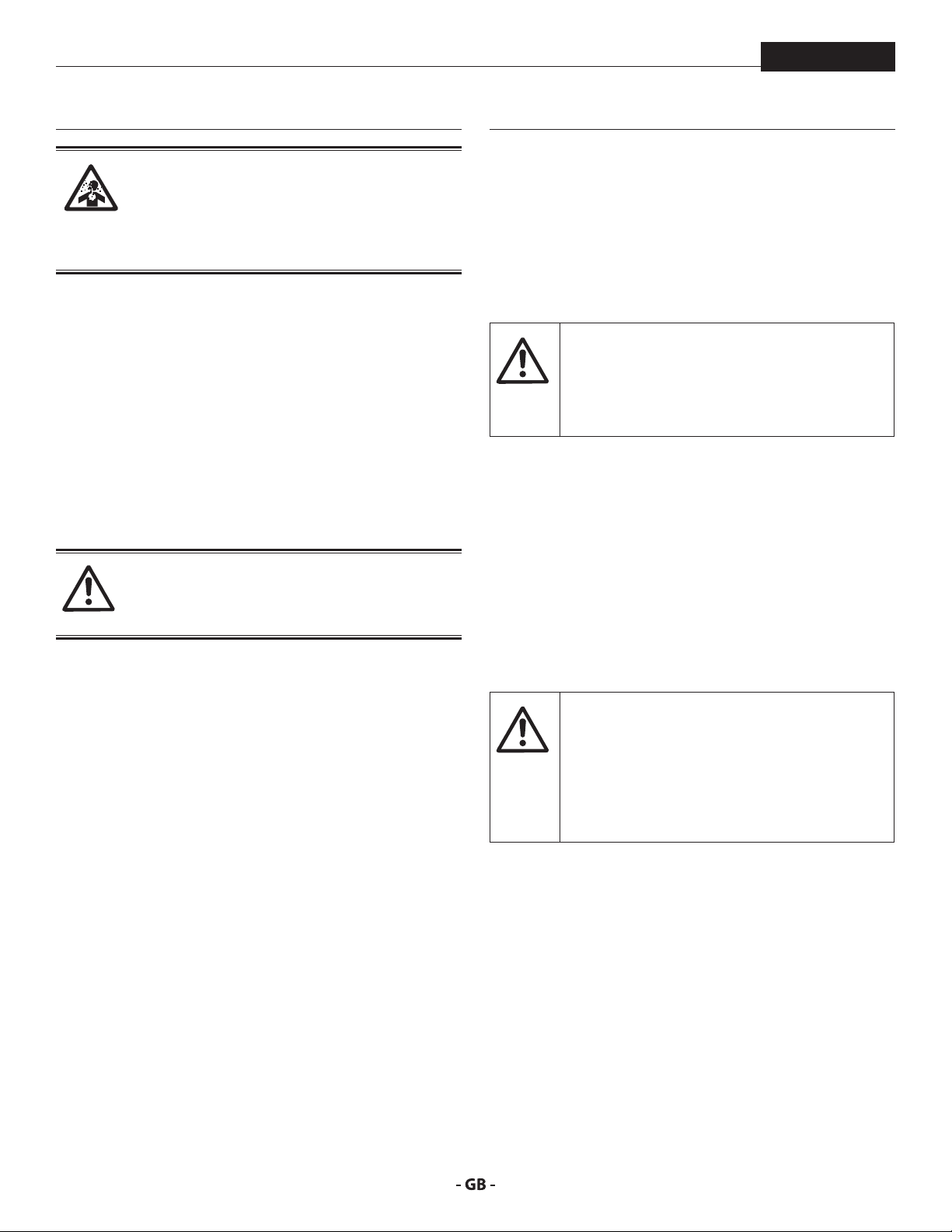
HAZARD: INJECTION INJURY
pressure stream produced by this equipment can
pierce the skin and underlying tissues, leading to
serious injury and possible amputation.
Do not treat a spraying injury as a harmless cut. In
case of injury to the skin through coating materials
about the coating material or solvent used.
PREVENTION:
• NEVER aim the gun at any part of the body.
• NEVER allow any part of the body to touch the uid stream.
DO NOT allow body to touch a leak in the uid hose.
• NEVER put your hand in front of the gun. Gloves will not
provide protection against an injection injury.
• ALWAYS lock the gun trigger, shut the uid pump o and
release all pressure before servicing, cleaning the tip guard,
changing tips, or leaving unattended. Pressure will not be
released by turning o the engine. The PRIME/SPRAY valve
or pressure bleed valve must be turned to their appropriate
positions to relieve system pressure.
• ALWAYS keep tip guard in place while spraying. The tip
guard provides some protection but is mainly a warning
device.
• ALWAYS remove the spray tip before ushing or cleaning
the system.
• NEVER use a spray gun without a working trigger lock and
trigger guard in place.
• All accessories must be rated at or above the maximum
operating pressure range of the sprayer. This includes
spray tips, guns, extensions, and hose.
4
Page 5

SAFETY PRECAUTIONS
The paint hose can develop leaks from wear,
Flammable vapors, such as solvent and paint
ProSpray 20
HAZARD: HIGH PRESSURE HOSE
kinking and abuse. A leak can inject material into
the skin. Inspect the hose before each use.
PREVENTION:
• Avoid sharp bending or kinking of the high-pressure hose.
The smallest bending radius amounts to about 20 cm.
• Do not drive over the high-pressure hose. Protect against
sharp objects and edges.
• Replace any damaged high-pressure hose immediately.
• Never repair defective high-pressure hoses yourself!
• Electrostatic charging of spray guns and the high-pressure
hose is discharged through the high-pressure hose. For this
reason the electric resistance between the connections of
the high-pressure hose must be equal to or lower than
1MΩ.
• For reasons of function, safety and durability use only
original Wagner high-pressure hoses.
• Before each use, check all hoses for cuts, leaks, abrasion
or bulging of cover. Check for damage or movement of
couplings. Immediately replace the hose if any of these
conditions exist. Never repair a paint hose. Replace it with
another earthed high-pressure hose.
• Make sure power cord, air hose and spray hoses are routed
in such a manner to minimize slip, trip and fall hazard.
5
HAZARD: EXPLOSION OR FIRE
vapors, in work area can ignite or explode.
PREVENTION:
• Do not use materials with a ashpoint below 38° C (100° F).
Flashpoint is the temperature at which a uid can produce
enough vapors to ignite.
• Do not use the unit in work places which are covered by
the explosion protection regulations.
• Provide extensive exhaust and fresh air introduction to
keep the air within the spray area free from accumulation
of ammable vapors.
• Avoid all ignition sources such as static electricity sparks,
electrical appliances, ames, pilot lights, hot objects, and
sparks from connecting and disconnecting power cords or
working light switches.
• Do not smoke in spray area.
• Place sprayer sucient distance from the spray object
in a well ventilated area (add more hose if necessary).
Flammable vapors are often heavier than air. Floor area
must be extremely well ventilated. The pump contains
arcing parts that emit sparks and can ignite vapors.
• The equipment and objects in and around the spray area
must be properly grounded to prevent static sparks.
• Use only conductive or earthed high pressure uid hose.
Gun must be earthed through hose connections.
• Power cord must be connected to a grounded circuit
(electric units only).
• Always ush unit into separate metal container, at low
pump pressure, with spray tip removed. Hold gun rmly
against side of container to ground container and prevent
static sparks.
• Follow material and solvent manufacturer’s warnings and
instructions. Be familiar with the coating material’s SDS
sheet and technical information to ensure safe use.
• Use lowest possible pressure to ush equipment.
• When cleaning the unit with solvents, the solvent should
never be sprayed or pumped back into a container with
a small opening (bunghole). An explosive gas/air mixture
can arise. The container must be earthed.
• Do not use a paint or solvent containing halogenated
hydrocarbons. Such as chlorine, bleach, mildewcide,
methylene chloride and trichloroethane. They are not
compatible with aluminum. Contact the coating supplier
about compatibility of material with aluminum.
Page 6
SAFETY PRECAUTIONS
Paints, solvents, and other materials can be
harmful if inhaled or come in contact with body.
Vapors can cause severe nausea, fainting, or
HAZARD: HAZARDOUS VAPORS
poisoning.
PREVENTION:
• Wear respiratory protection when spraying. Read all
instructions supplied with the mask to be sure it will
provide the necessary protection.
• All local regulations regarding protection against
hazardous vapors must be observed.
• Wear protective eyewear.
• Protective clothing, gloves and possibly skin protection
cream are necessary for the protection of the skin. Observe
the regulations of the manufacturer concerning coating
materials, solvents and cleaning agents in preparation,
processing and cleaning units.
HAZARD: GENERAL
This product can cause severe injury or property
damage.
PREVENTION:
• Follow all appropriate local, state, and national codes
governing ventilation, re prevention, and operation.
• Pulling the trigger causes a recoil force to the hand that is
holding the spray gun. The recoil force of the spray gun is
particularly powerful when the tip has been removed and
a high pressure has been set on the airless pump. When
cleaning without a spray tip, set the pressure control knob
to the lowest pressure.
• Use only manufacturer authorized parts. User assumes all
risks and liabilities when using parts that do not meet the
minimum specications and safety devices of the pump
manufacturer.
• ALWAYS follow the material manufacturer’s instructions
for safe handling of paint and solvents.
• Clean up all material and solvent spills immediately to
prevent slip hazard.
• Wear ear protection. This unit can produce noise levels
above 85 dB(A).
• Never leave this equipment unattended. Keep away from
children or anyone not familiar with the operation of airless
equipment.
• Do not spray on windy days.
• The device and all related liquids (i.e. hydraulic oil) must be
disposed of in an environmentally friendly way.
6
ProSpray 20
1.2 ELECTRIC SAFETY
Electric models must be earthed. In the event of an electrical
short circuit, earthing reduces the risk of electric shock by
providing an escape wire for the electric current. This product
is equipped with a cord having an earthing wire with an
appropriate earthing plug. Connection to the mains only
through a special feed point, e.g. through an error protection
insallation with INF < 30 mA.
DANGER — Work or repairs at the electrical
equipment may only be carried out by a skilled
electrician. No liability is assumed for incorrect
installation. Switch the unit o. Before all repair
work, unplug the power plug from the outlet.
Danger of short-circuits caused by water ingressing into the
electrical equipment. Never spray down the unit with highpressure or high-pressure steam cleaners.
WORK OR REPAIRS AT THE ELECTRICAL EQUIPMENT:
These may only be carried out by a skilled electrician. No liability
is assumed for incorrect installation.
1.3 ELECTROSTATIC CHARGING FORMATION OF
SPARKS OR FLAMES
Electrostatic charging of the unit may occur
during spraying due to the ow speed of the
coating material. These can cause sparks and
ames upon discharge. The unit must therefore
always be earthed via the electrical system. The
unit must be connected to an appropriatelygrounded safety outlet.
An electrostatic charging of spray guns and the high-pressure
hose is discharged through the high-pressure hose. For this
reason the electric resistance between the connections of the
high-pressure hose must be equal to or lower than 1 MΩ.
Page 7

GENERAL VIEW OF APPLICATION
i
i
ProSpray 20
2 GENERAL VIEW OF APPLICATION
2.1
The unit performance is conceived so that its use is possible on
building sites for small- to middle-area dispersion work.
EXAMPLES OF OBJECTS TO BE SPRAYED
The sprayer is able for all common varnishing jobs like doors,
door frames, balustrades, furniture, woodencladding, fences,
radiators (heating) and steel parts.
APPLICATION
2.2 COATING MATERIALS
PROCESSIBLE COATING MATERIALS
Pay attention to the Airless quality of the coating
materials to be processed.
Dilutable lacquers and paints or those containing solvents, twocomponent coating materials, dispersions, latex paints, release
agents, oils, undercoats, primers, and llers.
No other materials should be used for spraying without
Wagner’s approval.
FILTERING
Despite suction lter and insertion lter in the spray gun,
ltering of the coating material is generally advisable.
Stir coating material before commencement of work.
Attention: Make sure, when stirring up with
motor-driven agitators that no air bubbles are
stirred in. Air bubbles disturb when spraying and
can, in fact, lead to interruption of operation.
VISCOSITY
With this unit it is possible to process highly viscous coating
materials of up to around 20.000 MPa·s.
If highly viscous coating materials cannot be taken in by suction,
they must be diluted in accordance with the manufacturer’s
instructions.
TWOCOMPONENT COATING MATERIAL
The appropriate processing time must be adhered to exactly.
Within this time rinse through and clean the unit meticulously
with the appropriate cleaning materials.
COATING MATERIALS WITH SHARPEDGED ADDITIONAL
MATERIALS
These have a strong wear and tear eect on valves, highpressure hose, spray gun and tip. The durability of these parts
cane be reduced appreciably through this.
7
Page 8

DESCRIPTION OF UNIT
3 DESCRIPTION OF UNIT
ProSpray 20
3.1
The main areas of application are thick layers of highly viscous
coating material for large areas and a high consumption of
material.
A piston pump takes in the coating material by suction and
conveys it to the tip. Pressed through the tip at a pressure of
up to a maximum of 214 bar (21.4 MPa), the coating material
is atomised. This high pressure has the eect of micro ne
atomisation of the coating material.
As no air is used in this process, it is described as an AIRLESS
process.
This method of spraying has the advantages of nest
atomisation, cloudless operation and a smooth, bubble-free
surface. As well as these, the advantages of the speed of work
and convenience must be mentioned.
AIRLESS PROCESS
3.2 FUNCTIONING OF THE UNIT
In the following there is a short description of the technical
construction for better understanding of the function.
Wagner ProSpray 20 units are electrically driven high-pressure
spraying units.
A gear unit transfers the driving force to a crankshaft. The
crankshaft moves the pistons of the material feed pump up and
down.
The inlet valve is opened automatically by the upwards
movement of the piston. The outlet valve is opened when the
piston moves downward.
The coating material ows under high pressure through the
high-pressure hose to the spray gun. When the coating material
exits from the tip it atomizes.
The pressure control knob controls the volume and the
operating pressure of the coating material.
8
Page 9
DESCRIPTION OF UNIT
3
12
10
11
4
5
6
7
7*
PRIME
SPRAY
k
p
ProSpray 20
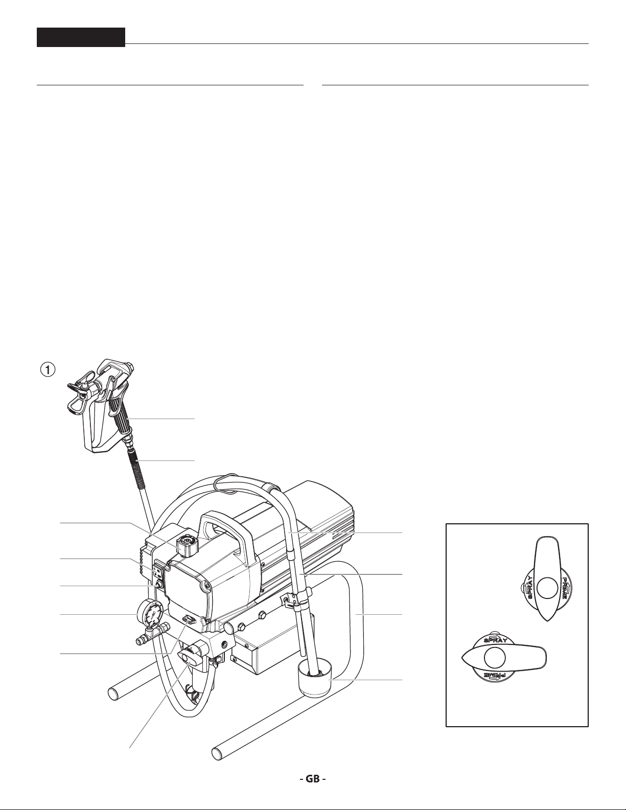
3.3 LEGEND FOR EXPLANATORY DIAGRAM
PROSPRAY 20
1. Spray gun
2. High-pressure hose
3. Return hose
4. Suction hose
5. Frame
6. Drip cup
3.4 EXPLANATORY DIAGRAM PROSPRAY 20
1
7. Relief valve
Lever position vertical – PRIME ( k circulation)
Lever position horizontal – SPRAY ( p)
8. Pressure control knob
9. ON/OFF switch
10. Circuit breaker
11. Pressure gauge
12. Oil cup for EasyGlide (EasyGlide prevents
increased wear of the packings)
2
8
9
9
Page 10
DESCRIPTION OF UNIT / STARTING OPERATION
Attention
ProSpray 20
4 STARTING OPERATION
3.5 TECHNICAL DATA
Voltage
100-110 VAC~, 50/60 Hz or
220-240 VAC~, 50/60 Hz
Max. current consumption
100-110 VAC~
220-240 VAC~
Power Cord
Max. operating pressure
Volume ow at 12 MPa (120 bar) with water
Max tip size
0.021 inch – 0.53 mm
Max. temperature of the coating material
Max viscosity
Weight
15.2 kg
Special high-pressure hose
6,35 mm, 15 m - 1/4” - 18 NPSM
Dimensions (L X W X H)
480 x 360 x 405 mm
Vibration
Spray gun does not exceed 2.5m/s
Max sound pressure level
11.0 A
5.3 A
See page 88
214 bar (21.4 MPa)
1.62 l/min
43°C
20.000 MPa·s
80 dB*
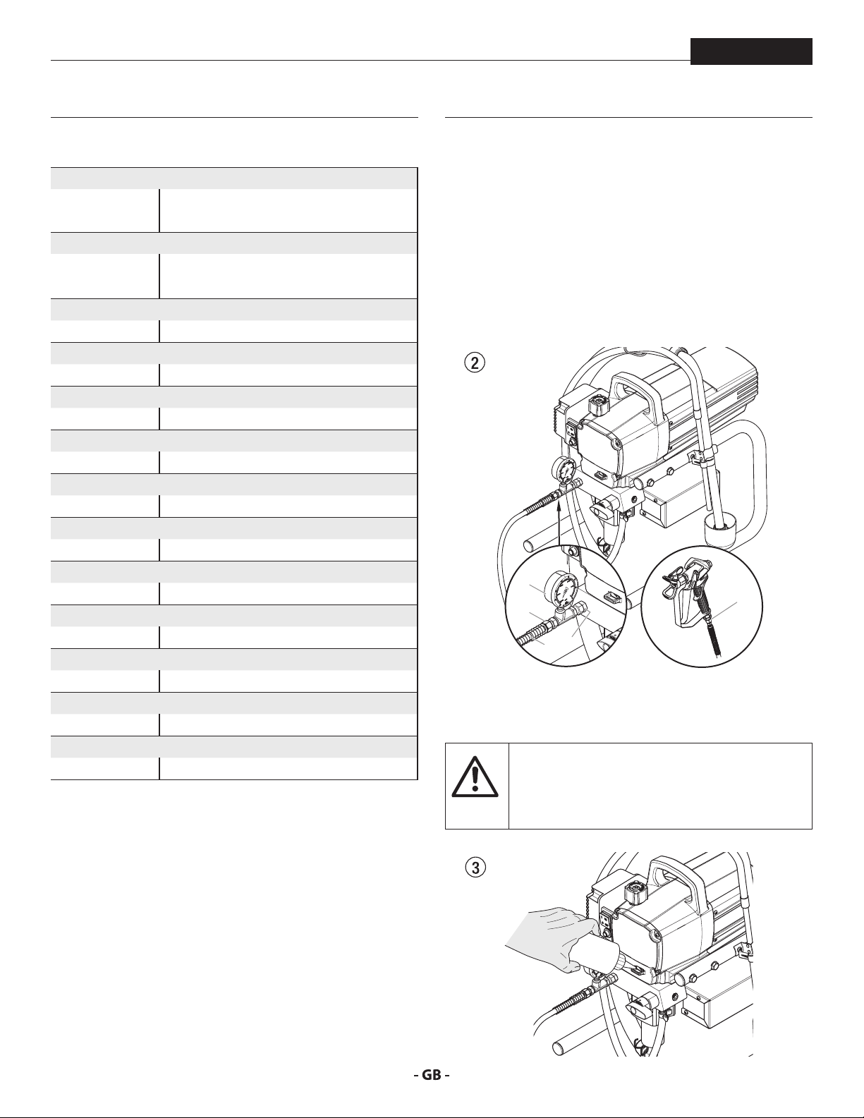
4.1 HIGHPRESSURE HOSE, SPRAY GUN AND
SEPARATING OIL
1. If equipped, screw the pressure gauge (1) to the coating
material outlet (Fig. 2, Item 2).
2. Screw the high-pressure hose (3) to the coating material
outlet (Fig. 2, Item 4).
3. Screw the spray gun (5) with the selected tip onto the
high-pressure hose.
4. Tighten the union nuts at the high-pressure hoses rmly
so that coating material does not leak.
1
4
2
3
5. Fill the oil cup with EasyGlide (Fig. 3). Do not use too much
EasyGlide, i.e. ensure that no EasyGlide drips into the
2
coating material container.
EasyGlide prevents increased wear and tear to
the packings.
5
* Place of measurement: 1 m distance from unit and
1.60m above oor, 12 MPa (120 bar) operating pressure,
reverberant oor
3.6 TRANSPORTATION IN VEHICLE
Secure the unit with a suitable fastening.
10
Page 11
DESCRIPTION OF UNIT
At
i
ProSpray 20
4.2 CONNECTION TO THE MAINS NETWORK
The unit must be connected to an appropriatelygrounded safety outlet.
tention
Before connecting the unit to the mains supply, ensure that the
line voltage matches that specied on the unit’s rating plate.
The connection must be equipped with a residual current
protective device with INF ≤ 30 mA.
Wagner‘s accessories program also includes
a mobile operator protection device for the
electronic supply, which can also be used with
other electronic equipment.
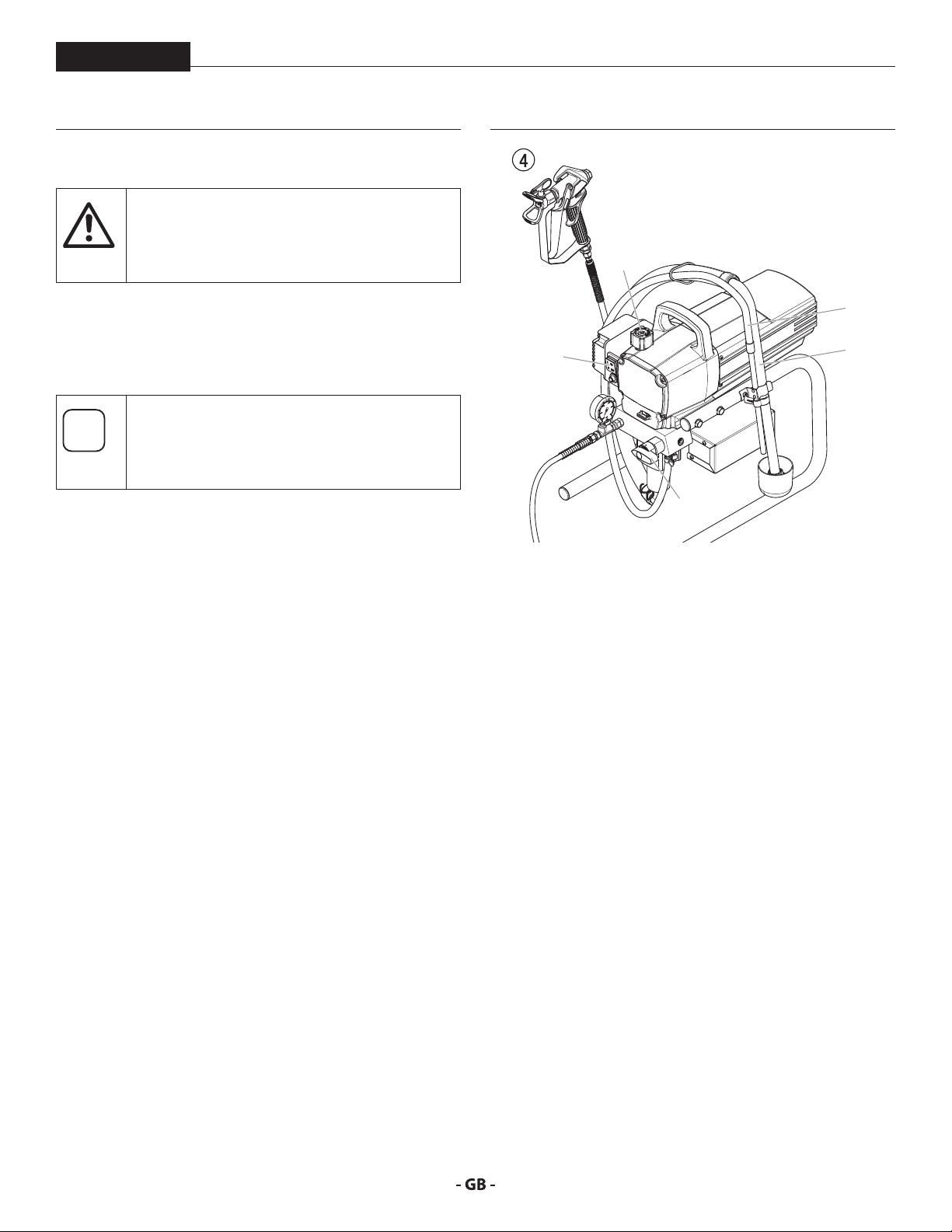
4.3 CLEANING PRESERVING AGENT WHEN
STARTINGUP OF OPERATION INITIALLY
1. Immerse the suction tube (Fig. 4, Item 2) and return hose
(1) into a container with a suitable cleaning agent.
2. Turn the pressure control knob counterclockwise (3) to
minimum pressure.
3. Open the relief valve (4), valve position PRIME (k
circulation).
4. Switch the unit (5) ON.
5. Wait until the cleaning agent exudes from the return hose.
6. Close the relief valve, valve position SPRAY (p spray).
7. Pull the trigger of the spray gun.
8. Spray the cleaning agent from the unit into an open
collecting container.
3
1
5
4
2
4.4 TAKING THE UNIT INTO OPERATION WITH
COATING MATERIAL
1. Immerse the suction tube (Fig. 4, Item 2) and return hose
(1) into the coating material container.
2. Turn the pressure control knob counterclockwise (3) to
minimum pressure.
3. Open the relief valve (4), valve position PRIME (k
circulation).
4. Switch the unit (5) ON.
5. Wait until the coating material exudes from the return
hose.
6. Close the relief valve, valve position SPRAY (p spray).
7. Trigger the spray gun several times and spray into a
collecting container until the coating material exits the
spray gun without interruption.
8. Increase the pressure by slowly turning up the pressure
control knob.
Check the spray pattern and increase the pressure until
the atomization is correct.
Always turn the pressure control knob to the lowest
setting with good atomization.
9. The unit is ready to spray.
11
Page 12
SPRAYING
i
5 SPRAYING
ProSpray 20
Injection hazard. Do not spray without the tip
guard in place. NEVER trigger the gun unless
the tip is completely turned to either the spray
or the unclog position. ALWAYS engage the
gun trigger lock before removing, replacing or
cleaning tip.
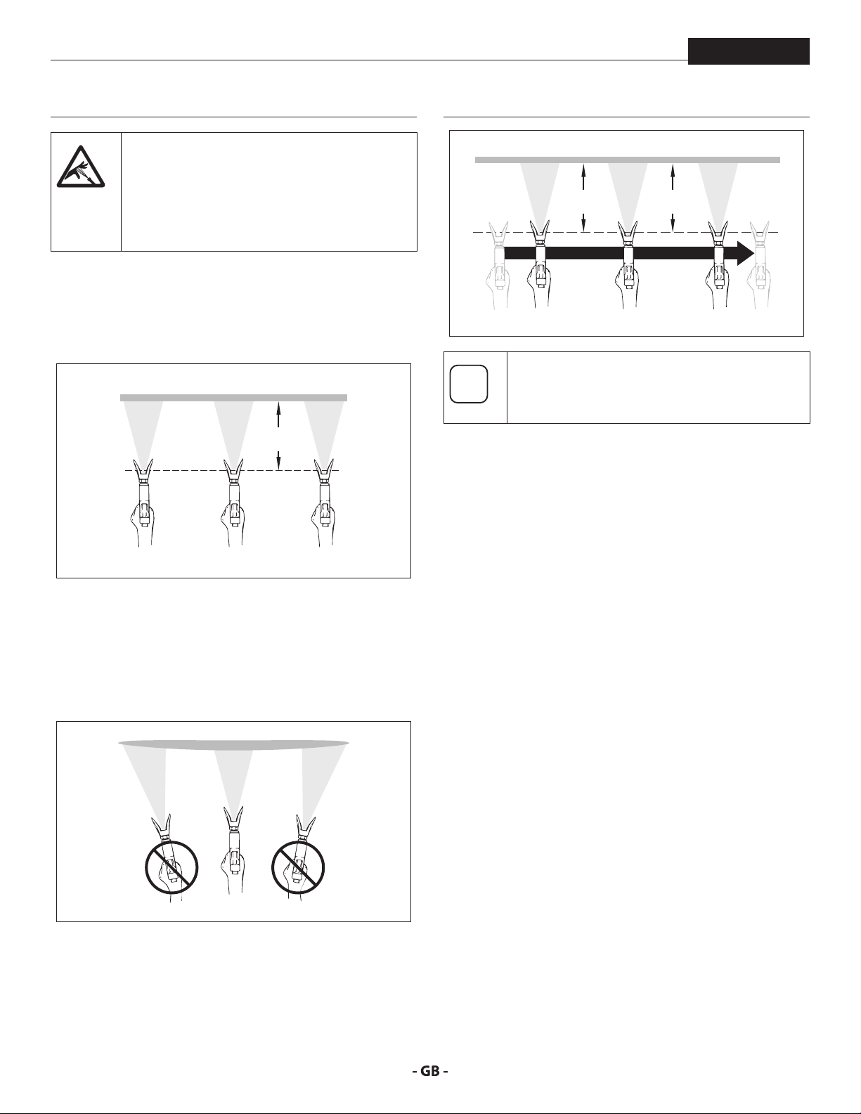
A) The key to a good paint job is an even coating over the
entire surface. Keep your arm moving at a constant
speed and keep the spray gun at a constant distance from
the surface. The best spraying distance is 10-12 inches
(25 to 30 cm) between the spray tip and the surface.
A
25 - 30 cm
C
25 - 30 cm25 - 30 cm
If very sharp edges result or if there are streaks in
the spray jet – increase the operating pressure or
dilute the coating material.
B) Keep the spray gun at right angles to the surface. This
means moving your entire arm back and forth rather than
just exing your wrist.
Keep the spray gun perpendicular to the surface,
otherwise one end of the pattern will be thicker than the
other.
B
C) Trigger gun after starting the stroke. Release the trigger
before ending the stroke. The spray gun should be
moving when the trigger is pulled and released. Overlap
each stroke by about 30%. This will ensure an even
coating.
12
Page 13
HANDLING THE HIGH -PRESSURE HOSE / INTERRUPTION OF WORK
i
i
i
i
At
ProSpray 20
6 HANDLING THE HIGHPRESSURE
HOSE
7 INTERRUPTION OF WORK
The unit is equipped with a high-pressure hose
specially suited for piston pumps.
Danger of injury through leaking high-pressure
hose. Replace any damaged high-pressure hose
immediately.
Never repair defective high-pressure hoses
yourself!
The high-pressure hose is to be handled with care. Avoid sharp
bends and folds: the smallest bending radius is about 8” (20 cm).
Do not drive over the high-pressure hose. Protect against sharp
objects and edges.
Never pull on the high-pressure hose to move the device.
Make sure that the high-pressure hose cannot twist. This can be
avoided by using a Wagner spray gun with a swivel joint and a
hose system.
When using the high-pressure hose while
working on scaolding, it is best to always guide
the hose along the outside of the scaolding.
1. Open the relief valve, valve position PRIME (k circulation).
2. Switch the unit OFF.
3. Turn the pressure control knob counterclockwise to
minimum pressure.
4. Pull the trigger of the spray gun in order to release the
pressure from the high-pressure hose and spray gun.
5. Secure the spray gun, refer to the operating manual of the
spray gun.
6. If a standard tip is to be cleaned, see Page 23, Section 12.2.
If a non-standard tip is installed, proceed according to the
relevant operating manual.
7. Depending on the model, leave the suction tube or the
suction hose and return hose immersed in the coating
material or swivel or immerse it into a corresponding
cleaning agent.
If fast-drying or two-component coating material
is used, ensure that the unit is rinsed with a
tention
suitable cleaning agent within the processing
time.
The risk of damage rises with the age of the highpressure hose. Wagner recommends replacing
high-pressure hoses after 6 years.
Use only Wagner original-high-pressure hoses
in order to ensure functionality, safety and
durability.
13
Page 14

CLEANING THE UNIT (SHUTTING DOWN)
i
i
i
At
Attention
i
8 CLEANING THE UNIT SHUTTING
DOWN
ProSpray 20
A clean state is the best method of ensuring
operation without problems. After you have
nished spraying, clean the unit. Under no
circumstances may any remaining coating
material dry and harden in the unit.
The cleaning agent used for cleaning (only with
an igni tion point above 38 °C) must be suitable
for the coating material used.
• Secure the spray gun, refer to the operating
manual of the spray gun.
• Clean and remove tip.
• For a standard tip, refer to Page 23, Section
12.2.
• If a non-standard tip is installed, proceed
according to the relevant operating manual.
1. Remove suction hose from the coating material.
2. Close the relief valve, valve position SPRAY (p spray).
3. Switch the unit ON.
The container must be earthed in case of coating
materials which contain solvents.
8.1 CLEANING UNIT FROM OUTSIDE
First of all pull out mains plug from socket.
Danger of short circult through penetrating
water!
Never spray down the unit with high-pressure or
high-pressure steam cleaners.
Do not put the high-pressure hose into solvents.
Use only a wet cloth to wipe down the outside of
the hose.
Wipe down unit externally with a cloth which has been
immersed in a suitable cleaning agent.
8.2 SUCTION FILTER
A clean suction lter always guarantees maximum
feed quantity, constant spraying pressure and
problem-free functioning of the unit.
tention
Caution! Do not pump or spray into a container
with a small opening (bunghole)!
4. Pull the trigger of the spray gun in order to pump the
remaining coating material from the suction hose, highpressure hose and the spray gun into an open container.
5. Immerse suction hose with return hose into a container
with a suitable cleaning agent.
6. Turn the pressure control knob counterclockwise to
minimum pressure.
7. Open the relief valve, valve position PRIME (k circulation).
8. Pump a suitable cleaning agent in the circuit for a few
minutes.
9. Close the relief valve, valve position SPRAY (p spray).
10. Pull the trigger of the spray gun.
11. Pump the remaining cleaning agent into an open container
until the unit is empty.
12. Switch the unit OFF.
1. Screw o the lter (Fig. 5) from suction tube.
2. Clean or replace the lter.
Carry out cleaning with a hard brush and an appropriate
cleaning agent.
14
Page 15

CLEANING THE UNIT (SHUTTING DOWN)
i
i
ProSpray 20
8.3 CLEANING THE HIGHPRESSURE FILTER
Clean the lter cartridge regularly. A soiled or
clogged high-pressure lter can cause a poor
spray pattern or a clogged tip.
1. Turn the pressure control knob counterclockwise to
minimum pressure.
2. Open the relief valve, valve position PRIME (k circulation).
3. Switch the unit OFF.
Unplug the power plug from the outlet.
4. Unscrew the lter housing (Fig. 6, Item 1). with a strap
wrench.
5. Pull the lter cartridge (2) from the manifold (3).
6. Clean all the parts with the corresponding cleaning agent.
If necessary, replace the lter cartridge.
7. Check the O-ring (4), replace it if necessary.
8. Push the new or cleaned lter into the pump manifold.
9. Screw in lter housing (1) and tighten it as far as possible
with the strap wrench.
8.4 CLEANING AIRLESS SPRAY GUN
Clean the spray gun after each use.
1. Rinse airless spray gun with an appropriate cleaning agent.
2. Clean tip thoroughly with appropriate cleaning agent so
that no coating material residue remains.
3. Thoroughly clean the outside of the airless spray gun.
INTAKE FILTER IN AIRLESS SPRAY GUN FIG. 7
1. Unclip the top of the trigger guard (1) from the gun head.
2. Using the bottom of the trigger guard as a wrench, loosen
and remove the handle assembly (2) from the gun head.
3. Pull the old lter (3) out of the gun head. Clean or replace.
4. Slide the new lter, tapered end rst, into the gun head.
5. Thread the handle assembly into the gun head. Tighten
with the trigger wrench.
6. Snap the trigger guard back onto the gun head.
1
2
3
4
3
15
1
2
Page 16

REMEDY IN CASE OF FAULTS
9 REMEDY IN CASE OF FAULTS
ProSpray 20
Type of malfunction
A. Unit does not start
B. Unit does not draw in material
C. Unit draws in material, but the
pressure does not build up
D. Coating material exits at the top of
the uid section
E. Increased pulsation at the spray
gun
Possible cause
1. No voltage applied.
2. Pressure setting too low.
3. ON/OFF switch defective.
1. Relief valve is set to SPRAY (p spray).
2. Filter projects over the uid level and
sucks air.
3. Filter clogged.
4. Suction hose/suction tube is loose, i.e.
the unit is sucking in outside air.
1. Tip heavily worn.
2. Tip too large.
3. Pressure setting too low.
4. Filter clogged.
5. Coating material ows through the
return hose when the relief valve is in
the SPRAY (p spray) position.
6. Packings sticky or worn.
7. Valve balls worn.
8. Valve seats worn.
1. Upper packing is worn.
2. Piston is worn.
1. Incorrect high-pressure hose type.
2. Tip worn or too large.
3. Pressure too high.
Measures for eliminating the malfunction
1. Check voltage supply.
2. Turn up pressure control knob.
3. Replace.
1. Set relief valve to PRIME (k circulation).
2. Rell the coating material.
3. Clean or replace the lter.
4. Clean connecting points. Replace O-rings if necessary.
Secure suction hose with retaining clip.
1. Replace
2. Replace tip.
3. Turn pressure control knob clockwise to increase.
4. Clean or replace the lter.
5. Remove and clean or replace relief valve.
6. Remove and clean or replace packings.
7. Remove and replace valve balls.
8. Remove and replace valve seats.
1. Remove and replace packing.
2. Remove and replace piston.
1. Only use WAGNER original-high-pressure hoses in order
to ensure functionality, safety and durability.
2. Replace tip.
3. Turn pressure control knob to a lower number.
F. Poor spray pattern
G. Unit loses power
H. Pump over-pressurizes and will not
shut o.
1. Tip is too large for the coating
material which is to be sprayed.
2. Pressure setting incorrect.
3. Volume too low.
4. Coating material viscosity too high.
1. Pressure setting too low.
1. Pressure switch defective.
2. Transducer defective.
1. Replace tip.
2. Turn pressure control knob until a satisfactory spraying
pattern is achieved.
3. Clean or replace all lters.
4. Thin out according to the manufacturer’s instructions.
1. Turn pressure control knob clockwise to increase.
1. Take unit to a Wagner authorized service center.
2. Take unit to a Wagner authorized service center.
16
Page 17

SERVICING / REPAIRS AT THE UNIT
i
i
At
ProSpray 20
10 SERVICING
10.1
Servicing of the unit should be carried out once annually by the
WAGNER service.
1. Check high-pressure hoses, device connecting line and
2. Check the inlet valve, outlet valve and lter for wear.
10.2 HIGHPRESSURE HOSE
Inspect the high-pressure hose visually for any notches or
bulges, in particular at the transition in the ttings. It must be
possible to turn the union nuts freely.
GENERAL SERVICING
plug for damage.
The risk of damage rises with the age of the highpressure hose. Wagner recommends replacing
high-pressure hoses after 6 years.
11 REPAIRS AT THE UNIT
Switch the unit OFF.
Before all repair work: Unplug the power plug
from the outlet.
Make sure to check for grounding continuity
after service is performed on any electrical
components.
Use an ohmmeter to determine that there is
continuity between accessible dead-metal parts
of the product and the grounding blade of the
attachment plug.
11.1 RELIEF VALVE
The valve housing (4) should not be repaired. If
worn, it should always be replaced with a new
tention
one.
1. Use a drift punch of 2 mm to remove the grooved pin (Fig.
8, Item 1) from the relief valve handle (2).
2. Remove the relief valve handle (2) and cam base (3).
3. Using a wrench, remove the valve housing (4) from the
pump manifold (6).
4. Ensure that the seal (5) is seated correctly, then screw the
new valve housing (4) completely into the pump manifold
(6). Tighten securely with a wrench.
5. Align the cam base (3) with the hole in the pump manifold
(6). Lubricate the cam base with grease and slide on the
cam base.
6. Bring the hole in the valve shaft (7) and in the relief valve
handle (2) into alignment.
7. Insert the grooved pin (1) to secure the relief valve handle
in position.
6
4
1
7
2
17
3
5
Page 18

REPAIRS AT THE UNIT
ProSpray 20
11.2 INLET AND OUTLET VALVE
1. Remove the four screws in the front cover and then remove
the front cover.
2. Switch the unit ON and then OFF so that the piston rod is
positioned in the lower stroke position.
Danger of crushing - do not reach with the ngers
or tool between the moving parts.
3. Unplug the power plug from the outlet.
4. Remove the retaining clip from the connecting bend at the
suction hose and pull o the suction hose.
5. Screw o the return hose.
6. Swivel the unit 90° to the rear in order to work more easily
on the material feed pump.
7. Unscrew the inlet valve housing (Fig. 10, Item 1) from the
pump manifold.
8. Remove the lower seal (2), lower ball guide (3), inlet valve
ball (4), inlet valve seat (5) and O-ring (6).
9. Clean all the parts with the corresponding cleaning agent.
Check the inlet valve housing (1), inlet valve seat (5)
and inlet valve ball (4) for wear and replace the parts if
necessary. If the worn inlet valve seat (5) is unused on one
side, install it the other way round.
12. Clean all the parts with the corresponding cleaning agent.
Check outlet valve housing (7), outlet valve seat (12),
outlet valve ball (11) and upper ball guide (10) for wear
and replace parts if necessary. If the worn outlet valve seat
(12) is unused on one side, install it the other way round.
13. Carry out installation in the reverse order. Lubricate O-ring
(Fig. 9, Item 6) with machine grease and ensure proper
seating in the inlet valve housing (Fig. 10, Item 1).
8
10
9
11
12
7
2
3
4
5
6
1
10. Unscrew outlet valve housing (Fig. 11, Item 7) from the
piston (8) with adjusting wrench.
11. Remove the upper ball guide (10), crush washer (9) outlet
valve ball (11), and outlet valve seat (12).
18
Page 19

REPAIRS AT THE UNIT
ProSpray 20
11.3 PACKINGS
1. Remove inlet valve housing in accordance with the steps
in Chapter 11.2.
2. It is not necessary to remove the outlet valve.
3. Unscrew both cylinder head screws (Fig. 12, Item 1) from
the pump manifold (2) with a 3/8 inch hexagon socket
head wrench.
4. Slide the pump manifold (2) and piston (3) forward until
the piston is out of the T-slot (10) on the slider assembly
(5).
5. Push piston (3) downward out of the pump manifold (2).
6. Unscrew retainer nut (6) from the pump manifold (2) and
remove piston guide (7).
7. Remove upper packing (8) and lower packing (9) from the
pump manifold (2).
5
10
6
7
8
2
1
9
3
8. Clean pump manifold (2).
9. Lubricate upper packing (8) and lower packing (9) with
machine grease.
10. Insert upper packing (Fig. 13) with O-ring (1) and
protruding lip (2) downward.
11. Insert lower packing (Fig. 14) with the beveled edge (1)
facing upward.
12. Insert piston guide (Fig. 12, Item 7) into the retainer nut
(6). Screw retainer nut (6) into the pump manifold (2) and
tighten by hand.
13. Push installation tool (included with the replacement
packings) for the piston (3) from above onto the piston.
14. Lubricate installation tool and piston (3) with machine
grease.
15. Guide piston (3) through the lower packings (9) into the
pump manifold (2) from below. Using a rubber mallet,
lightly tap the piston (3) from below until it can be seen
above the pump manifold.
16. Remove installation tool from piston (3).
17. Carefully tighten retainer nut (6) with adjusting wrench.
18. Slide the top of the piston (3) into the T-slot (10) on the
slider assembly (4).
19. Position the pump manifold (2) underneath the gear unit
housing and push up until it rests against the gear unit
housing.
20. Attach pump manifold (2) to the gear unit housing. Ensure
that the pressure sensor does not damage the pressure
sensor seal (10).
21. Screw pump manifold (2) tightly to gear unit housing.
22. Lubricate O-ring (Fig. 10, Item 6) between pump manifold
(2) and inlet valve housing with machine grease. Screw
inlet valve housing to the pump manifold.
23. Push connection bend of suction hose into the inlet valve
housing (Fig. 10, Item 1) and secure with retaining clip.
Screw on return hose and clamp to suction hose.
24. Install front cover.
1
2
1
19
Page 20

REPAIRS AT THE UNIT
i
i
3
11.4 REPLACING THE MOTOR
ProSpray 20
1. Open the relief valve, valve position PRIME (k circulation),
switch the unit OFF, and unplug the power cord.
2. Remove the four motor cover screws (Fig. 15, Item 1).
Remove the motor cover (2).
3. Remove the four heat sink assembly screws (3). Pull the
heat sink assembly (4) away from the gear box housing (5).
4. Disconnect the ve wires from the relay (6) that is mounted
on the inside of the heat sink assembly.
5. Connect the ve wires to the relay (refer to the electrical
schematic in section 11.8 of this manual).
6. Using the four heat sink assembly screws (3), install the
heat sink assembly (4) onto the gear box housing (5).
Tighten the screws securely.
7. Disconnect the black and red wires coming from the gear
box housing. Disconnect the black and red wires from the
capacitors (8). Disconnect the black and red wires from
the motor (9).
8. Loosen and remove the four motor mounting screws (10).
9. Pull the motor out of the gear box housing.
If the motor will not dislodge from the pump
housing:
• Remove the front cover plate.
• Using a rubber mallet, carefully tap on the
front of the motor crankshaft that extends
through the slider assembly.
10. With the motor removed, inspect the gears in the gear box
housing for damage or excessive wear. Replace the gears,
if necessary.
11. Install the new motor into the gear box housing.
Rotate the motor fan manually until the armature
gear engages with the mating gear in the gear
box housing.
5
4
6
1
2
9
8
10
11.5 CARBON BRUSHES IN MOTOR MOTOR
BRUSH KIT P/N 704276
1. Remove the four screws (Fig. 16, Item 1) at the motor cover
(2). Remove motor cover.
2. Remove the two screws (3) at the shells (4). Remove shells.
3. Lift up both covers (5) with a small screwdriver.
4. Pull red wire (6) and black wire (7) out of the respective
carbon brush.
5. Insert new carbon brush and snap cover (5) into place.
6. Insert red wire (6) and black wire (7) onto the respective
carbon brush.
7. Screw down both shells (4).
8. Push motor cover (2) over the motor and fasten with the
four screws (1).
7
3
4
1
12. Secure the motor (9) with the four motor mounting screws
(10).
13. Push the new capacitors into their clip (8) on the new
motor.
14. Reconnect the wires (refer to the electrical schematic in
the section 11.8 of this manual).
15. Slide the motor cover (2) over the motor. Secure the motor
cover with the four motor cover screws (1).
20
2
5
6
Page 21

REPAIRS AT THE UNIT
i
i
ProSpray 20
11.6 REPLACING THE GEARS
1. Open the relief valve, valve position PRIME (k circulation),
switch the unit OFF, and unplug the power cord.
2. Loosen and remove the four motor cover screws (Fig. 17.
1). Remove the motor cover (2).
3. Disconnect the black and red wires coming from the gear
box housing.
4. Loosen and remove the four motor mounting screws (3).
5. Pull the motor (4) out of the gear box housing (5).
If the motor will not dislodge from the pump
housing:
• Remove the front cover plate.
• Using a rubber mallet, carefully tap on the
front of the motor crankshaft that extends
through the slider assembly.
6. Inspect the armature gear (6) on the end of the motor for
damage or excessive wear. If this gear is completely worn
out, replace the entire motor.
7. Remove and inspect the 2nd stage gear (7) for damage or
excessive wear. Replace if necessary.
8. Remove and inspect the crankshaft/gear assembly (8) for
damage or excessive wear. Replace if necessary.
9. Reassemble the pump by reversing the above steps.
During reassembly, make sure the thrust washer (9) is in
place.
11.7 REPLACING THE TRANSDUCER
1. Open the relief valve, valve position PRIME (k circulation),
switch the unit OFF, and unplug the power cord.
2. Loosen and remove the four front cover screws (Fig. 18,
Item 1). Remove the front cover (2).
3. Stop the sprayer at the bottom of its stroke so that the
piston is in its lowest position.
4. Tilt the sprayer back for easy access to the uid section.
5. Using 3/8” a hex wrench, loosen and remove the two
pump manifold mounting screws (5).
6. Pull the pump manifold (6) down approximately 1.3 cm
from the pump housing to clear the transducer.
7. Slide the pump block and piston rod forward until the
piston rod is out of the T-slot (4) on the slider assembly (3).
8. Using a wrench, remove the transducer assembly (8) from
the pump manifold.
9. Thread the new transducer assembly into the pump
manifold (6). Tighten securely with a wrench.
10. Reassemble the pump by reversing steps 2–7.
Make sure the transducer is aligned properly
with the hole in the pump manifold during
reassembly. Improper alignment may cause
damage to the transducer o-ring.
Rell the gear box in the pump housing with ve
ounces of Lubriplate GR132 (P/N 0293396).
2
1
2
1
3
4
5
4
7
3
8
6
6
7
8
9
21
5
Page 22

REPAIRS AT THE UNIT
11.8 PROSPRAY 20 CONNECTION DIAGRAM
ProSpray 20
Black
WH4
WH6
White
Blue
WH1
Microswitch
Blue
WH5
Black
WH7
WH2
Red
FB
MB
M
MB
M
F
Capacitors
F
F
Circuit
F
M
M
breaker
+
FB
Red
Red
+
F
Motor
Black Black
F
22
White
Black
Power cord
Blue /
Blue /
white
black
Brown /
EMI
lter
white
F
F
black
Brown /
4
3
2
1
F
F
Switch
Page 23

APPENDIX
ProSpray 20
12 APPENDIX
12.1
SELECTION OF TIP
To achieve faultless and rational working, the selection of the
tip is of the greatest importance.
In many cases the correct tip can only be determined by means
of a spraying test.
SOME RULES FOR THIS:
The spray jet must be even.
If streaks appear in the spray jet the spraying pressure is either
too low or the viscosity of the coating material to high.
REMEDY: Increase pressure or dilute coating material. Each
pump conveys a certain quantity in proportion to the size of
the tip:
The following principle is valid: large tip = low pressure
small tip = high pressure
There is a large range of tips with various spraying angles.
12.3 SPRAY GUN ACCESSORIES
12.2 SERVICING AND CLEANING OF AIRLESS
HARDMETAL TIPS
STANDARD TIPS
If a dierent tip type has been tted, then clean it according to
manufacturer’s instructions.
The tip has a bore processed with the greatest precision. Careful
handling is necessary to achieve long durability. Do not forget
the fact that the hard-metal insert is brittle! Never throw the tip
or handle with sharp metal objects.
The following points must be observed to keep the tip
clean and ready for use:
1. Turn the relief valve handle fully counterclockwise (k
Circulation).
2. Remove the tip from the spray gun.
3. Place tip in an appropriate cleaning agent until all coating
material residue is dissolved.
4. If there is high-pressure air available, blow out tip.
5. Remove any residue by means of a sharp wooden rod
(toothpick).
6. Check the tip with the help of a magnifying glass and, if
necessary, repeat points 3 to 5.
Flat jet adjusting tip
up to 250 bar (25 MPa
Tip
marking
15 0.13 - 0.46 5 - 35 cm Paints 0999 057
20 0.18 - 0.48 5 - 50 cm Paints, llers 0999 053
28 0.28 - 0.66 8 - 55 cm Paints, dispersions 0999 054
41 0.43 - 0.88 10 - 60 cm Rust protection paints
49 0.53 - 1.37 10 - 40 cm Large-area coats 0999 056
Tip extension with
slewable knee joint
(without tip)
Length: 100 cm Order no. 0096 015
Length: 200 cm Order no. 0096 016
Length: 300 cm Order no. 0096 017
Bore mm
Spray width at about 30 cm
removal of spray object
Pressure 100 bar (10 MPa)
Use
- dispersions
Tip extension
15 cm, F-thread, Order no. 0556 051 15 cm, G-thread, Order no. 0556 074
30 cm, F-thread, Order no. 0556 052 30 cm, G-thread, Order no. 0556 075
45 cm, F-thread, Order no. 0556 053 45 cm, G-thread, Order no. 0556 076
60 cm, F-thread, Order no. 0556 054 60 cm, G-thread, Order no. 0556 077
adjusting tip
Flat jet
Order No.
0999 055
Contact protection
for the at jet adjustment tip
Order No. 0097 294
23
Page 24

APPENDIX
i
12.4 AIRLESS TIP TABLE
ProSpray 20
Wagner
TradeTip 3 tip
up to 270 bar
(27 MPa)
without tip
F thread (11/16 - 16 UN)
for Wagner spray guns
Order no. 0289391
All of the tips in the table below are supplied
together with the appropriate gun lter.
Application Tip marking Spray
Water-thinnable and solvent-based
paints and varnishes, oils, separating agents
Synthetic-resin paints
PVC paints
Paints, primers
Fillers
Fillers
Rust protection paints
Rust protection paints
Latex paints
Dispersions
Rust protection paints
Latex paints
Dispersions
107
207
307
407
109
209
309
409
509
609
111
211
311
411
511
611
113
213
313
413
513
613
813
115
215
315
415
515
615
715
815
117
217
317
417
517
617
717
817
219
319
419
519
619
719
819
919
angle
10°
20°
30°
40°
10°
20°
30°
40°
50°
60°
10°
20°
30°
40°
50°
60°
10°
20°
30°
40°
50°
60°
80°
10°
20°
30°
40°
50°
60°
70°
80°
10°
20°
30°
40°
50°
60°
70°
80°
20°
30°
40°
50°
60°
70°
80°
90°
Bore
inch / mm
0.007 / 0.18
0.007 / 0.18
0.007 / 0.18
0.007 / 0.18
0.009 / 0.23
0.009 / 0.23
0.009 / 0.23
0.009 / 0.23
0.009 / 0.23
0.009 / 0.23
0.011 / 0.28
0.011 / 0.28
0.011 / 0.28
0.011 / 0.28
0.011 / 0.28
0.011 / 0.28
0.013 / 0.33
0.013 / 0.33
0.013 / 0.33
0.013 / 0.33
0.013 / 0.33
0.013 / 0.33
0.013 / 0.33
0.015 / 0.38
0.015 / 0.38
0.015 / 0.38
0.015 / 0.38
0.015 / 0.38
0.015 / 0.38
0.015 / 0.38
0.015 / 0.38
0.017 / 0.43
0.017 / 0.43
0.017 / 0.43
0.017 / 0.43
0.017 / 0.43
0.017 / 0.43
0.017 / 0.43
0.017 / 0.43
0.019 / 0.48
0.019 / 0.48
0.019 / 0.48
0.019 / 0.48
0.019 / 0.48
0.019 / 0.48
0.019 / 0.48
0.019 / 0.48
without tip
G thread (7/8 - 14 UN)
for Graco/Wagner spray guns
Order no. 0289390
Spraying
width mm 1)
100
120
150
190
100
120
150
190
225
270
100
120
150
190
225
270
100
120
150
190
225
270
330
100
120
150
190
225
270
300
330
100
120
150
190
225
270
300
330
120
150
190
225
270
300
330
385
Gun lter Order no.
red
red
red
red
red
red
red
red
red
red
red
red
red
red
red
red
red
red
red
red
red
red
red
yellow
yellow
yellow
yellow
yellow
yellow
yellow
yellow
white
white
white
white
white
white
white
white
white
white
white
white
white
white
white
white
0553107
0553207
0553307
0553407
0553109
0553209
0553309
0553409
0553509
0553609
0553111
0553211
0553311
0553411
0553511
0553611
0553113
0553213
0553313
0553413
0553513
0553613
0553813
0553115
0553215
0553315
0553415
0553515
0553615
0553715
0553815
0553117
0553217
0553317
0553417
0553517
0553617
0553717
0553817
0553219
0553319
0553419
0553519
0553619
0553719
0553819
0553919
1)Spray width at about 30 cm to the object and 100 bar (10 MPa) pressure with synthetic-resin paint 20 DIN seconds.
24
Page 25

APPENDIX
ProSpray 20
Application Tip marking Spray
Flame retardant 221
Roof coatings 223
Thick-lm materials,
Corrosion protection
Spray ller
Heavy duty applications 243
321
421
521
621
721
821
323
423
523
623
723
823
225
325
425
525
625
725
825
227
327
427
527
627
827
229
329
429
529
629
231
331
431
531
631
731
831
233
333
433
533
633
235
335
435
535
635
735
439
539
639
443
543
643
445
545
645
451
551
651
252
455
555
655
261
461
561
661
263
463
565
665
267
467
angle
20°
30°
40°
50°
60°
70°
80°
20°
30°
40°
50°
60°
70°
80°
20°
30°
40°
50°
60°
70°
80°
20°
30°
40°
50°
60°
80°
20°
30°
40°
50°
60°
20°
30°
40°
50°
60°
70°
80°
20°
30°
40°
50°
60°
20°
30°
40°
50°
60°
70°
40°
50°
60°
20°
40°
50°
60°
40°
50°
60°
40°
50°
60°
20°
40°
50°
60°
20°
40°
50°
60°
20°
40°
50°
60°
20°
40°
Bore
inch / mm
0.021 / 0.53
0.021 / 0.53
0.021 / 0.53
0.021 / 0.53
0.021 / 0.53
0.021 / 0.53
0.021 / 0.53
0.023 / 0.58
0.023 / 0.58
0.023 / 0.58
0.023 / 0.58
0.023 / 0.58
0.023 / 0.58
0.023 / 0.58
0.025 / 0.64
0.025 / 0.64
0.025 / 0.64
0.025 / 0.64
0.025 / 0.64
0.025 / 0.64
0.025 / 0.64
0.027 / 0.69
0.027 / 0.69
0.027 / 0.69
0.027 / 0.69
0.027 / 0.69
0.027 / 0.69
0.029 / 0.75
0.029 / 0.75
0.029 / 0.75
0.029 / 0.75
0.029 / 0.75
0.031 / 0.79
0.031 / 0.79
0.031 / 0.79
0.031 / 0.79
0.031 / 0.79
0.031 / 0.79
0.031 / 0.79
0.033 / 0.83
0.033 / 0.83
0.033 / 0.83
0.033 / 0.83
0.033 / 0.83
0.035 / 0.90
0.035 / 0.90
0.035 / 0.90
0.035 / 0.90
0.035 / 0.90
0.035 / 0.90
0.039 / 0.99
0.039 / 0.99
0.039 / 0.99
0.043 / 1.10
0.043 / 1.10
0.043 / 1.10
0.043 / 1.10
0.045 / 1.14
0.045 / 1.14
0.045 / 1.14
0.051 / 1.30
0.051 / 1.30
0.051 / 1.30
0.052 / 1.32
0.055 / 1.40
0.055 / 1.40
0.055 / 1.40
0.061 / 1.55
0.061 / 1.55
0.061 / 1.55
0.061 / 1.55
0.063 / 1.60
0.063 / 1.60
0.065 / 1.65
0.065 / 1.65
0.067 / 1.70
0.067 / 1.70
Spraying
width mm 1)
120
150
190
225
270
300
330
120
150
190
225
270
300
330
120
150
190
225
270
300
330
120
150
190
225
270
330
120
150
190
225
270
120
150
190
225
270
300
330
120
150
190
225
270
120
150
190
225
270
300
190
225
270
120
190
225
270
190
225
270
190
225
270
120
190
225
270
120
190
225
270
120
190
225
270
120
190
Gun lter Order no.
white
white
white
white
white
white
white
white
white
white
white
white
white
white
white
white
white
white
white
white
white
white
white
white
white
white
white
white
white
white
white
white
white
white
white
white
white
white
white
white
white
white
white
white
white
white
white
white
white
white
white
white
white
green
green
green
green
green
green
green
green
green
green
green
green
green
green
green
green
green
green
green
green
green
green
green
green
0553221
0553321
0553421
0553521
0553621
0553721
0553821
0553223
0553323
0553423
0553523
0553623
0553723
0553823
0553225
0553325
0553425
0553525
0553625
0553725
0553825
0553227
0553327
0553427
0553527
0553627
0553827
0553229
0553329
0553429
0553529
0553629
0553231
0553331
0553431
0553531
0553631
0553731
0553831
0553233
0553333
0553433
0553533
0553633
0553235
0553335
0553435
0553535
0553635
0553735
0553439
0553539
0553639
0553243
0553443
0553543
0553643
0553445
0553545
0553645
0553451
0553551
0553651
0553252
0553455
0553555
0553655
0553261
0553461
0553561
0553661
0553263
0553463
0553565
0553665
0553267
0553467
1)Spray width at about 30 cm to the object and 100 bar (10 MPa) pressure with synthetic-resin paint 20 DIN seconds.
25
Page 26

APPENDIX
12.5 2SPEED TIP TABLE
The innovative changeover nozzle from WAGNER
combines two nozzle cores into one nozzle.
2 Speed Tip holder
Order no. 0271065
Tip table
Object size Painting material
Lacquer (L) Emulsion (D) Filler (S)
D5
Nozzles: 111 / 415
Order no. 0271 062
D7
Small
L10
Nozzles: 208 / 510
Order no. 0271 042
L20
Medium
Large
X-Large
Recommended gun lter red white -
Nozzles: 210 / 512
Order no. 0271 043
L30
Nozzles: 212 / 514
Order no. 0271 044
Nozzles: 113 / 417
Order no. 0271 063
D10
Nozzles: 111 / 419
Order no. 0271 045
D20
Nozzles: 115 / 421
Order no. 0271 046
D30
Nozzles: 115 / 423
Order no. 0271 047
D40
Nozzles: 117 / 427
Order no. 0271 048
S5
Nozzles: 225 / 629
Order no. 0271 064
S10
Nozzles: 527 / 235
Order no. 0271 049
S20
Nozzles: 539 / 243
Order no. 0271 050
S30
Nozzles: 543 / 252
Order no. 0271 051
ProSpray 20
26
Page 27

APPENDIX
ProSpray 20
12.6 NOZZLE CASES
Nozzle cases are a perfect addition to your paint spraying equipment, with
everything safely stowed away and with project-specic equipment. Ideally
matched to meet your particular application, there are four dierent versions
available.
Part No.
Nozzle case HEA ProTip Emulsion 2391870
u
• 3x gun lter white, 50 MA, 0.31 mm MW, medium 0034 377
• 1x gun lter red, 180 MA, 0.084 mm MW, extra ne 0043 235
• Nozzle extension complete, 15 cm, G-thread 0556 074
• HEA ProTip 311 0554 311
• HEA ProTip 421 0554 421
• HEA ProTip 517 0554 517
• HEA ProTip 519 0554 519
Nozzle case TradeTip 3 Lacquer 2391871
v
• 3x gun lter red, 180 MA, 0.084 mm MW, extra ne 0034 383
• Nozzle extension complete, 15 cm, G-thread 0556 074
• TradeTip 3 FineFinish nozzle 308 0554 308
• TradeTip 3 FineFinish nozzle 410 0554 410
• TradeTip 3 FineFinish nozzle 412 0554 412
• TradeTip 3 FineFinish nozzle 510 0554 510
Nozzle case 2SpeedTip Emulsion 2391872
w
• 3x gun lter white, 50 MA, 0.31 mm MW, medium 0034 377
• 1x gun lter red, 180 MA, 0.084 mm MW, extra ne 0043 235
• Nozzle extension complete, 15 cm, G-thread 0556 074
• HEA ProTip 311 0554 311
• 2SpeedTip nozzle D10 111/419 0271 045
• 2SpeedTip nozzle D20 115/421 0271 046
• 2SpeedTip nozzle D30 115/423 0271 047
Nozzle case 2SpeedTip Lacquer 2391873
x
• 4x gun lter red, 180 MA, 0.084 mm MW, extra ne 0034 383
• Nozzle extension complete, 15 cm, G-thread 0556 074
• TradeTip 3 FineFinish nozzle 308 0554 308
• TradeTip 3 FineFinish nozzle 410 0554 410
• 2SpeedTip nozzle L20 210/512 0271 043
• 2SpeedTip nozzle L30 212/514 0271 044
27
Page 28

APPENDIX
ProSpray 20
12.7 TEMPSPRAY
The paint material is heated to the required temperature uniformly by an electric heating element, which is located inside the hose
(regulated from 20°C to 60°C).
Advantages:
• Constant paint temperature even at low outside temperatures
• Considerably better working of high viscosity coating materials
• Increased application eciency
• Savings in solvents due to reduction in viscosity
• Adaptable to all airless units
Order No. Description
2311659
2311852
2311660
2311853
2311661
2311854
TempSpray H 126 (ideal for lacquer jobs)
Basic unit 1/4“ incl. stainless steel hose, DN6, 1/4“, 10m
Spraypack consisting of: basic unit (2311659), Airless gun Vector Grip G-thread incl. Trade Tip 3 nozzle holder and
2SpeedTip L10 (208/510)
TempSpray H 226 (ideal for dispersions/materials with high viscosity)
Basic unit 1/4“ incl. Hose reel, heated hose DN10, 15m, hose 1/4“ DN4, 1m
Spraypack consisting of: basic unit (2311660), Airless gun Vector Grip G-thread incl. Trade Tip 3 nozzle holder and
2SpeedTip D10 (111/419)
TempSpray H 326 (ideal for dispersions/materials with high viscosity)
Basic unit 1/4“ incl. Hose reel, heated hose DN10, 30m, hose 1/4“ DN4, 1m
Spraypack consisting of: basic unit (2311661), Airless gun Vector Grip G-thread incl. Trade Tip 3 nozzle holder and
2SpeedTip D20 (115/421)
28
TempSpray H 126
TempSpray H 226
TempSpray H 326
Page 29
APPENDIX
i
ProSpray 20
12.8 HEA NOZZLES FOR LOWMIST SPRAYING AT LOW PRESSURE
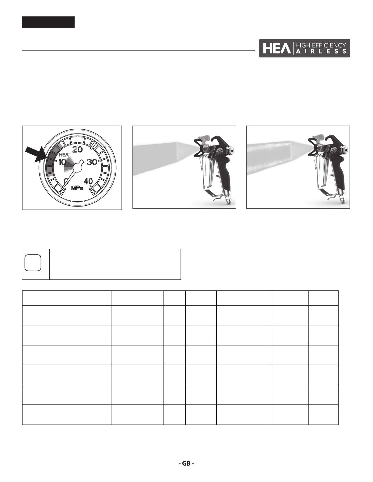
HEA stands for High Eciency Airless, an innovative nozzle technology revolutionising airless spraying. HEA nozzles allow the pressure
of the spray device to be reduced right down and allow it to work in the low-pressure range (ideally at 80 - 140 bar). The nozzles can
be used with all TradeTip 3 nozzle holders and WAGNER devices.
Some paints may need to be diluted to achieve the best result possible. The experts at Wagner application technology have therefore
tested a wide range of materials for you. Their recommendations can be found in the Wagner Spray Guide at sprayguide.wagnergroup.com.
Set the low pressure in the HEA range
and start.
HEA tip table
All of the tips in the table below are supplied
together with the appropriate gun lter.
Application Tip marking Spray
Synthetic-resin paints
PVC paints
Paints, primers
Fillers
Fillers
Rust protection paints
Rust protection paints
Latex paints
Dispersions
Rust protection paints
Latex paints
Dispersions
Flame retardant 421
211
311
411
213
313
413
415
515
615
417
517
617
519
619
521
621
Even spray pattern without spray edges.
angle
20°
30°
40°
20°
30°
40°
40°
50°
60°
40°
50°
60°
50°
60°
40°
50°
60°
Bore
inch / mm
0.011 / 0.28
0.011 / 0.28
0.011 / 0.28
0.013 / 0.33
0.013 / 0.33
0.013 / 0.33
0.015 / 0.38
0.015 / 0.38
0.015 / 0.38
0.017 / 0.43
0.017 / 0.43
0.017 / 0.43
0.019 / 0.48
0.019 / 0.48
0.021 / 0.53
0.021 / 0.53
0.021 / 0.53
Spraying
width mm 1)
120
150
190
120
150
190
190
225
270
190
225
270
225
270
190
225
270
If edges are visible, slowly increase the
pressure.
Gun lter Order no.
red
red
Rot
red
red
red
yellow
yellow
yellow
white
white
white
white
white
white
white
white
0554211
0554311
0554411
0554213
0554313
0554413
0554415
0554515
0554615
0554417
0554517
0554617
0554519
0554619
0554421
0554521
0554621
1) Spray width at about 30 cm to the object and 100 bar (10 MPa) pressure with synthetic-resin paint 20 DIN seconds.
29
Page 30

SPARE PARTS DIAGRAM CUADRO DE PIEZAS DE RECAMBIO
DIAGRAMA DAS PEÇAS SOBRESSELENTES
GB ACCESSORIES DIAGRAM E CUADRO DE ACCESORIOS
P DIAGRAMA DAS ACESSÓRIOS
2
1
5
ProSpray 20
10
3
4
8
9
7
6
86
Page 31

ProSpray 20
# PS 20 Description Denominación Descrição
1 0538 041 Spray gun, Vector Pro 2-nger Pistola de pulverización Vector Pro 2 dedos Pistola de pulverização Vector Pro 2 dedos
0538 040 Spray gun, Vector Pro 4-nger Pistola de pulverización Vector Pro 4 dedos Pistola de pulverização Vector Pro 4 dedos
0538 042 Spray gun, Vector Grip 2-nger Pistola de pulverización Vector Grip 2
0538 043 Spray gun, Vector Grip 4-nger Pistola de pulverización Vector Grip 4
2 0296 441 Pole gun 120 cm, G-thread 7/8” Pistola con alargadera 120 cm, rosca G, 7/8” Pistola com vara 120 cm, rosca G 7/8”
0296 443 Pole gun 120 cm, F-thread 11/16” Pistola con alargadera 120 cm, rosca F,
0296 442 Pole gun 200 cm, G-thread 7/8” Pistola con alargadera 200 cm, rosca G, 7/8” Pistola com vara 200 cm, rosca G 7/8”
0296 444 Pole gun 200 cm, F-thread 11/16” Pistola con alargadera 200 cm, rosca F,
3 0345 010 In-line roller IR-100 Rodillo In-line IR-100 Rolo In-line IR-100
4 9984 573 High-pressure hose DN 4 mm, 7.5 m with
stainless steel nipple, 1/4”
9984 574 High-pressure hose DN 6 mm, 15 m for
dispersion, 1/4”
9984 575 High-pressure hose DN 6 mm, 30 m for
dispersion, 1/4”
5 0034 038 Double socket for coupling high-pressure
hoses (1/4” x 1/4”)
6 0034 950 Metex-Reuse
Reuse for pre-ltering of coating material in
vessel. Place suction pipe in the reuse.
0034 952 Sieve package (5 pcs) for paint Paquete de tamices (5 piezas) para laca Embalagem de tamis (5 peças) para tinta
0034 951 Sieve package (5 pcs) for dispersion Paquete de tamices (5 piezas) para pinturas
7 0034 383 Gun lter, red, 1 piece; 180 mesh extra ne Filtro de pistola, rojo, 1 unidad, malla 180
0097 022 Gun lter, red, 10 pieces; 180 mesh extra
ne
0043 235 Gun lter, yellow, 1 piece; 100 mesh ne Filtro de pistola, amarillo, 1 unidad, malla
0097 023 Gun lter, yellow, 10 pieces; 100 mesh ne Filtro de pistola, amarillo, 10 unidades,
0034 377 Gun lter, white, 1 piece; 50 mesh medium Filtro de pistola, blanco, 1 unidad, malla 50
0097 024 Gun lter, white, 10 pieces; 50 mesh
medium
0089 323 Gun lter, green, 1 piece; 30 mesh coarse Filtro de pistola, verde, 1 unidad, malla 30
0097 025 Gun lter, green, 10 pieces; 30 mesh coarse Filtro de pistola, verde, 10 unidades, malla
8 0097 108 TipClean Cleaning Set for easy cleaning and
conservation of nozzles
0508 619 EasyGlide, special oil (118ml) EasyGlide, aceite especial (118ml) EasyGlide, óleo especial (118 ml)
0508 620 EasyClean, cleaning and conservation
agent (118 ml)
9 0551 969 Hopper kit Conjunto de la tolva Conjunto do funil de carga
10 2312 909 Personel protection switch (PRCD) 230V /
16A (3 m)
dedos
dedos
11/16”
11/16”
Manguera de alta presión DN 4 mm, 7,5 m
con racor de acero inoxidable, 1/4”
Manguera de alta presión DN 6 mm, 15 m
para pinturas de dispersión, 1/4”
Manguera de alta presión DN 6 mm, 30 m
para pinturas de dispersión, 1/4”
Pieza de unión para acoplamiento de
mangueras de alta presión (1/4” x 1/4”)
Metex-Reuse
Reuse para el ltrado previo del material de
recubrimiento en el envase. Poner el tubo
de aspiración directamente el Reuse.
de dispersión
extra ne
Filtro de pistola, rojo, 10 unidades, malla
180 extra ne
100 ne
malla 100 ne
medium
Filtro de pistola, blanco, 10 unidades, malla
50 medium
coarse
30 coarse
Kit de limpieza TipClean para limpieza fácil
y conservación de boquillas
EasyClean, agente de conservación y
limpieza (118 ml)
Interruptor de protección personal (fusible
FI) 230V / 16A
Pistola de pulverização Vector Grip 2 dedos
Pistola de pulverização Vector Grip 4 dedos
Pistola com vara 120 cm, rosca F 11/16”
Pistola com vara 200 cm, rosca F 11/16”
Tubo exível de alta pressão DN 4 mm, 7,5
m com bocal de aço inoxidável, 1/4”
Tubo exível de alta pressão DN 6 mm, 15
m para dispersão, 1/4”
Tubo exível de alta pressão DN 6 mm, 30
m para dispersão, 1/4”
Junção dupla para acoplar tubos exíveis
de alta pressão (1/4” x 1/4”)
Metex-Reuse
Reuse para a pré-ltração do material de
revestimento num repiciente. Colocar o
tubo de sucção no Reuse.
Embalagem de tamis (5 peças) para
dispersão
Filtro da pistola, vermelho, 1 peça; Malha
180 extra na
Filtro da pistola, vermelho, 10 peças; Malha
180 extra na
Filtro da pistola, amarelo, 1 peça; Malha
100 na
Filtro da pistola, amarelo, 10 peças; Malha
100 na
Filtro da pistola, branco, 1 peça; Malha 50
média
Filtro da pistola, branco, 10 peças; Malha
50 média
Filtro da pistola, verde, 1 peça; Malha 30
grossa
Filtro da pistola, verde, 10 peças; Malha 30
grossa
Conjunto de Limpeza TipClean para uma
limpeza fácil e conservação das boquilhas
EasyClean, agente de limpeza e
conservação (118 ml)
Interruptor de protecção pessoal (PRCD)
230V / 16A (3 m)
87
Page 32

SPARE PARTS DIAGRAM CUADRO DE PIEZAS DE RECAMBIO
13
CEE 7/7
BS4343
DIAGRAMA DAS PEÇAS SOBRESSELENTES
GB MAIN ASSEMBLY E CONJUNTO PRINCIPAL
P CONJUNTO PRINCIPAL
14
1
15
16
17
18
ProSpray 20
30
0532 253
~110V
6 m
0558 465
220V-240V~
6 m
3
31
32
2
3
4
5
39
6
7
8
9
36
37
38
10
11
12
19
20
21
22
23
24
25
26
27
28
88
4
33
34
35
29
Page 33

ProSpray 20
# PS 20 Description Denominación Descrição
1 0552 300 Motor shroud Cubremotor Cobertura do motor
2 9805 287 Screw (4) Tornillo (4) Parafuso (4)
3 0558 555 Power cord jumper Cable de conexión Cabo de alimentação
4 0551 714 Cord grip (2) Pinza de contacto (2) Fixador do cabo (2)
5 9800 340 Ground screw Tierra el tornillo Parafuso de ligação à terra
6 0509 218 Screw (4) Tornillo (4) Parafuso (4)
7 0522 143A Motor control assembly Tapa del disipador de calor Cobertura do dissipador de calor
8 0507 751 Grommit Clavija Tampão da entrada
9 0509 550 Screw (4) Tornillo (4) Parafuso (4)
10 03662 Microswitch insulator Aislante de micro-interruptor Isolador do microinterruptor
11 0522 633 Microswitch Micro-interruptor Microinterruptor
12 9800 604 Screw (2) Tornillo (2) Parafuso (2)
13 0509 219 Screw Tornillo Parafuso
14 0551 513 Knob Mando regulador de presión Botão regulador da pressão
15 0551 522 Knob housing Caja de perilla Corpo do botão
16 9822 522 Retaining ring Anillo de jación Anel de retenção
17 02712 Spring Resorte Mola do botão
18 0551 521 Plunger Contacto de presión Êmbolo
19 ------- Drive assembly Conjunto del macanismo impulsor Unidade de comando
20 0509 218 Screw (4) Tornillo (4) Parafuso (4)
21 0551 518 Face plate Tapa frontal Tampa frontal
22 0558 263A Fluid section assembly Conjunto de la zona de pintura Secção de uido
23 0507 931 Cam base Base de la leva Base de came
24 5006 543 Groove pin Pasador de ranura Pino entalhado
25 0507 662 Relief valve knob Manilla de la válvula Manípulo da válvula
26 730-197 Cap Tapón Tampão
27 193-200 Return tube tting Acople del tubo de retorno Conexão do tubo de retorno
28 0508 553 Screw (2) Tornillo (2) Parafuso (2)
29 0508 239 Manometer Manómetro Manómetro
30 0558 672A Siphon assembly Sistema de aspiración Sistema de sucção
31 -------- Power cord Cable de conexión Cabo de alimentação
32 275703 Cord grip Pinza de contacto Fixador do cabo
33 0509 218 Screw (4) Tornillo (4) Parafuso (4)
34 9800 340 Ground screw (2) Tierra el tornillo (2) Parafuso de ligação à terra (2)
35 0558 452 Bracket cover Cubierta del soporte Tampa do suporte de montagem
36 0558 449 Bracket Soporte Suporte de montagem
37 0551 980 Lock nut (2) Contratuerca (2) Contraporca (2)
38 0522 424 EMI lter, 20A Filtro EMI, 20A Filtro EMI, 20A
39 2406054 Washer, nylon
Arandela, nylon Arruela, nylon
89
Page 34

SPARE PARTS DIAGRAM CUADRO DE PIEZAS DE RECAMBIO
DIAGRAMA DAS PEÇAS SOBRESSELENTES
GB FLUID SECTION E ZONA DE PINTURA
P SECÇÃO DE FLUIDO
1
2
ProSpray 20
10
11
12
13
14
15
3
4
5
6
7
8
9
23
24
25
26
90
16
17
18
19
20
21
22
Page 35

ProSpray 20
# PS 20 Description Denominación Descrição
1 0509 594 Retainer Tuerca guía
2 0509 584 Piston guide Guía de pistón
3 ------- Upper packing Empaquetadura superior
4 0551 112 Transducer assembly Impulsor manométrico Conjunto do transdutor
5 806-106 Pump manifold Caja de escala cromática
6 0509 873 Fitting Pieza de unión
7 0507 690 Bypass valve assembly Conjunto de válvula de derivación Conjunto da válvula de desvio
8 0507 745 Gasket Empaquetadura Junta
9 ------- Lower packing Empaquetadura inferior
10 0290 277A Piston rod Pistón
11 704-610 Upper cage Guía de bola superior
12 0551 263 Crush washer Arandela Arruela
13 0516 303 Outlet valve ball Bola de válvula de escape
14 0551 620 Outlet valve seat Encaje de válvula de escape
15 13481 Outlet valve retainer Caja de válvula de escape
16 0509590 Bushing Manguito
17 0509 581 Inlet valve seal Junta inferior
18 0509 591 Lower ball guide Guía de bola inferior
19 0509 583 Inlet valve ball Bola de válvula de admisión
20 0551 534 Inlet valve seat Encaje de válvula de admisión
21 0509 582 O-ring, PTFE Anillo tórico, PTFE
22 0508 680 Inlet valve housing Caja de válvula de admisión
23 0516 775 Filter housing Caja de ltro Corpo da ltro
Porca de xação
Guia do pistão
Empanque superior
Colector da bomba
Junção dupla
Empanque inferior
Pistão
Guia de esfera superior
Esfera da válvula de escape
Sede da válvula de escape
Corpo da válvula de escape
Bucha
Vedação inferior
Guia de esfera inferior
Esfera da válvula de admissão
Sede da válvula de admissão
Anel em O
Corpo da válvula de admissão
, PTFE
24 0515 252 Filter Filtro Filtro
25 0296 289 O-ring Anillo tórico
26 0507 517 Pipe plug Tapón de la tubería Tampão do tubo
0509 151 Piston assembly (includes items 10-15) Conjunto de pistón (incluye los
0551 533 Repacking kit (includes items 2-3, 9,
11, 13, 17, 19 and 21).
91
elementos 10 a 15)
Juego para volver a colocar la
empaquetadura (incluye los
elementos 2 a 3, 9, 11, 13, 17, 19 y 21).
Anel em O
Conjunto do pistão (inclui os itens
10-15)
Kit de novos empanques (inclui os
itens 2-3, 9, 11, 13, 17, 19 e 21).
Page 36

SPARE PARTS DIAGRAM CUADRO DE PIEZAS DE RECAMBIO
1
ProSpray 20
DIAGRAMA DAS PEÇAS SOBRESSELENTES
GB DRIVE ASSEMBLY E CONJUNTO DEL MECANISMO IMPULSOR
P UNIDADE DE COMANDO
2
3
4
5
9
10
8
6
7
# PS 20 Description Denominación Descrição
1 806-100A Housing assembly (includes item 9) Conjunto de carcasa (incluye le
elemento 9)
2 0508 573 Thrust washer Arandela de entrada Arruela de encosto
3 0508 572A Gear/crankshaft assembly Eje de cigüeñal
4 0509 121 2nd stage gear Rueda de engranaje, grado 2 Engrenagem de segundo andar
5 0558 314A Motor assembly, 220-240V~ Conjunto del motor, 220-240V~ Conjunto do motor, 220-240V~
0558 353A Motor assembly, 100-110V~ Conjunto del motor, 100-110V~ Conjunto do motor, 100-110V~
Conjunto do alojamento (inclui os
itens 9)
Conjunto de engrenagem/eixo de
manivela
6 9820 213 Washer (4) Arandela (4) Arruela (4)
7 9800 341 Screw (4) Tornillo (4) Parafuso (4)
8 0508 208 Slider assembly Conjunto deslizante Conjunto do mecanismo deslizante
9 9850 936 Switch Interruptor Interruptor
10 0551 991 Circuit breaker, 220-240V~ Disjuntor, 220-240V~ Disjuntor, 220-240V~
704-211A Circuit breaker, 100-110V~ Disjuntor, 100-110V~ Disjuntor, 100-110V~
92
Page 37
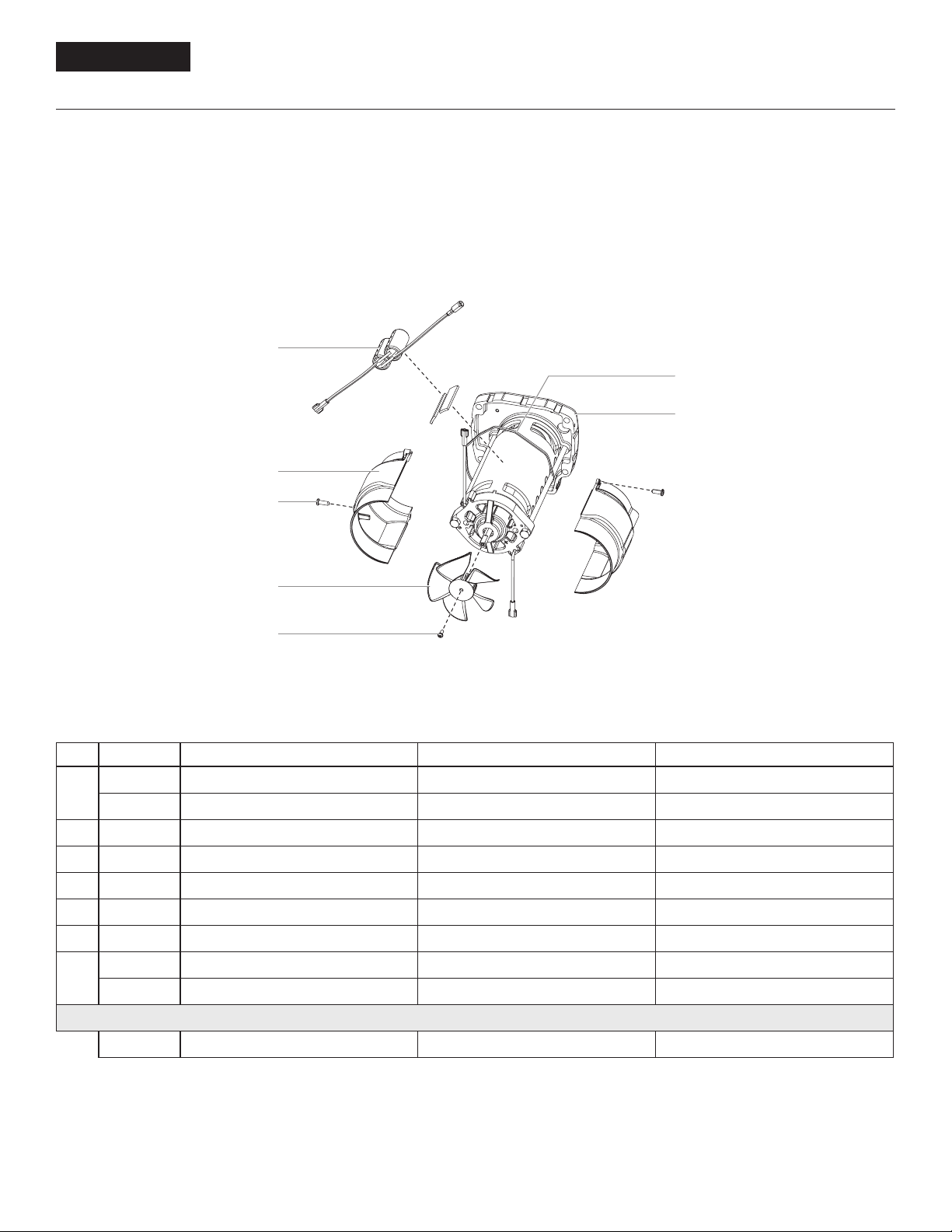
ProSpray 20
SPARE PARTS DIAGRAM CUADRO DE PIEZAS DE RECAMBIO
DIAGRAMA DAS PEÇAS SOBRESSELENTES
GB MOTOR ASSEMBLY E CONJUNTO DEL MOTOR
P UNIDADE DE MOTOR
1
6
7
2
3
4
5
# PS 20 Description Denominación Descrição
1 0551 967 Capacitor assembly, 220-240V~ Condensadores, 220-240V~ Condensador, 220-240V~
0522 100 Capacitor assembly, 100-110V~ Condensadores, 100-110V~ Condensador, 100-110V~
2 806-304 Fan shroud (2) Cubierta de ventilador (2) Cobertura do ventilador (2)
3 704-322 Screw (2) Tornillo (2) Parafuso (2)
4 806-308 Fan Ventilador Ventoinha
5 9804 916 Screw Tornillo Parafuso
6 0551 543 Tie wrap Amarre del cable Braçadeira
7 0551 174A Motor, 220-240V~ Motor, 220-240V~ Motor, 220-240V~
0551 540 Motor, 100-110V~ Motor, 100-110V~ Motor, 100-110V~
704-276 Motor brush kit Juego de escobillas de carbón Kit de escovas do motor
93
Page 38

SPARE PARTS DIAGRAM CUADRO DE PIEZAS DE RECAMBIO
DIAGRAMA DAS PEÇAS SOBRESSELENTES
GB STAND ASSEMBLY E BASTIDORSOPORTE
P ESTRUTURA
1
ProSpray 20
2
3
# PS 20 Description Denominación Descrição
1 0508 377 Cord holder Soporte de cable de red Suporte do cabo
4
5
6
7
8
9
10
11
2 806-071 Leg, left Arco a la izquierda Apoio esquerdo
3 9885 546 Plug (2) Tapón de cierre (2) Tampão (2)
4 0551 527 Screw Tornillo Parafuso
5 0509 856 Nut Tuerca Porca
6 0290 234 Leg, right Arco a la derecha Apoio direito
7 806-216 Tube clip Grapa Grampo
8 0551 434 Screw Tornillo Parafuso
9 0508 381 Drip cup Recipiente de limpieza Recipiente de gotejamento
10 9805 230 Screw Tornillo Parafuso
11 9885 546 Plug (2) Tapón de cierre (2) Tampão (2)
0551 526 Left leg assembly (includes items 1-4) Arco a la izquierda (Pos. 1-4) Apoio esquerdo (item 1-4)
0551 524 Right leg assembly (includes items
5-11)
Arco a la derecha (Pos. 5-11) Apoio direito (item 5-11)
94
Page 39

ProSpray 20
SPARE PARTS DIAGRAM CUADRO DE PIEZAS DE RECAMBIO
DIAGRAMA DAS PEÇAS SOBRESSELENTES
GB SUCTION SYSTEM E SISTEMA DE ASPIRACIÓN
P SISTEMA DE SUCÇÃO
1
3
4
5
2
# PS 20 Description Denominación Descrição
1 0558672A Siphon tube assembly (includes items
1-8)
2 0558659A Return tube Manguera de retorno Tubo de retorno
3 0279459 Clip Grapa Grampo
4 700-805 Inlet screen Filtro Filtro
5 9871105 O-ring (2) Anillo tórico (2) Anel em O (2)
704-109 O-ring (for hot solvents, optional) (2) O-ring (para solventes calientes,
Sistema de aspiración (Pos. 1-8) Sistema de sucção (Pos. 1-8)
opcional) (2)
6
8
7
Joint torique (para solventes quentes,
opcional) (2)
6 9822526 Retaining clip Grapa Grampo
7 9850638 Tie wrap Amarre del cable Braçadeira
8 0327226 Return tube clamp Grapa del tubo de retorno Grampo do tubo de retorno
95
Page 40

ProSpray 20
IMPORTANT NOTES ON PRODUCT LIABILITY
As a result of an EC regulation being eective as from January 1, 1990, the
manufacturer shall only be liable for his product if all parts come from him or
are released by him, and if the devices are properly mounted and operated.
If the user applies outside accessories and spare parts, the manufacturer´s
liability can fully or partially be inapplicable; in extreme cases usage of the
entire device can be prohibited by the competent authorities (employer´s
liability insurance association and factory inspectorate division).
Only the usage of original WAGNER accessories and spare parts guarantees
that all safety regulations are observed.
3+2 YEARS GUARANTEE FOR PROFESSIONAL FINISHING
Wagner professional guarantee
(Status 01.02.2009)
1. Scope of guarantee
All Wagner professional colour application devices (hereafter referred to as
products) are carefully inspected, tested and are subject to strict checks under
Wagner quality assurance. Wagner exclusively issues extended guarantees to
commercial or professional users (hereafter referred to as “customer”) who
have purchased the product in an authorised specialist shop, and which relate
to the products listed for that customer on the Internet under www.wagnergroup.com/pro-guarantee.
The buyer’s claim for liability for defects from the purchase agreement with the
seller as well as statutory rights are not impaired by this guarantee.
We provide a guarantee in that we decide whether to replace or repair the
product or individual parts, or take the device back and reimburse the purchase
price. The costs for materials and working hours are our responsibility. Replaced
products or parts become our property.
2. Guarantee period and registration
The guarantee period amounts to 36 months. For industrial use or equal wear,
such as shift operations in particular, or in the event of rentals it amounts to
12 months.
Systems driven by petrol or air are also guaranteed for a 12 month period.
The guarantee period begins with the day of delivery by the authorised
specialist shop. The date on the original purchase document is authoritative.
For all products bought in authorised specialist shops from 01.02.2009 the
guarantee period is extended to 24 months providing the buyer of these
devices registers in accordance with the following conditions within 4 weeks
of the day of delivery by the authorised specialist shop.
Registration can be completed on the Internet under www.wagner-group.
com/pro-guarantee. The guarantee certicate is valid as conrmation, as
is the original purchase document that carries the date of the purchase.
Registration is only possible if the buyer is in agreement with having the data
being stored that is entered during registration.
When services are carried out under guarantee the guarantee period for the
product is neither extended nor renewed.
Once the guarantee period has expired, claims made against the guarantee or
from the guarantee can no longer be enforced.
4. Exclusion of guarantee
Guarantee claims cannot be considered
- for parts that are subject to wear and tear due to use or other natural
wear and tear, as well as defects in the product that are a result of
natural wear and tear, or wear and tear due to use. This includes in
particular cables, valves, packaging, jets, cylinders, pistons, meanscarrying housing components, lters, pipes, seals, rotors, stators, etc.
Damage due to wear and tear that is caused in particular by sanded
coating materials, such as dispersions, plaster, putty, adhesives, glazes,
quartz foundation.
- in the event of errors in devices that are due to non-compliance with
the operating instructions, unsuitable or unprofessional use, incorrect
assembly and/or commissioning by the buyer or by a third party,
or utilisation other than is intended, abnormal ambient conditions,
unsuitable coating materials, unsuitable operating conditions,
operation with the incorrect mains voltage supply/frequency, overoperation or defective servicing or care and/or cleaning.
- for errors in the device that have been caused by using accessory parts,
additional components or spare parts that are not original Wagner
parts.
- for products to which modications or additions have been carried out.
- for products where the serial number has been removed or is illegible
- for products to which attempts at repairs have been carried out by
unauthorised persons.
- for products with slight deviations from the target properties, which are
negligible with regard to the value and usability of the device.
- for products that have been partially or fully taken apart.
5. Additional regulations.
The above guarantees apply exclusively to products that have been bought
by authorised specialist shops in the EU, CIS, Australia and are used within the
reference country.
If the check shows that the case is not a guarantee case, repairs are carried out
at the expense of the buyer.
The above regulations manage the legal relationship to us concludingly.
Additional claims, in particular for damages and losses of any type, which occur
as a result of the product or its use, are excluded from the product liability act
except with regard to the area of application.
Claims for liability for defects to the specialist trader remain unaected.
German law applies to this guarantee. The contractual language is German. In
the event that the meaning of the German and a foreign text of this guarantee
deviate from one another, the meaning of the German text has priority.
J. Wagner GmbH
Division Professional Finishing
Otto Lilienthal Strasse 18
88677 Markdorf
Federal Republic of Germany
3. Handling
If defects can be seen in the materials, processing or performance of the device
during the guarantee period, guarantee claims must be made immediately, or
at the latest within a period of 2 weeks.
The authorised specialist shop that delivered the device is entitled to accept
guarantee claims. Guarantee claims may also be made to the service centres
named in our operating instructions. The product has to be sent without
charge or presented together with the original purchase document that
includes details of the purchase date and the name of the product. In order
to claim for an extension to the guarantee, the guarantee certicate must be
included.
The costs as well as the risk of loss or damage to the product in transit or by the
centre that accepts the guarantee claims or who delivers the repaired product,
are the responsibility of the customer.
98
Page 41

ProSpray 20
Berlin
J. Wagner GmbH
Servicestützpunkt
Flottenstraße 28–42
13407 Berlin
T 030 - 41109386
F 030 - 41109387
Ratingen
J. Wagner GmbH
Servicestützpunkt
Siemensstraße 6-10
40885 Ratingen
T 02102 - 31037
F 02102 - 34395
Heidersdorf in Sachsen
J. Wagner GmbH
Servicestützpunkt
Olbernhauer Straße 11
09526 Heidersdorf
T 037361 - 15707
F 037361 - 15708
Kassel
J. Wagner GmbH
Servicestützpunkt
Fliederweg 3
34305 Niedenstein
T 05624 - 925537
F 05624 - 925538
München
Jahnke GmbH
Rathausstraße 13
85640 Putzbrunn
T 089 - 6140022
F 089 - 6140433
email: info@airless.de
www.airless.de
Nürnberg
Grimmer GmbH
Siemensstraße 16-18
91126 Rednitzhembach
T 09122 - 79473
F 09122 - 794750
email: info@grimmer-sc.de
www.grimmer-sc.de
Markdorf – Zentrale
J. Wagner GmbH
Otto-Lilienthal-Straße 18
88677 Markdorf
Postfach 11 20
88669 Markdorf
T 07544 - 505 - 0
F 07544 - 505-1200
www.wagner-group.com
Kundenzentrum
T 07544 - 505-1666
F 07544 - 505-1155
email: kundenzentrum@wagner-group.com
Technischer Service
T 0180 - 55924637
(14 Cent/Minute aus dem deutschen
Festnetz, Mobilfunk max. 42 Cent/Min)
WAGNER KONTAKTNETZ DEUTSCHLAND, IM INTERNET ZU FINDEN UNTER: GO.WAGNERGROUP.COM/PROFI
103
Page 42

A J. Wagner Ges.m.b.H.
Ottogasse 2/20
2333 Leopoldsdorf
Österreich
Tel. +43/ 2235 / 44 158
Telefax +43/ 2235 / 44 163
oce@wagner-group.at
DK Wagner Spraytech
Scandinavia A/S
Helgeshøj Allé 28
2630 Taastrup
Denmark
Tel. +45 43 27 18 18
Telefax +45 43 43 05 28
wagner@wagner-group.dk
GB Wagner Spraytech (UK) Limited
Innovation Centre
Silverstone Park
Silverstone
Northants NN12 8GX
Great Britain
Tel. 01327 368410
enquiries@wagnerspraytech.co.uk
B WSB Finishing Equipment
Veilinglaan 56-58
1861 Meise-Wolvertem
Belgium
Tel. +32/2/269 46 75
Telefax +32/2/269 78 45
info@wagner-wsb.nl
CH Wagner International AG
Industriestrasse 22
9450 Altstätten
Schweiz
Tel. +41/71 / 7 57 22 11
Telefax +41/71 / 7 57 22 22
wagner@wagner-group.ch
D
J. Wagner GmbH
Otto-Lilienthal-Straße 18
D-88677 Markdorf
Postfach 11 20
D-88669 Markdorf
Deutschland
Tel.: +49 / 75 44 / 505 -1664
Fax: +49 / 75 44 / 505 -1155
wagner@wagner-group.com
www.wagner-group.com
CZ E-Coreco s.r.o.
Na Roudné 102
301 00 Plzeň
Czechia
Tel. +420 734 792 823
Telefax 420 227 077 364
info@aplikacebarev.cz
E Makimport Herramientas, S.L.
C/ Méjico nº 6
Pol. El Descubrimiento
28806 Alcalá de Henares (Madrid)
Tel. 902 199 021/ 91 879 72 00
Telefax 91 883 19 59
ventas@grupo-k.es
info@grupo-k.es
F Euromair Antony
S.A.V. Ile-de-France
12-14, av. F. Sommer
92160 Antony
Tel. 01.55.59.92.42
Telefax +33 (0) 1 69 81 72 57
conseil.paris@euromair.com
F Euromair Distribution
Siège Social / S.A.V. Sud
343, bd. F. Perrin
13106 Rousset Cedex
Tel. 04.42.29.08.96
Telefax 04.42.53.44.36
conseil@euromair.com
RU OOO Мефферт Полилюкс
142407 Россия, Московская обл,
Ногинский р-н, территория
«Ногинск-Технопарк» д.14
Tel. +7 495 221 6666
Telefax +7 495 99 55 88 2
2216666@m-p-l.ru
dis@m-p-l.ru
I Wagner S.p.A.
23868 Valmadrera (Lc)
Via Santa Vecchia, 109
Italia
Tel./Fax 0341 210100 (centralino)
wagner_it_va@wagner-group.com
NL WSB Finishing Equipment BV
De Heldinnenlaan 200,
3543 MB Utrecht
Netherlands
Tel. +31/ 30/241 41 55
Telefax +31/ 30/241 17 87
info@wagner-wsb.nl
S Wagner Spraytech
Scandinavia A/S
Helgeshøj Allé 28
2630 Taastrup
Denmark
Tel. +45 43 27 18 18
Telefax +45 43 43 05 28
wagner@wagner-group.dk
wagner-group.com
104
 Loading...