


EP2105 Piston Pump
Owner’s Manual • Notice d’utilisation • Manual del Propietario
Model Numbers: |
|
0295001 |
Stand |
0508006 |
Stand w/Filter |
|
SprayTECH |
1770 Fernbrook Lane
Minneapolis, MN 55447
Technical Assistance: 1-800-292-4637
Order Entry: 1-800-443-4500
Fax: 1-800-525-9501
www.spraytechinc.com
Printed in the U. S. A. |
0202 © 2002 SprayTECH. All rights reserved. Form No. 0295994D |
Español Français English
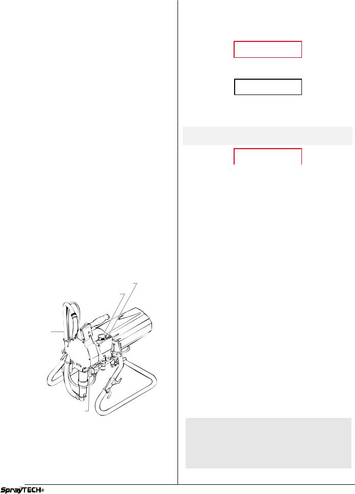
Table of Contents |
|
General Description ................................................................ |
2 |
Safety Precautions .................................................................. |
2 |
Grounding Instructions .......................................................... |
4 |
Operation ................................................................................. |
4 |
Purging and Priming.............................................................. |
4 |
Operating the Spray Gun ...................................................... |
5 |
Spraying................................................................................... |
6 |
Spraying Technique ............................................................... |
6 |
Practice.................................................................................. |
6 |
Cleanup .................................................................................... |
6 |
Flushing the Unit ................................................................... |
7 |
Maintenance ............................................................................ |
7 |
Daily Maintenance................................................................. |
7 |
Maintaining the Fluid Section ................................................ |
7 |
Cleaning the Spray Tip.......................................................... |
9 |
Cleaning the Filter ................................................................. |
9 |
Replacing the Valve Spring Unit............................................ |
9 |
Accessories ............................................................................. |
9 |
Choosing the Correct Spray Gun Filter................................. |
9 |
Troubleshooting .................................................................... |
10 |
Limited Warranty ................................................................... |
11 |
Français ................................................................................. |
12 |
Español .................................................................................. |
22 |
Parts Listings ........................................................................ |
32 |
Main Assembly .................................................................... |
32 |
Stand Assembly................................................................... |
33 |
Suction Set Assembly.......................................................... |
33 |
Drive Assembly.................................................................... |
34 |
Transducer Assembly .......................................................... |
35 |
Relay ................................................................................... |
35 |
Pressure Control Assembly ................................................. |
36 |
Fluid Section Assembly ...................................................... |
37 |
Spray Gun ........................................................................... |
38 |
Prime/Spray Valve Assembly............................................... |
38 |
Filter Assembly (optional) .................................................... |
39 |
Pressure Control Assembly Wiring Diagram ....................... |
40 |
General Description |
|
This high performance piston pump is a precision power tool used for spraying many types of materials. Read and follow this instruction manual carefully for proper operating instructions, maintenance and safety information.
ON / OFF Switch
Pressure Control Knob
Return Tube 

Suction Set
PRIME / SPRAY Knob
Safety Precautions
This manual contains information which must be read and understood before using the equipment. When you come to an area which has one of the following symbols, pay particular attention and make certain to heed the safeguard.
 WARNING
This symbol indicates a potential hazard which may cause serious injury or loss of life. Important safety information will follow.
 CAUTION
This symbol indicates a potential hazard to you or to the equipment. Important information that tells how to prevent damage to the equipment or how to avoid causes of minor injuries will follow.
NOTE: Notes give important information which should be given special attention.
 WARNING
HAZARD: Injection injury - A high pressure stream produced by this equipment can pierce the skin and underlying tissues, leading to serious injury and possible amputation. See a physician immediately.
DO NOT TREAT AN INJECTION INJURY AS A SIMPLE CUT! Injection can lead to amputation. See a physician immediately.
The maximum operating range of the gun is 3000 PSI/207BAR fluid pressure.
PREVENTION:
•NEVER aim the gun at any part of the body.
•NEVER allow any part of the body to touch the fluid stream. DO NOT allow body to touch a leak in the fluid hose.
•NEVER put your hand in front of the gun. Gloves will not provide protection against an injection injury.
•ALWAYS lock the gun trigger, shut the pump off, and release all pressure before servicing, cleaning the tip or guard, changing tip, or leaving unattended. Pressure will not be released by turning off the motor. The PRIME/SPRAY knob must be turned to PRIME to relieve the pressure. Refer to the PRESSURE RELIEF PRESSURE described in the pump manual.
•ALWAYS keep the tip guard in place while spraying. The tip guard provides some protection but is mainly a warning device.
•ALWAYS remove the spray tip before flushing or cleaning the system.
•The paint hose can develop leaks from wear, kinking and abuse. A leak can inject material into the skin. Inspect the hose before each use.
•NEVER use a spray gun without a trigger lock and trigger guard in place and in good working order.
•All accessories must be rated at or above 3000 PSI/207 BAR. This includes spray tips, guns, extensions, and hose.
NOTE TO PHYSICIAN:
Injection into the skin is a traumatic injury. It is important to treat the injury as soon as possible. DO NOT delay treatment to research toxicity. Toxicity is a concern with some coatings injected directly into the blood stream. Consultation with a plastic surgeon or reconstructive hand surgeon may be advisable.
English |
2 |
© SprayTECH. All rights reserved. |
|
|
|

HAZARD: EXPLOSION OR FIRE - Solvent and paint fumes can explode or ignite. Severe injury and/or property damage can occur.
PREVENTION:
•Provide extensive exhaust and fresh air introduction to keep the air within the spray area free from accumulation of flammable vapors.
•Avoid all ignition sources such as static electric sparks, open flames, pilot lights, and hot objects. Connecting or disconnecting power cords or working light switches can make sparks.
•Do not smoke in spray area.
•Fire extinguisher must be present and in good working order.
•Place paint pump at a minimum of 3 feet (preferably more) into a separate, well ventilated room from the spray object or at least 20 feet from the spray object in a well ventilated area (add more hose if necessary). Flammable vapors are often heavier than air. Floor area must be extremely well ventilated. The paint pump contains arcing parts that emit spark and can ignite vapors.
•The equipment and objects in and around the spray area must be properly grounded to prevent static sparks.
•Use only conductive or grounded high pressure fluid hose. Gun must be grounded through hose connections.
•Power cord must be connected to a grounded circuit.
•Always flush unit into a separate metal container, at low pump pressure, with spray tip removed. Hold gun firmly against side of container to ground container and prevent static sparks.
•Follow the material and solvent manufacturer's warnings and instructions.
•Use extreme caution when using materials with a flashpoint below 70° F (21° C). Flashpoint is the temperature that a fluid can produce enough vapors to ignite.
•Plastic can cause static sparks. Never hang plastic to enclose a spray area. Do not use plastic drop cloths when spraying flammable materials.
•Use lowest possible pressure to flush equipment.
GAS ENGINE (WHERE APPLICABLE)
Always place pump outside of structure in fresh air. Keep all solvents away from the engine exhaust. Never fill fuel tank with a running or hot engine. Hot surface can ignite spilled fuel. Always attach ground wire from pump unit to a grounded object, such as a metal water pipe. Refer to engine owner’s manual for complete safety information.
HAZARD: EXPLOSION HAZARD DUE TO INCOMPATIBLE MATERIALS - Will cause severe injury or property damage.
PREVENTION:
•Do not use materials containing bleach or chlorine.
•Do not use halogenated hydrocarbon solvents such as mildewcide, methylene chloride and 1,1,1 - trichloroethane. They are not compatible with aluminum.
•Contact your coating supplier about the compatibility of material with aluminum.
HAZARD: HAZARDOUS VAPORS - Paints, solvents, insecticides, and other materials can be harmful if inhaled or come in contact with the body. Vapors can cause severe nausea, fainting, or poisoning.
PREVENTION:
•Use a respirator or mask if vapors can be inhaled. Read all instructions supplied with the mask to be sure it will provide the necessary protection.
•Wear protective eyewear.
•Wear protective clothing as required by coating manufacturer.
HAZARD: GENERAL - This product can cause severe injury or property damage.
PREVENTION:
•Read all instructions and safety precautions before operating equipment.
•Always disconnect the motor from the power supply before working on the equipment.
•Follow all appropriate local, state, and national codes governing ventilation, fire prevention, and operation.
•The United States Government Safety Standards have been adopted under the Occupational Safety and Health Act (OSHA). These standards, particularly part 1910 of the General Standards and part 1926 of the Construction Standards should be consulted.
•Use only manufacturer authorized parts. User assumes all risks and liabilities when using parts that do not meet the minimum specifications and safety devices of the pump manufacturer.
•Before each use, check all hoses for cuts, leaks, abrasion or bulging of cover. Check for damage or movement of couplings. Immediately replace the hose if any of these conditions exist. Never repair a paint hose. Replace it with another grounded high-pressure hose.
•All hoses, swivels, guns, and accessories must be pressure rated at or above 3000PSI/207 BAR.
•Do not spray outdoors on windy days.
•Wear clothing to keep paint off skin and hair.
© SprayTECH. All rights reserved. |
3 |
English |
|
|
|
Grounding Instructions
This product must be grounded. In the event of an electrical short circuit, grounding reduces the risk of electric shock by providing an escape wire for the electric current. This product is equipped with a cord having a grounding wire with an appropriate grounding plug. The plug must be plugged into an outlet that is properly installed and grounded in accordance with all local codes and ordinances.
DANGER — Improper installation of the grounding plug can result in a risk of electric shock. If repair or replacement of the cord or plug is necessary, do not connect the green grounding wire to either flat blade terminal. The wire with insulation having a green outer surface with or without yellow stripes is the grounding wire and must be connected to the grounding pin.
Check with a qualified electrician or serviceman if the grounding instructions are not completely understood, or if you are in doubt as to whether the product is properly grounded. Do not modify the plug provided. If the plug will not fit the outlet, have the proper outlet installed by a qualified electrician.
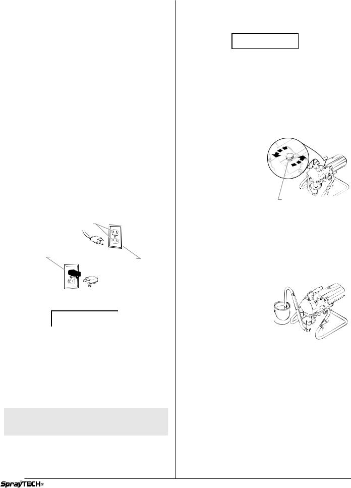
This product is for use on a nominal 120 volt circuit and has a grounding plug that looks like the plug illustrated below. A temporary adapter which looks like the adapter illustrated in the figure below may be used to connect this plug to a 2 pole receptacle as shown if a properly grounded outlet is not available.
The temporary adapter should be used only until a properly grounded outlet as shown below can be installed by a qualified electrician. The green colored rigid ear, lug, or the grounding wire extending from the adapter must be connected to a permanent ground such as a properly grounded outlet box cover. Whenever the adapter is used, it must be held in place by a metal screw.
Grounded Outlet
Grounding Pin
Cover for grounded outlet box
Metal Screw
 Adapter
 Tab for
Grounding Screw
 CAUTION
Use only a 3-wire extension cord that has a 3-blade grounding plug and a 3-slot receptacle that will accept the plug on the product. Make sure your extension cord is in good condition. When using an extension cord, be sure to use one heavy enough to carry the current your product will draw. An undersized cord will cause a drop in line voltage resulting in loss of power and overheating. A 14 or 12 gauge cord is recommended. If an extension cord is to be used outdoors, it must be marked with the suffix W-A after the cord type designation. For example, a designation of SJTW-A would indicate that the cord would be appropriate for outdoor use.
NOTE: Do not use more than 50 feet of extension cord. If you need to paint further than 100 feet from your power source, use more paint hose, not more extension cord.
Operation
Purging and Priming
 CAUTION
Always keep the spray gun locked in the off position while purging the system.
If this unit is new, it is shipped with test fluid in the fluid section to prevent corrosion during shipment and storage. If you are going to spray with latex paint, this fluid must be thoroughly cleaned out of the system. For spraying with solvent-based paint, thorough cleaning of this material is not necessary.
If it is already in service, you will need to purge the water or solvent used in cleanup.
Purging and Priming the Pump for Latex Paint
1.Secure the return hose into a waste container.
2.Place a bucket of soapy water under the suction tube.
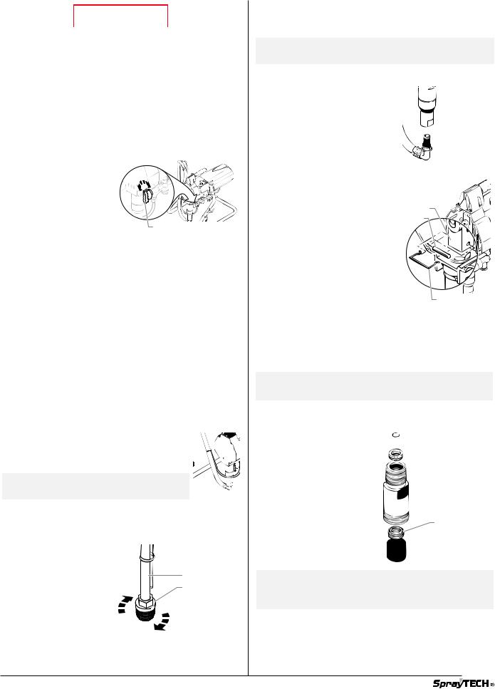
3. |
Turn the pressure control |
|
|
knob fully counterclockwise |
|
|
to reduce the pressure to |
|
|
its lowest setting. |
|
4. |
Set the PRIME/SPRAY |
|
|
valve to PRIME. |
|
5. |
Turn the ON/OFF switch to |
|
|
ON. |
|
6. |
Slowly turn the pressure |
Pressure Control Knob |
|
control knob clockwise to |
increase the pressure until fluid starts to come out of the return hose. Use only enough pressure to keep the fluid coming out.
7.Turn the pressure control knob fully counterclockwise to its lowest setting when the test fluid is purged and soapy water is coming out of the return hose.
8.Remove the bucket of soapy water from the suction tube and replace it with a bucket of clear water.
9.Increase the pressure to the minimum necessary to keep fluid flowing until clear water is coming out of the return hose.
10.Turn the pressure control knob fully counterclockwise to its lowest setting.
11. Remove the bucket of water from under the suction tube and replace it with a container of latex paint.
12. Increase the pressure slowly until paint is coming through the return hose.
13.Remove the return hose from the waste container and
place it in its operating position above the container of latex paint.
14.Keep circulating the paint through the system until the paint coming out of the return hose is free of air bubbles.
15.Turn the pressure control knob fully counterclockwise to its lowest setting.
The pump is now purged. Skip to Purging and Priming the
Spray Hose.
English |
4 |
© SprayTECH. All rights reserved. |
|
|
|
Purging and Priming for Solvent-Based Paint
Thorough cleaning is not necessary when using solvent-based paint. All you need to do is purge the test fluid from the system.
1.Secure the return hose into a waste container.
2.Place a full container of paint under the suction tube.
3.Turn the pressure control knob fully counterclockwise to reduce the pressure to its lowest setting.
4. Set the PRIME/SPRAY
valve to PRIME.
5. Turn the ON/OFF switch to ON.
6. Slowly turn the pressure control knob clockwise to increase the pressure until fluid starts to come
out of the return hose.
Use only enough pressure to keep the fluid coming out.
7.Turn the pressure control knob fully counterclockwise to its lowest setting when the test fluid is purged and paint is coming out of the return hose.
8.Remove the return hose from the waste container and place it in its operating position above the container of solvent-based paint.
9.Keep circulating the paint through the system until the paint coming out of the return hose is free of air bubbles.
10.Turn the pressure control knob fully counterclockwise to its lowest setting.
The pump is now purged. Skip to Purging and Priming the
Spray Hose.
Purging and Priming the Spray Hose
After the pump is purged and primed, you must do the same for the spray hose.
NOTE: Make certain that the spray gun has no tip installed.
 WARNING
If a metal container is used, ground the gun by holding it against the edge of the container while flushing. Failure to do so may lead to a static electric discharge which may cause a fire.
1. Turn the pressure control knob fully counterclockwise
to its lowest setting.
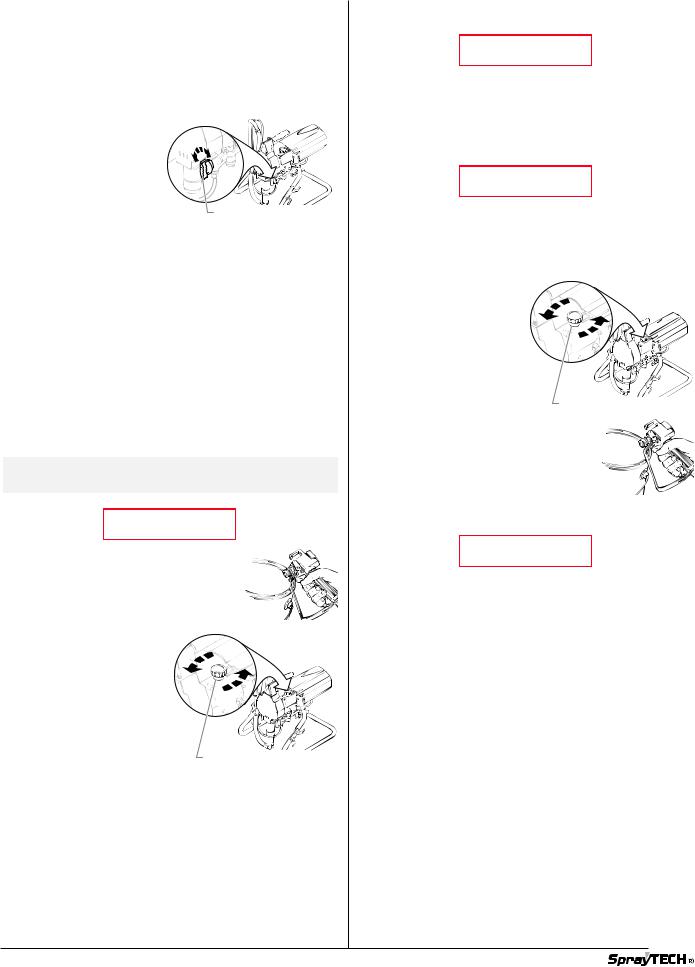
2. Set the PRIME/SPRAY
knob to SPRAY. 3. Unlock the spray gun.
4. Turn the pressure control knob slowly clockwise to increase pressure.
5. Trigger the gun into a
waste container until all air, water or solvent is purged from the spray hose and paint is flowing freely.
6.Turn the pressure control knob fully counterclockwise to its lowest setting.
7.Set the PRIME/SPRAY knob to PRIME and trigger the gun into the waste container to be sure that no pressure is left in the hose.
8.Lock the spray gun off.
Operating the Spray Gun
 WARNING
POSSIBLE INJECTION HAZARD. Do not spray without the tip guard in place. Never trigger the gun unless the tip is in either the spray or the unclog position. Always engage the gun trigger lock before removing, replacing or cleaning tip.
Pressure Relief Procedure
 WARNING
Be sure to follow the pressure relief procedure when shutting the unit down for any purpose, including servicing or adjusting any part of the spray system, changing or cleaning spray tips, or preparing for cleanup.
1.Lock the gun by turning the gun trigger lock to the locked position.
2. Turn the motor off.
3. Turn the pressure control
knob counterclockwise to its lowest setting.
4. Turn the PRIME/SPRAY knob to PRIME.
5. Unlock the gun by turning the gun trigger lock to the
unlocked position.
Pressure Control Knob
6. Hold the metal part of the gun firmly to the side of a metal container to ground the gun and avoid a build up of static electricity.
7. Trigger the gun to remove any pressure that may still be in the hose.
8.Lock the gun by turning the gun trigger lock to the locked position.
 WARNING
POSSIBLE INJECTION HAZARD. Do not spray without the tip guard in place. Never trigger the gun unless the tip is in either the spray or the unclog position. Always engage the gun trigger lock before removing, replacing or cleaning tip.
© SprayTECH. All rights reserved. |
5 |
English |
|
|
|
Spraying
NOTE: When spraying block filler, mastics or high solid coating, leave out the gun filter and high pressure filter screens.
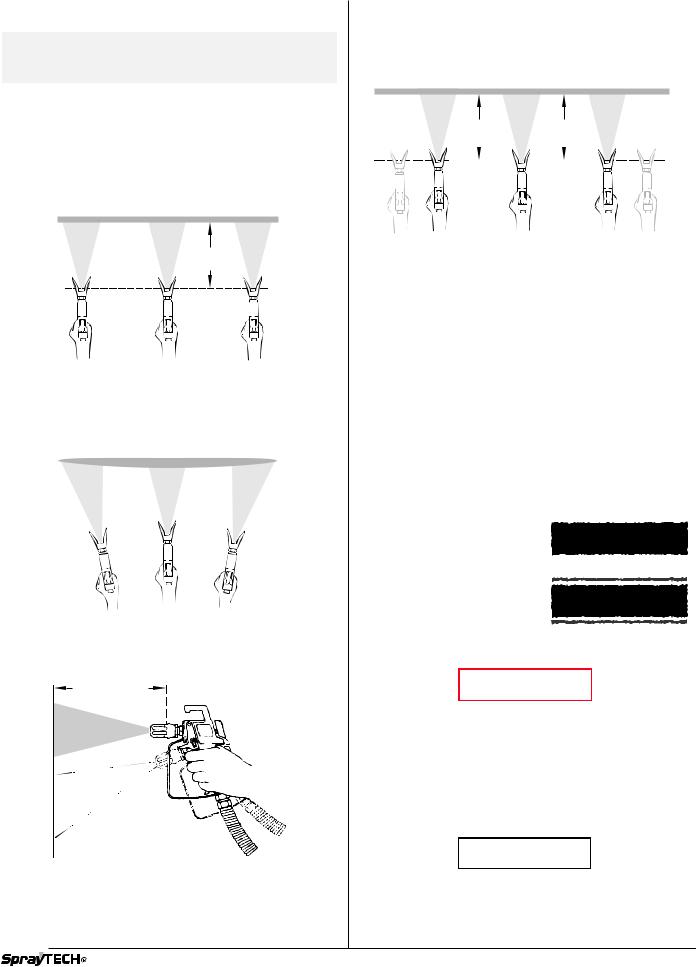
Spraying Technique
The key to a good paint job is an even coating over the entire surface. This is done by using even strokes. Keep your arm moving at a constant speed and keep the spray gun at a constant distance from the surface. The best spraying distance is 10 to 12 inches between the spray tip and the surface.
Even coat throughout
Approximately 10 to 12 inches
Keep stroke smooth and at an even speed.
Keep the spray gun at right angles to the surface. This means moving your entire arm back and forth rather than just flexing your wrist.
Light Coat |
Heavy Coat |
Light Coat |
Do not flex wrist while spraying.
Keep the spray gun perpendicular to the surface, otherwise one end of the pattern will be thicker than the other.
Approximately
10 to 12 inches
Right way
Wrong way 
The spray gun should be triggered by turning it on and off with each stroke. This will save paint and avoid paint buildup at the end of the stroke. Do not trigger the gun during the middle of a stroke. This will result in an uneven spray and splotchy coverage.
Proper way to trigger the spray gun
Keep stroke |
|
|
|
Approximately |
||||||||||||||||||
|
|
even |
|
|
|
10 to 12 inches |
||||||||||||||||
|
|
|
|
|
|
|
|
|
|
|
|
|
|
|
|
|
|
|
|
|
|
|
|
|
|
|
|
|
|
|
|
|
|
|
|
|
|
|
|
|
|
|
|
|
|
Start stroke |
Pull trigger |
Keep steady |
Release trigger End stroke |
Overlap each stroke by about 30%. This will ensure an even coating.
When you stop painting, lock the gun trigger lock, turn the pressure control knob counterclockwise to its lowest setting and set the PRIME/SPRAY valve to PRIME. Turn the motor switch to OFF and unplug the sprayer.
Practice
1.Be sure that the paint hose is free of kinks and clear of objects with sharp cutting edges.
2.Turn the pressure control knob counterclockwise to its to its lowest setting.
3.Turn the PRIME/SPRAY valve to SPRAY.
4.Turn the pressure control knob clockwise to its highest setting. The paint hose should stiffen as paint begins to flow through it.
5.Unlock the gun trigger lock.
6.Trigger the spray gun to bleed air out of the hose.
7.When paint reaches the spray tip, spray a test area to check the spray pattern.
8.Use the lowest pressure setting necessary to get a good spray pattern. If the
pressure is set too high, the |
Good spray pattern |
spray pattern will be too light. |
|
If the pressure is set too low, |
|
tailing will appear or the paint |
|
will spatter out in gobs rather |
|
than in a fine spray. |
Paint tailing pattern |
|
Cleanup
 WARNING
Special cleanup instructions for use with flammable solvents:
•Always flush spray gun preferably outside and at least one hose length from spray pump.
•If collecting flushed solvents in a one gallon metal container, place it into an empty five gallon container, then flush solvents.
•Area must be free of flammable vapors.
•Follow all cleanup instructions.
 CAUTION
The pump, hose, and gun should be cleaned thoroughly after daily use. Failure to do so permits material to cake, seriously affecting the performance of the unit.
English |
6 |
© SprayTECH. All rights reserved. |
|
|
|
 WARNING
Always spray at minimum pressure with the gun nozzle tip removed when using mineral spirits or any other solvent to clean the pump, hose, or gun. Static electricity buildup may result in a fire or explosion in the presence of flammable vapors.
Flushing the Unit
Flush the unit with the solvent appropriate to the material being used after daily use (use solvents at room temperature). The unit should then be flushed again with mineral spirits.
For long term storage, flush the unit with an appropriate oil before storing.
1.Follow the pressure relief procedure found earlier in this manual.
2. Turn the PRIME/SPRAY valve to SPRAY to bleed off any pressure remaining in the pump.
3. Remove the gun tip and |
|
clean with a solution |
|
appropriate to the type of |
|
material being sprayed. |
PRIME/SPRAY Valve |
4.Remove the material
container and replace it with a container of solvent appropriate to the type of material being sprayed.
5.Check to be sure the pressure control knob is turned fully counterclockwise to its lowest setting.
6.Turn the power switch to ON.
7.Trigger the spray gun into a waste container until solvent comes out and the pump, hose, and gun are clean.
8.Follow the pressure relief procedure found earlier in this manual.
9.Make certain that the power switch is turned to OFF.
10.Turn the PRIME/SPRAY valve to SPRAY to bleed off any remaining solvent.
11.Unplug the unit and store in a clean, dry area.
Maintenance
Daily Maintenance
Perform the following procedures daily.
Filling the Packing Nut Reservoirs With Oil
Before you start to spray each day, squirt a 


 lubricant such as hydraulic oil into the slots in the


 upper pump housing. Household oil and cooking

 oil also work when hydraulic oil is not available.


NOTE: Do not apply so much that it overflows and drips into the paint.
This lubricant keeps the piston seals pliant, minimizing paint bypass and piston wear. If the unit is operated several hours a day, lubricate approximately every 4 hours.
Cleaning the Intake Screen |
|
1. Remove the intake |
|
screen and clean with a |
|
solvent appropriate to |
|
the type of material |
Suction Set |
being used. |
Intake Screen |
|
Maintaining the Fluid Section
Servicing the fluid section includes replacing the T-lip packings, the piston, and valve parts that show signs of wear.
NOTE: If any parts are difficult to disassemble, soak them in an appropriate solvent until the paint softens.
Removing the Fluid Section
1.Using a flat blade screwdriver, pry the retaining ring out of the bottom of the inlet valve housing and remove the suction set assembly.
2.Unscrew the fluid hose from the fluid section assembly.
3.Loosen and turn the return line fitting away from the fluid section assembly.
4.Unscrew the 6 screws holding the cover to the front of the pump housing and remove the cover.
5.Pull the retaining clip from the yoke and pin.
6.Push the pin out of the piston and yoke. Use the short end of a hex wrench if necessary.
7.Loosen the locknut at the top of the fluid section assembly.
8.Unscrew the fluid section assembly from the pump.
 Inlet Valve
Housing

 Retaining
Ring
Yoke
Pin
Retaining Clip
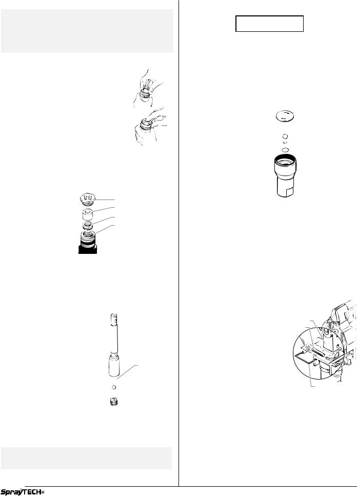
Maintaining the T-lip Packings
Removing the T-lip Packings
1.Place the wrench flats of the inlet valve housing into a vise and unscrew the fluid section from the inlet valve housing.
2.Unscrew the packing nut from the fluid section.
NOTE: When removing the piston, keep the piston from falling or the piston may be damaged.
3.Push the piston out through the lower end of the fluid section. Tap the top of the piston with a rubber mallet if necessary.
4.Remove the upper and lower spacers from the fluid section.
5.Push the T-lip packings out of the fluid section with a screwdriver. To push out the upper seal, insert the screwdriver through the lower end of the fluid section. To push out the lower seal, insert the screwdriver through the upper end of the fluid section.
 Upper Spacer
 Upper T-lip
Packing
 Fluid Section
Cylinder
Lower T-lip
Packing
 Lower Spacer
NOTE: When removing the T-lip packings, be careful not to scrape or gouge the inside surface of the fluid section with the screwdriver.
© SprayTECH. All rights reserved. |
7 |
English |
|
|
|
Replacing the T-lip Packings
NOTE: For maximum lower T-lip packing life, use a packing guide tool (see fluid section parts list for part number) to insert the lower T-lip packing into the cylinder. If you do not have a packing guide tool, follow steps 1 – 2 of the procedure below.
1.Apply a light coat of household oil to the new lower T-lip packing and insert it edge-first into the lower end of the fluid section.
2. Turn the T-lip packing inside the fluid section cylinder so that the springs of the T-lip packing face into the cylinder. To do this, hold the lower edge of the T-lip packing in place while pressing the upper edge further into the cylinder.
3. Push the lower T-lip packing as far into the fluid section as it will go.
4. Insert the lower spacer into the fluid section.
5.Apply a light coat of household oil to the
new upper T-lip packing and place it into the upper end of the fluid section. Position the T-lip packing so that it is level and the springs of the T-lip packing face into the cylinder.
6.Thread the packing nut into the fluid section to push the upper T-lip packing farther into the cylinder, then remove the packing nut.
7. |
Insert the upper |
Packing Nut |
|
|
spacer into the fluid |
||
|
Upper Spacer |
||
|
section. |
||
|
|
||
8. |
Push the upper spacer |
Upper T-lip Packing |
|
|
as far into the fluid |
Fluid Section |
|
|
section as it will go. |
||
|
Cylidner |
||
9. |
Screw the packing nut |
||
|
into the fluid section.  Torque to 25-30 ft./lbs.
Maintaining the Valves
Replacing the Piston and Worn Parts of the Outlet Valve
1.Turn the piston upside down and use a hex wrench to remove the piston seat retainer from the lower end of the piston.
2.Cover the open end of the piston and turn the piston rightside up again to remove the outlet ball seat and outlet ball.
3.Insert a new outlet ball guide into the new piston. The open end of the ball guide should face the open end of the piston. Use the head of a long nail or screw to seat the ball guide past the threads inside the piston if necessary.
4.Insert a new outlet ball into the outlet ball guide.
5.Check the outlet ball seat for wear. If both sides are worn, insert a new ball seat into the piston on top of the ball. If only one side of the ball seat is worn, insert it into the piston with the worn side facing away from the ball.
 Piston
Outlet Ball
Guide
 Outlet Ball
 Outlet Ball
Seat
 Piston Seat
Retainer
6.Apply an appropriate thread-locking compound to the threads of the piston seat retainer.
NOTE: Do not put the new piston into a vise. Putting the piston into a vise may damage the piston.
7.Screw the piston seat retainer into the lower end of the piston. Torque the retainer to 12 ft./lbs.
 CAUTION
Do not torque the piston seat retainer more than 12 ft./lbs. Over-torquing may damage the ball guide and prevent normal operation of the pump.
8.Apply a light coat of household oil to the piston and insert it, shaft first, into the lower end of the fluid section until it seats. Tap the bottom of the piston gently with a rubber mallet if necessary.
Replacing Worn Parts of the Inlet Valve
1. Remove the O-ring from the inlet valve housing.
2.Cover the top of the inlet valve housing and turn it upside down to remove the inlet ball stop disk, inlet ball guide, inlet ball, inlet ball seat, and inlet ball seal.
3.Insert a new inlet ball seal into the inlet valve housing.
4.Check the inlet ball seat for wear. If both sides are worn, insert a new ball seat into the housing. If only one side of the ball seat is worn, insert it into the housing with the worn side facing down.
 O-Ring


 Ball Stop Plate
 Inlet Ball Guide
 Inlet Ball
 Inlet Ball Seat
 Inlet Ball Seal
 Inlet Valve
Housing
5.Place a new inlet ball on the inlet ball seat in the housing.
6.Place the inlet ball guide over the inlet ball.
7.Place the inlet ball stop plate over the ball guide.
8.Insert a new O-ring into the inlet valve housing.
9.Place the wrench flats of the inlet valve housing into a vise and screw the fluid section into the inlet valve housing. Torque the inlet valve housing to 85-95 ft./lbs.
Attaching the Fluid Section
1.Turn the locknut on the fluid section until it reaches the bottom of the threads.
2.Thread the fluid section into the pump housing.
3.Rotate the fluid section to align the hole in the piston shaft with the holes in the yoke.
4.Insert the pin through the yoke and piston.
5.Snap the retaining clip around the pin and yoke.
6.Screw the fluid section into the pump housing as far as it will go, then unscrew it slightly so that the fluid hose fitting will align with the fluid hose.
7.Firmly tighten the locknut at the top of the fluid section assembly against the pump housing using an adjustable wrench.
8.Tighten the return line fitting back to its original position.
Yoke
Pin
Retaining Clip
9.Fill the reservoirs in the packing nut with hydraulic oil.
10.Replace the pump housing cover and screw in the 6 screws that hold it in place.
11.Tighten the fluid hose onto the fluid hose fitting on the fluid section.
12.Insert the elbow on the suction set assembly into the bottom of the inlet valve housing.
13.Push the retaining ring up into the groove inside the inlet valve housing to secure the suction set assembly in position.
English |
8 |
© SprayTECH. All rights reserved. |
|
|
|
Cleaning the Spray Tip
1.Flush the gun with solvent immediately after the work is completed.
2.Oil the sliding pins to prevent them from seizing up.
Should the spray tip become clogged, reverse the spray tip with the lever and pull the trigger. Once the obstruction comes out of the spray tip, release the trigger, reverse the spray tip back to the spray pattern setting, and resume spraying.
 WARNING
Do not attempt to clean the tip with your finger.
Do not use a needle or other sharp pointed instrument to clean the tip. The hard tungsten carbide is brittle and can be chipped.
Cleaning the Filter
Clean the filter with a brush dipped in solvent. Never poke the filter with a sharp instrument.
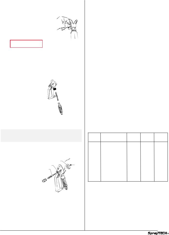
Changing the Filter
1.Pull the trigger guard forward so that it comes loose from the handle.
2.Unscrew the handle from the housing and remove the old filter.
3.Slide the new filter, taper end first, into the gun housing.
4.Replace the handle, washer and spring. Screw the handle into the housing until handtight. Replace the trigger guard.
 Gun Housing


 Filter

 Handle
Replacing the Valve Union Assembly
NOTE: Replace the packing if the spray gun is disassembled. Replace the sliding pins if they are worn.
1.Unscrew the spray tip.
2.Lock the gun in the ON position and remove the diffuser with a wrench
3.Unlock the gun.
4.Unscrew the nut with a wrench and remove the retainer block.
5.Remove the sliding pins with care and store them in a safe place so they will not be lost.
Sliding Pin
Retainer Block
Gun Housing |
Nut |
Valve Union
Assembly
Diffuser
6. Drive the valve union assembly
forward from the back of the retainer block. Use the handle of a wooden hammer or similar soft tool to avoid damaging the valve union assembly.
Accessories
Part No. Description
0297xxx RC Tip Assembly
0502xxx Replacement Core, RC Tip
0297078 Tip Guard, RC Tip (11/16”)
0297070 Tip Guard, RC Tip (7/8”)
0291004 Hose, Whip End, 3' x 3/16"
0291003 Hose, Whip End, 5’ x 3/16”
0291002 Hose, Wireless, 25’ x 1/4"
0291000 Hose, Wireless, 50’ x 1/4"
0093896 Hose Connector, 1/4” x 1/4”M
0088154 Pressure Gauge
0152001 Power Roller Gun Attachment
0152308 9" Roller Cover, 3/8” Nap
0152307 9" Roller Cover, 1/2” Nap
0152309 9" Roller Cover, 3/4” Nap
0152310 9" Roller Cover, 1-1/4” Nap
0152235 12" Roller Cover, 1/2" Nap
0152236 12" Roller Cover, 3/8" Nap
0152237 12" Roller Cover, 3/4" Nap
0152238 12" Roller Cover, 1-1/4" Nap
0152700 Adapter, Power Roller Extension
0270145 G-10 Four Finger Airless Spray Gun (no tip) 0093930 Anti-Seize Compound
0152909 R-10 Telescoping Roller, 9", 3/8" Nap
0152900 R-10 Telescoping 12" Roller, 3/8" Nap 0502007 G-10 Four Finger Airless Spray Gun with 517
Reversible Tip
0502011 G-10 Two Finger Airless Spray Gun (no tip) 0502009 G-10 Two Finger Airless Spray Gun with 517
Reversible TIp
0270214 G-10 Four Finger Spray Pack with 50’ x 1/4” airless hose
0502012 G-10 Two Finger Spray Pack with 50” x 1/4” Airless Hose
Choosing the Correct Spray Gun Filter
Use the proper gun filter based on the type of material being applied as shown below.
Part no. |
Application |
Filter |
Mesh |
Color of |
|
|
type |
number |
Filter |
|
|
|
|
body |
|
|
|
|
|
0089960 |
Synthetic resin, |
Extrafine |
0.084 mm |
red |
|
enamels, clean |
|
|
|
|
varnishes, stains |
|
|
|
|
azures |
|
|
|
0089959 |
Base coat enamels, |
Fine |
0.140 mm |
yellow |
|
primer enamels, |
|
|
|
|
fillers, marking paints, |
|
|
|
|
textured enamels |
|
|
|
|
|
|
|
|
0089958 |
Emulsions, |
Medium |
0.315 mm |
white |
|
latex paints, |
|
|
|
|
acrylic paints |
|
|
|
|
|
|
|
|
0089957 |
Filler paints, |
Coarse |
0.560 mm |
green |
|
large area surfaces |
|
|
|
© SprayTECH. All rights reserved. |
9 |
English |
|
|
|

Problem
The unit will not run.
The unit will not prime.
The unit will not build or maintain pressure.
Fluid leakage at the upper end of the fluid section.
Poor spray pattern.
The unit lacks power.
Blown fuses at the pump.
Troubleshooting
Cause
1.Blown panel fuse or tripped breaker.
2.The unit is not plugged in.
3.The pressure control knob is set too low.
4.Faulty or loose wiring.
5.Worn motor brushes.
6.Faulty on/off switch fuse.
1.The piston packings are dried out.
2.The pump inlet screen is plugged.
3.There is air in the pump or hose.
4.The packings are worn.
5.The fluid is too viscous.
6.The suction tube is clogged.
7.The suction tube has an air leak.
1.The pressure adjusting knob is not properly set.
2.The pump intake screen is dirty.
3.The PRIME/SPRAY valve balls or seals are worn or dirty.
4.There is air in the pump or hose.
5.The packings are worn.
6.The spray tip is worn.
7.There is internal leakage.
8.There is a fluid leak.
9.The fluid is too viscous.
10.The spray tip is too large.
1.The upper packings are worn.
2.The piston rod is worn.
1.The spray tip is too large for the material being used.
2.The pressure adjustment is wrong.
3.Insufficient fluid delivery.
4.The fluid is too viscous.
1.The pressure adjustment is too low.
2.Improper voltage supply.
1.There is excessive pressure.
2.A circuit breaker has tripped.
3.The gear box, linkage, or motor has failed.
Solution
1.Check and replace or reset.
2.Plug the unit in.
3.Turn the knob clockwise to increase the pressure.
4.Inspect and take to a SprayTECH authorized service center.
5.Take to a SprayTECH authorized service center.
6.Take to a SprayTECH authorized service center.
1.Remove the suction tube and feel the lower ball check to be sure it is free to move off its seat. Place a full cup of paint thinner over the end of the fluid section and turn the pump on.
2.Remove the screen and clean.
3.Trigger the gun and run the unit for about 10 seconds until air is purged.
4.Replace the packings.
5.Prime the pump with a solvent appropriate to the material being used. Carefully remove the pump from the solvent container and immerse the suction tube in heavy material to be sprayed. With the nozzle tip removed, trigger the gun until the heavy material appears at the gun. Replace the nozzle tip.
6.Remove the suction tube and clean.
7.Check the connection and seal.
1.Turn the pressure control knob clockwise to increase the pressure.
2.Remove and clean the intake screen.
3.Replace or clean.
4.Trigger the gun and run the unit for about 10 seconds until the air is purged.
5.Replace the packings.
6.Replace the spray tip following the instructions that came with your gun.
7.With the gun trigger closed, allow the unit to pump up to pressure and shut off. If the pump momentarily starts, internal leakage is indicated and fluid section repacking or valve replacement is necessary.
8.Check for external leaks including hydraulic fittings attached to the pressure control housing.
9.Consult the manufacturer's recommendations on the material container.
10.Replace the spray tip following the instructions that came with your gun.
1.Relieve the pressure or replace the packings.
2.Replace the piston rod.
1.Change to a smaller tip.
2.Adjust the pressure control knob.
3.Clean all screens and filters.
4.Add solvent according to the manufacturer's recommendations.
1.Increase the pressure.
2.Reconnect the input voltage for 120V AC.
1.Take to a SprayTECH authorized service center.
2.Take to a SprayTECH authorized service center.
3.Repair or replace the malfunctioning parts.
|
English |
10 |
© SprayTECH. All rights reserved. |
|
|
|
|
Limited Warranty
Commercial Airless Spray Equipment
Two Year Warranty
SprayTECH, a division of Wagner Spray Tech Corporation ("SprayTECH"), warrants this product against defects in material and workmanship for a period of two years following the date of purchase by the original purchaser. During that period, SprayTECH will repair or replace any defective or worn-out component or, at SprayTECH’s option, refund to the original purchaser the full purchase price for the product in exchange for the return of that product. However, SprayTECH will not replace or repair any fluid pump component on account of wear more than once during the two year warranty period. This warranty does not cover consumable products such as filters and tips.
Lifetime Warranty on Gear Trains, Electric Motors, and Gas Engines
SprayTECH warrants any gear train, electric motor (excluding brushes) and gas engine (excluding the clutch) in this product against defects in material and workmanship for the lifetime of the original purchaser. If SprayTECH determines that the foregoing warranty has been breached, SprayTECH will repair or replace the defective components without charge or, at SprayTECH’s option, refund to the original purchaser the full purchase price for the product in exchange for the return of that product.
Warranty Claims
Any request for repair or replacement pursuant to the warranties above must be accompanied by the return of the applicable parts, with transportation charges prepaid, to a service center authorized by SprayTECH or to Wagner Spray Tech Corporation, 1770 Fernbrook Lane, Minneapolis, MN 55447.
Limitation of Remedies
THE REMEDIES SET FORTH ABOVE ARE THE EXCLUSIVE REMEDIES AVAILABLE FOR BREACH OF EXPRESS AND IMPLIED WARRANTIES. These remedies shall not be deemed to have failed of their essential purpose so long as SprayTECH is willing to repair or replace parts, or to refund the purchase price, as set forth above.
What Is Not Covered By This Warranty
This warranty does not cover defects or damages caused by:
•the use or installation of repair or replacement parts or accessories not manufactured by SprayTECH;
•repair performed by anyone other than a SprayTECH Authorized Service Center; or
•abuse, misuse, negligence, accident, faulty installation or tampering in a manner which impairs normal operation.
This warranty also does not cover equipment and accessories supplied to SprayTECH from an original equipment manufacturer, including but not limited to hoses, tips, and accessories. SprayTECH will provide the purchaser with copies of the original equipment manufacturer’s express warranties provided to SprayTECH along with the name and address of the appropriate manufacturer.
Limitation of Remedies
IN NO CASE SHALL SPRAYTECH BE LIABLE FOR ANY INCIDENTAL, SPECIAL OR CONSEQUENTIAL DAMAGES OR LOSS, INCLUDING TRANSPORTATION COSTS, WHETHER SUCH DAMAGES ARE BASED UPON A BREACH OF EXPRESS OR IMPLIED WARRANTIES, BREACH OF CONTRACT, NEGLIGENCE, STRICT TORT, OR ANY OTHER LEGAL THEORY.
Disclaimer of Implied Warranties
THE FOREGOING WARRANTIES ARE IN LIEU OF ALL OTHER WARRANTIES, EXPRESS OR IMPLIED, INCLUDING BUT NOT LIMITED TO THE IMPLIED WARRANTIES OF MERCHANTABILITY AND FITNESS FOR A PARTICULAR PURPOSE.
No Ability To Transfer
This warranty is extended to the original purchaser only and is not transferable.
SprayTECH 30-Day Satisfaction Guarantee
If, within a 30-day period from the date of purchase, you are not totally satisfied with a SprayTECH/CAPSpray unit, you may return it for full credit toward another SprayTECH or CAPSpray product of equal or greater value.
Patents
These products are covered by one or more of the following U.S. patents: |
|
|
|
|||
5,234,592 |
D344,832 |
5,318,314 |
5,252,210 |
5,228,842 |
5,192,425 |
5,099,183 |
5,346,037 |
5,494,199 |
5,472,318 |
5,435,697 |
5,211,611 |
5,671,656 |
D384,676 |
5,282,722 |
4,992,633 |
5,725,364 |
5,769,321 |
5,848,566 |
6,031,352 |
D376,637 |
D387,414 |
D382,938 |
3,963,180 |
4,025,045 |
D405,159 |
D412,965 |
5,505,381 |
5,765,753 |
5,887,793 |
5,893,522 |
|
|
|
|
1770 Fernbrook Lane
Minneapolis, Minnesota 55447
Telephone 1-800-292-4637
© SprayTECH. All rights reserved. |
11 |
English |
|
|
|
|
|
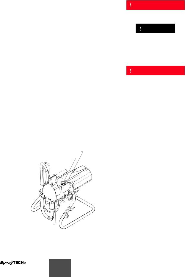
Table des matières |
|
Sécurité |
|||||||||||||||
Introduction ........................................................................... |
12 |
Le présent manuel comprend des renseignements devant être |
|||||||||||||||
Sécurité .................................................................................. |
12 |
lus attentivement avant toute utilisation de l'appareil. Lorsque |
|||||||||||||||
Instructions de mise à la terre............................................. |
14 |
l'un des symboles suivants apparaît, il est recommandé d'être |
|||||||||||||||
Mode d'emploi ....................................................................... |
14 |
particulièrement attentif et de tenir compte des mesures de |
|||||||||||||||
Vidange et amorçage .......................................................... |
14 |
sécurité indiquées. |
|||||||||||||||
.........................Mode d'emploi du pistolet de pulvérisation |
15 |
|
|
|
AVERTISSEMENT |
|
|
|
|
||||||||
Pulvérisation.......................................................................... |
16 |
|
|
|
|
|
|||||||||||
Technique de pulvérisation.................................................. |
16 |
|
|
|
|
|
|
|
|
|
|
||||||
.............................................................................Utilisation |
16 |
Ce symbole indique un danger potentiel pouvant causer des |
|||||||||||||||
Nettoyage............................................................................... |
16 |
blessures graves ou même mortelles. Des renseignements |
|||||||||||||||
Purge de l'appareil............................................................... |
17 |
importants sur la sécurité sont également indiqués. |
|||||||||||||||
Entretien................................................................................. |
17 |
|
|
|
|
|
|
|
|
|
|
||||||
|
|
|
|
ATTENTION |
|
|
|
|
|
||||||||
Entretien quotidien............................................................... |
17 |
|
|
|
|
|
|
|
|
|
|||||||
Entretien du compartiment à liquide.................................... |
17 |
|
|
|
|
|
|
|
|||||||||
..................................Nettoyage de la tête de pulvérisation |
19 |
|
|
|
|
|
|
|
|
|
|
||||||
Ce symbole indique un danger potentiel pouvant causer des |
|||||||||||||||||
Nettoyage du filtre |
19 |
||||||||||||||||
blessures corporelles ou des dommages à l'équipement. Des |
|||||||||||||||||
Remplacement du ressort de valve |
19 |
||||||||||||||||
renseignements importants sur la façon de prévenir tout |
|||||||||||||||||
Accessoires |
19 |
||||||||||||||||
dommage à l'équipement ou toute blessure corporelle mineure |
|||||||||||||||||
Choix du filtre approprié pour le pistolet |
|
||||||||||||||||
|
sont également indiqués. |
||||||||||||||||
de pulvérisation |
19 |
||||||||||||||||
|
|
|
|
|
|
|
|
|
|
||||||||
..............................................................En cas de problème |
20 |
|
NOTA : Les remarques donnent des renseignements |
|
|||||||||||||
Garantie limitée ..................................................................... |
21 |
|
importants requérant une attention particulière. |
|
|||||||||||||
English ..................................................................................... |
2 |
|
|
|
|
|
|
|
|
|
|
||||||
|
|
|
|
|
|
|
|
|
|
||||||||
Español .................................................................................. |
22 |
|
|
|
|
|
|
|
|
|
|
||||||
|
|
|
AVERTISSEMENT |
|
|
|
|
||||||||||
Liste des pièces .................................................................... |
32 |
|
|
|
|
|
|
|
|||||||||
Dispositif de principale ........................................................ |
32 |
|
|
|
|
|
|
|
|||||||||
.................................................................Dispositif de pied |
33 |
DANGER: BLESSURES PAR PERFORATION - Le jet de |
|||||||||||||||
Dispositif de succion............................................................ |
33 |
||||||||||||||||
Dispositif de entraînement................................................... |
34 |
|
peinture à haute pression produit par cet |
||||||||||||||
Transducteur........................................................................ |
35 |
|
appareil peut perforer la peau et les tissus |
||||||||||||||
Relais................................................................................... |
35 |
|
sous-jacents et entraîner de sévères blessures |
||||||||||||||
Dispostif de réglage de la pression..................................... |
36 |
|
pouvant nécessiter une amputation. Consultez |
||||||||||||||
Compartiment liquide........................................................... |
37 |
|
immédiatement un médecin. |
||||||||||||||
Pistolet................................................................................. |
38 |
NE PAS TRAITER UNE BLESSURE PAR PERFORATION |
|||||||||||||||
Valve amorçage/pulvérisation.............................................. |
38 |
COMME UNE SIMPLE COUPURE! Une perforation peut |
|||||||||||||||
Filtre (facultatif).................................................................... |
39 |
entraîner des risques d'amputation. Consultez |
|||||||||||||||
Dispostif de réglage de la pression |
|
immédiatement un médecin. |
|||||||||||||||
connectant le diagramme ................................................ |
40 |
Pression de service maximale du fluide dans l’appareil : |
|||||||||||||||
Introduction |
|
3000 lb/po2 / 207BAR. |
|||||||||||||||
|
MESURES PRÉVENTIVES: |
||||||||||||||||
Cette pompe à piston de haute performance est un appareil |
|
||||||||||||||||
électrique de précision qui peut être utilisé pour la pulvérisation |
|
• NE JAMAIS diriger le pistolet vers une quelconque partie |
|||||||||||||||
d'un grand nombre de produits. Lisez attentivement ce manuel |
|
du corps. |
|||||||||||||||
et suivez scrupuleusement les consignes qui y sont données |
|
|
• NE JAMAIS mettre une quelconque partie du corps en |
||||||||||||||
quant au mode de fonctionnement, à l'entretien et l'utilisation |
|
|
contact avec le jet de liquide. NE JAMAIS se mettre au |
||||||||||||||
sécuritaire de l'appareil. |
|
|
contact d'un jet de liquide provenant d'une fuite du flexible |
||||||||||||||
|
Commutateur marche/arrêt (ON/OFF) |
|
|
d'alimentation en liquide. |
|||||||||||||
|
|
|
• NE JAMAIS placer votre main devant le pistolet. Des |
||||||||||||||
|
|
|
|
|
|
|
|
||||||||||
|
Bouton de réglage de la pression |
|
|
gants ne vous protégeront pas contre les risques de |
|||||||||||||
|
|
|
|
|
|
|
|
blessures par perforation. |
|||||||||
|
|
|
|
|
|
|
|
• TOUJOURS verrouiller la gâchette du pistolet, fermer la |
|||||||||
|
Flexible |
|
|
|
|
|
pompe à liquide et décompresser l'appareil lorsque vous |
||||||||||
|
|
|
|
|
travaillez sur celui-ci, nettoyez le protecteur de tête, |
||||||||||||
|
de retour |
|
|
||||||||||||||
|
|
|
remplacez la tête de pulvérisation ou vous éloignez de |
||||||||||||||
|
|
|
|
|
|
|
|
||||||||||
|
Ensemble |
|
|
|
|
|
|
l'appareil. Couper le moteur ne décompresse pas l'appareil. |
|||||||||
|
|
|
|
|
|
|
Vous devez, pour le décompresser, placer le bouton |
||||||||||
|
de succion |
|
|
||||||||||||||
|
|
|
AMORÇAGE/PULVÉRISATION en position AMORÇAGE. |
||||||||||||||
|
|
|
|
|
|
|
|
||||||||||
|
|
|
|
|
|
|
|
Reportez-vous, pour cela, à la PROCÉDURE DE |
|||||||||
|
|
|
|
|
|
|
|
DÉCOMPRESSION décrite dans de ce manuel. |
|||||||||
|
|
|
|
|
|
|
|
• TOUJOURS s'assurer que le protecteur de tête est en |
|||||||||
|
|
|
|
|
|
|
|
place lorsque vous pulvérisez. Le protecteur de tête offre |
|||||||||
|
|
|
|
|
|
|
|
une certaine protection contre les blessures par perforation |
|||||||||
|
|
|
|
|
|
|
|
mais sa principale fonction est d'ordre préventif. |
|||||||||
|
|
|
|
|
|
|
|
• TOUJOURS ôter la tête de pulvérisation avant de purger |
|||||||||
|
|
|
|
|
|
|
|
ou nettoyer l'appareil. |
|||||||||
|
|
|
|
|
|
|
|
• Le flexible d'alimentation en peinture peut fuir à la suite |
|||||||||
|
|
|
Bouton |
|
|
d'une usure, de chocs ou de mauvais traitements. Une |
|||||||||||
|
|
|
|
|
fuite peut entraîner une perforation de la peau. Inspecter |
||||||||||||
AMORÇAGE/PULVÉRISATION |
|
|
|||||||||||||||
|
|
le flexible avant chaque utilisation. |
|||||||||||||||
|
|
|
|
|
|
|
|
||||||||||
|
|
|
|
|
|
|
|
|
|
|
|
|
|
|
|
|
|
Français 12
 Loading...