


SERVICE MANUAL
VC4G & VC6G SERIES FULL SIZE
CONVECTION OVENS
VC4GS ML-126610
VC4GD ML-126611
VC4GC ML-136494
VC6GS ML-126612
VC6GD ML-126613
VC6GC ML-136495
- NOTICE -
This Manual is prepared for the use of trained Vulcan Service Technicians and should not be used by those not properly qualified.
This manual is not intended to be all encompassing. If you have not attended a Vulcan Service School for this product, you should read, in its entirety, the repair procedure you wish to perform to determine if you have the necessary tools, instruments and skills required to perform the procedure. Procedures for which you do not have the necessary tools, instruments and skills should be performed by a trained Vulcan Service Technician.
The reproduction, transfer, sale or other use of this Manual, without the express written consent of Vulcan, is prohibited.
This manual has been provided to you by ITW Food Equipment Group LLC ("ITW FEG") without charge and remains the property of ITW FEG, and by accepting this manual you agree that you will return it to ITW FEG promptly upon its request for such return at any time in the future.
A product of Vulcan-Hart |
3600 North Point Blvd Baltimore, MD 21222 |
|
F24682 Rev. C (0315) |

VC4G & VC6G SERIES FULL SIZE CONVECTION OVENS
TABLE OF CONTENTS
SERVICE UPDATES . . . . . . . . . . . . . . . . . . . . . . . . . . . . . . . . . . . . . . . . . . . . . . . . . . . . . . . . . . . . . . . . . . . . . . . . . . . . . . . . . . . . . . . 4 SERVICE UPDATES - VC4G / VC6G . . . . . . . . . . . . . . . . . . . . . . . . . . . . . . . . . . . . . . . . . . . . . . . . . . . . . . . . . . . . . . . . . . . 4
GENERAL . . . . . . . . . . . . . . . . . . . . . . . . . . . . . . . . . . . . . . . . . . . . . . . . . . . . . . . . . . . . . . . . . . . . . . . . . . . . . . . . . . . . . . . . . . . . . . . . . . 5 INTRODUCTION . . . . . . . . . . . . . . . . . . . . . . . . . . . . . . . . . . . . . . . . . . . . . . . . . . . . . . . . . . . . . . . . . . . . . . . . . . . . . . . . . . . . . . . 5 INSTALLATION . . . . . . . . . . . . . . . . . . . . . . . . . . . . . . . . . . . . . . . . . . . . . . . . . . . . . . . . . . . . . . . . . . . . . . . . . . . . . . . . . . . . . . . . 5 OPERATION . . . . . . . . . . . . . . . . . . . . . . . . . . . . . . . . . . . . . . . . . . . . . . . . . . . . . . . . . . . . . . . . . . . . . . . . . . . . . . . . . . . . . . . . . . . 5 CLEANING . . . . . . . . . . . . . . . . . . . . . . . . . . . . . . . . . . . . . . . . . . . . . . . . . . . . . . . . . . . . . . . . . . . . . . . . . . . . . . . . . . . . . . . . . . . . . 5 LUBRICATION . . . . . . . . . . . . . . . . . . . . . . . . . . . . . . . . . . . . . . . . . . . . . . . . . . . . . . . . . . . . . . . . . . . . . . . . . . . . . . . . . . . . . . . . . 5 SPECIFICATIONS . . . . . . . . . . . . . . . . . . . . . . . . . . . . . . . . . . . . . . . . . . . . . . . . . . . . . . . . . . . . . . . . . . . . . . . . . . . . . . . . . . . . . . 5 TOOLS . . . . . . . . . . . . . . . . . . . . . . . . . . . . . . . . . . . . . . . . . . . . . . . . . . . . . . . . . . . . . . . . . . . . . . . . . . . . . . . . . . . . . . . . . . . . . . . . . 6
REMOVAL AND REPLACEMENT OF PARTS . . . . . . . . . . . . . . . . . . . . . . . . . . . . . . . . . . . . . . . . . . . . . . . . . . . . . . . . . . . . . . . 7 COVERS AND PANELS . . . . . . . . . . . . . . . . . . . . . . . . . . . . . . . . . . . . . . . . . . . . . . . . . . . . . . . . . . . . . . . . . . . . . . . . . . . . . . . . 7 TOP FRONT COVER . . . . . . . . . . . . . . . . . . . . . . . . . . . . . . . . . . . . . . . . . . . . . . . . . . . . . . . . . . . . . . . . . . . . . . . . . . . . . . . 7 BOTTOM FRONT COVER . . . . . . . . . . . . . . . . . . . . . . . . . . . . . . . . . . . . . . . . . . . . . . . . . . . . . . . . . . . . . . . . . . . . . . . . . . 7 CONTROL PANEL . . . . . . . . . . . . . . . . . . . . . . . . . . . . . . . . . . . . . . . . . . . . . . . . . . . . . . . . . . . . . . . . . . . . . . . . . . . . . . . . . 7 RIGHT SIDE PANEL . . . . . . . . . . . . . . . . . . . . . . . . . . . . . . . . . . . . . . . . . . . . . . . . . . . . . . . . . . . . . . . . . . . . . . . . . . . . . . . . 7 CONTROL PANEL COMPONENTS . . . . . . . . . . . . . . . . . . . . . . . . . . . . . . . . . . . . . . . . . . . . . . . . . . . . . . . . . . . . . . . . . . . . . 8 COMPONENT PANEL COMPONENTS . . . . . . . . . . . . . . . . . . . . . . . . . . . . . . . . . . . . . . . . . . . . . . . . . . . . . . . . . . . . . . . . . 9 TEMPERATURE PROBE (VC4GD/6GD) . . . . . . . . . . . . . . . . . . . . . . . . . . . . . . . . . . . . . . . . . . . . . . . . . . . . . . . . . . . . . . . 10 GAS BURNER . . . . . . . . . . . . . . . . . . . . . . . . . . . . . . . . . . . . . . . . . . . . . . . . . . . . . . . . . . . . . . . . . . . . . . . . . . . . . . . . . . . . . . . . 11 GAS ORIFICE . . . . . . . . . . . . . . . . . . . . . . . . . . . . . . . . . . . . . . . . . . . . . . . . . . . . . . . . . . . . . . . . . . . . . . . . . . . . . . . . . . . . . . . . . 12 GAS SOLENOID VALVE . . . . . . . . . . . . . . . . . . . . . . . . . . . . . . . . . . . . . . . . . . . . . . . . . . . . . . . . . . . . . . . . . . . . . . . . . . . . . . 12 IGNITION CONTROL MODULE . . . . . . . . . . . . . . . . . . . . . . . . . . . . . . . . . . . . . . . . . . . . . . . . . . . . . . . . . . . . . . . . . . . . . . . 14 SPARK IGNITER AND FLAME SENSE . . . . . . . . . . . . . . . . . . . . . . . . . . . . . . . . . . . . . . . . . . . . . . . . . . . . . . . . . . . . . . . . 15 BLOWER AND MOTOR . . . . . . . . . . . . . . . . . . . . . . . . . . . . . . . . . . . . . . . . . . . . . . . . . . . . . . . . . . . . . . . . . . . . . . . . . . . . . . . 15 OVEN DOORS (SIMULTANEOUS DOORS) . . . . . . . . . . . . . . . . . . . . . . . . . . . . . . . . . . . . . . . . . . . . . . . . . . . . . . . . . . . 17 ASSEMBLY REMOVAL . . . . . . . . . . . . . . . . . . . . . . . . . . . . . . . . . . . . . . . . . . . . . . . . . . . . . . . . . . . . . . . . . . . . . . . . . . . 17 DISASSEMBLY . . . . . . . . . . . . . . . . . . . . . . . . . . . . . . . . . . . . . . . . . . . . . . . . . . . . . . . . . . . . . . . . . . . . . . . . . . . . . . . . . . . 18 OVEN DOORS AND BEARINGS (INDEPENDENT DOORS) . . . . . . . . . . . . . . . . . . . . . . . . . . . . . . . . . . . . . . . . . . . . 18 DOOR CATCH BALL ASSEMBLY (INDEPENDENT DOORS) . . . . . . . . . . . . . . . . . . . . . . . . . . . . . . . . . . . . . . . . . . . 19 ROLLER LATCH ASSEMBLY (INDEPENDENT DOORS) . . . . . . . . . . . . . . . . . . . . . . . . . . . . . . . . . . . . . . . . . . . . . . . 19 DOOR WINDOW . . . . . . . . . . . . . . . . . . . . . . . . . . . . . . . . . . . . . . . . . . . . . . . . . . . . . . . . . . . . . . . . . . . . . . . . . . . . . . . . . . . . . . 19 DOOR SWITCH . . . . . . . . . . . . . . . . . . . . . . . . . . . . . . . . . . . . . . . . . . . . . . . . . . . . . . . . . . . . . . . . . . . . . . . . . . . . . . . . . . . . . . . 20 MECHANICAL KX THERMOSTAT (VC4GS/6GS) . . . . . . . . . . . . . . . . . . . . . . . . . . . . . . . . . . . . . . . . . . . . . . . . . . . . . . 21 HIGH LIMIT THERMOSTAT . . . . . . . . . . . . . . . . . . . . . . . . . . . . . . . . . . . . . . . . . . . . . . . . . . . . . . . . . . . . . . . . . . . . . . . . . . . 21 INTERIOR LIGHTS . . . . . . . . . . . . . . . . . . . . . . . . . . . . . . . . . . . . . . . . . . . . . . . . . . . . . . . . . . . . . . . . . . . . . . . . . . . . . . . . . . . . 22 COOLING FAN . . . . . . . . . . . . . . . . . . . . . . . . . . . . . . . . . . . . . . . . . . . . . . . . . . . . . . . . . . . . . . . . . . . . . . . . . . . . . . . . . . . . . . . . 22
SERVICE PROCEDURES AND ADJUSTMENTS . . . . . . . . . . . . . . . . . . . . . . . . . . . . . . . . . . . . . . . . . . . . . . . . . . . . . . . . . . . 24 SOLID STATE TEMPERATURE CONTROL CALIBRATION (VC4GD/6GD) . . . . . . . . . . . . . . . . . . . . . . . . . . . . . 24 MECHANICAL THERMOSTAT CALIBRATION (VC4GS/6GS) . . . . . . . . . . . . . . . . . . . . . . . . . . . . . . . . . . . . . . . . . . 25 SOLID STATE TEMPERATURE CONTROL TEST (VC4GD/6GD) . . . . . . . . . . . . . . . . . . . . . . . . . . . . . . . . . . . . . . 26 TEMPERATURE PROBE TEST (VC4GD/6GD) . . . . . . . . . . . . . . . . . . . . . . . . . . . . . . . . . . . . . . . . . . . . . . . . . . . . . . . . . 27 GAS PRESSURE ADJUSTMENT (UNITS UP TO FEBRUARY 2015) . . . . . . . . . . . . . . . . . . . . . . . . . . . . . . . . . . . 28 GAS VALVE PRESSURE CHECK (UNITS AFTER FEBRUARY 2015) . . . . . . . . . . . . . . . . . . . . . . . . . . . . . . . . . . 29 VERIFICATION OF SPARK AT IGNITOR . . . . . . . . . . . . . . . . . . . . . . . . . . . . . . . . . . . . . . . . . . . . . . . . . . . . . . . . . . . . . . 30 DOOR SWITCH ADJUSTMENT . . . . . . . . . . . . . . . . . . . . . . . . . . . . . . . . . . . . . . . . . . . . . . . . . . . . . . . . . . . . . . . . . . . . . . . 31 BLOWER ADJUSTMENT . . . . . . . . . . . . . . . . . . . . . . . . . . . . . . . . . . . . . . . . . . . . . . . . . . . . . . . . . . . . . . . . . . . . . . . . . . . . . . 31 DOOR ADJUSTMENT . . . . . . . . . . . . . . . . . . . . . . . . . . . . . . . . . . . . . . . . . . . . . . . . . . . . . . . . . . . . . . . . . . . . . . . . . . . . . . . . . 31 DOOR STRIKE ADJUSTMENT (INDEPENDENT DOORS) . . . . . . . . . . . . . . . . . . . . . . . . . . . . . . . . . . . . . . . . . . . . . 32 DOOR CATCH BALL ADJUSTMENT (INDEPENDENT DOORS) . . . . . . . . . . . . . . . . . . . . . . . . . . . . . . . . . . . . . . . . 33 DOOR CHAIN ADJUSTMENT (SIMULTANEOUS DOORS) . . . . . . . . . . . . . . . . . . . . . . . . . . . . . . . . . . . . . . . . . . . . . 34
INTRODUCTION . . . . . . . . . . . . . . . . . . . . . . . . . . . . . . . . . . . . . . . . . . . . . . . . . . . . . . . . . . . . . . . . . . . . . . . . . . . . . . . . . . 34 PROCEDURE . . . . . . . . . . . . . . . . . . . . . . . . . . . . . . . . . . . . . . . . . . . . . . . . . . . . . . . . . . . . . . . . . . . . . . . . . . . . . . . . . . . . . 34 COMPUTER CONTROL (VC4GC/VC6GC) . . . . . . . . . . . . . . . . . . . . . . . . . . . . . . . . . . . . . . . . . . . . . . . . . . . . . . . . . . . . . 35
F24682 Rev. C (0315) |
|
Page 2 of 74 |
|

VC4G & VC6G SERIES FULL SIZE CONVECTION OVENS
OPERATION . . . . . . . . . . . . . . . . . . . . . . . . . . . . . . . . . . . . . . . . . . . . . . . . . . . . . . . . . . . . . . . . . . . . . . . . . . . . . . . . . . . . . . 35 SETUP MODE . . . . . . . . . . . . . . . . . . . . . . . . . . . . . . . . . . . . . . . . . . . . . . . . . . . . . . . . . . . . . . . . . . . . . . . . . . . . . . . . . . . . 35 PROBE TEST . . . . . . . . . . . . . . . . . . . . . . . . . . . . . . . . . . . . . . . . . . . . . . . . . . . . . . . . . . . . . . . . . . . . . . . . . . . . . . . . . . . . . 35 SOLID STATE RELAY TEST . . . . . . . . . . . . . . . . . . . . . . . . . . . . . . . . . . . . . . . . . . . . . . . . . . . . . . . . . . . . . . . . . . . . . . 35 COMPUTER CONTROL CALIBRATION (VC4GC/VC6GC) . . . . . . . . . . . . . . . . . . . . . . . . . . . . . . . . . . . . . . . . . . . . . 35
ELECTRICAL OPERATION . . . . . . . . . . . . . . . . . . . . . . . . . . . . . . . . . . . . . . . . . . . . . . . . . . . . . . . . . . . . . . . . . . . . . . . . . . . . . . . . 37 COMPONENT FUNCTION . . . . . . . . . . . . . . . . . . . . . . . . . . . . . . . . . . . . . . . . . . . . . . . . . . . . . . . . . . . . . . . . . . . . . . . . . . . . 37 COMPONENT LOCATION . . . . . . . . . . . . . . . . . . . . . . . . . . . . . . . . . . . . . . . . . . . . . . . . . . . . . . . . . . . . . . . . . . . . . . . . . . . . . 38 SEQUENCE OF OPERATION . . . . . . . . . . . . . . . . . . . . . . . . . . . . . . . . . . . . . . . . . . . . . . . . . . . . . . . . . . . . . . . . . . . . . . . . . 43 VC4GS, VC6GS WITH ROAST & HOLD OPTION (MECHANICAL KX THERMOSTAT) . . . . . . . . . . . . . . 43
VC4GD, VC6GD WITH ROAST & HOLD OPTION (SOLID STATE
TEMPERATURE CONTROL) . . . . . . . . . . . . . . . . . . . . . . . . . . . . . . . . . . . . . . . . . . . . . . . . . . . . . . . . . . . . . . . . . . 47 VC4GC, VC6GC (ROAST & HOLD STANDARD ON COMPUTER MODEL) . . . . . . . . . . . . . . . . . . . . . . . . . 53 COOL DOWN CYCLE (COMPUTER CONTROL MODEL) . . . . . . . . . . . . . . . . . . . . . . . . . . . . . . . . . . . . . . . . . . 55
SCHEMATICS . . . . . . . . . . . . . . . . . . . . . . . . . . . . . . . . . . . . . . . . . . . . . . . . . . . . . . . . . . . . . . . . . . . . . . . . . . . . . . . . . . . . . . . . . . . . 56 VC4GS, VC6GS MECHANICAL (KX) CONTROLS . . . . . . . . . . . . . . . . . . . . . . . . . . . . . . . . . . . . . . . . . . . . . . . . . . . . . 56 VC4GS, VC6GS MECHANICAL (KX) CONTROLS, ROAST & HOLD OPTION . . . . . . . . . . . . . . . . . . . . . . . . . . . 57 VC4GD, VC6GD SOLID STATE TEMPERATURE CONTROL . . . . . . . . . . . . . . . . . . . . . . . . . . . . . . . . . . . . . . . . . . 58 VC4GD, VC6GD SOLID STATE TEMPERATURE CONTROL, ROAST & HOLD OPTION . . . . . . . . . . . . . . . . 59 VC4GC, VC6GC COMPUTER CONTROL (ROAST & HOLD STANDARD) . . . . . . . . . . . . . . . . . . . . . . . . . . . . . . 60
WIRING DIAGRAMS . . . . . . . . . . . . . . . . . . . . . . . . . . . . . . . . . . . . . . . . . . . . . . . . . . . . . . . . . . . . . . . . . . . . . . . . . . . . . . . . . . . . . . 61 VC4GS, VC6GS MECHANICAL (KX) CONTROLS . . . . . . . . . . . . . . . . . . . . . . . . . . . . . . . . . . . . . . . . . . . . . . . . . . . . . 61 VC4GS, VC6GS MECHANICAL (KX) CONTROLS, ROAST & HOLD OPTION . . . . . . . . . . . . . . . . . . . . . . . . . . . 63 VC4GD, VC6GD SOLID STATE TEMPERATURE CONTROL . . . . . . . . . . . . . . . . . . . . . . . . . . . . . . . . . . . . . . . . . . 65 VC4GD, VC6GD SOLID STATE TEMPERATURE CONTROL, ROAST & HOLD OPTION . . . . . . . . . . . . . . . . 67 VC4GC, VC6GC COMPUTER CONTROL (ROAST & HOLD STANDARD) . . . . . . . . . . . . . . . . . . . . . . . . . . . . . . 69
TROUBLESHOOTING . . . . . . . . . . . . . . . . . . . . . . . . . . . . . . . . . . . . . . . . . . . . . . . . . . . . . . . . . . . . . . . . . . . . . . . . . . . . . . . . . . . . . 71 ALL MODELS . . . . . . . . . . . . . . . . . . . . . . . . . . . . . . . . . . . . . . . . . . . . . . . . . . . . . . . . . . . . . . . . . . . . . . . . . . . . . . . . . . . . . . . . . 71 COMPUTER CONTROL MODELS ONLY . . . . . . . . . . . . . . . . . . . . . . . . . . . . . . . . . . . . . . . . . . . . . . . . . . . . . . . . . . . . . . 72 ERROR CODES . . . . . . . . . . . . . . . . . . . . . . . . . . . . . . . . . . . . . . . . . . . . . . . . . . . . . . . . . . . . . . . . . . . . . . . . . . . . . . . . . . 73
© VULCAN 2015
Page 3 of 74 |
|
F24682 Rev. C (0315) |
|

VC4G & VC6G SERIES FULL SIZE CONVECTION OVENS - SERVICE UPDATES
SERVICE UPDATES
SERVICE UPDATES - VC4G / VC6G
March 2015
Updated Photos Added to the Following Data
Modules
•GAS BURNER
•GAS ORIFICE
•GAS SOLENOID VALVE
•ROLLER LATCH ASSEMBLY (INDEPENDENT DOORS)
•HIGH LIMIT THERMOSTAT
•GAS PRESSURE ADJUSTMENT (units up to February 2015)
Added New Data Module
•GAS VALVE PRESSURE CHECK (units after February 2015)
VC4GC AND VC6GC Serial Number Breaks
•SPECIFICATIONS
Updated Data Module
•SOLID STATE TEMPERATURE CONTROL CALIBRATION (VC4GD/6GD)
F24682 Rev. C (0315) |
|
Page 4 of 74 |
|
VC4G & VC6G SERIES FULL SIZE CONVECTION OVENS - GENERAL
GENERAL
INTRODUCTION
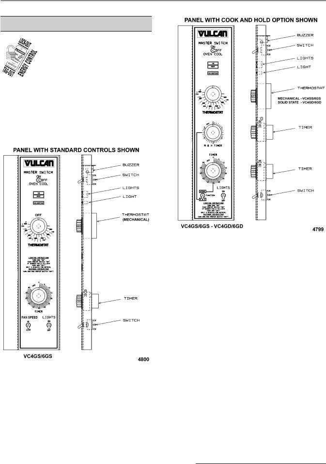
Procedures in this manual will apply to all models unless specified. Pictures and illustrations can be of any model unless the picture or illustration needs to be model specific.
Models
|
|
FEATURES |
|
|
OPTIONS |
|||
|
|
|
|
|
COOK |
|
|
|
MODEL |
CAVITY |
TEMPERTURE |
DOORS |
COOK |
TIMER |
COOK |
BLOWER |
|
OR |
& |
|||||||
|
DEPTH |
CONTROL |
(50/50) |
TIMER |
208/240/60/1 |
|||
|
HOLD |
HOLD |
||||||
|
|
|
|
|
|
|||
|
|
|
|
|
TIMER |
|
|
|
VC4GS |
26.5" |
Mechanical (KX) |
Independent 1 2 |
1-Hour Dial |
5-Hour Dial |
Optional |
Optional |
|
VC6GS |
30.5" |
Mechanical (KX) |
Independent 1 2 |
1-Hour Dial |
5-Hour Dial |
Optional |
Optional |
|
VC4GD |
26.5" |
Solid State |
Independent 1 3 |
1-Hour Dial |
5-Hour Dial |
Optional |
Optional |
|
VC6GD |
30.5" |
Solid State |
Independent 1 3 |
1-Hour Dial |
5-Hour Dial |
Optional |
Optional |
|
VC4GC |
26.5" |
Computer |
Independent 1 3 |
24-Hour |
Built in |
Built in |
Optional |
|
|
|
|
|
Digital |
|
|
|
|
VC6GC |
30.5" |
Computer |
Independent 1 3 |
24-Hour |
Built in |
Built in |
Optional |
|
|
|
|
|
Digital |
|
|
|
|
1 Simultaneous doors are optional (with or w/o window).
2 Stainless steel doors w/o window (standard).
3 Stainless steel doors with window (standard).
INSTALLATION
Refer to the Instructions Manual for detailed installation instructions on single or stacked ovens.
OPERATION
Refer to the Instructions Manual for specific operating instructions.
CLEANING
Refer to the Instructions Manual for specific cleaning instructions.
LUBRICATION
•Cavity blower motor has sealed bearings and requires no additional lubrication.
•Huskey™ TF-1000 grease or equivalent high temperature Teflon grease.
SPECIFICATIONS
Electrical
Voltage - 120/60/1
Amps - 8.0 Amps
Input BTU Rating
Natural Gas - 44,000 BTU input at 3.5 in. W.C.
Page 5 of 74 |
|
F24682 Rev. C (0315) |
|

VC4G & VC6G SERIES FULL SIZE CONVECTION OVENS - GENERAL
Units after Serial Number Break (VC4GD 481835388, VC6GD 481835406, VC4GD 541077665) Natural Gas - 50,000 BTU input at 5.0 in. W.C.
Propane Gas - 44,000 BTU input at 10.0 in. W.C.
Units after Serial Number Break (VC4GD 481835394 & 541077965, VC6GD 481835429) Propane Gas - 50,000 BTU input at 10.0 in. W.C.
Gas Line Pressures
Natural - Recommend (in. W.C.) 7.0, Min 5.0
Natural - Recommend (in W.C.) 8.0, Min 6.0 for Units after Serial Number Break (VC4GD 481835388, VC6GD 481835406, VC4GD 541077665)
Propane - Recommend (in. W.C.) 11.0, Min 11.0 (All Propane Units)
Maximum 14.0 in. W.C. (Nat. or Prop.)
TOOLS
Standard
•Standard set of hand tools
•VOM with ability to measure micro amp current
VOM with minimum of NFPA-70E CAT III 600V, UL/CSA/TUV listed. Sensitivity of at least 20,000 ohms per volt. Meter leads must also be rated at CAT III 600V.
•Gear Puller to remove blower
Special
•Temperature tester (thermocouple type)
•Manometer
F24682 Rev. C (0315) |
|
Page 6 of 74 |
|

VC4G & VC6G SERIES FULL SIZE CONVECTION OVENS - REMOVAL AND REPLACEMENT OF PARTS
REMOVAL AND REPLACEMENT OF PARTS
COVERS AND PANELS
 Disconnect the
electrical power to the machine and follow lockout / tagout procedures.
 SHUT OFF THE GAS BEFORE SERVICING THE UNIT.
Top Front Cover
1.The top front cover is secured with four (4) screws, two on each side of cover. Remove these screws then remove the cover from the oven.
Fig. 1
2. Reverse the procedure to install.
Bottom Front Cover
1.The bottom front cover is secured with four (4) screws, two on each side of cover. Remove these screws then remove the cover from the oven.
Fig. 2
2. Reverse the procedure to install.
Control Panel
1.Remove three (3) screws on the right side which secure the control panel then pull the panel away from the oven.
Fig. 3
NOTE: If the oven has a mechanical (KX type) thermostat, it must be removed from the control panel first, before removing the control panel.
2.Disconnect the temperature probe leads from the solid state temperature control.
3.Unplug the wire harness connector to the control panel components.
4.Reverse the procedure to install.
Right Side Panel
1.Remove the screws which secure the right side of the top front cover, bottom front cover and control panel.
2.Remove the remaining six screws securing the right side panel.
Fig. 4
3.Pull the right side panel out at the bottom then down to remove.
4.Reverse the procedure to install.
Page 7 of 74 |
|
F24682 Rev. C (0315) |
|
VC4G & VC6G SERIES FULL SIZE CONVECTION OVENS - REMOVAL AND REPLACEMENT OF PARTS
CONTROL PANEL COMPONENTS
 Disconnect the
electrical power to the machine and follow lockout / tagout procedures.
Removable Components Procedure
1.Remove the Control Panel.
2.Remove the component being replaced.
3.Reverse the procedure to install the replacement component, then check oven for proper operation.
Fig. 6
Fig. 5
F24682 Rev. C (0315) |
|
Page 8 of 74 |
|

VC4G & VC6G SERIES FULL SIZE CONVECTION OVENS - REMOVAL AND REPLACEMENT OF PARTS
Fig. 7 |
Fig. 8 |
|
COMPONENT PANEL
COMPONENTS
 Disconnect the
electrical power to the machine and follow lockout / tagout procedures.
Removable Components Procedure
1.Remove the Right Side Panel.
NOTE: If right side panel is not accessible, this component can be serviced by removing the Control Panel.
2.Disconnect the wire leads to the component being replaced.
3.Remove the component.
4.Reverse the procedure to install the replacement component and check oven for proper operation.
Page 9 of 74 |
|
F24682 Rev. C (0315) |
|

VC4G & VC6G SERIES FULL SIZE CONVECTION OVENS - REMOVAL AND REPLACEMENT OF PARTS
Fig. 10
Fig. 9
TEMPERATURE PROBE (VC4GD/ 6GD)
 Disconnect the
electrical power to the machine and follow lockout / tagout procedures.
1. Remove the Right Side Panel.
NOTE: If right side panel is not accessible, this component can be serviced by removing the Control Panel.
2. Disconnect the probe leads from the solid state temperature control.
3. Remove the racks and right rack support.
4. Remove the probe guard.
F24682 Rev. C (0315) |
|
Page 10 of 74 |
|
VC4G & VC6G SERIES FULL SIZE CONVECTION OVENS - REMOVAL AND REPLACEMENT OF PARTS
Fig. 11
5.Remove probe by pushing it through the oven wall and into the control panel area.
Fig. 12
NOTE: The hole in the oven cavity wall does not line up straight with the oven cavity outer shell, therefore the probe must be removed at an angle.
6.Reverse the procedure to install the replacement probe.
7.Adjust the temperature control as outlined under SOLID STATE TEMPERATURE CONTROL CALIBRATION (VC4GD/6GD).
GAS BURNER
 Disconnect the
electrical power to the machine and follow lockout / tagout procedures.
 SHUT OFF THE GAS BEFORE SERVICING THE UNIT.
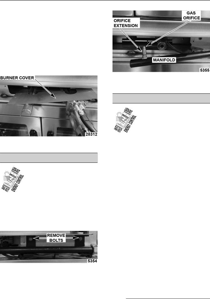
1.Remove the BOTTOM FRONT COVER.
2.Disconnect the ignition cable and the flame sense lead wire.
Fig. 13
3.Remove the bolts securing the gas manifold to the oven and place the manifold to the side.
Fig. 14
4.Remove the screws securing the burner cover then lift out.
Fig. 15
5.Grasp the burner and lift out.
Fig. 16
Page 11 of 74 |
|
F24682 Rev. C (0315) |
|
VC4G & VC6G SERIES FULL SIZE CONVECTION OVENS - REMOVAL AND REPLACEMENT OF PARTS
6.Reverse procedure to install the replacement burner.
NOTE: Ensure that burner positioning bracket (U shaped end) is inserted into slot at the rear of the burner chamber.
NOTE: When installing current production burner covers:
•Lay cover flat over burner with openings aligned behind ignitor.
•Push burner into unit and flip cover 90° up and align mounting holes.
CURRENT PRODUCTION UNIT SHOWN
7.Check for proper operation.
GAS ORIFICE
 Disconnect the
electrical power to the machine and follow lockout / tagout procedures.
 SHUT OFF THE GAS BEFORE SERVICING THE UNIT.
1.Remove the Bottom Front Cover.
2.Remove the bolts securing the gas manifold to the oven and place the manifold to the side.
Fig. 19
4.Reverse procedure to install and check for proper operation.
GAS SOLENOID VALVE
 Disconnect the
electrical power to the machine and follow lockout / tagout procedures.
 SHUT OFF THE GAS BEFORE SERVICING THE UNIT.
1.Remove the CONTROL PANEL and the RIGHT SIDE PANEL.
NOTE: if right side panel is not accessible, this component can be serviced by removing the CONTROL PANEL.
2.Disconnect the lead wires.
3.Disconnect the compression fittings to the valve.
Fig. 18
3.Remove the gas orifice from the spud on the manifold and replace with the correct orifice for the given altitude.
F24682 Rev. C (0315) |
|
Page 12 of 74 |
|

VC4G & VC6G SERIES FULL SIZE CONVECTION OVENS - REMOVAL AND REPLACEMENT OF PARTS
FIRST GENERATION UNIT SHOWN (Before April
2005)
CURRENT PRODUCTION SHOWN (After February
2015)
4.Loosen the bolts securing the valve and bracket assembly then remove the screws securing the valve to the bracket.
SECOND GENERATION UNIT SHOWN (After April
2005 thru February 2015)
FIRST GENERATION UNIT SHOWN (Before April
2005)
Page 13 of 74 |
|
F24682 Rev. C (0315) |
|
VC4G & VC6G SERIES FULL SIZE CONVECTION OVENS - REMOVAL AND REPLACEMENT OF PARTS
SECOND GENERATION UNIT SHOWN (After April
2005 thru February 2015)
CURRENT PRODUCTION SHOWN (After February
2015)
5.Reverse the procedure to install the replacement gas valve.
NOTE: Clean the pipe threads and apply pipe joint compound to threads. Any pipe joint compound used, must be resistant to the action of propane gases.
 All gas joints disturbed during
servicing must be checked for leaks. Check with a soap and water solution (bubbles). Do not use an open flame.
6.Verify gas pressure as outlined under GAS PRESSURE ADJUSTMENT (for units before February 2015) and GAS VALVE PRESSURE CHECK (for units after February 2015) and check for proper operation.
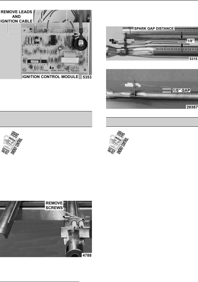
IGNITION CONTROL MODULE
 Disconnect the
electrical power to the machine and follow lockout / tagout procedures.
 SHUT OFF THE GAS BEFORE SERVICING THE UNIT.
1.Remove the Right Side Panel.
NOTE: If right side panel is not accessible, this component can be serviced by removing the Control Panel.
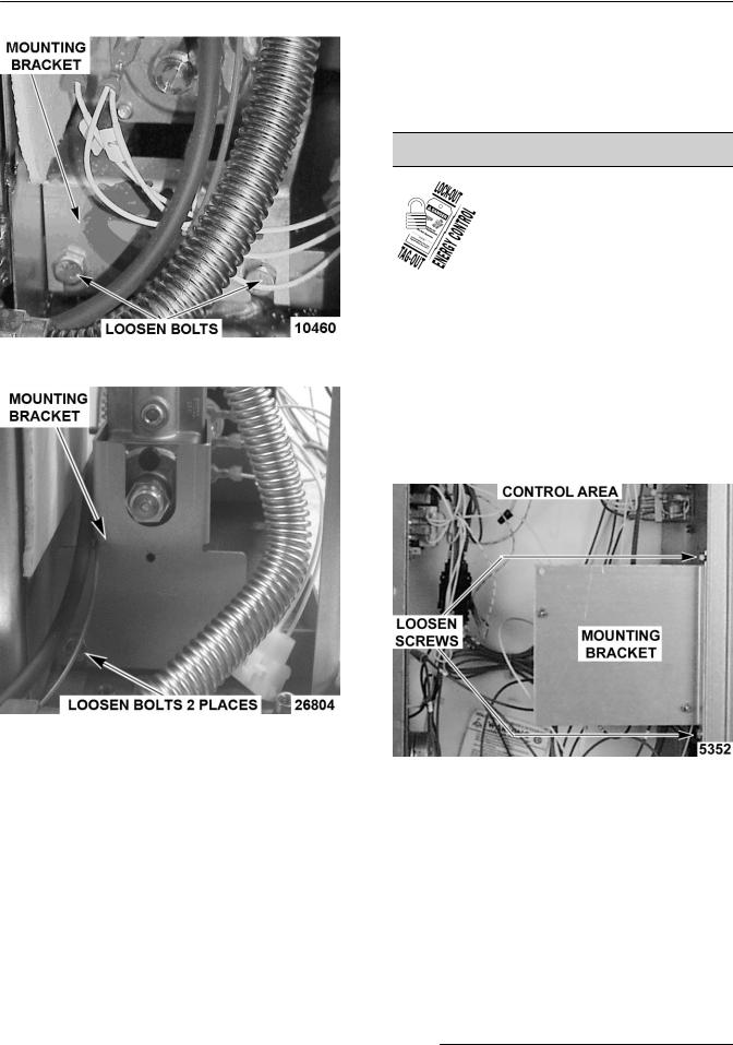
2.Loosen the screws securing the mounting bracket to the component panel and remove the bracket.
Fig. 26
3.Disconnect the lead wires and igniter cable from the ignition module board.
F24682 Rev. C (0315) |
|
Page 14 of 74 |
|
VC4G & VC6G SERIES FULL SIZE CONVECTION OVENS - REMOVAL AND REPLACEMENT OF PARTS
Fig. 27
4.Remove the ignition module board from the mounting bracket.
5.Reverse the procedure to install the replacement ignition module board.
SPARK IGNITER AND FLAME
SENSE
 Disconnect the
electrical power to the machine and follow lockout / tagout procedures.
 SHUT OFF THE GAS BEFORE SERVICING THE UNIT.
1.Remove the gas burner as outlined under GAS BURNER.
2.Remove the screws securing the ignitor and flame sense to burner then remove the assembly.
NOTE: Check to ensure the spark gap distance is approximately 1/8". If the gap appears to be excessive or poor sparking is occurring then adjust.
PREVOUS PRODUCTION SHOWN
CURRENT PRODUCTION SHOWN
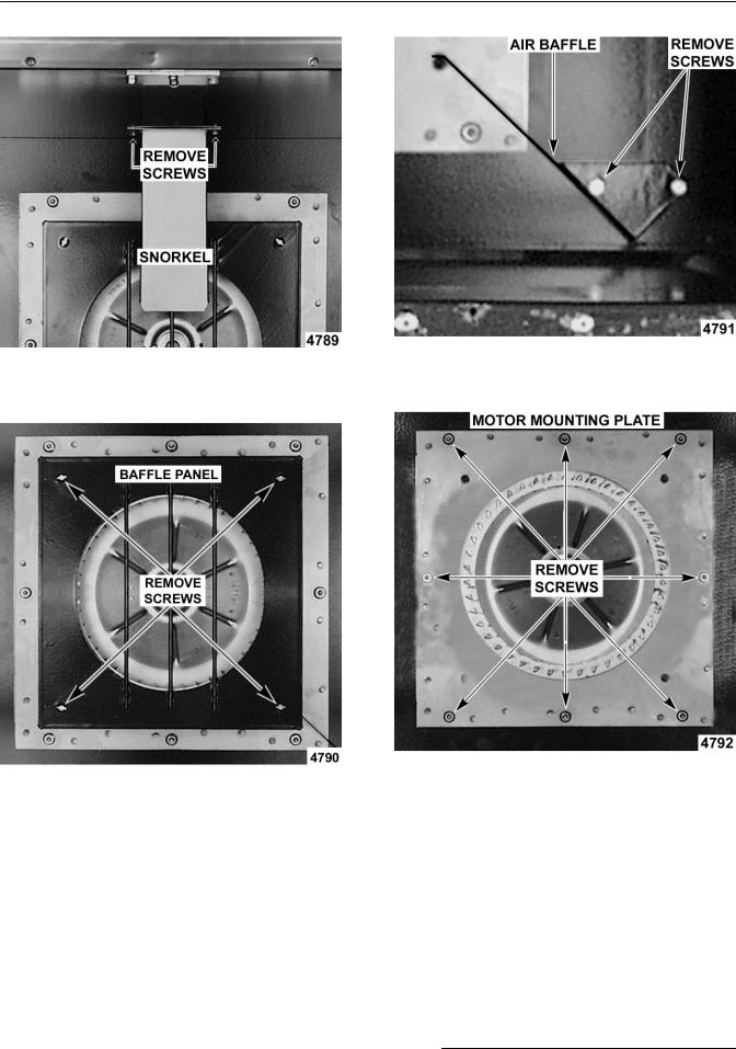
BLOWER AND MOTOR
 Disconnect the
electrical power to the machine and follow lockout / tagout procedures.
 SHUT OFF THE GAS BEFORE SERVICING THE UNIT.
1.Take out the racks and rack supports.
2.Remove screws securing the “snorkel” and remove the snorkel.
Fig. 28
3.Reverse the procedure to install the assembly and check for proper operation.
Page 15 of 74 |
|
F24682 Rev. C (0315) |
|
VC4G & VC6G SERIES FULL SIZE CONVECTION OVENS - REMOVAL AND REPLACEMENT OF PARTS
Fig. 31
3.Remove screws securing baffle panel and remove the panel.
Fig. 32
4.If replacing:
A.Blower Only - Loosen set screws on blower hub and using a bearing puller, remove blower from motor shaft.
1)Reverse procedure to install and adjust blower position as outlined under BLOWER ADJUSTMENT.
B.Motor - perform step 4A and continue procedure.
5.Remove the screws securing the air baffle to the rear wall at the lower right hand corner.
Fig. 33
6.Remove the nuts that secure the motor mounting plate to the rear wall.
Fig. 34
7.Place a piece of cardboard on the bottom of the oven cavity to protect its surface from any damage during motor assembly removal.
8.Pull the motor assembly into the oven cavity and place it on the cardboard.
9.Remove the junction box cover from the motor, disconnect lead wires and remove the conduit.
10.Remove motor mounting bolts and flat washers then lift the motor from the mounting plate.
11.Position the replacement motor on the motor mounting plate and install mounting bolts and washers. Hand tighten mounting bolts only.
F24682 Rev. C (0315) |
|
Page 16 of 74 |
|
VC4G & VC6G SERIES FULL SIZE CONVECTION OVENS - REMOVAL AND REPLACEMENT OF PARTS
12.Reconnect lead wires at the motor, replace conduit and junction box cover.
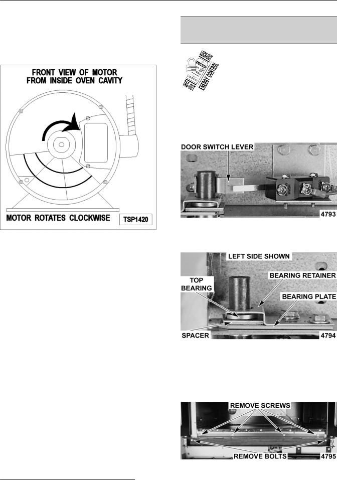
NOTE: Check data plate on motor for wiring schematic. The motor must rotate clockwise when viewed from the shaft end.
Fig. 35
13.Slide blower onto motor shaft until hub is flush with end of shaft then tighten set screws.
14.Adjust motor position until blower is parallel to motor mounting plate as outlined under BLOWER ADJUSTMENT.
15.Position motor mounting plate on the rear wall and secure with nuts and washers.
16.Replace the baffle panel and “snorkel”.
17.Replace the air baffle on the rear wall at the lower right hand corner.
18.Remove cardboard from the bottom of the oven cavity.
19.Install rack guides and racks.
20.Check oven for proper operation.
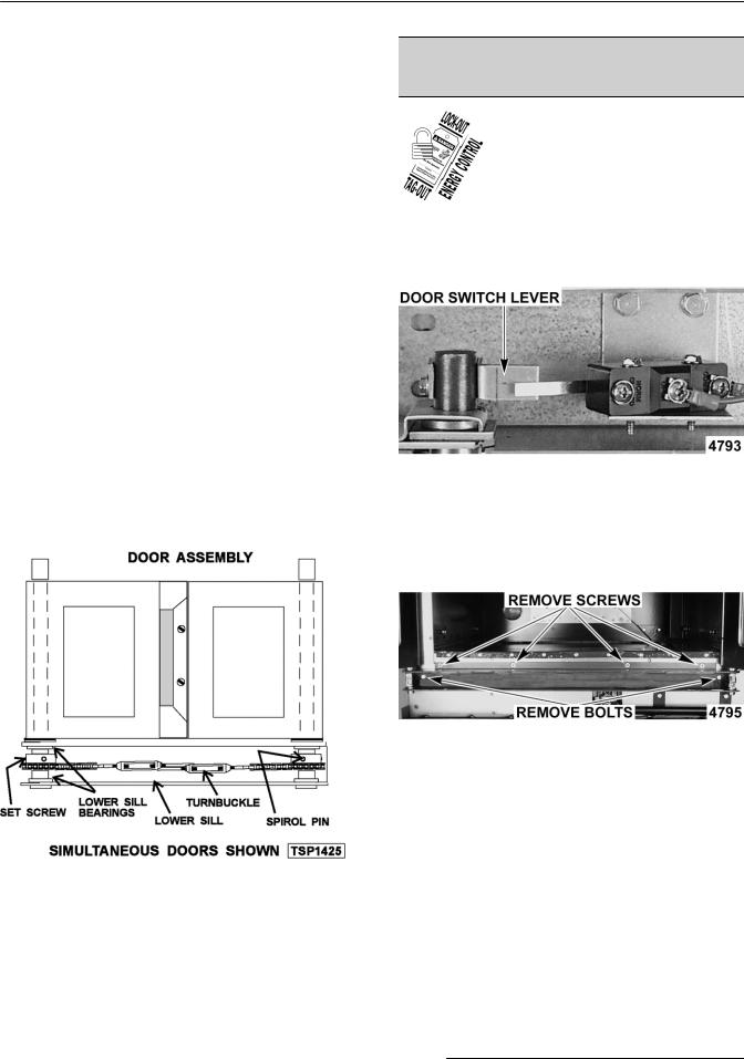
OVEN DOORS (SIMULTANEOUS
DOORS)
 Disconnect the
electrical power to the machine and follow lockout / tagout procedures.
Assembly Removal
1.Remove the Top Front Cover and Bottom Front Cover.
2.Remove the door switch lever.
Fig. 36
3.Remove the top bearing retainers and top bearings.
Fig. 37
4.Remove the lower door seal strip to expose the mounting screws of the door assembly.
A.Remove the two (2) lower sill bolts by the lower door shaft and the four (4) countersunk screws from the lower sill.
Fig. 38
Page 17 of 74 |
|
F24682 Rev. C (0315) |
|
VC4G & VC6G SERIES FULL SIZE CONVECTION OVENS - REMOVAL AND REPLACEMENT OF PARTS
NOTE: The door assembly is heavy and will drop down once the last screw is removed. If removing door assembly with-out assistance, use caution.
5.Lift up on the door assembly and swing the right side out then move the assembly to the left to clear the slots in the upper door sill.
6.Lay the door assembly on a flat cushioned surface for disassembly.
7.Reverse procedure to install door assembly and check for proper adjustment as outlined under DOOR ADJUSTMENT, DOOR CHAIN ADJUSTMENT (SIMULTANEOUS DOORS) and DOOR SWITCH ADJUSTMENT.
Disassembly
1.Remove the door assembly as outlined in "ASSEMBLY REMOVAL".
2.Remove the door chain by loosening one of the turnbuckles.
3.Loosen the set screw on the sprocket of door being replaced.
4.Drive out the Spirol pin from the sprocket of door being replaced.
5.Remove the door from lower sill bearings and sprocket.
Fig. 39
A.Door assembly parts are now accessible for inspection and/or replacement if necessary.
6.Reverse procedure to re-assemble the door assembly parts and check for proper adjustment as outlined under DOOR CHAIN ADJUSTMENT (SIMULTANEOUS DOORS).
OVEN DOORS AND BEARINGS (INDEPENDENT DOORS)
 Disconnect the
electrical power to the machine and follow lockout / tagout procedures.
1.Remove the Top Front Cover and Bottom Front Cover.
2.Remove the door switch lever.
Fig. 40
3.Remove the lower door seal strip to expose the mounting screws of the door assembly.
4.Remove the two (2) lower sill bolts by the lower door shaft and the four (4) counter-sunk screws from the lower sill.
Fig. 41
NOTE: The door assembly is heavy and will drop down once the last screw is removed. If removing door assembly with-out assistance, the ignition cable, flame sense lead and gas manifold should also be removed to avoid damage to these components.
5.Tilt the top of the door slightly forward and lift the door up until the bottom of the door shaft clears the opening in the sill.
6.Lay the door flat to prevent damage.
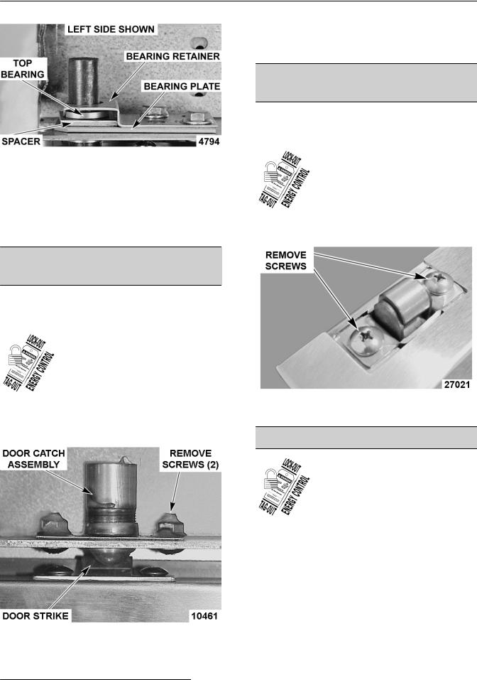
7.The top and bottom bearings are now accessible for inspection and/or replacement if needed.
A.If bearings are OK, proceed to step 8.
B.If replacing the top bearing, remove the top bearing retainer and top bearing.
F24682 Rev. C (0315) |
|
Page 18 of 74 |
|
VC4G & VC6G SERIES FULL SIZE CONVECTION OVENS - REMOVAL AND REPLACEMENT OF PARTS
Fig. 42
C.If replacing the bottom bearing, remove it from the door shaft or the lower sill opening.
8.Reverse procedure to install door assembly and check for proper adjustment as outlined under DOOR ADJUSTMENT and DOOR SWITCH ADJUSTMENT.
4.Adjust the ball catch as outlined under DOOR CATCH BALL ADJUSTMENT (INDEPENDENT DOORS).
ROLLER LATCH ASSEMBLY (INDEPENDENT DOORS)
NOTE: For units with serial number starting with 48 made after 8/12/07 and serial number starting with 54 made after 8/26/07.
 Disconnect the
electrical power to the machine and follow lockout / tagout procedures.
1.Remove the screws that attach roller latch assembly to door.
DOOR CATCH BALL ASSEMBLY (INDEPENDENT DOORS)
NOTE: For units with serial number starting with 48 made before 8/13/07 and serial number starting with 54 made before 8/27/07.
 Disconnect the
electrical power to the machine and follow lockout / tagout procedures.
1.Remove the FRONT COVER.
2.Remove the screws that secure the door catch assembly.
Fig. 44
2.Reverse procedure to install.
DOOR WINDOW
 Disconnect the
electrical power to the machine and follow lockout / tagout procedures.
1.Remove the screws at the top and bottom of door.
Fig. 43
3.Reverse procedure to install.
Page 19 of 74 |
|
F24682 Rev. C (0315) |
|

VC4G & VC6G SERIES FULL SIZE CONVECTION OVENS - REMOVAL AND REPLACEMENT OF PARTS
Fig. 45
2.Independent doors:
A.Remove the door handle then remove the outer door panel.
B.Lift out the inner door panel and window assembly.
NOTE: Left door only - remove door seal from the inside edge of the door.
3.Simultaneous doors:
A.If replacing window on the left door, remove the handle from the front of the door then remove door seal from the inside edge of the door.
1)Lift out the inner door panel and window assembly.
2)If replacing window on the right door, remove the screws along the inside edge (if applicable) of the door then remove the inner door panel and window assembly.
4.Remove the screws securing the window “tabs” to the door bracket and lift the window assembly out from the door frame.
Fig. 46
5.Reverse procedure to install the replacement window.
DOOR SWITCH
 Disconnect the
electrical power to the machine and follow lockout / tagout procedures.
1.Remove the Top Front Cover.
2.Disconnect the lead wires to the door switch.
3.Remove the switch.
F24682 Rev. C (0315) |
|
Page 20 of 74 |
|
VC4G & VC6G SERIES FULL SIZE CONVECTION OVENS - REMOVAL AND REPLACEMENT OF PARTS
Fig. 47
4.Reverse procedure to install the replacement switch and check for proper adjustment as outlined under DOOR SWITCH ADJUSTMENT.
MECHANICAL KX THERMOSTAT (VC4GS/6GS)
 Disconnect the
electrical power to the machine and follow lockout / tagout procedures.
1.Remove the racks and right rack support.
2.Remove the thermostat knob and mounting screws from the control panel and then remove the control panel.
3.Remove the probe guard from the oven cavity wall.
NOTE: When installing, the probe should not extend beyond the probe guard.
4.Remove the thermostat bulb from the oven cavity by pushing it through the oven wall and into the control panel area.
NOTE: The hole in the oven cavity wall does not line up straight with the oven cavity outer shell, therefore the probe must be removed at an angle.
5.Reverse the procedure to install.
6.Adjust the thermostat as outlined under MECHANICAL THERMOSTAT CALIBRATION (VC4GS/6GS).
HIGH LIMIT THERMOSTAT
 Disconnect the
electrical power to the machine and follow lockout / tagout procedures.
1.Take out racks from the oven.
2.Remove the high limit thermostat cover/mounting plate from inside the oven cavity at the top.
Fig. 48
3.Disconnect lead wires from high limit thermostat then remove high limit thermostat from cover/ mounting plate.
Fig. 49
NOTE: Remove the old RTV from the cover and mating surfaces inside the oven cavity and apply new RTV before installing.
4.Reverse procedure to install.
Page 21 of 74 |
|
F24682 Rev. C (0315) |
|

VC4G & VC6G SERIES FULL SIZE CONVECTION OVENS - REMOVAL AND REPLACEMENT OF PARTS
INTERIOR LIGHTS
 Disconnect the
electrical power to the machine and follow lockout / tagout procedures.
Lamp
1.Remove the racks.
2.Unscrew the glass lens for the light being replaced then unscrew the bulb.
Fig. 50
3.Replace bulb then reverse the procedure to install.
 Disconnect the
electrical power to the machine and follow lockout / tagout procedures.
Lamp Assembly
1.Remove the lens and bulb.
2.Remove the springs from the retaining tabs (2 places) on the socket.
3.Depress the retaining tabs and pull the socket out from the oven, far enough to disconnect the lead wires.
4.Remove the socket from the oven.
5.Attach the lead wires to the replacement socket.
6.Insert the socket into the hole in the oven and push until the socket is held in place by the retaining tabs.
7.Install the light bulb and lens.
8.Check for proper operation.
COOLING FAN
 Disconnect the
electrical power to the machine and follow lockout / tagout procedures.
1.Remove the Right Side Panel.
NOTE: If right side panel is not accessible, this component can be serviced by removing the Control Panel.
Disconnect the lead wires to the fan motor by removing wire nuts.
2.Remove the screws securing the air deflector to the fan then loosen the tab screw holding the fan to the component panel. Rotate the tab so that the fan will clear and remove the fan.
Fig. 52
Fig. 51
3. Reverse the procedure to install the replacement fan and check for proper operation.
F24682 Rev. C (0315) |
|
Page 22 of 74 |
|

VC4G & VC6G SERIES FULL SIZE CONVECTION OVENS - REMOVAL AND REPLACEMENT OF PARTS
NOTE: The fan must be installed so air is pulled from the rear of the oven and blown into the control area. The arrow on the fan body indicates “air flow” direction and should be pointing toward the controls.
NOTE: Ensure fan is seated “squarely” against the air tube and the oven bottom.
NOTE: The air deflector should be angled upwards at approximately 30 degrees to properly direct the air flow.
Page 23 of 74 |
|
F24682 Rev. C (0315) |
|
 Loading...