


SERVICE MANUAL
FULL SIZE GAS CONVECTION
OVEN
VC5GD
- NOTICE -
This Manual is prepared for the use of trained Vulcan Service Technicians and should not be used by those not properly qualified.
This manual is not intended to be all encompassing. If you have not attended a Vulcan Service School for this product, you should read, in its entirety, the repair procedure you wish to perform to determine if you have the necessary tools, instruments and skills required to perform the procedure. Procedures for which you do not have the necessary tools, instruments and skills should be performed by a trained Vulcan Service Technician.
The reproduction, transfer, sale or other use of this Manual, without the express written consent of Vulcan, is prohibited.
This manual has been provided to you by ITW Food Equipment Group LLC ("ITW FEG") without charge and remains the property of ITW FEG, and by accepting this manual you agree that you will return it to ITW FEG promptly upon its request for such return at any time in the future.
A product of Vulcan-Hart |
3600 North Point Blvd Baltimore, MD 21222 |
|
F45598 (0616) |

FULL SIZE GAS CONVECTION OVEN
TABLE OF CONTENTS
GENERAL . . . . . . . . . . . . . . . . . . . . . . . . . . . . . . . . . . . . . . . . . . . . . . . . . . . . . . . . . . . . . . . . . . . . . . . . . . . . . . . . . . . . . . . . . . . . . . . . . . 3 INTRODUCTION . . . . . . . . . . . . . . . . . . . . . . . . . . . . . . . . . . . . . . . . . . . . . . . . . . . . . . . . . . . . . . . . . . . . . . . . . . . . . . . . . . . . . . . 3 OPERATION . . . . . . . . . . . . . . . . . . . . . . . . . . . . . . . . . . . . . . . . . . . . . . . . . . . . . . . . . . . . . . . . . . . . . . . . . . . . . . . . . . . . . . . . . . . 3 INSTALLATION . . . . . . . . . . . . . . . . . . . . . . . . . . . . . . . . . . . . . . . . . . . . . . . . . . . . . . . . . . . . . . . . . . . . . . . . . . . . . . . . . . . . . . . . 3 LUBRICATION . . . . . . . . . . . . . . . . . . . . . . . . . . . . . . . . . . . . . . . . . . . . . . . . . . . . . . . . . . . . . . . . . . . . . . . . . . . . . . . . . . . . . . . . . 3 CLEANING . . . . . . . . . . . . . . . . . . . . . . . . . . . . . . . . . . . . . . . . . . . . . . . . . . . . . . . . . . . . . . . . . . . . . . . . . . . . . . . . . . . . . . . . . . . . . 3 SPECIFICATIONS . . . . . . . . . . . . . . . . . . . . . . . . . . . . . . . . . . . . . . . . . . . . . . . . . . . . . . . . . . . . . . . . . . . . . . . . . . . . . . . . . . . . . . 3 TOOLS . . . . . . . . . . . . . . . . . . . . . . . . . . . . . . . . . . . . . . . . . . . . . . . . . . . . . . . . . . . . . . . . . . . . . . . . . . . . . . . . . . . . . . . . . . . . . . . . . 4
REMOVAL AND REPLACEMENT OF PARTS . . . . . . . . . . . . . . . . . . . . . . . . . . . . . . . . . . . . . . . . . . . . . . . . . . . . . . . . . . . . . . . 5 COVERS AND PANELS . . . . . . . . . . . . . . . . . . . . . . . . . . . . . . . . . . . . . . . . . . . . . . . . . . . . . . . . . . . . . . . . . . . . . . . . . . . . . . . . 5 CONTROL PANEL COMPONENTS . . . . . . . . . . . . . . . . . . . . . . . . . . . . . . . . . . . . . . . . . . . . . . . . . . . . . . . . . . . . . . . . . . . . . 6 COMPONENT PANEL COMPONENTS . . . . . . . . . . . . . . . . . . . . . . . . . . . . . . . . . . . . . . . . . . . . . . . . . . . . . . . . . . . . . . . . . 7 TEMPERATURE PROBE . . . . . . . . . . . . . . . . . . . . . . . . . . . . . . . . . . . . . . . . . . . . . . . . . . . . . . . . . . . . . . . . . . . . . . . . . . . . . . . 7 GAS BURNER . . . . . . . . . . . . . . . . . . . . . . . . . . . . . . . . . . . . . . . . . . . . . . . . . . . . . . . . . . . . . . . . . . . . . . . . . . . . . . . . . . . . . . . . . 8 GAS ORIFICE . . . . . . . . . . . . . . . . . . . . . . . . . . . . . . . . . . . . . . . . . . . . . . . . . . . . . . . . . . . . . . . . . . . . . . . . . . . . . . . . . . . . . . . . . . 9 GAS SOLENOID VALVE . . . . . . . . . . . . . . . . . . . . . . . . . . . . . . . . . . . . . . . . . . . . . . . . . . . . . . . . . . . . . . . . . . . . . . . . . . . . . . . . 9 IGNITION CONTROL MODULE . . . . . . . . . . . . . . . . . . . . . . . . . . . . . . . . . . . . . . . . . . . . . . . . . . . . . . . . . . . . . . . . . . . . . . . 10 SPARK IGNITER AND FLAME SENSE . . . . . . . . . . . . . . . . . . . . . . . . . . . . . . . . . . . . . . . . . . . . . . . . . . . . . . . . . . . . . . . . 10 BLOWER . . . . . . . . . . . . . . . . . . . . . . . . . . . . . . . . . . . . . . . . . . . . . . . . . . . . . . . . . . . . . . . . . . . . . . . . . . . . . . . . . . . . . . . . . . . . . 11 MOTOR . . . . . . . . . . . . . . . . . . . . . . . . . . . . . . . . . . . . . . . . . . . . . . . . . . . . . . . . . . . . . . . . . . . . . . . . . . . . . . . . . . . . . . . . . . . . . . . 12 DOOR SWITCH . . . . . . . . . . . . . . . . . . . . . . . . . . . . . . . . . . . . . . . . . . . . . . . . . . . . . . . . . . . . . . . . . . . . . . . . . . . . . . . . . . . . . . . 13 ROLLER LATCH ASSEMBLY (INDEPENDENT DOORS) . . . . . . . . . . . . . . . . . . . . . . . . . . . . . . . . . . . . . . . . . . . . . . . 14 DOOR REMOVAL . . . . . . . . . . . . . . . . . . . . . . . . . . . . . . . . . . . . . . . . . . . . . . . . . . . . . . . . . . . . . . . . . . . . . . . . . . . . . . . . . . . . . 14 HIGH LIMIT THERMOSTAT . . . . . . . . . . . . . . . . . . . . . . . . . . . . . . . . . . . . . . . . . . . . . . . . . . . . . . . . . . . . . . . . . . . . . . . . . . . 14 INTERIOR LIGHTS . . . . . . . . . . . . . . . . . . . . . . . . . . . . . . . . . . . . . . . . . . . . . . . . . . . . . . . . . . . . . . . . . . . . . . . . . . . . . . . . . . . . 15 COOLING FAN . . . . . . . . . . . . . . . . . . . . . . . . . . . . . . . . . . . . . . . . . . . . . . . . . . . . . . . . . . . . . . . . . . . . . . . . . . . . . . . . . . . . . . . . 15
SERVICE PROCEDURES AND ADJUSTMENTS . . . . . . . . . . . . . . . . . . . . . . . . . . . . . . . . . . . . . . . . . . . . . . . . . . . . . . . . . . . 17 TEMPERATURE CONTROL CALIBRATION . . . . . . . . . . . . . . . . . . . . . . . . . . . . . . . . . . . . . . . . . . . . . . . . . . . . . . . . . . . 17 SOLID STATE TEMPERATURE CONTROL TEST . . . . . . . . . . . . . . . . . . . . . . . . . . . . . . . . . . . . . . . . . . . . . . . . . . . . . 18 TEMPERATURE CONTROL BOARD FAULT INDICATOR . . . . . . . . . . . . . . . . . . . . . . . . . . . . . . . . . . . . . . . . . . . . . . 18 TEMPERATURE PROBE TEST . . . . . . . . . . . . . . . . . . . . . . . . . . . . . . . . . . . . . . . . . . . . . . . . . . . . . . . . . . . . . . . . . . . . . . . 19 GAS VALVE PRESSURE CHECK . . . . . . . . . . . . . . . . . . . . . . . . . . . . . . . . . . . . . . . . . . . . . . . . . . . . . . . . . . . . . . . . . . . . . 19 VERIFICATION OF SPARK AT IGNITOR . . . . . . . . . . . . . . . . . . . . . . . . . . . . . . . . . . . . . . . . . . . . . . . . . . . . . . . . . . . . . . 20 BLOWER ADJUSTMENT . . . . . . . . . . . . . . . . . . . . . . . . . . . . . . . . . . . . . . . . . . . . . . . . . . . . . . . . . . . . . . . . . . . . . . . . . . . . . . 20 DOOR STRIKE ADJUSTMENT INDEPENDENT DOORS) . . . . . . . . . . . . . . . . . . . . . . . . . . . . . . . . . . . . . . . . . . . . . . 21
ELECTRICAL OPERATION . . . . . . . . . . . . . . . . . . . . . . . . . . . . . . . . . . . . . . . . . . . . . . . . . . . . . . . . . . . . . . . . . . . . . . . . . . . . . . . . 22 COMPONENT FUNCTION . . . . . . . . . . . . . . . . . . . . . . . . . . . . . . . . . . . . . . . . . . . . . . . . . . . . . . . . . . . . . . . . . . . . . . . . . . . . 22 COMPONENT LOCATION . . . . . . . . . . . . . . . . . . . . . . . . . . . . . . . . . . . . . . . . . . . . . . . . . . . . . . . . . . . . . . . . . . . . . . . . . . . . . 23 SEQUENCE OF OPERATION . . . . . . . . . . . . . . . . . . . . . . . . . . . . . . . . . . . . . . . . . . . . . . . . . . . . . . . . . . . . . . . . . . . . . . . . . 28
DIAGRAMS . . . . . . . . . . . . . . . . . . . . . . . . . . . . . . . . . . . . . . . . . . . . . . . . . . . . . . . . . . . . . . . . . . . . . . . . . . . . . . . . . . . . . . . . . . . . . . . |
31 |
WIRING DIAGRAM AND SCHEMATIC . . . . . . . . . . . . . . . . . . . . . . . . . . . . . . . . . . . . . . . . . . . . . . . . . . . . . . . . . . . . . . . . . |
31 |
TROUBLESHOOTING . . . . . . . . . . . . . . . . . . . . . . . . . . . . . . . . . . . . . . . . . . . . . . . . . . . . . . . . . . . . . . . . . . . . . . . . . . . . . . . . . . . . . 34 ALL MODELS . . . . . . . . . . . . . . . . . . . . . . . . . . . . . . . . . . . . . . . . . . . . . . . . . . . . . . . . . . . . . . . . . . . . . . . . . . . . . . . . . . . . . . . . . 34
© VULCAN 2016 |
|
F45598 (0616) |
Page 2 of 35 |

FULL SIZE GAS CONVECTION OVEN - GENERAL
GENERAL
INTRODUCTION
Models
|
|
|
|
|
FEATURES |
|
|
MODEL |
|
CAVITY DEPTH |
|
TEMPERATURE |
|
DOORS |
|
|
|
|
CONTROL |
|
(50/50) |
||
|
|
|
|
|
|||
VC5GD |
|
26.5" |
|
Solid State |
|
Independent 1 2 |
|
1 Simultaneous doors are optional (with or w/o window). |
|
|
|||||
2 Stainless steel doors with window (standard). |
|
|
|
|
|||
|
|
|
|
|
|||
|
OPERATION |
|
|
LUBRICATION |
|||
|
|
|
|
|
|
|
|
Refer to Operator's manual for operation instructions (F31123), located on Vulcan Resource Center.
https://my.vulcanfeg.com/resourcecenter/
vulcanwolfberkel/default.aspx
INSTALLATION
Detailed installation instructions (F31123) are located on the Vulcan resource center.
https://my.vulcanfeg.com/resourcecenter/
vulcanwolfberkel/default.aspx
Refer to Lubrications Manual F20067 for current values.
CLEANING
Refer to Operator's manual for cleaning instructions, located on Vulcan Resource Center.
https://my.vulcanfeg.com/resourcecenter/
vulcanwolfberkel/default.aspx
|
SPECIFICATIONS |
|
||
|
|
|
|
|
|
Electrical |
|
||
|
Voltage |
|
|
Amps |
|
120/60/1 |
|
|
8.0 |
|
|
|
|
|
|
|
|
|
|
|
Input BTU Rating |
|
||
|
Fuel |
|
|
BTU |
|
Natural Gas |
|
|
50,000 input at 5 in. W.C. |
|
|
|
|
|
|
Propane |
|
|
50,000 input at 10.0 in. W.C. |
|
|
|
|
|
|
|
|
|
|
|
Gas Line Pressures |
|
||
Fuel |
Recommended Minimum (in. W.C.) |
|
Recommended Maximum (in. W.C.) |
|
Natural Gas |
8.0, 6.0 |
|
|
14.0 |
Propane |
11.0 |
|
|
14.0 |
|
|
|
|
|
Page 3 of 35 |
|
F45598 (0616) |
|

FULL SIZE GAS CONVECTION OVEN - GENERAL
TOOLS
Standard
•Standard set of Hand Tools.
•VOM with minimum of NFPA-70E CATIII 600V, UL/CSA/TUV listed. Sensitivity of at least 20,000 ohms per volt and the ability to measure DC micro amps. Meter leads must also be rated at CAT III 600V.
•Clamp on type amp meter with minimum of NFPA-70E CAT III 600V,UL/CSA/TUV listed.
Special
•Temperature Tester (Thermocouple Type).
•Manometer.
F45598 (0616) |
|
Page 4 of 35 |
|
FULL SIZE GAS CONVECTION OVEN - REMOVAL AND REPLACEMENT OF PARTS
REMOVAL AND REPLACEMENT OF PARTS
COVERS AND PANELS
 Disconnect the
electrical power to the machine and follow lockout / tagout procedures.
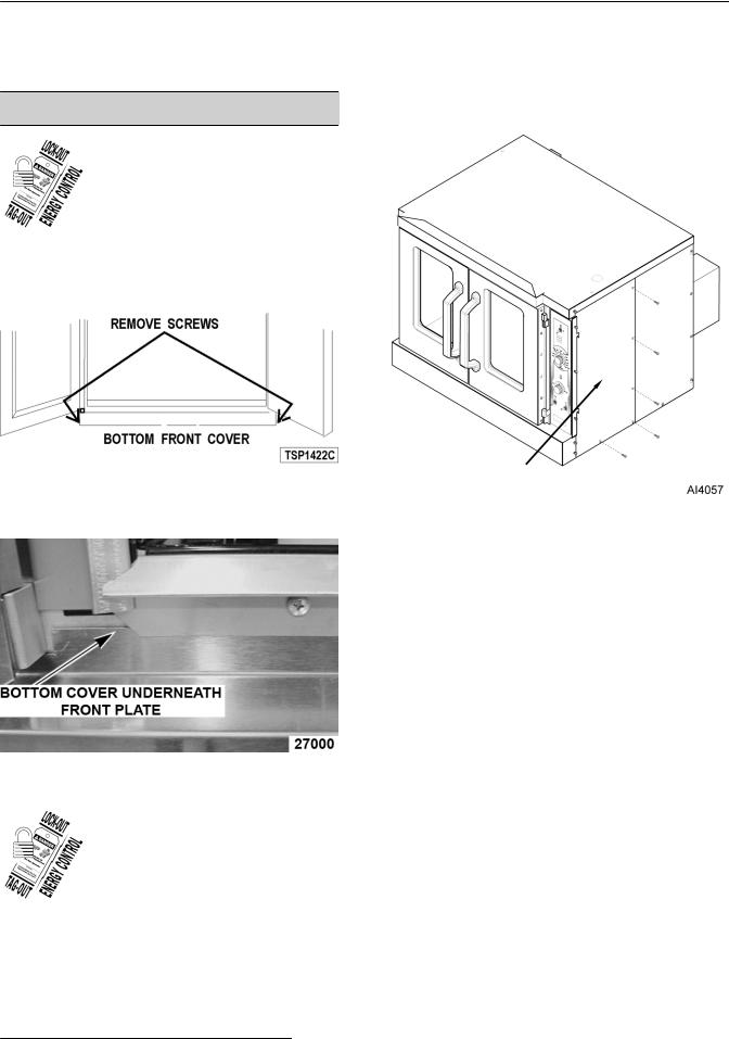
Bottom Front Cover
1.Remove four screws, two from each side of bottom cover, then remove cover from oven.
3.Remove screws along right side and bottom of front panel.
Fig. 1
2.Reverse procedure to install. Verify bottom cover is seated under front plate.
Fig. 2
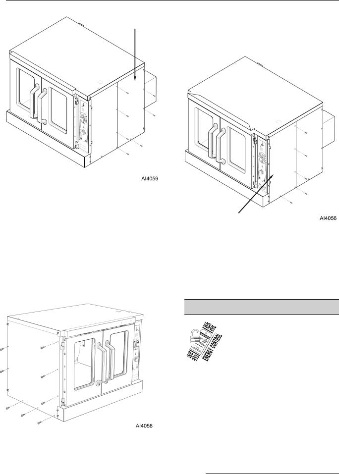
Right Side - Front Panel
 Disconnect the
electrical power to the machine and follow lockout / tagout procedures.
1.Loosen two screws near front of oven, which secure bottom front cover.
2.Loosen screws on left side of front panel and top cover screw.
Fig. 3
4.Slide right side front panel out.
5.Reverse procedure to install.
Right Side - Rear Panel
1.Remove two middle screws along right side of rear panel.
2.Remove screws along left side of rear panel.
3.Remove bottom screws on rear panel.
4.Loosen top and bottom screw along right side of rear panel.
Page 5 of 35 |
|
F45598 (0616) |
|
FULL SIZE GAS CONVECTION OVEN - REMOVAL AND REPLACEMENT OF PARTS
Control Panel
1. Remove three screws on the right side which secure the control panel then left up and pull away.
Fig. 4
5.Slide right side rear panel up and to the right to remove.
6.Reverse procedure to install.
Left Side Panel |
Fig. 6 |
|
1.Remove screws along right side, middle left side, and bottom on left side panel.
2.Loosen screws on top and bottom on left side of panel.
3.Loosen two screws near front of oven, which secure bottom front cover.
2.Disconnect the temperature probe leads from the solid state temperature control.
3.Unplug the wire harnesses connector to control panel components.
4.Unplug Ground wire from control panel.
5.Reverse procedure to install.
CONTROL PANEL COMPONENTS
 Disconnect the
electrical power to the machine and follow lockout / tagout procedures.
1. Remove CONTROL PANEL.
2. Remove component being replaced.
3. Reverse procedure to install replacement component.
4. Check oven for proper operation.
Fig. 5
4.Lift up and pull away to remove.
5.Reverse procedure to install.
F45598 (0616) |
|
Page 6 of 35 |
|
FULL SIZE GAS CONVECTION OVEN - REMOVAL AND REPLACEMENT OF PARTS
Fig. 7
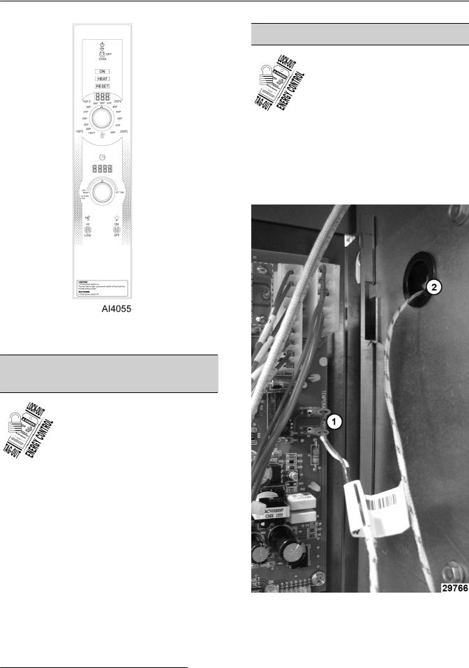
NOTE: Panel with standard controls shown.
COMPONENT PANEL
COMPONENTS
 Disconnect the
electrical power to the machine and follow lockout / tagout procedures.
1.Remove RIGHT SIDE PANEL.
NOTE: If right side panel is not accessible, this component can be service by removing the CONTROL PANEL.
2.Disconnect the wire leads to component being replaced.
3.Remove the component.
4.Reverse procedure to install component.
5.Check oven for proper operation.
TEMPERATURE PROBE
 Disconnect the
electrical power to the machine and follow lockout / tagout procedures.
1.Remove RIGHT SIDE PANEL.
NOTE: If right side - front panel is not accessible, this component can be serviced by removing CONTROL PANEL.
2.Disconnect the probe leads (1, Fig. 8) from the solid state temperature control.
Fig. 8
3.Remove the racks from inside cavity.
4.Remove the probe guard.
Page 7 of 35 |
|
F45598 (0616) |
|
FULL SIZE GAS CONVECTION OVEN - REMOVAL AND REPLACEMENT OF PARTS
Fig. 9
5.Remove probe by pushing it through the oven wall opening (2, Fig. 8) in control panel area.
6.Reverse the procedure to install the replacement probe.
7.Adjust the temperature control. Refer to: SOLID STATE TEMPERATURE CONTROL TEST .
GAS BURNER
 Disconnect the
electrical power to the machine and follow lockout / tagout procedures.
 Shut off the gas before servicing the unit.
1.Remove BOTTOM FRONT COVER.
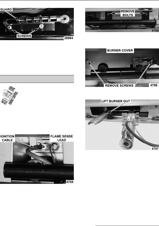
2.Disconnect ignition cable and the flame sense lead wire.
Fig. 11
4.Remove screws securing the burner cover and pull straight out.
Fig. 12
5.Grasp burner and lift out.
Fig. 13
6. Reverse procedure to install replacement burner.
NOTE: Ensure that burner positioning bracket (U- shaped end) is inserted into slot at the rear of burner chamber.
7. Check for proper operation.
Fig. 10
3.Remove bolts securing gas manifold to oven and place manifold to the side.
F45598 (0616) |
|
Page 8 of 35 |
|

FULL SIZE GAS CONVECTION OVEN - REMOVAL AND REPLACEMENT OF PARTS
GAS ORIFICE
NOTE: if right side panel is not accessible, this component can be serviced by just removing CONTROL PANEL.
 Disconnect the
electrical power to the machine and follow lockout / tagout procedures.
 Shut off the gas before servicing the unit.
1.Remove BOTTOM FRONT COVER.
2.Remove bolts securing gas manifold to oven and place manifold to the side.
Fig. 14
3.Remove gas orifice from spud on manifold and replace with correct orifice for the given altitude.
Fig. 15
4.Reverse procedure to install and check for proper operation.
GAS SOLENOID VALVE
 Disconnect the
electrical power to the machine and follow lockout / tagout procedures.
 Shut off the gas before servicing the unit.
1.Remove CONTROL PANEL and RIGHT SIDE FRONT PANEL.
2.Disconnect lead wires.
3.Disconnect compression fittings to valve.
Fig. 16
4.Loosen bolts securing valve and bracket assembly then remove screws securing valve to bracket.
Fig. 17
5.Reverse procedure to install replacement gas valve.
Page 9 of 35 |
|
F45598 (0616) |
|

FULL SIZE GAS CONVECTION OVEN - REMOVAL AND REPLACEMENT OF PARTS
NOTE: Clean pipe threads and apply pipe joint compound to threads. Any pipe joint compound used, must be resistant to the action of propane gases.
 All gas joints disturbed during
servicing must be checked for leaks. Check with a soap and water solution (bubbles). Do not use an open flame.
6.Verify gas pressure as outlined under GAS PRESSURE ADJUSTMENT.
7.Check for proper operation.
IGNITION CONTROL MODULE
 Disconnect the
electrical power to the machine and follow lockout / tagout procedures.
 Shut off the gas before servicing the unit.
1.Remove RIGHT SIDE FRONT PANEL.
NOTE: If right side panel is not accessible, this component can be serviced by removing CONTROL PANEL.
2.Disconnect lead wires (1, Fig. 18) and igniter cable (2, Fig. 18) from ignition module board.
Fig. 18
3.Remove the ignition module board from the mounting bracket.
4.Reverse the procedure to install replacement ignition module board.
SPARK IGNITER AND FLAME
SENSE
 Disconnect the
electrical power to the machine and follow lockout / tagout procedures.
 Shut off the gas before servicing the unit.
1.Remove GAS BURNER.
2.Remove screws securing ignitor and flame sense to burner, then remove assembly.
Fig. 19
3.Reverse procedure to install assembly and check for proper operation.
NOTE: Check to ensure spark gap distance is approximately 1/8". If gap appears to be excessive or poor sparking is occurring, then adjust.
Fig. 20
F45598 (0616) |
|
Page 10 of 35 |
|
FULL SIZE GAS CONVECTION OVEN - REMOVAL AND REPLACEMENT OF PARTS
BLOWER
 Disconnect the
electrical power to the machine and follow lockout / tagout procedures.
 Shut off the gas before servicing the unit.
Removal
1.Remove racks.
2.Lay cardboard on bottom of oven cavity to protect surface.
3.Remove snorkel (1, Fig. 21) and baffle panel (2, Fig. 21) mounting screws.
Fig. 22
5.Remove blower from motor shaft using a bearing puller.
Installation
1.Slide blower onto motor shaft until hub is protruding 1/8".
Fig. 21
4.Loosen set screws on blower hub.
Fig. 23
2.Tighten set screws ( Fig. 22) on blower hub.
3.Install snorkel (1, Fig. 21) and baffle panel (2, Fig. 21).
4.Install racks.
5.Check oven for proper operation.
Page 11 of 35 |
|
F45598 (0616) |
|
 Loading...