


SERVICE AND PARTS MANUAL
FOR ELECTRIC BAKE AND ROAST OVENS
MODELS V0004 & V0008
VULCAN-HART COMPANY, P.O. BOX 696, LOUISVILLE, KY 40201-0696, TEL. (502) 778-2791
FORM 30741 (9-92) (Formerly 112637)

SERVICE AND PARTS MANUAL |
|
ELECTRIC BAKE & ROAST OVENS |
|
MODELS V0004 & V0008 |
INDEX |
PLEASE KEEP THIS MANUAL FOR FUTURE REFERENCE
Your Vulcan oven is produced with quality workmanship and material. Proper installation, usage and maintenance will result in many years of satisfactory performance.
DESCRIPTION
The manufacturer suggests that you thoroughly read this entire manual and carefully follow all of the instructions provided.
PAGE
INDEX |
3 |
TROUBLESHOOTING |
4,5 |
|
|
CALIBRATING ELECTRIC CONTROLS |
6 |
|
|
PARTS DESCRIPTION AND REPLACEMENT |
7, 8 |
|
|
PARTS LIST |
9-22 |
|
|

TROUBLESHOOTING
The following is a guide for troubleshooting procedures and covers some of the more common problems that may develop. Servicing personnel need to become familiar with the circuit and components in order to follow a logical sequence of troubleshooting and to make repairs not mentioned in this troubleshooting guide.
Remember that the two 3 -heat switches control not only the rate of temperature build-up in the oven, but the amount of heat that is applied to their sections (top or bottom); therefore, the operator can control the needed heat for a particular meal by both its position inside the oven, as well as by varying the 3-heat switch setting.
The instruments required for troubleshooting are:
1.A.C voltmeter to measure line voltages up to 500 volts.
2.A.C. ammeter to measure line currents.
3.Accurate thermometer to measure temperature.
In the following table, the voltmeter is used to measure the voltage between two phases on 208, 240 and 480 volts, and between the phase and the neutral on 220/380 and 240/415 volt supplies. Do not measure the voltage with respect to the chassis ground. For the sake of simplicity, the measured voltage is referred to 208 volt, assuming that the supply is 208 volt. When the supply is 220, 240 or 480 volt, the measured voltage should also be 220, 240, 480 volts. Refer to the appropriate wiring diagram for reference.
The fact that the voltmeter indicates presence of voltage does not mean that the current is flowing. To be sure of optimum function, an ammeter should be used to determine the exact amount of current going through the elements. Check the supply current going to X, Y, or Z terminals and compare it with the required value shown on the wiring diagram or the rating decal (attached to the breaker cover) for the particular supply voltage and phase.
With the main power ON, 3-heat switches set at HI, and the thermostat set at about 400°F:
PROBLEM |
CORRECTIVE ACTION |
|
|
No heat in any sections. |
Check the main supply breaker or fuse. |
No heat in one section only. |
Check voltage on the terminal block of the cool section. Follow 1 or 2 |
|
below. |
|
1. If no voltage, check for loose or wrong connection of the interconnecting |
|
leads. |
|
2. If 208 volt, check, voltage between lead 3 and 6 or A3. Follow A or B |
|
below. |
|
A. If no voltage, check for bad connection to, or a tripped or failed |
|
circuit breaker. |
|
B. If 208 volt, measure voltage between 6 and 12 and between A3 and |
|
11. If no voltage, check the thermostat. If 208 volt, check the |
|
voltage between terminals 2 and 1 of the 3-heat switch (set the |
|
switch on HI position). If no voltage, check for problem with the |
|
switch. If 208 volt, check the elements for either open circuit or bad |
|
connection. |
|
|
Heat in bottom section only. |
Measure voltage between L2 and L3 terminals of the top 3 -heat switch. |
|
Follow 1 or 2 below. |
|
1. If 208 volt, measure voltage between terminals 2 and 3 of the switch |
|
(with switch set on HI position). Follow A or B below: |
|
A. If no voltage, replace switch. |
|
B. If 208 volt, check for opened elements or bad connection in leads |
|
17,18,19. |
|
2. If no voltage, check the thermostat and supply voltage as outlined in NO |
|
HEAT IN ONE SECTION ONLY above. |
|
|
PROBLEM |
CORRECTIVE ACTION |
|
|
Heat in top section only. |
Follow the same procedure for the bottom 3 -heat switch as outlined in HEAT |
|
IN BOTTOM SECTION ONLY above. |
|
|
Oven temperature not |
Recalibrate the thermostat, following the instructions in RECALIBRATING |
|
ELECTRIC CONTROLS in this manual. |
No oven lights (all models |
Since the two 25 watt, 120 volt bulbs are connected in series to the 208-240 |
except pizza oven). |
volt supply, a problem with either bulb will result in no lights. Replace both |
|
bulbs with two good ones. Make sure the bulbs are tight inside the socket. |
|
If still no light, measure the voltage between leads 4 and 8 going to the |
|
switch. |
|
If 208 volt, check for problem with switch or bad connections to the switch |
|
and to the lamp sockets . |
|
If no voltage, proceed as follows: |
|
208 volt models: Check for problem with breakers or bad connections to |
|
breakers. |
|
480 volt models: Measure voltage between leads 4 and 31. |
|
1. If 230 volt, check for problem with the breaker. |
|
2. If no voltage, measure voltage between lead 32 and the transformer |
|
lead connected to the end terminal of the breaker. |
|
A. If 480 volt, check for problem with transformer. |
|
B. If no voltage, measure between leads 32 and 33 on the breaker |
|
terminal. If 480 volt, the breaker is bad. If no voltage, check for |
|
bad connection to the terminal block. |
CALIBRATING ELECTRIC CONTROLS
Robertshaw electric thermostats are adjusted at the factory and calibrated on precision instruments to control temperatures accurately. Adjustment or recalibration is not needed unless the thermostat has been mishandled in transit, or changed or abused while in service.
TO CHECK CALIBRATION
1.Use a Robertshaw test instrument or a good grade oven thermometer and place thermocouple or thermometer in center of oven.
2.With thermostat dial in the OFF position, make certain OFF mark on the dial agrees with reference point of the bezel or panel; misalignment will affect calibration. Then turn the dial to a medium temperature setting.
3.Allow oven to heat until control snaps ON and OFF thermostatically at least three times. This will allow oven temperature to stabilize and eliminate possible error resulting from initial oven temperature overshoot and/or undershoot.
4. After the control has cycled thermostatically three or more times, note the oven temperature when the electric unit snaps off, and the oven temperature when it snaps on. Recalibrate only if the average of these two temperature readings varies more than ±20°F of the dial setting.
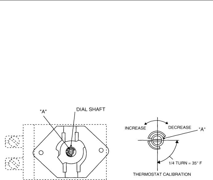
TO CALIBRATE
5.Turn control to OFF position and remove dial.
6.With screwdriver, turn screw "A" clockwise to decrease and counterclockwise to increase the temperature. A 1/4 turn
of screw "A" causes a temperature shift of 35°F (Fig. 1).
7. Replace dial.
After calibration is made, allow oven to operate until temperature has stabilized, then recheck to determine whether or not the calibration has been corrected.
PL-501 119|
Fig.1

PARTS DESCRIPTION AND REPLACEMENT
WARNING: DISCONNECT ELECTRICAL POWER SUPPLY BEFORE SERVICING.
Reconnect the leads to the replaced component exactly as to the original (refer to the wiring diagrams for each model).
SWITCH PANEL
Thermostat
A DPST cycling switch, with its normally closed contacts, provides power to the two non-cycling 3-heat switches, which, in turn, turns on the heating elements. Once the set temperature is reached, the contacts open and the elements are turned off. The thermostat used in pizza ovens has a maximum temperature limit of 700°F. The thermostat used in all other models has a limit of 500°F.
To replace the thermostat, remove the bulb from under the mounting clips inside the oven. Pull out the capillary through the hole on the right-hand oven wall, loosen the two mounting screws of the thermostat, and remove it from the switch panel.
To recalibrate the thermostat, follow the instructions in CALIBRATING ELECTRIC CONTROLS in this manual.
3-Heat Switch
A double-pole, 4-position switch connects the supply power at its input (L2, L3 terminals) to the elements at its output (terminals 1, 2, 3) in such a way as to provide full power (elements connected in parallel) to about half of full power (only one element connected) to about one-fourth of full power (elements connected in series) as it rotates from HI to MED to LO positions. At the OFF position, all connections are opened. Therefore, the position of the 3-heat switch determines the rate of temperature rise, while the thermostat controls the temperature limit. The 3-heat switches used in 208-240 volt and 480 volt models, though physically looking different, electrically are identical. The following diagrams show the proper connection for each model:
HI position: |
L2 connects with 2 |
|
L3 connects with 1 & 3 |
MED position: |
L2 connects with 2 |
|
L3 connects with 1 |
LOW position: |
L2 connects with 3 |
|
L3 connects with 1 |
OFF position: |
All connections open |
To remove the switch, loosen the nut on the shaft and pull it out from the back of the switch panel.
Signal Light
The light ON indicates that the thermostat contacts are closed, providing power to the 3-heat switches. The light goes off when the set temperature is reached. While maintaining at set temperature, the light cycles on and off.
To replace the bulb, unscrew and remove the lens to reach the bulb.
To replace the socket assembly, loosen and remove the nut in the back of the switch panel, then pull the socket out from the front.
NOTE: On 480 volt models, make sure that a 300K ohm resistor is added in series with the light.
To replace bulbs, remove the four screws mounting the window assembly to the oven wall.
NOTE: Make sure that the bulb is 25 watt and the gasket is in good condition.
Element Assembly
The inner and outer elements in the top or bottom section of the oven are connected together by a jumper strap on one end (common junction, connected to terminal 2 of the 3-heat switch). The voltage and wattage rating is stamped on each element (see wiring diagrams for detail).
Replace the elements from inside the oven as follows:
1. Top Elements
Remove the element terminal cover and loosen the bolts and nuts to disconnect the end straps from the element terminals. Remove the retainers holding the elements to the frame and slide the element out of the frame assembly.
2. Bottom Elements
Remove the oven hearth by removing the three slotted head bolts. Lift front of the hearth and pull it out of the oven. To replace the elements, follow the same procedure described in Item 1 above.
Connection Block Assembly
1. 208 and 240 Volt Models
Remove the breaker closure in order to reach the components.
A. Terminal Block—Used for interconnecting or field supply leads. To replace, remove the two mounting screws.
B.Porcelain Block — Used as a junction for wires going to the oven lights.
C.Breakers — The 15 amp. breakers protect the lights and thermionic (fan) circuit. The 50 amp. breakers protect the heating elements. To
replace, remove the two mounting screws.
2. 480 Volt Model
Remove the breaker closure in order to reach the components.
A. Terminal Block — Used for field or interconnecting supply leads. To replace, remove the two mounting screws.
B.Porcelain Block — Used as a junction for wires going to the oven lights.
C.Breaker — The coil of the relay trip breaker is connected in series with the primary of the control transformer, and the switches of the
breaker are connected in series with the secondary winding of the transformer. Overload in the coil of the breaker causes the switch to trip open, turning off the control circuit (secondary of the transformer).
To replace, remove the two mounting screws.
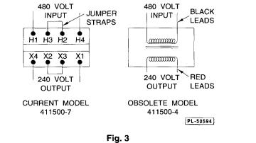
D. Transformer — The 460 to 230 volt, 200 VA control transformer steps down the supply voltage for the oven light circuit.
To replace, remove the four mounting screws.
NOTE: When replacing the transformer, make sure that terminal H2 is connected to H3 and terminal X2 to X3 by means of the metal jumper strap or jumperwire lead. ConnecttoH"! andH4 terminals (primary or input) the 480 volt supply leads, and connect to X1 and X4 terminals (secondary or output) the 240 volt leads for the light circuit. See the 480 volt wiring diagrams for
detail.
Timer
Remove the knob and the lockwasher from outside the oven. Remove the timer body from inside the control compartment.
 Loading...