


INSTALLATION, SERVICE AND
PARTS MANUAL FOR
ET4 ELECTRIC HALF SIZE
CONVECTION OVEN
VULCAN-HART COMPANY, P 0. BOX 696, LOUISVILLE, KY 40201 -0696, TEL. (502) 778-2791

 IMPORTANT
OPERATING, INSTALLATION AND SERVICE PERSONNEL
Operating information for this equipment has been prepared for use by qualified and/or authorized operating personnel
All installation and service on this equipment is to be performed by qualified, certified, licensed and/or authorized installation or service personnel, with the exception of any marked with a ? in front of the part number
Service may be obtained by contacting the Factory Service Department, Factory Representative or Local Service Agency
DEFINITIONS
QUALIFIED AND/OR AUTHORIZED OPERATING PERSONNEL
Qualified or authorized operating personnel are those who have carefully read the information in this manual and are familiar with the equipments functions or have had previous experience with the operation of the equipment covered in this manual
QUALIFIED INSTALLATION PERSONNEL
Qualified installation personnel are individuals, a firm, corporation or company which either in person or through a representative are engaged in, and are responsible for
1.The installation of gas piping from the outlet side of the gas meter, or the service regulator when the meter is not provided, and the connection and installation of the gas appliance Qualified installation personnel
must be experienced in such work, be familiar with all precautions required, and have complied with all requirements of state or local authorities having jurisdiction Reference in the United States of America - National Fuel Gas code ANSI Z223 1 (Latest Edition) In Canada-Canadian Standard CAN1-B149 1 NAT GAS (Latest Edition) or CAN1-B149 2 PROPANE (Latest Edition)
2.The installation of electrical wiring from the electric meter, main control box or service outlet to the electric appliance Qualified installation personnel must be experienced in such work, be familiar with all
precautions required, and have complied with all requirements of state or local authorities having jurisdiction Reference In the United States of America-National Electrical Code ANSI NFPA No 70 (Latest Edition) In Canada-Canadian Electrical Code Part 1 CSA-C22 1 (Latest Edition)
QUALIFIED SERVICE PERSONNEL
Qualified service personnel are those who are familiar with Vulcan equipment who have been endorsed by the Vulcan-Hart Corporation All authorized service personnel are required to be equipped with a complete set of service parts manuals and stock a minimum amount of parts for Vulcan equipment
SHIPPING DAMAGE CLAIM PROCEDURE
For your protection, please note that equipment in this shipment was carefully inspected and packed by skilled personnel before leaving the factory. The transportation company assumes full responsibility for safe delivery upon acceptance of this shipment
If shipment arrives damaged:
1.VISIBLE LOSS OR DAMAGE — Be certain this is noted on freight bill or express receipt and signed by person making delivery
2.FILE CLAIM FOR DAMAGES IMMEDIATELY — Regardless of extent of damage
3.CONCEALED LOSS OR DAMAGE — If damage is unnoticed until merchandise is unpacked, notify transportation company or carrier immediately, and file "concealed damage" claim with them This should be done within (15) days of date of delivery is made to you Be sure to retain container for inspection
We cannot assume responsibility for damage or loss incurred in transit We will, however, be glad to furnish you with necessary documents to support your claim
PLEASE RETAIN THIS MANUAL FOR FUTURE REFERENCE

IMPORTANT NOTES FOR ALL VULCAN APPLIANCES
1.These units are produced with the best possible workmanship and material. Proper installation is vital if best performance and appearance are to be achieved. Installer must follow the installation instructions carefully.
2.Information on the construction and installation of ventilating hoods may be obtained from the “Standard for the installation of
equipment for the removal of smoke and grease laden vapors from commercial cooking equipment,” NFPA No 96 (latest edition) available from the National Fire Protection Association, Battery March Park Quincy MA 02269.
3.For an appliance equipped with a flexible electric supply cord, the cord is equipped with a three prong (grounding) plug. This grounding plug is for your protection against shock hazard and should be plugged directly into a properly grounded three-prong receptacle. Do not cut or remove the grounding prong from this plug If the appliance is not equipped with a grounding plug, and electric supply is needed, ground the appliance by using the ground lug provided (refer to the wiring diagram).
(FOR GAS APPLIANCES ONLY)
4.Do not obstruct the air flow into and around the appliance This air flow is necessary for proper combustion of gases and for ventilation of the appliance Provisions for ventilation of incoming air supply for the equipment in the room must be in accordance with National Fuel Gas Code ANSI Z223 1 (latest edition)
5.Do not obstruct the flow of flue gases from the flue duct (when so equipped) located on the rear (or sides) of the appliance. It is recommended that the flue gases be ventilated to the outside of the building through a ventilation system installed by qualified personnel.
6 For an appliance equipped with casters, (1) the installation shall be made with a connector that complies with the Standard for Connectors for Movable Gas Appliances, ANSI Z21. 69 (latest edition), and Addenda, Z21.69a (latest edition), and a quickdisconnect device that complies with the Standard for Quick-Disconnect Devices for Use With Gas Fuel, ANSI Z21. 41 (latest edition), and Addenda, Z21. 41 a (latest edition) and Z21. 41 b (latest edition) and (2) adequate means must be provided to limit the movement of the appliance without depending on the connector and the quick-disconnect device or its associated piping to limit the appliance movement If disconnection of the restraint is necessary, reconnect this restraint after the appliance has been returned to its originally installed position.
7The appliance and its individual shutoff valve must be disconnected from the gas supply piping system during any pressure testing of that system at test pressures in excess of 1/2 psig (3.45 k Pa)
8The appliance must be isolated from the gas suppiy system by closing its individual manual shutoff valve during any pressure testing of the gas supply system at test pressures equal to or less than 1/2 psig (3 45 k Pa)
CAUTIONS
FOR YOUR SAFETY
DO NOT STORE OR USE GASOLINE OR OTHER FLAMMABLE VAPORS AND LIQUIDS IN THE VICINITY OF THIS EQUIPMENT OR ANY OTHER APPLIANCE.
1.KEEP THE APPLIANCE FREE AND CLEAR FROM ALL COMBUSTIBLE SUBSTANCES.
2.IN THE EVENT A GAS ODOR IS DETECTED, SHUT UNIT(S) DOWN AT THE MAIN
SHUTOFF VALVE AND CONTACT THE LOCAL GAS COMPANY OR GAS SUPPLIER FOR SERVICE.
3. POST IN A PROMINENT LOCATION, INSTRUCTIONS TO BE FOLLOWED IN THE EVENT THE SMELL OF GAS IS DETECTED. THIS INFORMATION MAY BE OBTAINED FROM A LOCAL GAS SUPPLIER.

|
INSTALLATION, SERVICE & PARTS MANUAL FOR |
|
|
|
|
ET-4 ELECTRIC HALF SIZE CONVECTION OVEN |
INDEX |
|
|
|
|
|
|
|
|
All Vulcan equipment is produced with the best possible |
The manufacturer suggests that this entire manual be |
|
|
|
workmanship. Proper usage and maintenance will result in |
thoroughly read and all instructions provided within be carefully |
|
|
|
many years of satisfactory performance. |
followed. |
|
|
DESCRIPTION |
PAGE |
|
DEFINITIONS OF PERSONNEL (Installation, Service & Parts) |
(Inside Front Cover) |
|
and SHIPPING DAMAGE CLAIM PROCEDURES |
||
|
||
|
|
|
IMPORTANT NOTES |
116021-1 |
|
|
|
|
INDEX |
116021 - 2 |
|
|
|
|
CAUTIONS |
116021-2 |
|
|
|
|
INSTALLATION INSTRUCTIONS |
116021-3 |
|
|
|
|
GENERAL THEORY OF OPERATION |
116021-3 |
|
|
|
|
OPERATING INSTRUCTIONS |
116021-4 |
|
|
|
|
PREHEATING, LOADING, UNLOADING & CLEANING |
116021-5 |
|
|
|
|
COOKING CHART |
116021-5 & 6 |
|
|
|
|
OPERATORS TROUBLE SHOOTING |
116021-7 |
|
|
|
|
SERVICE PERSONNEL TROUBLE SHOOTING |
116021-8 & 9 |
|
|
|
|
PARTS DESCRIPTION AND REPLACEMENT |
116021 - 9 thru -11 |
|
|
|
|
REPLACEMENT PARTS LIST & PHOTOGRAPHS |
116021 - 12 thru -17 |
|
|
|
|
REVISION PAGE |
(Inside Back Cover) |
|
|
|
CAUTIONS AND NOTATIONS
NOTE:
A complete set of wiring diagrams are packaged in a separate envelope and sent out with the unit. A wiring diagram decal may also be found on the back of the unit next to the electrical supply line.
OPENING OVEN DOOR:
Opening oven door will automatically cut "off" fan and heating elements. However, hot air gathered within the oven cavity may be thrusted outwards when the door is opened.
CAUTION:
DO NOT stand directly in front of oven while opening door.
When opening door, operator should pull handle outward while simultaneously stepping back away from the front of the unit.
Load oven as quickly as possible to conserve heat. Center pans on racks.
NOTE:
All Vulcan electric convection ovens are equipped with an electrical rating plate indicating unit model number, serial number, unit voltage, motor volts, motor amps, unit phase and heater kilowatts. The rating plate may be found mounted on the cover of the terminal box located to the lower right hand corner of body back when facing unit from the front.
116021-2
INSTALLATION INSTRUCTIONS
Vulcan electric convection ovens are U.L. listed under file number E75870 and are manufactured for use on electrical service of the characteristics specified on the rating plate. For proper installation procedures in the United States of America, refer to: National Electrical code (ANSI/ N F P A No. 70 (latest edition) Information on the construction and installation of ventilating hoods may be obtained from the "Standard For The Vapors From Commercial Cooking Equipment", N. F. P. A. No 96 (latest edition) available from The National Fire Protection Association “Attention Publication Services", Battery March Park, Quincy, MA 02269
NOTE: This equipment is design certified by a nationally recognized testing laboratory to the appropriate national standards as indicated on the equipment rating plate. Any modification made without written permission of Vulcan-Hart Corporation voids the certification and warranty of this unit. Units designed for 208 or 240 volts will operate satisfactorily within the voltage range of 197 to 218 and 228 to 252 volt A C respectively Units designed for 220/380 or 240415 volt AC require voltage supplies with ground and neutral (3-phase, 4- wire, or 1-phase, 3-wire)
Units wired for three(3) phase service may be changed to single phase or single phase units may be changed to three (3) phase as shown on the wiring diagram and connection decal (Except for 3-phase motor construction )
1.Remove crating with care. Remove all wood blocking, packing, material and accessories.
2.Unit has been factory equipped and electrically connected for
use with the specific electric supply indicated on rating plate. Check electric supply available. If the two voltages don't agree, contact your dealer or Vulcan-Hart immediately without proceeding to the next step.
3.Install unit in final position if this was not done while making connection.
4.Using a carpenter's level placed on oven rack, adjust the
feet on the bottom of each leg, so that oven is level from front to back and side to side. (NOTE: Level oven when in permanent position only )
5.Bring the conduit containing the proper size field supply wires (select the size and type of the field wires in accordance with National Electric Code, suitable for carrying the equipment's rated amps and voltage. For equipment rated over 100 amps, 75°0 field wires must be used) to back
of the unit through the l13-/32” hole provided in body back and connect the phase leads (as well as neutral lead in 220/380 or 240 /415 volt A. C. units) to the field terminal block identified by X, Y Z sections, and connect the green grounding lead to the labeled ground lug Oven should now be ready for operation To place the unit in operation, simply push the master switch to the 'on" position and set the thermostat to the desired position (See operating instructions for further details )
NOTES: In 220/380 or 240/415 A.C. models, the oven operates on either 220 or 240 volts between the neutral wire, independent from the grounding wire which is used to ground the oven frame for safety reasons, is included in the main supply leads.
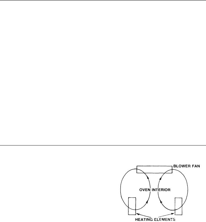
GENERAL THEORY OF OPERATION
Figure 8.0 Air Flow Pattern: Shows the air flow pattern inside the Vulcan-Hart Half Size Convection Oven The blower pulls the air from inside the oven cavity and forces it toward the front and back of the cavity. The forced air is then deflected through the fan cover, towards the left side of the oven in both the front and back. The air carries the heat from the heating elements located behind the fan cover and distributes it throughout the oven cavity. In general, the blower operates continuously, while the thermostatically controlled heating elements (3 elements) are energized only when there is a demand for heat and de-energize when the desired temperature is reached.
A PLunger action door switch, mechanically linked with the door shuts off both the heat and the blower when the door is opened and will automatically reset when the door is eluded.
In the parts description and replacement section in the installation, service and parts manual, the detailed function of each component is explained.
FIG. NO. 8.0 AIR FLOW
PATTERN
116021-3

OPERATING INSTRUCTIONS
WARNING: The oven is hot. Use care when operating and cleaning the oven.
GENERAL
The Vulcan method of air circulation and the thermostat make possible the Vulcan system of controlled convection cooking. This system lets you adjust the oven for the product result you desire from your recipes.
AIR CIRCULATION
The ET4 oven cavity shall be direct heated by (3) independent oven elements rates at 2,000 watts each for a total input of 6,000 watts. Heated air is circulated over the oven elements by a 9 5/32" diameter airotor. The heated air is then delivered to the oven cavity via the fan cover and the air flow scoops to the top and bottom of the oven cavity. After circulating throughout the oven cavity, the air is drawn through the center opening of the fan cover and the process is repeated.
CONTROLS
The thermostat controls the temperature that the air in the oven will reach and cuts the heating elements off when air is at the thermostat setting.
RECIPE ADJUSTMENT
The oven does not require special recipes. Excellent results can be obtained from any good commercial recipe with reduced cooking times.
TEMPERATURE ADJUSTMENT
The oven will cook or bake full or partial loads at standard recipe temperatures when the thermostat is properly set. As with any oven, you may wish to use a temperature of up to 25° higher or lower than the recipe for the particular product result that you prefer.
USE OF CONTROLS:
1.Master Switch - Item 1
The main on-off switch connects and disconnects the electric supply to the unit controls, turning the unit "on and off".
2.Thermostat - Item 2
The thermostat is a snap-acting on-off type control. The thermostat regulates the oven temperature from 150° through 450°. Turn dial clockwise to increase temperature and counterclockwise to decrease temperature.
NOTE: All heating elements are under supervision of the thermostat.
3.Timer - Item 3
The one hour timer is graduated in one minute increments. Turn dial clockwise to increase time and counterclockwise to decrease time.
4.Thermostat Light - Item 4
When the thermostat light is "on" it indicates that the oven is pre-heating or has not recovered to the dial temperature setting during a cooking cycle.
116021-4

PREHEATING, LOADING, UNLOADING & CLEANING (STANDARD AND ROAST & HOLD OVENS)
Set the timer to the required time (see separate cooking chart). When the preset time is up, the timer buzzer will sound, turn the timer pointer to the "hold" position which is to the left of the "0" minute mark.
Check the product for proper consistency and unload, or set for additional time as required.
UNLOADING (See Caution Page)
Arrangements should be made so that adequate counter space is available for the products to be unloaded from the oven Rapid unloading will conserve heat, and this is essential if you are reloading for high production. On multiple loading, close the doors between each load and allow the oven to recover its preset temperature. Unloading is easier if the racks are pulled forward for better access to the pans; or if a bakers peal is used.
CARE AND CLEANING
Stainless steel oven front may be cleaned with a damp cloth. Stubborn soil may be removed with detergent. (Do Not Use
"Dawn".)
CAUTION: Scouring power should not be used except with great care. Scouring powder is extremely difficult to remove completely. It can build up accumulations that will damage the oven. It will scratch and fog glass and can even damage and remove corrosion resistant finishes.
Nickel plated racks and rack supports may be removed for cleaning.
The fan cover is also removable for cleaning. Normally this is not necessary, but will be helpful if batter or liquid is accidently spilled into the fan area. It is recommended that fan cover be removed at least twice yearly in order to remove debris trapped behind the linings.
After processing some foods at low temperatures, odors may linger in the oven. These odors may be cleared by setting the thermostat at 450°F., then allow the oven to operate unloaded for 30 to 45 minutes.
REQUIRED LUBRICATION
Motor bearings are packless, sealed and lubricated for life.
COOKING CHART
IMPORTANT
Recommended temperatures, times and number of racks are intended as a guide only. Adjustments must be made to compensate for variations in recipes, ingredients, preparation and personal preference in product appearance.
RECOMMENDED TEMPERATURES AND TIMES FOR ROASTING
Meat roasting is most satisfactory at temperatures of 225° to 325°F for beef, lamb, poultry and ham; 325°F for fresh pork as recommended by USDA and American meat Institute.
A pan full of water may be placed in the oven bottom. This water supplies humidity to reduce shrinkage. Water should be added if necessary during roasting.
Roasting pans should be no deeper than necessary to hold drippings, usually 2" to 2 1/2".
Cooking time and shrinkage may vary with roasting temperature, cut and grade of meat and degree of doneness. Smaller cuts will generally show greater time savings than large cuts at a given temperature.
RECOMMENDED TEMPERATURES & TIMES FOR ROASTING
ROASTING TEMPERATURE CHART |
TEMPERATURE |
APPROXIMATE TIMES |
|
PRODUCT |
|||
|
|
||
|
|
|
|
Standing Rib |
250°F |
3 to 4 hours-rare |
|
Roasts - oven ready |
4 to 4 1/2 hours-medium |
||
|
|||
Rolled Rib Roasts |
275°F |
4 hours-medium |
|
20to22lbs. |
|||
|
|
||
Veal Roast-15 Ibs. |
300 F |
4 hours - medium well |
|
Turkeys-15 to 20 Ibs |
300°F |
3 hours |
|
Meat Loaf-8to10 Ibs. |
350°F |
45 to 60 minutes |
 Loading...