

Page 1
INTRODUCTION
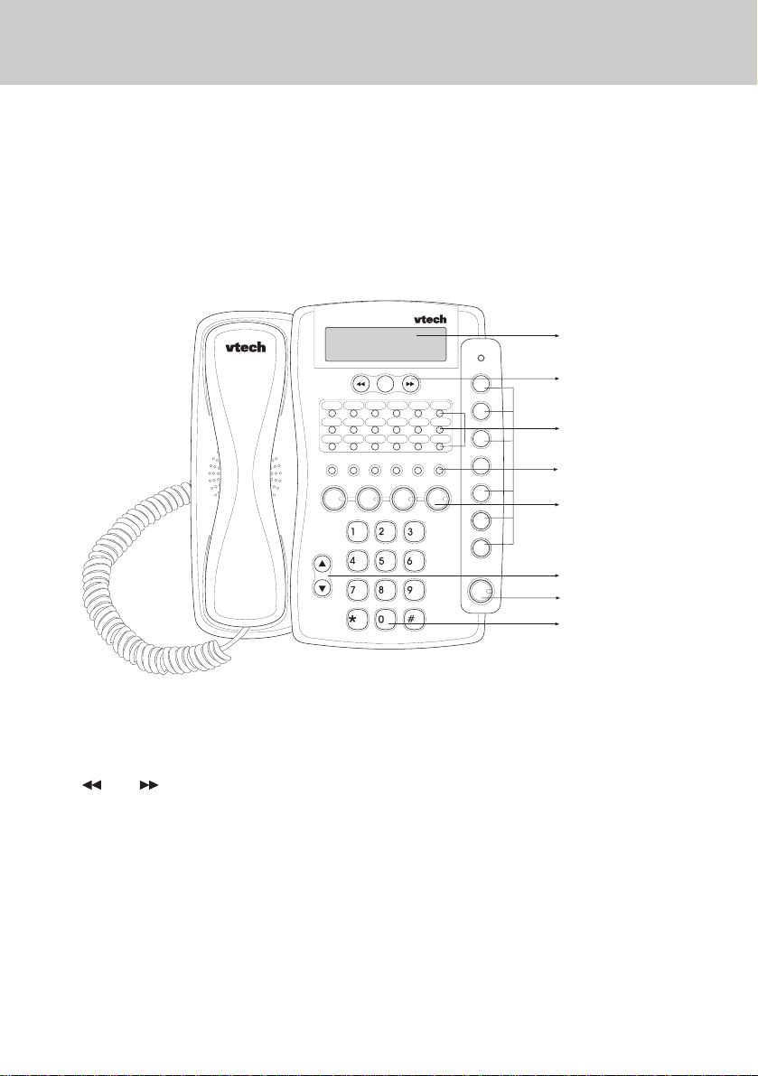
1. Becoming Familiar With Your Speakerphone
Congratulations! You have purchased one of the best performing 4-line speakerphones on the market!
This manual is designed to familiarize you with the VT 4121. To get the most use out
of your VT 4121, we strongly recommend you read the manual before using your
phone.
DISPLAY
CALLER ID BUTTONS
SPEED DIAL BUTTONS
FUNCTION BUTTONS
LINE BUTTONS
VOLUME UP & DOWN BUTTON
SPEAKERPHONE BUTTON
DIAL PAD BUTTONS
Display and Function Buttons:
and keys
• Allow you to scan through the caller
ID list.
CID
• Allows you to review calls in caller
ID memory.
END
• Used to exit the programming mode.
ERASE
• Enables you to erase a programmed
setting.
DND
• Used to place your telephone in Do
Not Disturb mode.
DIAL
• Used to dial a telephone number
from the caller ID list.
1
Page 2

INTRODUCTION
PAGE
• You can page an individual extension.
PAGE ALL
• Y ou can page all speak erphones simultaneously .
LINE Buttons
• Allow access for up to four (4) lines.
ICM
• Used to place an intercom call.
MUTE (ENTER)
• Mutes the microphone so the dis-
tant party can’t hear you. Also used
as “enter” during programming.
PROGRAM
• Used to define various features settings.
VOLUME
• Adjusts the ringing, receiver, and
speaker volumes.
CONFERENCE
• You can establish a 3-way conference.
HOLD
• Enables you to place a line on hold
or transfer the line.
2. The display
Your telephone is equipped with a wide
angle viewing “supertwist” display. The
2-line by 16 character dot matrix liquid
crystal display indicates the current
time, day, date, and extension number.
A call duration timer appears automatically to time your calls. The telephone
number that you dial is displayed. You
can also view caller ID information for
an incoming call, provided that you are
subscribing to Caller ID service from
your telephone company.
JAN 21 SA 11:35A
EXT 12
JAN- The month of the year.
21- The date of the month.
SA- The day of the week.
11:35A- The time of day.
EXT- Your extension number.
3. The Features
FLASH
• Programmable from 0.1 second to
1.2 seconds.
REDIAL (PAUSE)
• Redials the last number dialed from
the telephone. Also used to insert a
pause into a dialing sequence.
SPEAKER
• Allows you to speak hand free. Also
controls headset use.
Your VT 4121 4-line speakerphone pro-
vides many features such as:
Caller ID
• The caller’s name and number and
the time and date of the call will be
displayed on the Speakerphones.
(Y ou will need to subscribe to Caller
ID service provided by your local
telephone company for each telephone line you want caller ID information displayed.)
2
Page 3
INTRODUCTION
Caller ID Log
• Up to 99 telephone numbers will be
stored in the Caller ID Log for review, redial, save to speed dial or
deletion.
Message Waiting Indicator
• Message LED will indicate presence
of network based voice messages.
(You will need to subscribe to the
Voice Messaging ser vice provided
by your local telephone company.)
Desktop Data Port
• Modular desktop connection for
single line devices to line four (modem, fax, answering machine, etc.)
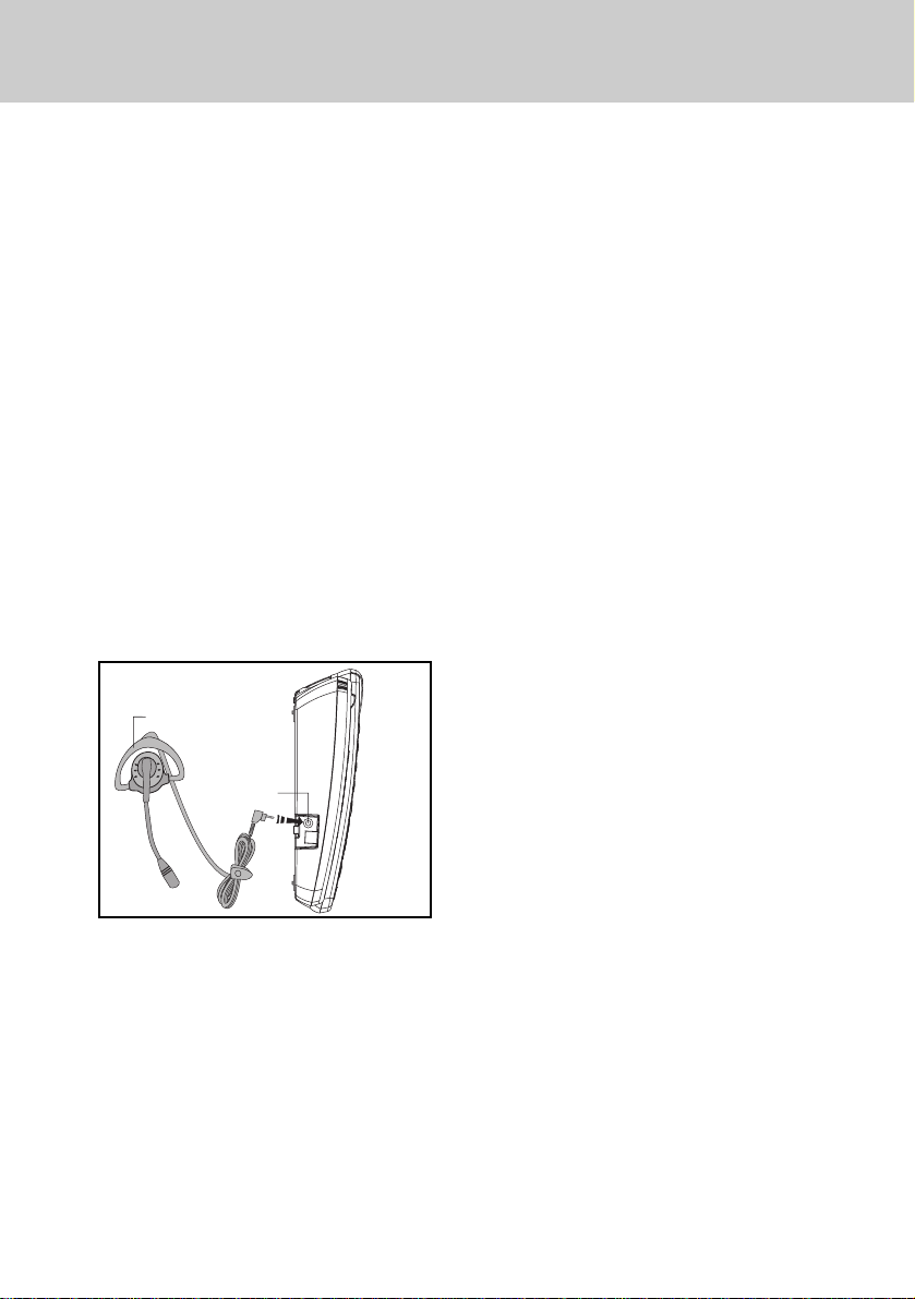
Headset Jack
• 2.5 mm jack for connecting an optional telephone headset for hands
free communications.
OVER THE EAR HEADSET
HEADSET JACK
Four (4) CO Lines with Line Status
Indication
• You can connect up to 4 lines. The
lamps will light to indicate the status of the lines.
Line-In-Use Detection of Other Connected Telephones ( fax, modem,
etc.)
• A line lamp will light to indicate that
the line is busy. This helps to prevent accidental line pick-up interruptions.
Automatic Line Selection
• You can designate a line to be automatically accessed whenever you
lift the handset or press the speakerphone button.
Distinctive Ringing
• Choose from four (4) unique ring
tones to easily identify calls ringing
at your telephone.
Delayed Ringing
• You can delay the ringing of a line
for overflow call coverage.
Handsfree Speakerphone
• This feature enables you to conduct
telephone conversations handsfree.
Supertwist 2 x 16 Dot Matrix Liquid
Crystal Display
• The display shows useful information such as the current time, and
date, as well as a number dialed and
the call duration.
Adjustable Ringer, Receive and
Speaker V olume Levels
• You can adjust the volume levels to
suit your own preferences.
Intercom with Direct Station Select
Buttons
• You can call another extension with
the touch of one button.
Intercom Call Pick-Up
• Any telephone can answer an intercom call ringing at another extension.
3
Page 4

INTRODUCTION
Page
• You can voice page all extensions
or perform a single page to a telephone. Meet-Me-Ans wer allows you
to answer an All Page from an y telephone. A utomatic Mute may be programmed to prevent sounds in y our
room from being heard while someone makes a single page to you.
Hold with Reminder
• When you place a call on Hold you
will hear a tone every thirty (30) seconds to remind you that the call is
on Hold.
Call Privacy with Release
• When you are using an outside line,
another person cannot join your
conversation on that line unless you
release Call Privacy.
Conference
• You can establish a 3-way conversation with any two outside parties
or with one outside party and one
other extension.
Call Forward to Other Speakerphones
• You can forward your calls to another speakerphone (VT 4121 only).
Call T ransfer
• You can transfer a call to another
extension.
Auto Busy Redial
• The telephone will automatically redial the last number dialed from the
telephone, up to ten (10) attempts.
This feature is useful when you are
trying to call a busy telephone number.
Last Number Redial
• The telephone will automatically re-
dial the last number dialed from the
telephone (up to 32 digits) with the
touch of one button.
Speed Dialing
• You can store up to eighteen (18)
frequently dialed telephone number
which can be dialed by pressing one
button.
Mute (Enter)
• While on a call, if you want to have
a private conversation with someone in the room, you can mute the
telephone’s microphone so the distant party cannot hear you. The Enter feature is used during programming.
Do Not Disturb
• You can prevent interruptions from
incoming calls, intercom calls, and
pages by activating Do Not Disturb .
Pause
• Some telephone systems require
you to dial an access code (i.e. 8 or
9) prior to dialing an outside number. A pause can be inserted after
the access code in the dialing sequence.
Flash
• The telephone will send an electronic switch-hook signal for use
with special services, such as call
waiting, provided by y our telephone
company .
Tone/Pulse Dialing
• The telephone will operate with either tone (DTMF) or pulse (rotary )
dialing service.
Hearing Aid Compatible
• This telephone will support hear-
4
ing aids.
Page 5
INTRODUCTION
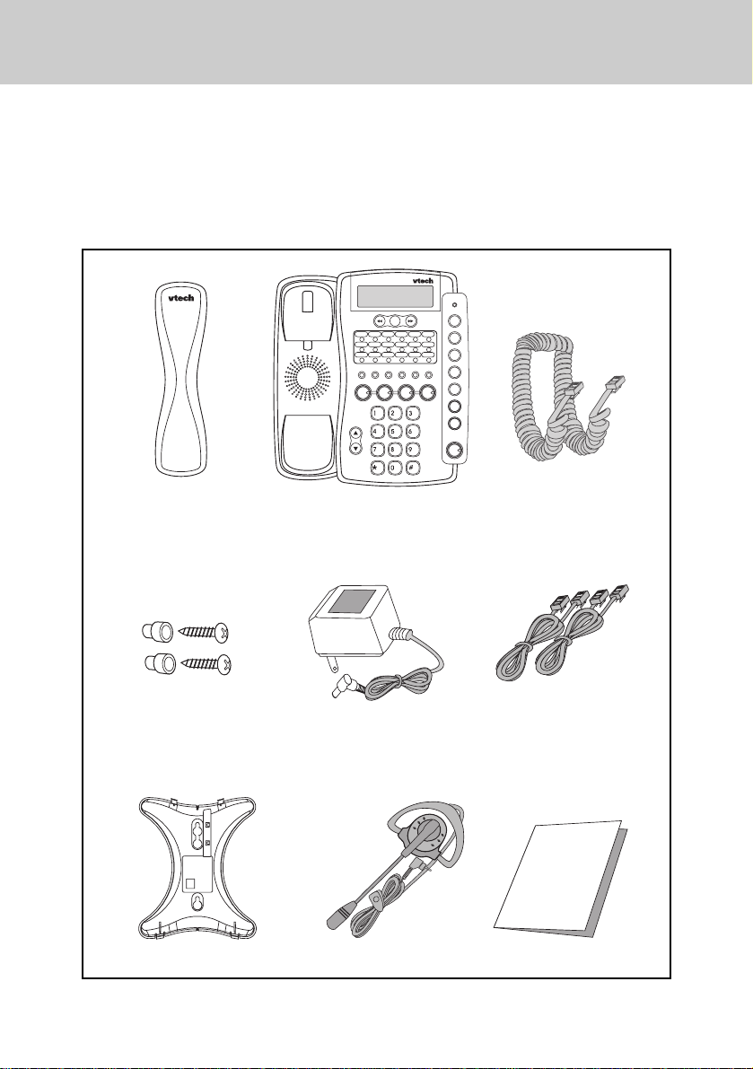
4. Parts Check list
1. Handset
2. B/U
3. 10 foot handset cord
4. Wall mounting screws and anchors
Handset
Base Unit
5. AC power adapter
6. Two long line cords
7. Desk/Wall mount bracket
8. Over the ear headset
9. Manual
10 Foot Handset Cord
Wall Mounting
Screws & Anchors
Desk/Wall Mount Bracket
AC Power Adapter
Over the Ear Headset
5
Two long Line Cords
(for desk mounting)
USER’S MANUAL
VT 4121
Operation Manual
Page 6

FCC REGULATIONS
This equipment complies with Parts 15
and 68 of the Federal Communications
Commission (FCC) rules for the United
States. It also complies with regulations RSS210 and CS-03 of Industry
and Science Canada. Operation is
subject to the following two conditions:
1. This device may not cause interference, and
2. This device must accept any interference, including interference that
may cause undesired operation of
the device.
A label is located on the underside of
the base unit containing either the
FCC registration number and Ringer
Equivalence Number (REN) or the IC
registration number and Load Number.
You must, upon request, provide this
information to your local telephone
company.
This equipment is compatible with
inductively coupled hearing aids.
Should you experience trouble with
this telephone equipment, please contact:
VTECH COMMUNICATIONS
SERVICE DEPT. at 1-800-595-9511.
For repair/warranty information. The
telephone company may ask you to
disconnect this equipment from the
line network until the problem has
been corrected.
FCC Part 15
Warning: Changes or modifications to
this unit not expressly approved by the
party responsible for compliances could
void the user's authority to operate the
equipment.
The equipment has been tested and
found to comply with part 15 of the
FCC rules. These limits are designed
to provide reasonable protection
against harmful interference in a residential installation. This equipment
generates, uses and can radiate radio
frequency energy and, if not installed
and used in accordance with the
instructions, may cause harmful interference to radio communications.
However, there is no guarantee that
interference will not occur in a particular installation. If this equipment does
cause harmful interference to radio or
television reception, which can be
determined by turning the equipment
off and on, the user is encouraged to
try and correct the interference by one
or more of the following measures:
• Reorient or relocate the receiving
antenna.
• Increase the separation between the
equipment and receiver.
• Connect the equipment into an
outlet or on a circuit different from
that to which the receiver is
connected.
• Consult the dealer or an
experienced radio/TV technician for
help.
6
Page 7

FCC REGULATIONS
FCC Part 68
The FCC requires that you connect
your cordless telephone to the nationwide telephone network through a
modular telephone jack (USOC RJ11C,
RJ11W or RJ14).
Your telephone company may discontinue your service if your equipment
causes harm to the telephone network.
They will notify you in advance of
disconnection, if possible. During
notification, you will be informed of
your right to file a complaint with the
FCC.
Occasionally, your telephone company
may make changes in its facilities,
equipment, operation, or procedures
that could affect the operation of your
equipment. If so, you will be given
advance notice of the change to give
you an opportunity to maintain uninterrupted service.
The base unit contains no user serviceable parts. The handset contains
a user replaceable battery pack.
This equipment may not be used on
coin service provided by the phone
company or Party Lines.
The REN is useful in determining the
number of devices you may connect to
your telephone line and still enable the
devices to ring when you receive a call.
The general rule is that the REN value
should not exceed 5.0A total; ho we ver ,
contact your local telephone company
for the specific number in your area.
If it is determined that your telephone
equipment is malfunctioning, the FCC
requires that it not be used and that it
be unplugged from the modular jack
until the problem has been corrected.
Repairs to this telephone equipment
can only be made by the manufacturer
or its authorized agents or by others
who may be authorized by the FCC.
For repair procedures, follow the instructions outlined under the VTECH
Limited Warranty.
7
Page 8

IMPORTANT SAFETY INSTRUCTIONS
When using your telephone equipment, basic safety precautions should
always be followed to reduce the risk
of fire, electric shock and injury to
persons, including the following:
1. Read and understand all
instructions.
2. Follow all warnings and instructions
marked on the product.
3. Unplug this product from the wall
outlet before cleaning. Do not use
liquid cleaners or aerosol cleaners.
Use a damp cloth for cleaning.
4. Do not use this product near water
(for example, near a bath tub,
kitchen sink, or swimming pool).
5. Do not place this product on an
unstable cart, stand, or table. The
product may fall, causing serious
damage to the product.
6. Slots and openings in the cabinet
and the back or bottom are provided
for ventilation. To protect it from
overheating, these openings must
not be blocked by placing the
product on the bed, sofa, rug, or
other similar surface. This product
should never be placed near or
over a radiator or heat register.
This product should not be placed
in a built-in installation where proper
ventilation is not provided.
7. This product should be operated
only from the type of power source
indicated on the marking label. If
you are not sure of the type of
power supply to your home, consult
your dealer or local power company.
8. Do not allow anything to rest on the
power cord. Do not locate this
product where the cord will be
abused by persons walking on it.
9. Never push objects of any kind into
this product through cabinet slots
as they may touch dangerous
voltage points or short out parts
that could result in a risk of fire or
electric shock. Never spill liquid of
any kind on the product.
10.To reduce the risk of electric shock,
do not disassemble this product,
but take it to a VTech authorized
service facility. Opening or
removing cabinet parts other than
specified access doors may expose
you to dangerous voltages or other
risks. Incorrect reassembling can
cause electric shock when the
appliance is subsequently used.
11. Do not overload wall outlets and
extension cords as this can result
in the risk of fire or electric shock.
12. Unplug this product from the wall
outlet and refer servicing to a
VTech authorized service facility
under the following conditions:
a. When the power supply cord or
plug is damaged or frayed.
b. If liquid has been spilled into
the product.
c. If the product has been ex-
posed to rain or water.
8
Page 9

IMPORTANT SAFETY INSTRUCTIONS
d. If the product does not operate
normally by following the operating instructions. Adjust only
those controls that are covered
by the operating instructions,
because improper adjustment
of other controls may result in
damage and will often require
extensive work by a VTech
authorized technician to restore
the product to normal operation.
e . If the product has been dropped
and the cabinet has been damaged.
f. If the product exhibits a distinct
change in performance.
13.Avoid using a telephone (other
than a cordless type) during an
electrical storm. There may be a
remote risk of electric shock from
lighting.
14.Do not use the telephone to repor t
a gas leak in the vicinity of the leak.
SA VE THESE INSTRUCTIONS
9
Page 10
INSTALLATION
1. Site Planning
Select a location where the speakerphone will not interfere with daily activities. You can choose to connect the
speakerphone to as many as four telephone lines. The speakerphone can be
connected to two 2-line (RJ14C) modular telephone jacks to accommodate all
four lines. The speakerphone is factoryprogrammed for intercom extension
number 12.
When the telephone is first installed, the
display will show a message to check
the clock and the extension ID. Refer to
the Programming section to set the extension number.
IMPORT ANT :For all system features
to operate correctly , every speakerphone,
must be connected to
the same Line 2 wiring.
They do not need to be
located in the same
area.
2. Installing the Speakerphone
You can choose from two (2) installation options:
•
Locate the telephone on a desk or
tabletop, or
•
Mount the telephone on the wall.
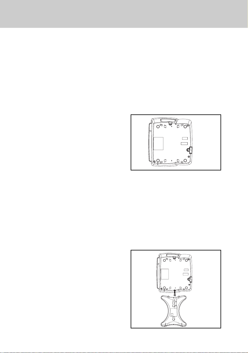
2.1Desk/Tabletop Mounting
T o hav e better viewing angle, y ou could
choose to install the desk/wall mount
bracket by squeezing the side tabs on
the thicker end of the bracket, inser t
them into their respective slots.
a. Position the telephone in the desired
location on a tabletop or desk.
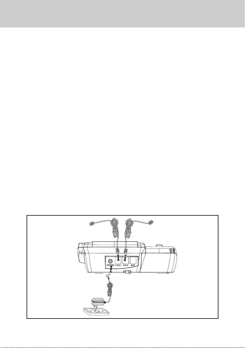
b. Plug one of the long line cords into
the L1/2 jack at the back of the telephone. Plug the other long line cord
into the L3/4 jack.
c. Plug the AC adaptor power cord into
the jack at the back of the telephone.
Note: Use only the AC power adaptor
provided with the telephone.
L1/L2 TELEPHONE JACK L3/L4 TELEPHONE JACK
ELECTRICAL OUTLET
10
Page 11
INSTALLATION
d. Insert one end of the handset cord
into the handset and the other end
into the left side of the telephone.
Place the handset in the telephone
cradle.
e. Plug the two long line cords into the
wall jacks.
Double check that you
have not reversed the L1/L2 and
L3/L4 cord connections.
f. Plug the AC po wer cord adaptor into
a standard 120V AC wall outlet. The
display shows “Check Clock & ID “.
Refer to the programming section to
program the clock and change the
extension ID.
g. Ensure that all cords are positioned
to prevent tripping and rubbing
which could create a potential electrical hazard.
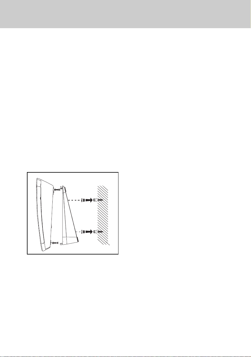
2.2 Wall Mounting
You will want to ensure the following:
• The location where the telephone
will be mounted should be away
from electrical cables, pipes, or
other items which may be punctured
when the screws are inserted into
the wall.
• The wall surface should be capable
of supporting the telephone weight.
the wall.
1. Insert the two (2) screws and anchoring devices into the wall 3-5/8
inches apart vertically, allowing
approximately 3/16 inch between
the wall and screw heads for mounting the telephone. Ensure that the
screws are secure.
2. T urn the speakerphone over to view
the bottom.
3. If you have already installed the
desk/wall mount bracket in desk
mode, please remove the desk/ w all
mount bracket b y gently moving one
tab at a time while pulling the peg
out of the tab hole.
4. Rotate the bracket and install it in
the wall mounting position by aligning the four holes on the brack et with
the four hooks on the bottom of the
telephone.
• Use the screws and anchoring devices provided with the telephone.
• The telephone is located near an
AC outlet.
Two (2) long line cords are provide to
meet various wall mounting conditions.
A template is provided at the back of
this manual to assist you with the installation of the telephone directly onto
11
Page 12
INSTALLATION
5. Slide the bracket down onto the
hooks and snap into place.
6. Plug one of the line cord into the L1/
L2 jack at the back of the telephone.
Plug the other line cord into the L3/
L4 jack.
7. Plug the AC adapter power cord into
the bottom of the telephone. Use
only the AC power adapter provided
with the telephone.
8. Position the telephone on the two
screws in the wall and slide the telephone downward to secure it to the
wall.
9. Rotate the handset tab by lifting up
and turning to position it in the wall
mount mode.
10.Inser t one end of the handset cord
into the handset and the other end
into the left side of the telephone.
Hang the handset in the telephone
cradle.
11.Plug the two line cords into the wall
Double check that you have
jacks.
not reversed the L1/L2 and L3/L4
cord connections.
12.Plug the AC power cord adapter into
a standard 120V AC wall outlet. The
display shows “ Check Clock & ID”.
Refer to the programming section to
program the clock and change the
extension ID.
13.Ensure that all cords are positioned
to prevent tripping and rubbing
which could create a potential electrical hazard.
12
Page 13
PROGRAMMING
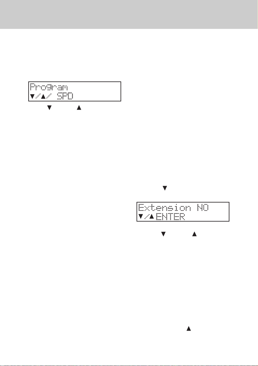
1. General Programming Guidelines
• Press PROGRAM to enter the programming mode. The MUTE (EN-
TER) will light steady. The display
will show:
• The VOLUME buttons are used
for scrolling through the programming selections.
• The MUTE (ENTER) button acts as
“enter”.
• Press HOLD to return to the previous main menu.
• Pressing a SPEED DIAL button allows you to program that particular
button.
• Press ERASE to erase a pre viously
programmed setting.
Note 3: If you are already in the pro-
gramming mode all the features can be programmed
consecutively without pressing PROGRAM again.
2. Extension Number
Default setting: 12
Extension Number Range: 11-22
Each Speakerphone must have a
unique extension number programmed. It is highly recommended
that you assign a new extension
number at the time of installation.
You will hear a continuous alerting tone
if two speakerphones are assigned the
same extension number.
1. Press PROGRAM.
2. Press
shows:
VOLUME. The display
• Press END to exit the programming
mode.
Note1: A button must be pressed
within about 30 seconds or the
programming mode will be automatically cancelled.
Note 2: When a feature has been suc-
cessfully programmed, you
will hear a single confirmation
tone and the display will show
“OK!”. If the feature has not
been programmed correctly,
you will hear a double tone
and the display will show
“Fail!”.
3. Press MUTE (ENTER).
4. Press
tension number.
5. Press MUTE (ENTER) to save.
3. Tone/Pulse Dialing
Default Setting: Tone
If you have tone dialing service from
your telephone company, you will want
to ensure that your telephone is set for
tone dialing mode.
1. Press PROGRAM.
2. Press V OLUME
shows:
13
VOLUME to select ex-
until the display
Page 14

PROGRAMMING
3. Press MUTE (ENTER). The display
shows:
4. Press VOLUME to select the
dialing mode.
5. Press MUTE (ENTER) to save.
4. Date and Time
Default setting: Jan 01 FR 1:00A
You can program the time in either 12-
hour or 24-hour (military) format.
1. Press PROGRAM.
2. Press VOLUME
shows:
until the display
9. Press MUTE (ENTER) to select the
appropriate day and proceed to programming the clock for AM/PM or
24-Hour.
10. Press
tween the three choices.
11.Press MUTE (ENTER) to select the
appropriate setting and proceed to
programming the hour.
12.Press
choice for the hour.
13.Press MUTE (ENTER) to select the
appropriate hour and proceed to
programming the minutes.
14.Press
choice for the minutes.
15.Press MUTE (ENTER) to select the
appropriate minutes. You will hear a
single confirmation tone and the display will show the new date and
time.
5. CO/PBX Line Ringing
Default Setting: Enabled
VOLUME to switch be-
VOLUME to view the
VOLUME to view the
3. Press MUTE (ENTER) to program
the month.
4. Press
months.
5. Press MUTE (ENTER) to select the
appropriate month and proceed to
programming the date.
6. Press
choice for the date.
7. Press MUTE (ENTER) to select the
appropriate date and proceed to
programming the day of the week.
8. Press
choices for the day.
VOLUME to view the
VOLUME to view the
VOLUME to view the
You can program the ringer for each
central office/PBX line(1-4). If y ou do not
want the line(s) to ring at your telephone, choose the “OFF” setting for
each line.
1. Press PROGRAM.
2. Press
shows:
3. Press MUTE (ENTER) .The displa y
shows:
14
VOLUME until the display
Page 15

PROGRAMMING
4. Press MUTE (ENTER) again. The
display shows:
5. Press VOLUME to choose the
setting.
6. Press MUTE (ENTER).
To continue programming the remaining lines press VOLUME
perform steps 4-6.
6. CO Line Ring Tone
Default Setting: 1
Range: 1-4
You can choose one of four different
ringing tones for your telephone. The
selection chosen will apply to all four
CO lines on your telephone.
1. Press PROGRAM.
2. Press
shows:
VOLUME until the display
and then
Range: Disable, 2 seconds to 30 seconds (2 second increments)
You may choose to have the CO line
ringing delayed for overflow and caller
ID applications.
1. Press PROGRAM.
2. Press
shows:
3. Press MUTE (ENTER). The displa y
shows:
4. Press V OLUME to select the
delay time between 2 seconds and
30 seconds (in 2 second increments).
5. Press MUTE (ENTER).
8.
CO T runk Connection
VOLUME until the display
3. Press MUTE (ENTER). The displa y
shows:
4. Press VOLUME to select a dif-
ferent ring tone. You will hear a
sample tone for each choice.
5. Press MUTE (ENTER).
7. Delayed Ringing
Default Setting: Disabled
Default Setting: All Lines Connected
Y our telephone can detect another tele-
phone, facsimile, or modem that is inuse on one or more of the CO lines. This
privacy feature will prevent accidental
instruction by another VT4121 speakerphone user. The “Line-In-Use” circuit
will light the CO line button if the line is
not physically connected. F or instance,
if you only have lines 1,2, and 3 connected you can disable line 4( if you do
not disable that line, the lamp will remain lit steady even though you can’t
access the line). When you disable a
CO line the lamp and button will not operate.
15
Page 16

PROGRAMMING
1. Press PROGRAM.
2. Press
shows:
3. Press MUTE (ENTER),The display
shows:
4. Press MUTE (ENTER). The display
shows:
5. Press VOLUME to choose the
setting.
6. Press MUTE (ENTER) to save.
To continue programming the remaining lines press VOLUME
perform steps 4-6.
9. Automatic Line Selection
Default Setting: CO 1
VOLUME until the display
and then
shows:
4. Press VOLUME to choose the
line( or intercom) you want to program for this feature.
5. Press MUTE (ENTER) to save.
10.Call Forward
Default Setting: OFF
Range 11-22
When this feature is enabled (on) any
intercom or transferred call you receiv e
will be forwarded to the Speakerphone
extension that you have identified.
When the feature is enabled, upon receiving a call you will hear a triple tone
and the display will briefly show Call
forward on the display prior to the call
being forwarded.
1. Press PROGRAM.
2. Press
shows:
VOLUME until the display
The line that you assign for automatic
line selection( line preference) will be
automatically accessed when you pick
up the handset or press SPEAKER.
1. Press PROGRAM.
2. Press VOLUME until the display
shows:
3. Press MUTE (ENTER). The display
3. Press MUTE (ENTER). The display
shows:
4. Press VOLUME to select the
extension number (11-22) where
you want to forward your calls.
5. Press MUTE (ENTER) to save.
16
Page 17

PROGRAMMING
11. Auto Mute Enable/Disable
Default Setting: Disable
This feature prevents unauthorized
eavesdropping when someone makes
a single page to you.
Note: For intercom page with
handsfree reply at your extension, Auto Mute must be set to
Disable.
1. Press PROGRAM.
2. Press VOLUME
shows:
3. Press MUTE (ENTER) . The display
shows:
4. Press VOLUME to choose be-
tween the enable or disable setting.
5. Press MUTE (ENTER).
12. Flash
Default Setting: 0.7 seconds
Range: 0.1 seconds to 1.2 seconds
This feature is typically used to access
custom calling service. You may also
use Flash to end a call without hanging
up the handset or pressing SPEAKER.
until the display
3. Press MUTE (ENTER). The display
shows:
4. Press V OLUME to choose the
flash length.
5. Press MUTE (ENTER) to save.
13. Speed Dial
You can store eighteen (18) frequently
dialed numbers in a speed dial bin by
pressing the appropriate speed dial
button during programming.
A number stored in the Called ID
memory can be stored in a speed dial
bin. You can store numbers in either
pulse or tone dialing modes. Pauses
and flashes may also be stored in
memory. Each speed dial bin can store
up to 16 digits (numbers) including
pause, tone, and flash.
13.1 Storing a T elephone Number in
Speed Dial
1. Press PROGRAM.
2. Press SPEED DIAL Button 1. The
display shows:
1. Press PROGRAM.
2. Press VOLUME
shows:
until the display
3. Press MUTE (ENTER). The display
shows:
17
Page 18

PROGRAMMING
4. Dial the number (digi) you want to
store.
5. Press MUTE (ENTER) to save.
Repeat step 2 and press another speed
dial button to continue programming
speed dial numbers.
13.2 Storing a Caller ID Number
ing to the line-in-use. This feature may
not be compatible with some telephone
systems. You may disable line-in-use
detection if you use the speakerphone
as a private telephone system extension.
1. Press PROGRAM.
2. Press
shows:
VOLUME until the display
1. Display the number in the caller ID
list. (Refer to Caller ID Operation).
2. Press PROGRAM.
3. Press the SPEED DIAL button.
4. Press MUTE (ENTER).
5. Press CID.
6. Press MUTE (ENTER) to save.
13.3 Erasing the Contents of a
Speed Dial Bin
1. Press PROGRAM.
2. Press the SPEED DIAL button.
3. Press MUTE (ENTER) .
4. Press ERASE twice. For example,
if you are deleting the contents of
bin 10, the display will show:
14.Line In Use Detection
Default Setting: Enable
This feature allows the speakerphone
to detect other telephone devices using any of the four telephone lines. The
speakerphone indicates line-in-use status by illuminating the LED correspond-
3. Press MUTE (ENTER) . The display
shows:
4. Press VOLUME to choose setting.
5. Press MUTE (ENTER) .
15.Reset default Values
Y ou ma y clear all the programmed data,
and reset all parameters back to the
original factory default values.
1. Press PROGRAM.
2. Press
shows:
3. Press MUTE (ENTER) . The display
shows:
VOLUME until the display
18
Page 19

PROGRAMMING
For your reference, here is the default value list:
Extension ID: 12
Call forward: Disable
Ringer On/Off: “on” for each co line
Ringer Type: Type 1
Delayed Ring: Disable
Co Trunk Connection: Connected for each line
Line Preference: CO #1
Auto-Mute: Disable
Tone/Pulse dialing: Tone Dialing
Flash Length: 700 mili-seconds
LIU Detection: Enable
Calendar: Jan 01 FR 12:00A
Area Code Setting: None
Speed Dialing: Empty
Ringer V olume: Middle
Speaker Volume: Level 4
Handset Volume: Minimum Level
Headset Volume: Middle
19
Page 20

BASIC OPERATION
1. Lamp (LED) Operation
Line Buttons
Off
• Lamp is off when the line is not being used.
On steady
• Lamp is on if the line is being used
by another extension.
Wink
• Lamp will “wink” to indicate the line
you are talking on.
Slow flash
• Lamp flashes slowly when an incoming call is ringing or you receive
a transferred call.
Fast flash
• Lamp flashes fast when another
extension places that line on hold.
Very fast flash
• Lamp flashes very fast when you
place a line on hold or you transfer
a call.
ICM Button
Off
• Lamp is off when you are not using
the intercom.
On steady
• Lamp is on steady when the intercom path is busy.
Wink
• Lamp will “wink” when you are using the intercom.
Fast flash
• Lamp flashes fast when an intercom
call is ringing at your phone.
Speaker Button
Off
• Lamp is off when the telephone is
idle or you are using the handset.
On steady
• Lamp is on if you are using the
speakerphone.
Slow flash
• Lamp slowly flashes when you are
using Auto Busy Redial (while waiting for the telephone to redial.)
Fast flash
• Lamp flashes fast when the Auto
Busy Redial feature is used.
Wink
• Lamp will “ wink” when you are using the headset.
Mute (Enter) Button
Off
• Lamp is off when the telephone is
not muted.
On steady
• Lamp is on when the telephone is
muted, the telephone is in the programming mode or the telephone is
performing Auto Busy Redial.
Message Lamp
The lamp to the right of the CID keys
will:
20
Page 21

BASIC OPERATION
Slow Flash
• Lamp will slowly flash when you
have new Telco voice messages
(subscription required.)
Fast Flash
• Lamp will flash quickly when the
speakerphone is ringing.
On steady
• Lamp will light steady when the
speakerphone is in the Do Not Disturb mode.
Off
• Lamp is off if there are no new messages and the Do Not Disturb mode
is off.
2. Line-In-Use Indication
If a single line telephone or other equipment such as a facsimile machine is
using a line, that line lamp will light on
your telephone to indicate that the line
is busy. You may intrude on that busy
line to verify that the line is not out of
order. Howev er , lines being used solely
by VT 4121 speakerphone are privacy
protected form intrusion.
4. Adjusting the Speaker Volume
Level
While using the speakerphone, you may
adjust the volume level of the distant
party’s voice by pressing
. You will hear a confirmation tone
when the highest or lowest volume setting is reached.
5. Adjusting the Headset Volume
Level
While using a headset, you may adjust
the volume level of the distant party’s
voice by pressing VOLUME . You
will hear a confirmation tone when the
highest or lowest volume setting is
reached.
6. Adjusting the Ringer Volume
Level
While the telephone is idle (not being
used), you may adjust the ringer vol-
ume level by pressing
You will hear a confirmation tone when
the highest or lowest volume setting is
reached.
VOLUME
VOLUME .
3. Adjusting the Handset Volume
Level
While using the handset, you may adjust the volume level of the distant
party’s voice by pressing
. You will hear a confirmation tone
when the highest or lowest volume setting is reached.
VOLUME
7. AC Power Failure Indication
If power has been interrupted to your
speakerphone the display will show:
Press any button or key to cancel the
power failure message.
21
Page 22

BASIC OPERATION
8. Making an Outside Call
Each VT 4121 speakerphone may ha ve
four (4) outside lines programmed for
direct access and dialing.
8.1Using the Handset
1. Lift the handset. (If you have Automatic Line Selection enabled, the
telephone will automatically select
a line-proceed to Step 3 ).
2. Press a line button.
3. Dial the telephone number. The display will show the digits you dial.
After the last digit is dialed, the timer
will soon begin to display the call
duration:
Note: If you dial more than 15 digits,
all the digits will shift to the left
of the display:
4. Hang up the handset or press END
when you’ve completed your call.
8.2Using the Speakerphone / Head-
set
Note: The Speakerphone will auto-
matically switch to headset
mode when a compatible headset is plugged into the headset
jack.
3. Dial the telephone number. The display will show the digits you dial.
After the last digit is dialed, the timer
will soon begin to display the call
duration:
Note: If you dial more than 15 digits,
all the digits will shift to the left
of the display.
4. Press SPEAKER or END when
you’ve completed your call.
9. Answering an Outside Call
9.1 Using the Handset
Lift the handset. The ringing outside line
is automatically selected.
9.2 Using the Speakerphone
1. Press the flashing line button,
OR
Press SPEAKER
Note: When several lines are ringing,
you can directly answ er any line
by pressing the associated line
button.
10.Placing a Call on Hold
While on a call:
1. Press SPEAKER. (If you have Au-
tomatic Line Selection enabled, the
telephone will automatically select
a line-proceed to Step 3.)
2. Press a line button.
1. Press HOLD. The displa y will briefly
show:
22
Page 23

BASIC OPERATION
2. Hang up.
Press ICM. If you want to make an
intercom call without
autotransferring the line or simply
hang up the handset and the line
will remain on hold.
11. Retrieving a Call on Hold
When you place a call on Hold at your
speakerphone you will hear a brief remainder tone after 30 seconds.
To retrieve a held call press the line
button corresponding to the holding line.
12.Making an Intercom Call
12.1 Using the Handset
Note: Skip Step 1 if you programmed
the intercom for Automatic Line
Selection.
1. Press ICM. The display will show:
2. Lift the handset.
3. Dial the desired intercom number
(from 11 to 22). For instance, if you
dial intercom number 15 the display
will show:
Note1: If the telephone you are call-
ing is busy, you will hear busy
tone. If the telephone you are
calling is in Do Not Disturb
(DND) mode, you will hear
DND tone.
Note 2: If you do not perform Step 3
above within approximately 10
seconds, the intercom will be
released.
12.2 Using the Speakerphone
Note: Skip Step 1 below if you pro-
grammed the intercom for A utomatic Line Selection.
1. Press ICM. The display will show:
2. Press SPEAKER.
3. Dial the desired intercom number
(from 11 to 22). For instance, if you
dial intercom number 15 the display will show:
When the person you called answers,
your display will show:
When the person you called answers,
your display will show:
4. Hang up the handset to end the call.
4. Press SPEAKER to hang up.
Note 1: If the telephone you are call-
ing is busy, you will hear busy
tone. If the telephone you are
calling is in Do Not Disturb
23
Page 24

BASIC OPERATION
(DND) mode, you will hear
DND tone.
Note 2: If you do not perform Step 3
above within approximately 10
seconds, the intercom will be
released.
12.3 Using the Direct Station Buttons
The speed dial buttons are also
preprogrammed for use as Direct Station Selection (DSS) buttons. You can
access extensions 11 through 22 by
simply pressing the appropriate button.
Note: Skip Step 1 below if you pro-
grammed the intercom for A utomatic Line Selection.
1. Press ICM.
2. Lift the handset or press SPEAKER.
3. Press the desired DSS button.
4. Hang up the handset to end the call.
Note1: If the telephone you are call-
ing is busy, you will hear busy
tone. If the telephone you are
calling is in Do Not Disturb
(DND) mode, you will hear
DND tone.
1. Lift the handset.
2. Hang up the handset to end the call.
The display will return to the idle
mode.
13.2 Using the Speakerphone/Head-
set
For example, if Station 12 is calling y ou,
your handset will ring, your ICM button
will flash, and the display will
show:
1. Press ICM or SPEAKER.
2. Press END or SPEAKER to end the
call. The display will return to the idle
mode.
Note 2: If you do not perform Step 3
above within approximately 10
seconds, the intercom will be
released.
13.Answering an Intercom Call
13.1 Using the Handset
For example, if Station 12 is calling y ou,
your handset will ring, your ICM button
will flash, and the display will show:
14. Intercom Call Pick Up
You may answer an intercom call ringing at another speakerphone in the system by pressing ICM.
15. Transferring a Call
While on a line:
1. Press HOLD. The display shows:
24
Page 25

BASIC OPERATION
2. Dial the extension number where
you will transfer the call (or press a
DSS button ). For instance, if you
want to transfer a call to extension
15 the display will show:
Note 1: You will hear a single tone if
the call has transferred.
Note 2: You will hear a transfer re-
minder tone every 30 seconds
if the transfer isn’t answered.
Note 3: Y ou can still transf er calls ev en
if the system intercom is busy.
16. Receiving a Transferred Call
18. Conferencing
A three-way conference call may consist of two (2) outside lines or one (1)
outside line and two (2) extensions.
18.1 Two (2) Outside Lines
While on a call on the first line:
1. Press HOLD. The first line is placed
on HOLD and the display shows:
2. Press a second line button.
3. Dial the telephone number for the
second party.
4. Press CONFERENCE. The display
will show the second telephone
number that you dialed:
Any extension ma y pick-up a transferred
call.
You will hear transfer ring tone and the
lamp for the transferred line will flash.
17. Muting a Call
The Mute feature turns off the telephone
handset and speakerphone microphone so the distant party cannot hear
you. Y ou can also use Mute to bloc k out
background noise momentarily.
While on a line or using the intercom:
1. Press MUTE (ENTER). The lamp
will light.
2. Press MUTE (ENTER) again to deactivate the feature.
5. Hang up to disconnect the lines and
end the conference.
18.2 One (1) Outside Line and Two
(2) Extensions
While on a call on the first line:
1. Press HOLD. The first line is placed
on Hold and the display shows:
2. Press ICM.
3. Dial the intercom number for the
other internal par ty. For example, if
you dial extension 20 the display will
show the following when extension
25
Page 26

BASIC OPERATION
20 answers:
4. Press CONFERENCE. The display
shows:
5. Hang up to end the conference.
Note: When y ou hang up extension 20
will still be connected to the line
until that extension hangs up.
19. Paging
19.1 Paging Another Speakerphone
1. Lift the handset.
2. Press PAGE. The display shows:
3. Dial the desired intercom number.
For instance, if you dial extension
15 the display shows:
Note: If you have programmed Auto-
Mute, the Mute lamp will turn on
and sounds in your room will not
be heard by the calling party.
1. Lift the handset or press MUTE (EN-
TER) (if the Mute lamp is lit).
2. Hang up to end the call.
19.3 Changing Signaling Modes
If you have made a voice page to an
extension and do not receive a reply,
press ICM and the other extension will
begin tone signaling to alert users in
the area.
To Switch From Page Mode to Tone
Ringing:
After establishing a voice page to another extension, press ICM.
To Switch From Tone Ringing to Page
Mode:
After establishing an intercom call,
Press PA GE.
19.4 To Voice Page All Speaker-
phone Extensions
4. Make your page announcement.
Note: Only VT4121 speakerphones
can receive voice paging.
19.2 Answering a Page
You will hear a tone prior to receiving a
voice page. You may then answer the
page using the speakerphone.
1. Lift the handset.
2. Press PAGE ALL. The display
shows:
3. Announce your message.
26
Page 27

BASIC OPERATION
19.5 Receiving a Voice Page to All
Speakerphone Extension.
For example, if extension 12 sends a
V oice Page to all telephones in the system, the extension telephone will show:
19.6 Meet Me Answer to All Page
Press PAGE or PAGE ALL to answer
the page. For instance, if extension 12
performs an All Page, the display
shows:
20. Do Not Disturb
You may use the DND feature to a v oid
telephone interruptions. When activated, you will not hear incoming ringing from outside lines, intercom calls
and pages.
While the telephone is idle:
Press DND. The display shows:
Note: Press DND again to deactivate
DND. The display will return to
the idle mode.
21. Using the Flash Button
You may use Flash instead of pressing
the hookswitch to access custom calling features provided by y our telephone
service such as call waiting, 3-way calling, etc.
While on a line:
1. Press FLASH to obtain new dial
tone.
2. Dial the new telephone number or
service code.
22. Using the Pause Feature
During speed dialing you can use the
Pause feature to insert a delay in a dialing sequence. P ause ma y be needed
to access certain banking and long distance services. Each pause is 3 seconds. During manual dialing, you can
press the button repeatedly to create a
longer delay.
While on a line:
1. Dial the numbers prior to the pause.
2. Press REDIAL/PA USE.
3. Dial the remaining number after the
pause.
23. Auto Busy Redial
T o continue dialing a b usy number from
the telephone:
When you dial a telephone number that
is busy, hang up and perform the following steps.
1. Press SPEAKER (If you have Automatic Line Selection enabled, telephone will automatically select a
line-proceed to Step 3.)
2. Press a line button.
3. Press REDIAL/PAUSE. The tele-
phone will dial the number. If the
distant party is still busy, the telephone will hang up after about 15
seconds, it will then wait about 5
27
Page 28

BASIC OPERATION
seconds, and then dial the number
again.
4. When you hear ringing, lift the handset to speak.
Note: The MUTE lamp lights steady
when the Auto Busy Redial feature is activated. The SPEAKER
lamp will flash slowly during dialing attempts, and quickly during dialing.
24. Last Number Redial
To dial the last number dialed from the
telephone:
1. Lift the handset.
2. Press a line button.
3. Press REDIAL/PAUSE and the
number is dialed automatically.
Note: You m ay also redial using the
speakerphone by simply pressing REDIAL/PAUSE. If you
press SPEAKER first, you will
activate Auto Busy Redial.
25. Speed Dialing
1. Lift the handset.
2. Press a SPEED DIAL button. The
number will be dialed automatically.
Privacy feature allows someone else to
join your conv ersation on the same line.
To override (disable) Call Privacy:
Press the line button that you are cur-
rently accessing until you hear a single
tone.
To enable Call Privacy:
Press the line button until you hear a
double tone.
Note 1: When non-system equipment,
such as a single line telephone
or facsimile machine, is using
a line, any VT 1421 system
telephone may access that line
also. However, when a system
telephone accesses the line
the Call Privacy feature is enabled and additional system
telephone may not access the
line.
Note 2: Due to the direct wiring of
single line telephones,
cordless telephones, facsimile
machines, or modems, it is not
possible to prevent these devices from accidentally intruding on a line that you are using.
Note: You may use the speakerphone
to dial a speed dial number by
simply pressing the SPEED
DIAL button.
26. Call Privacy
Another extension cannot access a line
that you are using unless you override
Privacy for that call. Ov erriding the Call
27. Pulse-to-Tone Switching
If you are pulse dialing service you may
need to access a computer or calling
services that use tone dialing.
While on a line:
1. Dial the telephone number in pulse
mode.
2. Dial *tone to change to the tone dialing mode.
28
Page 29

BASIC OPERATION
3. Dial the remaining numbers to be
dialed in the tone mode.
Note: When you hang up the tele-
phone will return to the pulse
dialing mode.
28. Message Waiting Light
If you subscribe to voice mail service
from your local telephone company , the
LED to the right of the Caller ID keys
will flash when someone has left a message for you. This f eature is compatib le
with FSK signaling from the telephone
company*. The display will indicate line
(1-4) that the message signal was received. The display will show:
In this example, there is a message
waiting on L1 and L4. F ollow y our voice
mail service instructions for retrieving
a message.
Note: Your telephone company may
send a signal to remove the indicator light once you have retrieved your messages, or you
may press ERASE twice to remove the indicator light manually.
*Not all local telephone service
providers send the FSK signal
required to activate the Message Waiting Light. If you have
voice messaging, but your Message Waiting does not flash
when receive new messages,
check with your service, provider to see if FSK signaling is
available.
29
Page 30

CALLER ID OPERATION
IMPORTANT: You must subscribe to
Caller ID service provided by your local
telephone company
on each line you wish
to receive call information.
1. Caller ID Buttons
There are five (5) buttons used to access Caller ID functions:
CID
• T o switch betw een multiple caller ID
screens during 2 or more ringing
calls.
• T o mov e backward through the caller
ID list.
• To move forward through the caller
ID list.
2.1To Program the Area Code
1. Press PROGRAM.
2. Press VOLUME
shows:
3. Press MUTE (ENTER).
4. Dial the area code.
5. Press MUTE (ENTER).
2.2 To Erase the Programmed Area
Code
1. Press PROGRAM.
2. Press VOLUME
shows:
3. Press MUTE (ENTER).
4. Press ERASE. The display will
show:
until the display
until the display
ERASE
• T o er ase a call from the caller ID list.
DIAL
• To dial a number from the caller ID
list.
2. Programming the Area Code
Default: empty
When you receive a local call from a
person with your same home area code,
the telephone will not store the area
code. This feature will enable you to
redial the caller in the future.
5. Press ERASE again. The area code
is deleted.
3. Receiving a Call
You will need to subscribe to the Caller
ID service from your telephone company to receiver Caller ID information.
When a call is received, the display will
show the name and number of the
caller, and the date and time the call is
received. Some telephone companies
send both the name and number of the
30
Page 31

CALLER ID OPERATION
caller. Other telephone companies may
only provide the number of the calling
party.
Note 1: When the VT 4121 is con-
nected behind a PBX or key
system, the caller ID features
cannot be used.
3.1 Receiving a Name and Number
Call
The display will show the caller ID information typically after the first ring:
Where: L1 is the ringing line number
1235215 is the number of the
caller
ABC CO. is the name of the
caller
Note: The display will return to the
idle mode when:
• The caller hangs up and ringing
stops.
• An extension telephone answers the call.
• You answer the call and hang
up.
• You perform another telephone
function.
caller ID information for subsequent
ringing lines. Once you have received
the information for all the ringing lines,
press CID again and the displa y will return to the date and time mode.
The display will first show the caller ID
information for Line 1:
1. Press CID to revie w the inf ormation
for Line 2:
2. Press CID to return to the time/date
display if no other lines are ringing.
3. Press CID to revie w the information
for Line 1 again:
3.3Receiving a Number Only Call
The display will show:
3.4Receiving a Blocked Call
3.2 Receiving Multiple Calls
If two or more lines are ringing, the telephone will show the caller ID information for the line that began ringing first.
Press CID to view the caller ID information for the next ringing line. You can
continue to press the button to view
Sometimes a caller will prevent their
number from being displayed on your
telephone:
31
Page 32

CALLER ID OPERATION
3.5Receiving a Call from Outside the
Calling Area
If a caller is outside of your Caller ID
area:
Where:
RR -Index no. of the call
4. Reviewing Calls in the Caller List
Information for a maximum of ninetynine (99) calls will be maintained. If
more than 99 calls are received, the
newest call will replace the oldest call
in the list.
1. Press or . The display will
show the total Caller ID record number and new call number.
L -T elephone line num-
(NUMBER) -Phone number
(NAME) -Caller’s name
(DATE & TIME) -Date and time call
NEW -NEW call record or
EXAMPLE:
list (01-99)
ber associated with
call (1-4)
record was received
not (no label)
2a.Press to display the information
of the first call record.
2b. Press to display the information
of the last call record.
3a. Press to display the information
of the second call record.
3b. Press to display the information
of the first call record again.
4a. Press to repeatedly to scroll
through the list forward.
4b. Press to repeatedly to scroll
through the list backwards.
Note: The call records will be dis-
played in the following format:
Press # to view date and time display:
5. Press END to exit the review mode
and return to the time/date display.
5. Delete an Individual Record from
the List
You can delete individual call records
from the list by pressing ERASE while
reviewing a record in the list.
32
Page 33

CALLER ID OPERATION
6. Delete the Entire Caller ID List
You can delete the entire Caller ID List
by pressing ERASE while viewing the
total calls/new calls display.
7. Dialing a number form the Caller
ID List
You can dial a number from the Caller
ID list while in the review mode.
1. Select a Line Key (L1-L4);
2. Dial any required prefix (1);
3. Press DIAL;
4. The display shows the number digit
by digit as it is dialed.
8. Saving a Number to a Speed Dial
Key
Y ou ma y sav e a number form the Caller
ID List to a Speed Dial Key while in review mode:
1. Enter the programming mode by
pressing PROGRAM. The display
shows:
2. Select an available Speed Dial Key
3. Press MUTE (ENTER) to store the
Caller ID Number on the Speed Dial
Key .
4. Press CID to review calls in caller
ID memory.
5. Press MUTE (ENTER) to confirm
the storing.
33
Page 34

AUX DATA PORT
The Speakerphone is equipped with an auxiliary data por t on the back panel as
shown:
Auxiliary Data Port
The auxiliary data por t can be used to connect any standard single line device to
line 4 for basic line service. This is particularly useful for notebook PC modem connections, as well as fax machines or other single line telephone devices.
34
Page 35

MAINTENANCE
TAKING CARE OF YOUR TELEPHONE.
Your VT4121 contains sophisticated electronic parts, so it must be treated with care.
Avoid rough treatment
Place the handset down gently. Save the original packing materials to protect your
telephone if you ever need to ship it.
Avoid water
Your telephone can be damaged if it gets wet. Do not handle your speakerphone
with wet hands. Do not install it near a sink, bathtub or shower.
Electrical storms
Electrical storms can sometimes cause power surges harmful to electronic
equipment.
For your own safety, use caution when using electric appliances during storms.
35
Page 36

WARRANTY STATEMENT
WHAT DOES OUR WARRANTY COVER?
• Any defect in material or workmanship.
FOR HOW LONG AFTER THE ORIGINAL PURCHASE?
• To the original purchaser only - ONE YEAR.
WHAT WILL VTECH DO?
• At our option, repair or replace your unit.
HOW DO I SEND MY UNIT, IN OR OUT OF WARRANTY?
• In the U.S. Call VTECH Communications customer service for Return
Authorization at: 1-800-595-9511
• Properly pack your unit. lnclude any cables & accessories which were originally
provided with the product. We recommend using the original carton and
packing materials.
• Include in the package a copy of the sales receipt or other evidence of date
of original purchase (if the unit was purchased within the lase twelve months).
• Print your name and address, along with a description of the defect, and
include this in the package Or Vtech Electronics.
• Includ payment for any service or repair not cov ered b y w arr anty, as determined
by VTECH Communications.
• Ship the unit via UPS Insured, or equivalent to:
• In the U.S.
VTECH COMMUNICATIONS
11035 SW 11th Street
Bldg. B Suite 270
Beaverton, OR 97005
VTECH Communications assumes no responsibility for units
sent without prior Return Authorizatlon
36
.
Page 37

TECHNICAL SPECFICATIONS
VT 4121 Speakerphone
Physical: Modular, Desk/
Wall Mounted,
High/Low Angle
Stand
Power: Class 2 Trans-
former
Input: 120VAC, 60Hz,
7W
Output: 12VDC, 400MA
(milliamps)
Electrical: 4 CO/PBX Lines,
2 Wire, Loop Start,
600 Ohms, 24/
48VDC
Ringer Equivalence: 0.3B
Mechanical: 2 Each RJ-14C
Jacks
Line 4 Auxiliary
Jack
2.5mm Headset
Jack
Function Buttons: , CID, ,End,
ERASE, Do Not Disturb, Dial, Page,
Page All, CO Lines 1/
2/3/4*, Intercom*,
Mute(Enter)*, Program, Volume, Conference, Flash,
Redial(Pause),
Speaker*, Hold, 18
Speed Dial Buttons
(*) denotes button
with LED
Dial Keys: 12 Keys, Continuous
DTMF
Dimensions: 237 mm long
212 mm wide
93.5 mm high
Weight: 35.1 ounces (0.994
kg)
Specifications, features, and availability of optional accessories are all sub-
ject to change without prior notice.
Power Jack 12
VDC
LCD: Wide Angle Su-
per-Twist (STN) 2
x16 Alpha-Nu-
meric
37
Page 38

VT 4121
4-Line Speakerphone
Wa
ll Mounting
Template
Use this template when wall
mounting your base unit. To mark
the positions of the mounting
screws, hold this template against
the wall, and press a pencil or pen
point through the center of each
crossmark.
NOTE:
Select a spot where you can screw
into a wooden stud within the wall.
The mounting screws will not hold
securely in plaster or wallboard
alone.
38
Page 39

TABLE OF CONTENTS
INTRODUCTION.................................................................................................. 1
Becoming familiar with your speakerphone......................................................... 1
The display ........................................................................................................... 2
The Features........................................................................................................ 2
Parts Check list .................................................................................................... 5
FCC REGULATIONS ........................................................................................... 6
IMPORTANT SAFETY INSTRUCTIONS ............................................................. 8
INSTALLATION ....................................................................................................10
Site Planning.........................................................................................................10
Installing the Speakerphone .................................................................................10
Desk/Tabletop Mounting................................................................................. 10
Wall Mounting ................................................................................................. 11
PROGRAMMING ................................................................................................. 13
General Programming Guidelines ....................................................................... 13
Extension Number ............................................................................................... 13
Tone/Pulse Dialing ............................................................................................... 13
Date and Time ...................................................................................................... 14
CO/PBX Line Ringing .......................................................................................... 14
CO Line Ring Tone ............................................................................................... 15
Delayed Ringing ................................................................................................... 1 5
CO Trunk Connection........................................................................................... 15
Automatic Line Selection ..................................................................................... 16
Call Forward......................................................................................................... 16
Auto Mute Enable/Disable ................................................................................... 1 7
Flash .................................................................................................................... 17
Speed Dial ........................................................................................................... 17
Storing a Telephone Number in Speed Dial ....................................................... 1 7
Storing a Caller ID Number ................................................................................ 18
Erasing the Contents of a Speed Dial Bin .......................................................... 18
Line In Use Detection .......................................................................................... 18
Reset default Values ............................................................................................ 18
BASIC OPERATION ............................................................................................ 20
Lamp (LED) Operation......................................................................................... 2 0
Line-In-Use Indication.......................................................................................... 21
Adjusting the Handset Volume Level ................................................................... 21
Adjusting the Speaker Volume Level ................................................................... 21
Adjusting the Headset Volume Level ................................................................... 21
Adjusting the Ringer Volume Level ...................................................................... 21
AC Power Failure Indication................................................................................. 21
39
Page 40

TABLE OF CONTENTS
Making an Outside Call........................................................................................ 21
Using the Handset.......................................................................................... 22
Using the Speakerphone/Headset ................................................................. 22
Answering an Outside Call .................................................................................. 22
Using the Handset.......................................................................................... 22
Using the Speakerphone ............................................................................... 22
Placing a Call on Hold ......................................................................................... 22
Retrieving a Call on Hold ..................................................................................... 23
Making an Intercom Call ...................................................................................... 23
Using the Handset.......................................................................................... 23
Using the Speakerphone ............................................................................... 23
Using the Direct Station Buttons .................................................................... 24
Answering an Intercom Call ................................................................................. 24
Using the Handset.......................................................................................... 24
Using the Speakerphone/Headset ................................................................. 24
Intercom Call Pick Up .......................................................................................... 24
Transferring a Call................................................................................................ 24
Receiving a Transferred Call ................................................................................ 25
Muting a Call ........................................................................................................ 25
Conferencing........................................................................................................ 25
Two (2) Outside Lines .................................................................................... 25
One (1) Outside Line and Two (2) Extensions ............................................... 25
Paging.................................................................................................................. 26
Paging Another Executive Speakerphone ..................................................... 2 6
Answering a Page .......................................................................................... 26
Changing Signaling Modes ............................................................................ 26
To Voice Page All Speakerphone Extensions ................................................ 26
Receiving a Voice Page to All Speakerphone Extension............................... 27
Meet Me Answer to All Page .......................................................................... 27
Do Not Disturb ..................................................................................................... 27
Using the Flash Button ........................................................................................ 27
Using the Pause Feature ..................................................................................... 27
Auto Busy Redial ................................................................................................. 27
Last Number Redial ............................................................................................. 28
Speed Dialing ...................................................................................................... 28
Call Privacy .......................................................................................................... 28
Pulse-to-Tone Switching ...................................................................................... 28
Message Waiting Light......................................................................................... 29
CALLER ID OPERATION .................................................................................... 30
Caller ID Buttons.................................................................................................. 30
Programming the Area Code ............................................................................... 30
To Program the Area Code............................................................................. 30
To Erase the Programmed Area Code ........................................................... 30
40
Page 41

TABLE OF CONTENTS
Receiving a Call ................................................................................................... 30
Receiving a Name and Number Call.............................................................. 31
Receiving Multiple Calls ................................................................................. 31
Receiving a Number Only Call ....................................................................... 31
Receiving a Blocked Call ............................................................................... 31
Receiving a Call from Outside the Calling Area............................................. 32
Reviewing Calls in the Caller List ........................................................................ 3 2
Delete an Individual Record from the List............................................................ 32
Delete the Entire Caller ID List ............................................................................ 32
Dialing a number form the Caller ID List.............................................................. 32
Saving a Number to a Speed Dial Key ................................................................ 33
AUX DATA PORT................................................................................................. 34
MAINTENANCE................................................................................................... 35
WARRANTY STATEMENT .................................................................................. 36
TECHNICAL SPECFICATIONS ......................................................................... 37
WALL MOUNTING TEMPLATE........................................................................... 38
41
Page 42

VTECH COMMUNICATIONS LTD.
Is a trademark of VTECH COMMUNICATIONS LTD.., a member
of THE VTECH GROUP OF COMPANIES.
Distributed in the U.S.A. by VTECH Communications, Beaverton, OR, 97008.
Copyright 1999 for VTECH COMMUNICATIONS LTD..
ISSUE 0
42
 Loading...