

Page 1

Table Of Contents
2.Important Safety Instructions
3.Introduction
4. Parts Check List
5. Handset and Handset Charger
Layout
6. Base Unit Layout
7.Getting Started
7. Setup
7. Connection of Phone and
Power Lines
8. Installation of Battery Pack in
Handset
8. Charging of Handset Battery
Pack
9. System Programming
10. Ringer ON/OFF
10. Ringer Type
10. Ringer Volume Control
10. Handset and Base Unit
Security Codes
11. Handset ID
12. Handset Name
13. Hold Reminder
13. Tone/Pulse
13. Flash Time
14. Home Area Code
14. Local Area Codes
14. Line in Use Detection
15. Auto Pick Up
15. Handset Reset
15. Base Reset
16 Do Not Disturb (DND)
16. Wall Mounting
17.Basic Operations
17. Placing Calls
17. Live Dialing
17. Pre-Dialing
18. Receiving Calls
19. Mute
19. Hold
19. Intercom
19. To Establish an Intercom
Call
0
20. Speed Dial Memory
20. To Program or Edit a Speed
Memory Location
21. To Delete a Speed Memory
Location
21. To Delete ALL Speed Memory
Locations
21. To Dial from Speed Memory
22.Advanced Operations
22. Caller ID
22. NOTES ABOUT CALLER ID
& CALL WAITING CALLER
ID
22. Caller ID Display of Inbound
Call
23.
Reviewing Caller ID Memory
23. Dialing from Caller ID Memory
23. Storing Caller ID Records into
Speed Dial Memory
24. Deleting a Single Caller ID
Record
24. Deleting all Caller ID Records
25. Visual Message Waiting
Indication
26. Transfer
26. Announced Transfer
26. Blind Transfer
27. Conference
27. To Establish a 2 Handsets /
1 Outside Line Conference:
27. To Establish a 1 Handset / 2
Outside Lines Conference:
28.Additional Information
28. Headset Operation / Out of
Range Indication
29. Low Battery Warning / Spare
Battery Charger
30. Maintenance
31. In Case of Difficulty
33. Warranty
35. Technical Specifications
36. FCC and IC Regulations
1
Page 2

Important Safety Instructions
Introduction
When using your telephone equipment, basic safety precautions should always
be followed to reduce the risk of fire, electric shock and injury, including the
following:
1. Read and understand all instructions.
2. Follow all warnings and instructions marked on the product.
3. Unplug this product from the wall outlet before cleaning. Do not use liquid
cleaners or aerosol cleaners. Use a damp cloth for cleaning.
4. Do not use this product near water (for example, near a bath tub, kitchen
sink, or swimming pool).
5. Do not place this product on an unstable cart, stand, or table. The product
may fall, causing serious damage to the product.
6. Slots and openings in the cabinet and the back or bottom are provided for
ventilation. To protect it from overheating, these openings must not be
blocked by placing the product on a bed, sofa, rug, or other similar surface.
This product should never be placed near or over a radiator or heat register.
This product should not be placed in a built-in installation where proper
ventilation is not provided.
7. This product should be operated only from the type of power source indicated
on the marking label. If you are not sure of the type of power supply to your
home, consult your dealer or local power company.
8. Do not allow anything to rest on the power cord. Do not locate this product
where the cord could be damaged by persons walking on it.
9. Never push objects of any kind into this product through cabinet slots as
they may touch dangerous voltage points or short out parts that could result
in a risk of fire or electric shock. Never spill liquid of any kind on the product.
10. To reduce the risk of electric shock, do not disassemble this product. Opening
or removing cabinet parts other than specified access doors may expose you
to dangerous voltages or other risks. Incorrect reassembly can cause electric
shock when the appliance is subsequently used.
11. Do not overload wall outlets and extension cords as this can result in the
risk of fire or electric shock.
The VT 40-2421 / 40-2420 is an advanced 4-line cordless telephone system that
operates in the 2.4GHz frequency range.
Your VT 40-2421 / 40-2420 is capable of supporting up to 12 Handsets. Four
handsets (extensions) can be active at any given time.
Possible scenarios to have four handsets active at the same time:
• Four handsets (HS1, HS2, HS3, and HS4) on active calls, using all four lines
(L1, L2, L3, and L4)
• Two handsets conferenced on an active call (HS1 + HS2 on L1) with two
other handsets in an intercom call (HS3 + HS4 on intercom)
• Two handsets conferenced on an active call (HS1 + HS2 on L1) with two
other handsets, each on an active call using different lines (HS3 on L2)
and (HS4 on L3).
This manual is designed to familiarize you with the VT 40-2421 / 40-2420 cordless
telephone system. We strongly recommend you read the manual before using
your phone.
To order additional system Handsets (model# VT 40-2420), battery packs, or
headsets, please call:
In the United States:
VTECH COMMUNICATIONS
1-800-595-9511
In Canada:
VTECH ELECTRONICS
1-800-267-7311
2
3
Page 3
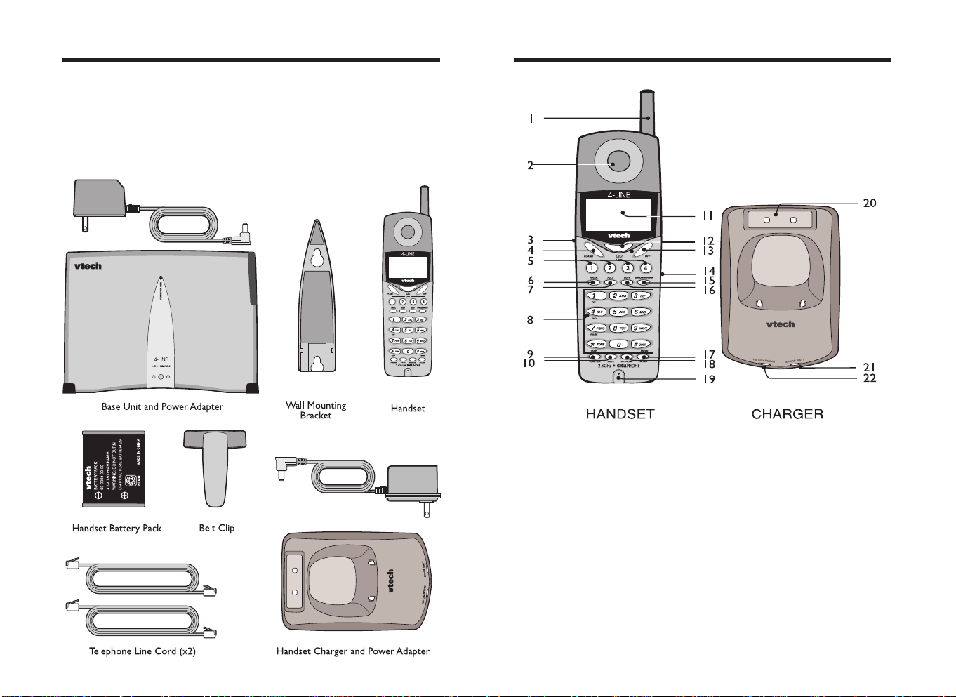
Parts Check List
The Handset and Handset Charger Layout
1. Base Unit and power adapter
2. Handset
3. Handset Charger and power adapter
4. Handset battery pack
5. Wall Mount Bracket
6. Telephone line cord (x2)
7. Belt clip
. Antenna
1
2. Earpiece
3. Volume/Scroll Keys
4. FLASH
5. Line 1,2,3,4
6. REDIAL
7. HOLD
8. Dialing Keys (0-9)
9. FUNCTION
10. PROG
11. LCD Display
12. CID
13. OFF
14. Headset Jack (2.5mm)
15. SPEAKERPHONE
16. MUTE
17. CALLER
18. INTERCOM
19. Microphone
20. Spare Battery Charging Slot
21. SPARE BATT LED
22. HS CHARGING LED
4
5
Page 4
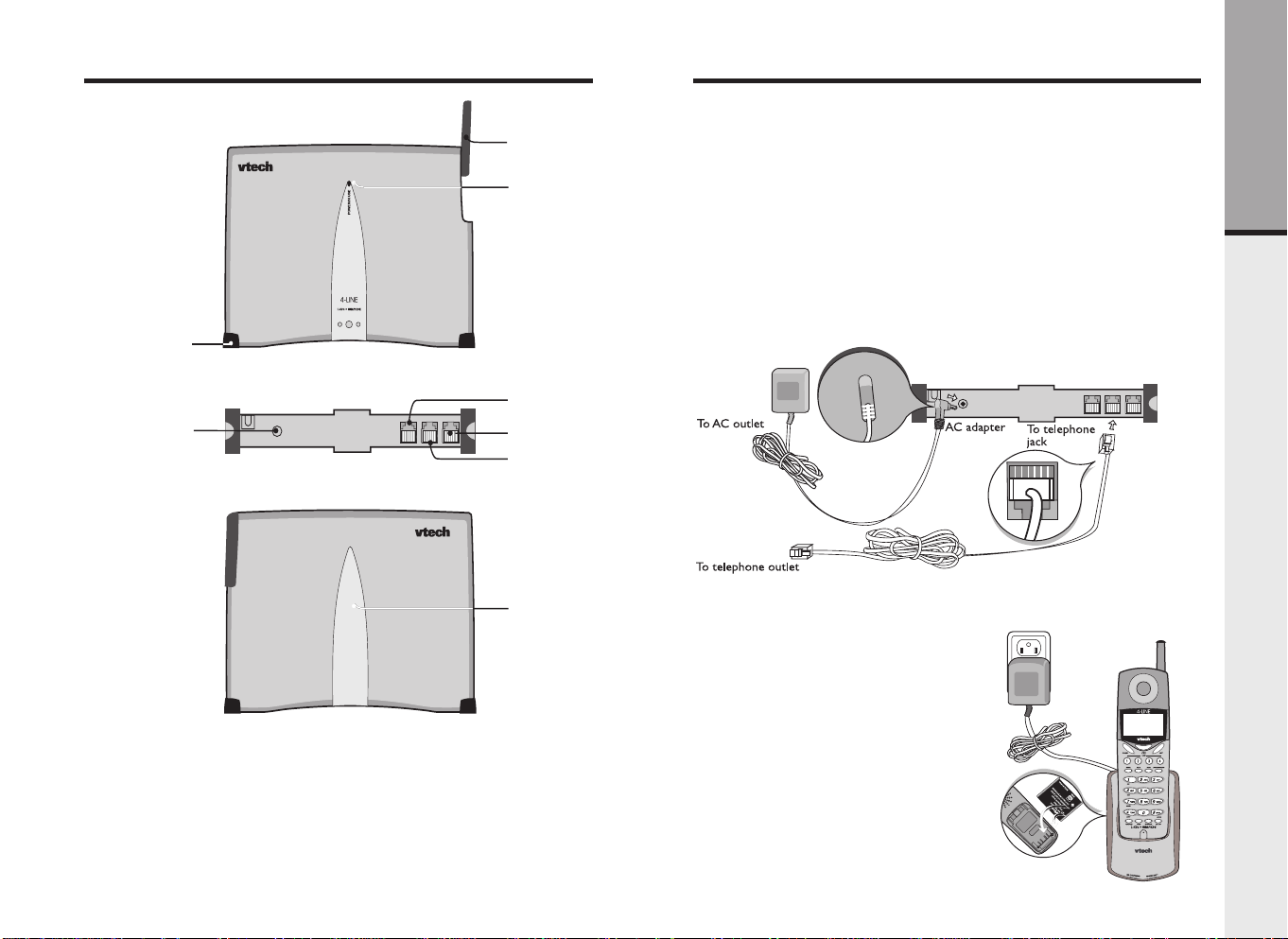
The Base Unit Layout
FRONT
1
2
Setup
Connection of Phone and Power Lines
3
4
5
6
7
•VT 40-2421 setup
1. Plug the AC power adapter into an electrical outlet, and the DC connector
into the back of the base unit.
2. There are three modular telephone connections on the base unit L1/L2, L3/
L4 and an AUX dataport to allow direct connection of a fax or modem. The
dataport is linked to the L2 connection only.
3. Plug one end of the telephone line cord(s) into the jack(s) on the back of
the base unit. Plug the other end of this cord into the wall jack.
4. Plug the AC power adapter into an electrical outlet, and the DC connector
into the back of the handset charger.
5. Install handset battery and allow handset to charge for at least 15 hours
initially.
Getting Started
BACK
1. Rubber Foot
2. DC Connector
3. Antenna
4. Power/ In use Indicator
. L3/L4 Telephone Jack
5
6. AUX Dataport Jack
7. L1/L2 Telephone Jack
8. Wall Mount Cover
6
8
•VT 40-2420 setup
1. Plug the AC power adapter into an
electrical outlet, and the DC
connector into the back of the
handset charger.
2. Install handset battery and allow
handset to charge for at least 15
hours initially.
7
Page 5
Setup
Setup
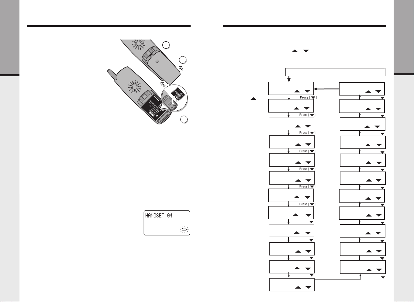
Installation of Battery Pack in Handset
Follow the steps below:
1. Remove the battery cover by
1
pressing on the indent and
sliding downward.
2. Place the new battery pack in the
Getting Started
handset with the metal contacts
aligned with the charge contacts
in the battery compartment.
3. Replace the battery cover by
sliding it upwards.
4. If the new battery pack is not
already charged, place the
handset in the handset charger,
and allow it to charge for 15
hours. After initial charge, a
maintenance charge of 8 hours
should be sufficient.
The original Handset that is shipped with your VT 40-2421 system will be
automatically registered to the Base. This Handset is HANDSET 1.
As you register additional Handsets to the system, you should assign extension
numbers in the following order: HANDSET 2, HANDSET 3, HANDSET 4,
HANDSET 5, HANDSET 6, HANDSET 7, HANDSET 8, HANDSET 9,
HANDSET 10, HANDSET 11, and finally HANDSET 12. See Handset ID and
Handset Name.
Charging of Handset Battery Pack
The Handset of your VT 40-2421 cordless telephone is powered by a rechargeable
battery pack. It charges automatically whenever the Handset is in the Charger.
You should charge the battery pack for 15 hours when you first receive your
phone. You may also need to charge the battery under the following conditions:
• The low battery message is displayed:
• The handset seems completely dead, the LCD
is completely clear and does not activate when
you press the keys.
IMPORTANT:
1. Do not dispose of a battery pack in a fire, the cell may explode.
2. Do not open or mutilate the battery pack. Toxic substances may be released,
causing harm to eyes or skin.
3. Exercise care in handling battery packs in order to prevent an accidental
short of the charge contacts, potentially causing the battery pack to
overheat.
4. Do not dispose of this battery pack into household garbage.
8
System Programming
The VT 40-2421 / 40-2420 is controlled by a sophisticated menu structure. To
access the program mode, start with the handset in idle (off) mode and then
press the PROG key. Use the ( / ) volume keys to navigate through
the menu, and the # key to make selections. At any time, you can press the
3
OFF key to exit without saving changes. If you do not press a key for 30 seconds,
the system will automatically exit program and return to idle mode.
Getting Started
Flow chart of program mode: If the handset is in idle (off) mode, press PROG.
• To return to the
previous program
mode, press key.
• To exit program
mode, press OFF.
2
MEMORY
[ ]/[ ]
CO LINE 1 RING
ON
[ ]/[ ]
CO LINE 2 RING
[ ]/[ ]
ON
CO LINE 3 RING
ON
[ ]/[ ]
CO LINE 4 RING
[ ]/[ ]
ON
RINGER TYPE
[ ]/[ ]
1
HS SECURITY CODE
[ ]/[ ]
EMPTY
BU SECURITY CODE
[ ]/[ ]
HANDSET ID
[ ]/[ ]
01
HANDSET NAME
Press [ ]
Press [ ]
[ ]/[ ]
HOLD REMINDER
30 SEC
TONE/PULSE
TONE
Press [ ]
[ ]/[ ]
Press [ ]
[ ]/[ ]
9
BASE RESET
[ ]/[ ]
HANDSET RESET
Press [ ]
[ ]/[ ]
AUTO PICKUP
[ ]/[ ]
OFF
LINE IN USE
[ ]/[ ]
ON
LOCAL AREA CODE5
EMPTY
LOCAL AREA CODE4
EMPTY
LOCAL AREA CODE3
EMPTY
LOCATL AREA CODE2
EMPTY
LOCAL AREA CODE1
EMPTY
HOME AREA CODE
EMPTY
FLASH TIME
600ms
Press [ ]
Press [ ]
Press [ ]
[ ]/[ ]
Press [ ]
[ ]/[ ]
Press [ ]
[ ]/[ ]
Press [ ]
[ ]/[ ]
Press [ ]
[ ]/[ ]
Press [ ]
[ ]/[ ]
Press [ ]
[ ]/[ ]
Press [ ]
Page 6
Setup
Setup
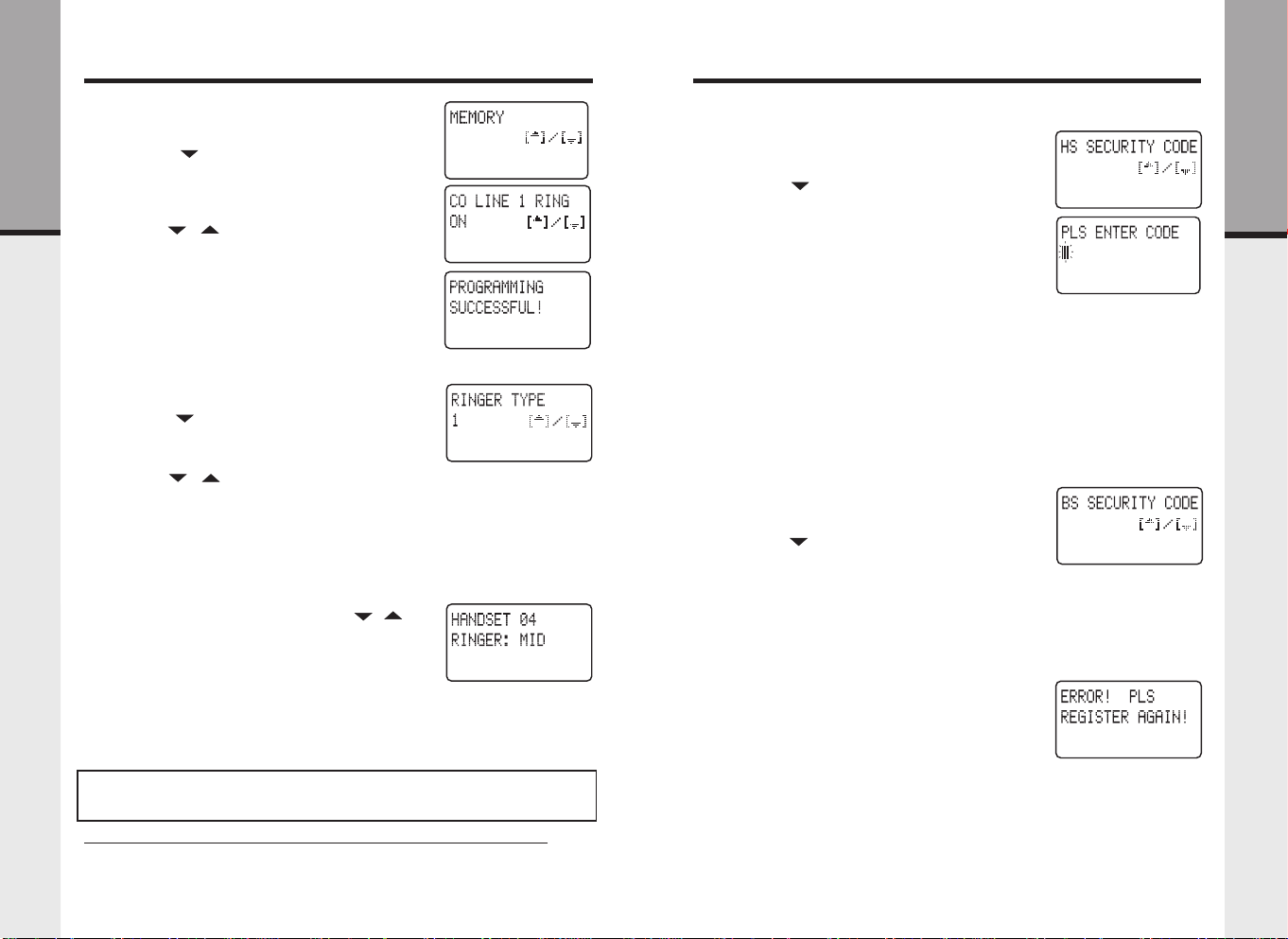
Ringer ON/OFF
• Access program mode
• Press the ( ) key until you see
RINGRING
RING
RINGRING
• Press the # key to change settings. The cursor
Getting Started
will blink to the right of the current setting
• Use the ( / ) volume keys to select either
ONON
OFFOFF
ON or
OFF.
ONON
OFFOFF
• Press the # key to confirm choice.
PROGRAMMING SUCCESSFUL!PROGRAMMING SUCCESSFUL!
•
PROGRAMMING SUCCESSFUL! is displayed.
PROGRAMMING SUCCESSFUL!PROGRAMMING SUCCESSFUL!
• Repeat the above steps to set ringers for LINE
2, LINE 3 and LINE 4
Ringer Type
• Access program mode
• Press the ( ) key until you see
• Press the # key to change settings. The cursor
will blink to the right of the current ringer setting
• Use the ( / ) volume keys to sample the
four ringer types
• Press the # key to confirm choice
PROGRAMMING SUCCESSFUL!PROGRAMMING SUCCESSFUL!
•
PROGRAMMING SUCCESSFUL! is displayed, and
PROGRAMMING SUCCESSFUL!PROGRAMMING SUCCESSFUL!
the selected ringer type will be played once.
Ringer Volume Control
• From the idle (off) mode press the ( / )
volume keys to select volume level LOW / MID
/ HIGH
Handset and Base Unit Security Codes
The VT 40-2421 is an advanced telephone system, which uses a unique 6-digit
security code for operation. The VT 40-2421 Handset and Base unit are factory
programmed with a default security code, which allows you use the system after
charging.
NOTE: When using multiple Handsets, you must assign a 6-digit system
security code (shared by all Handsets and Base Unit), and each Handset must
be assigned its own unique HANDSET ID (extension) number.
Assigning the Handset Security Code and Loading into the Base Unit
• Disconnect the AC power to the base unit.
CO LINE 1CO LINE 1
CO LINE 1
CO LINE 1CO LINE 1
RINGER TYPERINGER TYPE
RINGER TYPE
RINGER TYPERINGER TYPE
• Made sure that only HANDSET 01 has a battery
pack installed. All other Handsets need to have
their battery packs removed during this process.
• Access program mode
• Press the ( ) key until you see
CODECODE
CODE
CODECODE
• Press the # key to change settings. You will be
prompted to
to input a 6-digit security code. This security code
is selected by you, so please choose a security code
that you will remember. Also, record the
SECURITY CODESECURITY CODE
SECURITY CODE in the space below for future
SECURITY CODESECURITY CODE
reference.
SECURITY CODE:________________
• Use the number keys to enter the 6 digit
SECURITY CODE SECURITY CODE
SECURITY CODE (i.e. 123456, 223455, 000005, etc.)
SECURITY CODE SECURITY CODE
• Press the # key to confirm choice
PROGRAMMING SUCCESSFUL!PROGRAMMING SUCCESSFUL!
•
PROGRAMMING SUCCESSFUL! is displayed.
PROGRAMMING SUCCESSFUL!PROGRAMMING SUCCESSFUL!
You now need to load the
the Base Unit, using HANDSET 01. Please follow these
steps:
• The Base Unit power should still be disconnected.
• Access program mode
• Press the ( ) key until you see
CODECODE
CODE
CODECODE
• Reconnect the Base Unit power. Once the power
is connected, you have only 10 seconds to
complete the next step.
• With
01, press the # key. The
now been loaded into the Base Unit.
PROGRAMMING SUCCESSFUL!PROGRAMMING SUCCESSFUL!
•
PROGRAMMING SUCCESSFUL! is displayed.
PROGRAMMING SUCCESSFUL!PROGRAMMING SUCCESSFUL!
• If you fail in loading the
the Base Unit,
is displayed, you have to repeat the above 6 steps
to load into the Base Unit until
SUCCESSFUL!SUCCESSFUL!
SUCCESSFUL! is displayed.
SUCCESSFUL!SUCCESSFUL!
Handset ID
The VT 40-2421 system supports up to 12 extension handsets. In order to use
the multiple handset capability of this product, you must first assign a 6-digit
security code. Please refer to Handset and Base Unit Security Codes before
proceeding with Handset ID.
PLS ENTER CODEPLS ENTER CODE
PLS ENTER CODE, waiting for you
PLS ENTER CODEPLS ENTER CODE
HS SECURITY CODEHS SECURITY CODE
HS SECURITY CODE into
HS SECURITY CODEHS SECURITY CODE
BS SECURITY CODEBS SECURITY CODE
BS SECURITY CODE displayed on HANDSET
BS SECURITY CODEBS SECURITY CODE
ERROR! PLS REGISTER AGAIN!ERROR! PLS REGISTER AGAIN!
ERROR! PLS REGISTER AGAIN!
ERROR! PLS REGISTER AGAIN!ERROR! PLS REGISTER AGAIN!
HS SECURITY CODEHS SECURITY CODE
HS SECURITY CODE has
HS SECURITY CODEHS SECURITY CODE
HS SECURITY CODEHS SECURITY CODE
HS SECURITY CODE into
HS SECURITY CODEHS SECURITY CODE
HS SECURITYHS SECURITY
HS SECURITY
HS SECURITYHS SECURITY
HSHS
HS
HSHS
HSHS
HS
HSHS
BS SECURITYBS SECURITY
BS SECURITY
BS SECURITYBS SECURITY
PROGRAMMINGPROGRAMMING
PROGRAMMING
PROGRAMMINGPROGRAMMING
Getting Started
10
11
Page 7
Setup
Setup
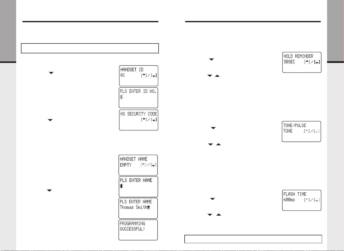
When multiple handsets are added to the VT 40-2421 system, you must first
assign a unique ID (extension number) for each Handset, and then enter the
system security code. Valid ID numbers are 01, 02, 03, 04, 05, 06, 07, 08, 09, 10,
11 and 12.
CAUTION: Be careful not to assign the same Handset ID number to more than
one Handset.
Getting Started
• If you have not already selected a system security code, follow the steps
in Handset and Base Security Codes above. Then do the following:
• Access program mode
• Press the ( ) key until you see
• Press the # key to change settings. The cursor will
blink to the right of the current
setting
• You will be prompted to
• Use the number keys to enter the two digit ID
code (i.e. 01, 02...12)
• Press the # key to confirm choice
PROGRAMMING SUCCESSFUL!PROGRAMMING SUCCESSFUL!
•
PROGRAMMING SUCCESSFUL! is displayed.
PROGRAMMING SUCCESSFUL!PROGRAMMING SUCCESSFUL!
• Press the ( ) key until you see
CODESCODES
CODES
CODESCODES
• Press the # key. You will be prompted to
ENTER CODEENTER CODE
ENTER CODE, waiting for you to input the 6 digit
ENTER CODEENTER CODE
security code you previously selected.
• Use the number keys to enter the same 6 digit
HS SECURITY CODE HS SECURITY CODE
HS SECURITY CODE for this VT40-2421 system.
HS SECURITY CODE HS SECURITY CODE
• Press the # key to confirm choice
PROGRAMMING SUCCESSFUL!PROGRAMMING SUCCESSFUL!
•
PROGRAMMING SUCCESSFUL! is displayed.
PROGRAMMING SUCCESSFUL!PROGRAMMING SUCCESSFUL!
Handset Name
If you want to assign a name for a handset, follow
the steps below:
• Access program mode
• Press the ( ) key until you see
• Press the # key to change settings. The cursor
will blink to the right of the current HANDSET
NAME setting.
• You will be prompted to
• Use the digit keys to 'spell' the name. Names can
be up to 16 characters. To enter a specific set of
characters, see Speed Dial Memory: To Program
or Edit a Speed Memory Location.
• Press the # key to confirm the name.
PROGRAMMING SUCCESSFUL!PROGRAMMING SUCCESSFUL!
•
PROGRAMMING SUCCESSFUL! is displayed.
PROGRAMMING SUCCESSFUL!PROGRAMMING SUCCESSFUL!
HANDSET IDHANDSET ID
HANDSET ID
HANDSET IDHANDSET ID
HANDSET IDHANDSET ID
HANDSET ID
HANDSET IDHANDSET ID
PLS ENTER ID NOPLS ENTER ID NO
PLS ENTER ID NO
PLS ENTER ID NOPLS ENTER ID NO
HS SECURITYHS SECURITY
HS SECURITY
HS SECURITYHS SECURITY
PLSPLS
PLS
PLSPLS
HANDSET NAMEHANDSET NAME
HANDSET NAME
HANDSET NAMEHANDSET NAME
PLS ENTER NAMEPLS ENTER NAME
PLS ENTER NAME
PLS ENTER NAMEPLS ENTER NAME
12
Hold Reminder
The VT 40-2421 system has an option to activate a hold reminder, which plays
a brief tone to alert you that a call is on hold. Each handset is programmed
independently. All handsets linked to the system will be alerted at the selected
interval (15sec, 30sec, 45sec, or 60sec) unless OFF is selected.
• Access program mode
• Press the ( ) key until you see
• Press the # key to change settings. The cursor will
blink to the right of the current ringer setting.
• Use the ( / ) volume keys to cycle through
the five options (15sec, 30sec, 45sec, 60sec, OFF).
• Press the # key to confirm choice
PROGRAMMING SUCCESSFUL!PROGRAMMING SUCCESSFUL!
•
PROGRAMMING SUCCESSFUL! is displayed.
PROGRAMMING SUCCESSFUL!PROGRAMMING SUCCESSFUL!
Tone/Pulse
If you have touch tone service, do not change the setting of this mode. If you
have rotary(Pulse) service, you have to access TONE/PULSE mode and set to
PULSE.
• Access program mode
• Press the ( ) key until you see
• Press the # key to change settings. The cursor will
blink to the right of the current ringer setting.
• Use the ( / ) volume keys to choose
PULSEPULSE
or
PULSE
PULSEPULSE
• Press the # key to confirm choice
PROGRAMMING SUCCESSFUL!PROGRAMMING SUCCESSFUL!
•
PROGRAMMING SUCCESSFUL! is displayed.
PROGRAMMING SUCCESSFUL!PROGRAMMING SUCCESSFUL!
Flash Time
This function is commonly used with service such as Call Waiting. The default
setting for flash time is 600ms. It is unlikely that you will need to change this
setting, however, if required you can adjust the flash time from 100ms to 900ms
in 100ms intervals.
• Access program mode
• Press the ( ) key until you see
• Press the # key to change settings. The cursor will
blink to the right of the current setting.
• Use the ( / ) volume keys to choose flash
setting (100ms, 200ms...900ms)
• Press the # key to confirm choice
PROGRAMMING SUCCESSFUL!PROGRAMMING SUCCESSFUL!
•
PROGRAMMING SUCCESSFUL! is displayed.
PROGRAMMING SUCCESSFUL!PROGRAMMING SUCCESSFUL!
Note: Please consult your local telephone service provider when you want to
change the Flash Time.
HOLD REMINDERHOLD REMINDER
HOLD REMINDER
HOLD REMINDERHOLD REMINDER
TONE/PULSETONE/PULSE
TONE/PULSE
TONE/PULSETONE/PULSE
TONETONE
TONE
TONETONE
FLASH TIMEFLASH TIME
FLASH TIME
FLASH TIMEFLASH TIME
13
Getting Started
Page 8

Setup
Setup
Home Area Code
If you live in an area where you dial calls within your own area code by dialing
7 digits (no area code), follow these steps:
• Access program mode
• Press the ( ) key until you see
Getting Started
• Press the # key to change settings. The cursor will
blink to the right of the current setting.
• Use the number keys to enter your home area code
• Press the # key to confirm choice
PROGRAMMING SUCCESSFUL!PROGRAMMING SUCCESSFUL!
•
PROGRAMMING SUCCESSFUL! is displayed.
PROGRAMMING SUCCESSFUL!PROGRAMMING SUCCESSFUL!
Local Area Codes
You can program up to five local area codes. Please note that the
CODECODE
CODE should be empty if you are using the local area programming. If you live
CODECODE
in an area where all local calls require 10 digits (area code plus phone number,
without dialing “1” first) follow these steps:
• Access program mode
• Press the ( ) key until you see
CODE1CODE1
CODE1
CODE1CODE1
• Press the # key to change settings. The cursor will
blink to the right of the current setting.
• Use the number keys to enter your local area code
• Press the # key to confirm choice
PROGRAMMING SUCCESSFUL!PROGRAMMING SUCCESSFUL!
•
PROGRAMMING SUCCESSFUL! is displayed.
PROGRAMMING SUCCESSFUL!PROGRAMMING SUCCESSFUL!
• Repeat the above steps for LOCAL AREA CODE2,
CODE3, CODE4 and CODE5
Line in Use Detection
There is a
(parallel extension) is in use.
• Access program mode
• Press the ( ) key until you see
• Press the # key to change settings. The cursor will
• Use the ( / ) volume keys to choose
• Press the # key to confirm choice
•
LINE IN USELINE IN USE
LINE IN USE indication when another telephone on the same line
LINE IN USELINE IN USE
blink to the right of the current setting.
OFFOFF
or
OFF
OFFOFF
PROGRAMMING SUCCESSFUL!PROGRAMMING SUCCESSFUL!
PROGRAMMING SUCCESSFUL! is displayed.
PROGRAMMING SUCCESSFUL!PROGRAMMING SUCCESSFUL!
HOME AREA CODEHOME AREA CODE
HOME AREA CODE
HOME AREA CODEHOME AREA CODE
LOCAL AREALOCAL AREA
LOCAL AREA
LOCAL AREALOCAL AREA
LINE IN USELINE IN USE
LINE IN USE
LINE IN USELINE IN USE
ONON
ON
ONON
14
HOME AREAHOME AREA
HOME AREA
HOME AREAHOME AREA
Auto Pick Up
Select this option and set to ON if you want the handset to automatically answer
calls when the handset is lifted from the cradle (without having to press LINE
or SPEAKERPHONE).
• Access program mode
• Press the ( ) key until you see
• Press the # key to change settings. The cursor will
blink to the right of the current setting.
• Use the ( / ) volume keys to choose
OFFOFF
OFF
OFFOFF
• Press the # key to confirm choice
PROGRAMMING SUCCESSFUL!PROGRAMMING SUCCESSFUL!
•
PROGRAMMING SUCCESSFUL! is displayed.
PROGRAMMING SUCCESSFUL!PROGRAMMING SUCCESSFUL!
Handset Reset
Select this option to reset a single handset to factory default settings.
NOTE: After selecting this option, you will need to re-assign the Handset ID
and re-load the system security code.
• Access program mode
• Press the ( ) key until you see
• Press the # key to change settings
• You will be prompted to
• To exit without resetting press OFF key
• Press the # key to confirm choice
PROGRAMMING SUCCESSFUL!PROGRAMMING SUCCESSFUL!
•
PROGRAMMING SUCCESSFUL! is displayed.
PROGRAMMING SUCCESSFUL!PROGRAMMING SUCCESSFUL!
Base Reset
Select this option to reset base settings to factory default.
NOTE: After selecting this option, you will need to re-program the system
security code. You will also need to re-assign a unique Handset ID (extension)
number for each handset, and then re-load the 6 digit system security code
into ALL SYSTEM HANDSETS.
• Access program mode
• Press the ( ) key until you see
• Press the # key to change settings
• You will be prompted to
• To exit without resetting press OFF key
• Press the # key to confirm choice
PROGRAMMING SUCCESSFUL!PROGRAMMING SUCCESSFUL!
•
PROGRAMMING SUCCESSFUL! is displayed.
PROGRAMMING SUCCESSFUL!PROGRAMMING SUCCESSFUL!
AUTO PICKUPAUTO PICKUP
AUTO PICKUP
AUTO PICKUPAUTO PICKUP
HANDSET RESETHANDSET RESET
HANDSET RESET
HANDSET RESETHANDSET RESET
RESET YES?RESET YES?
RESET YES?
RESET YES?RESET YES?
BASE RESETBASE RESET
BASE RESET
BASE RESETBASE RESET
RESET YES?RESET YES?
RESET YES?
RESET YES?RESET YES?
ONON
ON or
ONON
15
Getting Started
Page 9

Setup
Placing Calls
Do Not Disturb (DND)
If you do no want a particular handset to receive
calls, activate the DND function by doing the
following:
• Press FUNCTION key followed by the 4(DND)
key.
Getting Started
• The handset will display
• To cancel the DND press FUNCTION followed
by the 4(DND) key again.
Note: When DND is enabled, you will not be able
to pre-dial numbers.
Wall Mounting
The Wall Mount bracket is designed for use on standard Wall Mount plates only.
• Remove the wall mount cover at the back of the Base Unit
• Line up the tabs on the wall mount bracket with the holes at the back of
the Base Unit. Snap the wall mount bracket firmly in place.
• Mount the Base Unit on the wall. Position the Base Unit so the mounting
stubs will fit into the holes on the wall mount bracket. Slide Base Unit down
on the mounting stubs until it locks into placs.
DO NOT DISTURB!DO NOT DISTURB!
DO NOT DISTURB!
DO NOT DISTURB!DO NOT DISTURB!
Remove Wall Mount Cover
Live Dialing
• Press the desired LINE key or SPK.PHONE (for
handsfree on next available line). Listen for dial
tone.
• Enter the number you wish to dial
• To end a call press OFF or place handset in charger
cradle
Pre-Dialing
• Enter the number you wish to dial on the display.
• Press the desired LINE key or SPK.PHONE (for
handsfree on next available line).
• To end a call press OFF or place handset in charger
cradle
Basic Operations
Basic Operations
Wall Mount
16
Bracket
17
Page 10
Receiving Calls
Mute / Hold / Intercom
• When you have an incoming call, the line and
icon will appear in the display above the
corresponding LINE key. For example, if there
is a call on LINE 2, the line 2 and icon
above LINE 2 will be illuminated.
• Also, if you have Caller ID service, the display
will show L1, L2, L3 or L4 to the left of the Caller
ID number information.
• To answer an incoming call from an IDLE
handset, do either of the following:
* Press the appropriate LINE key
* Press any key to answer the ringing line
* Press SPK.PHONE (for handsfree on ringing
line).
• To answer an incoming call from an ACTIVE
handset (on another call)
Basic Operations
* Press OFF to terminate the current call.
Or,
* Place the current call on hold by pressing
HOLD.
Then do either of the following:
* Press the appropriate LINE key
* Press any key to answer the ringing line
* Press SPK.PHONE (for handsfree on ringing
line).
NOTE: If you have
handset will automatically answer the first ringing
line, when lifted from the charge cradle. See Auto
Pick up Line Function.
AUTO PICKUPAUTO PICKUP
AUTO PICKUP set to
AUTO PICKUPAUTO PICKUP
ONON
ON, a ringing
ONON
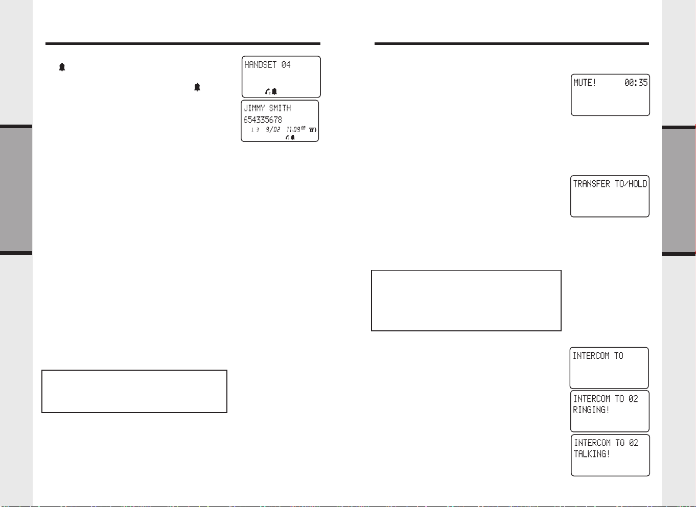
Mute
During an active call, press the MUTE key to
temporarily disable the handset microphone.
MUTE!MUTE!
MUTE! Will be displayed.
MUTE!MUTE!
Pres the MUTE key again to resume normal two way
conversation.
Hold
• To place an active call on hold, press the HOLD
key.
• While a call is on hold the handset will display
TRANSFER TO/HOLDTRANSFER TO/HOLD
TRANSFER TO/HOLD and the corresponding line
TRANSFER TO/HOLDTRANSFER TO/HOLD
icon will flash.
• If you have HOLD REMINDER enabled, you will
hear an alert tone at the specified interval (15sec,
30sec, 45sec, or 60sec).
• Once a call is on hold, any handset can then access
the call by pressing the corresponding line key.
Note: If a call is placed on hold for more than 3
minutes, all handsets will receive a Recall Ring tone
that serves as a reminder that a call remains on hold.
Also, if a call is left on hold for more than 5 minutes,
the VT 40-2421 system will automatically disconnect
the line.
Intercom
To establish an intercom call
• Press the INTERCOM key, followed by the
handset number (01..12).
• Once the other handset answers, the handset will
• To end the intercom call, either handset can press
display
OFF.
TALKING!TALKING!
TALKING!
TALKING!TALKING!
Basic Operations
18
19
Page 11

Speed Dial Memory
Speed Dial Memory
Each handset in the VT 40-2421 / 40-2420 system can
store up to 20 names and numbers in a private speed
dial memory. This is important to note, as each
handset must be programmed separately.
To Program or Edit a Speed Memory Location
• Access program mode
• Press # to select
• Use the ( / ) volume keys to scroll to a
desired memory location (01...20)
• Press # select the Speed Memory location
• You will be prompted to enter
• Use the digit keys to ‘spell’ the name. Names
can be up to 16 characters. Use ( / ) volume
keys move left or right in the name field.
Characters and symbols for name entry are
located on the following number keys:
Basic Operations
Key Characters
1 SPACE - ‘ & . ( ) @ 1
2 A, B, C, a, b, c, 2
3 D, E, F, d, e, f, 3
4 G, H, I, g, h, i, 4
5 J, K, L, j, k, l, 5
6 M, N, O, m, n, o, 6
7 P, Q, R, S, p, q, r, s, 7
8
9 W, X, Y, Z, w, x, y, z, 9
0 0
* *
# #
• Press the # key to confirm the name.
• Using the digit keys enter
• To enter a pause, press the FUNCTION key
T, U, V, t, u, v, 8
followed by the 7 (PAUSE) key
SPEED MEMORYSPEED MEMORY
SPEED MEMORY
SPEED MEMORYSPEED MEMORY
NUMBERNUMBER
NUMBER when prompted
NUMBERNUMBER
NAME?NAME?
NAME?
NAME?NAME?
• Press the # key to confirm number
PROGRAMMING SUCCESSFUL!PROGRAMMING SUCCESSFUL!
•
PROGRAMMING SUCCESSFUL! is displayed
PROGRAMMING SUCCESSFUL!PROGRAMMING SUCCESSFUL!
To Delete a Speed Memory Location
• Access program mode
• Press # to select
• Use the ( / ) volume keys to scroll to a
desired memory location (01...20)
• Press the FUNCTION key followed by the 1 (DEL)
key to delete
• Press # to confirm deletion
PROGRAMMING SUCCESSFUL!PROGRAMMING SUCCESSFUL!
•
PROGRAMMING SUCCESSFUL! is displayed; or press
PROGRAMMING SUCCESSFUL!PROGRAMMING SUCCESSFUL!
OFF key to exit without deleting
To Delete ALL Speed Memory Locations
• Access
• Press # to select
• Press the FUNCTION key followed by the 1 (DEL)
• Press # to confirm deletion
•
To Dial from Speed Memory
• Access program mode
• Press # to select
• Use the ( / ) volume keys to scroll to a
• Press the desired LINE key or SPK.PHONE (for
• To end a call press OFF key or place handset in
programprogram
program mode
programprogram
key to delete
PROGRAMMING SUCCESSSFUL!PROGRAMMING SUCCESSSFUL!
PROGRAMMING SUCCESSSFUL! is displayed; or
PROGRAMMING SUCCESSSFUL!PROGRAMMING SUCCESSSFUL!
press OFF key to exit without deleting
desired memory location (01...20)
handsfree on next available line)
charger cradle
SPEED MEMORYSPEED MEMORY
SPEED MEMORY
SPEED MEMORYSPEED MEMORY
SPEED MEMORYSPEED MEMORY
SPEED MEMORY
SPEED MEMORYSPEED MEMORY
SPEED MEMORYSPEED MEMORY
SPEED MEMORY
SPEED MEMORYSPEED MEMORY
Basic Operations
20
21
Page 12

Caller ID
Caller ID
The VT 40-2421 system is capable of displaying the name and/or number of
the party calling before you answer the phone (Caller ID). It is also capable of
displaying Caller ID information in conjunction with a Call Waiting alert signal
(Call Waiting Caller ID). With Call Waiting Caller ID, the Caller ID data is
displayed so you can decide whether to answer the incoming call, or continue
with your current conversation. The VT 40-2421 system stores the last 50 calls
with name, number and time/date of each call received.
NOTES ABOUT CALLER ID & CALL WAITING CALLER ID
These are subscription services, provided by most regional telephone service
providers. You must subscribe to these services to get the benefits of these
features. If you do not subscribe to Caller ID services, you can still use your
VT 40-2421 system and the other features it offers. Due to regional incompatibilities,
Caller ID information may not be available for every call you receive. In addition,
the calling party may intentionally block their name and phone number from
being sent.
Some of the special Caller ID messages you may receive include:
NO CALLER INFONO CALLER INFO
NO CALLER INFO
NO CALLER INFONO CALLER INFO
and/or number information is not received by the VT 40-2421 system.
PRIVATEPRIVATE
PRIVATE
PRIVATEPRIVATE
name and phone number from being sent.
If more than one line is ringing at the same time, you can review the incoming
Caller ID information by pressing the CALLER key. Each press of the CALLER
key will switch between the Caller ID information from currently ringing lines,
and the handset idle display. To answer a particular line, simply press the
Advanced Operations
corresponding LINE key.
Caller ID display of inbound call
As a call is received on the VT 40-2421 system, the Caller ID information is
displayed in the following format:
: May be displayed if the calling party has intentionally blocked their
OUT OF AREAOUT OF AREA
OUT OF AREA
or
OUT OF AREAOUT OF AREA
: May be displayed if either the name
Reviewing Caller ID Memory
• Press the CID key
• The display will show a counter of calls stored
Caller ID memory.
ALL CIDALL CID
ALL CID
*
ALL CIDALL CID
ID records stored
NEW CIDNEW CID
NEW CID
*
NEW CIDNEW CID
that have been received since you last reviewed
the Caller ID memory.
• Use the ( / ) volume keys to scroll through
Caller ID memory.
• Pressing the arrow will start with the most
recent call received.
• Pressing the arrow will start with the oldest
call received.
• When you reach the end of the list, you can ‘wrap
around’ to the beginning by pressing the ( /
Dialing from Caller ID Memory
• Press the CID key
• Use the ( / ) volume keys to scroll through
Caller ID memory.
• Press an available line key (L1, L2, L3, L4) to
automatically dial the displayed number.
• You can also press the SPK.PHONE key to
activate the handset speakerphone on the next
available line.
• Press OFF key to end the call.
Storing Caller ID Records into Speed Dial Memory
• Press the CID key
• Use the ( / ) volume keys to locate the
Caller ID record to be stored into Speed Dial
memory.
: Represents the total number of Caller
: Represents the total number of calls
) key again.
Advanced Operations
22
23
Page 13

Caller ID
Visual Message Waiting Indication
• Press the PROG key
• Press # to enter
• Use the ( / ) volume keys to locate the
memory location (01..20) where you wish to store
the Caller ID record
• Press the CID key. The Caller ID record will be
displayed along with the memory location
number.
• Press # to proceed.
• Review the displayed name. Make changes if
necessary, and then press the # key.
• Review the displayed number. Make changes
if necessary, and then press the # key
PROGRAMMING SUCCESSFUL!PROGRAMMING SUCCESSFUL!
•
PROGRAMMING SUCCESSFUL! is displayed.
PROGRAMMING SUCCESSFUL!PROGRAMMING SUCCESSFUL!
Deleting a Single Caller ID Record
• Press the CID key
• Use the ( / ) volume keys to locate the
Caller ID record to be deleted.
• Press FUNCTION followed by the 1 (DEL) key
to delete
• The name of the selected memory location will
be displayed.
• Press # to confirm deletion
DELETED!DELETED!
•
DELETED! is displayed; or press OFF to exit
DELETED!DELETED!
Advanced Operations
without deleting
Deleting All Caller ID Records
• Press the CID key
• Press FUNCTION followed by the 1 (DEL) key
to delete all Caller ID records.
DELETE ALL CID?DELETE ALL CID?
•
DELETE ALL CID? will be displayed.
DELETE ALL CID?DELETE ALL CID?
• Press # to confirm deletion
SPEED MEMORYSPEED MEMORY
SPEED MEMORY.
SPEED MEMORYSPEED MEMORY
The VT 40-2421 is compatible with optional voicemail
service provided by some local telephone companies.
If you subscribe to this service, and you have new,
unplayed messages in your voicemail, a Visual
Message Waiting Indicator(VMWI) signal is
transmitted by your local telephone company.
The VT 40-2421 detects a VMWI signal and activates
a the Message Waiting indicator on the Handset(s).
After you check your messages, the Message Waiting
indicator will automatically turn off.
Please note that whenever new, unplayed messages
are stored in your voicemail, the local Telephone
Company will continue to send a VMWI signal.
If after reviewing unplayed messages, the
WAITINGWAITING
WAITING display remains, you can manually delete
WAITINGWAITING
the indicator as follows:
- Start from an idle mode with
actively being displayed.
- Press FUNCTION followed by 1(DEL) to delete
DEL MSG DISPLAY?DEL MSG DISPLAY?
-
DEL MSG DISPLAY? is displayed.
DEL MSG DISPLAY?DEL MSG DISPLAY?
* Press 1 to delete the
for LINE 1
* Press 2 to delete the
for LINE 2
* Press 3 to delete the
for LINE 3
* Press 4 to delete the
for LINE 4
* Press 0 to delete the
for ALL lines
MESSAGE WAITINGMESSAGE WAITING
MESSAGE WAITING indicator
MESSAGE WAITINGMESSAGE WAITING
MESSAGE WAITINGMESSAGE WAITING
MESSAGE WAITING indicator
MESSAGE WAITINGMESSAGE WAITING
MESSAGE WAITINGMESSAGE WAITING
MESSAGE WAITING indicator
MESSAGE WAITINGMESSAGE WAITING
MESSAGE WAITINGMESSAGE WAITING
MESSAGE WAITING indicator
MESSAGE WAITINGMESSAGE WAITING
MESSAGE WAITINGMESSAGE WAITING
MESSAGE WAITING indicator
MESSAGE WAITINGMESSAGE WAITING
MESSAGE WAITINGMESSAGE WAITING
MESSAGE WAITING
MESSAGE WAITINGMESSAGE WAITING
MESSAGEMESSAGE
MESSAGE
MESSAGEMESSAGE
Advanced Operations
24
25
Page 14

Transfer
Conference
Announced Transfer
• While on an active call, press the INTERCOM key followed by the handset
number you wish to call. The active call will be automatically placed on
hold.
• When the other handset answers, simply announce there is a call for them
on a particular line.
• As soon as the other handset answers the held line, the intercom will be
automatically terminated.
• You can also press OFF to end the intercom at any time.
Blind Transfer
• Place an active call on hold, by pressing the
HOLD key.
• The handset will display
• Enter the handset number you wish to transfer
the call to (01..12)
• The call will be automatically transferred to the
selected handset
TRANFER TO/HOLDTRANFER TO/HOLD
TRANFER TO/HOLD.
TRANFER TO/HOLDTRANFER TO/HOLD
Advanced Operations
To Establish a 2 Handsets / 1 Outside Line
Conference:
• Place an active call on hold, by pressing the HOLD
key.
• Place an intercom call to another handset by
pressing the INTERCOM key, followed by the
handset number (01..12).
• Once the other handset answers, press the
FUNCTION key followed by the *(CONF) key to
establish the conference call between both handsets
and the outside line.
• Either handset can then exit the conference by
pressing OFF.
To Establish a 1 Handset / 2 Outside Lines
Conference:
(for example HS1 on L1 and L3)
• Place an active call on hold (L1), by pressing the
HOLD key.
• Answer or place another call (L3).
• Press the FUNCTION key followed by the
key to establish the conference call between the
handset and both outside lines.
• The handset will display
• To end the conference for both lines press OFF.
• To continue the call for only one line, and to end
the call on the other line, simply press the LINE key
of the call you wish to continue. The other line will
be automatically terminated.
L1 + L3L1 + L3
L1 + L3.
L1 + L3L1 + L3
*(CONF)
Advanced Operations
26
27
Page 15

Headset Operation / Out of Range Indication
Low Battery Warning/Spare Battery Charger
Headset Operation
Your VT 40-2421 cordless telephone system is
equipped with 2.5mm Headset Jacks on each
handset for use with an optional accessory Headset
for handsfree operation. If you choose to use the
Headset option, you must obtain an optional
accessory Headset, which is compatible with the
VT 40-2421/40-2420.
To purchase a Headset, please call:
In the United States:
VTECH COMMUNICATIONS
1-800-595-9511
In Canada:
VTECH ELECTRONICS
1-800-267-7311
Once you have a compatible 2.5mm Headset, locate the Headset Jack on the
VT 40-2421 / 40-2420 Handset. Connect the plug on the Headset cord to the jack
on the cordless Handset. The plug should fit securely. Do not force the connection.
NOTE :
Whenever a compatible Headset is connected to the cordless Handset, the
microphone on the Handset will be muted. This is done to limit the effect of
background noise.
Low Battery Warning
A warning indicator appears when the handset battery becomes weak. If yo are
on a call when a battery low alert appears, you will hear a double beep every
10 seconds, indicating that you should replace the drained battery pack
immediately.
Battery Indicator
A battery icon located in the lower right corner of the
Handset display provides a visual indication of the
current battery level. As the battery is drained, the icon
will transition from full to empty.
Spare Battery Charger
The spare battery charger slot is located at the back
of the handset charger. It is recommended that a spare
battery should be fully charged in the spare battery
charger for 15 hours before the initial use. The spare
battery pack can be used to replace a drained handset
battery, ensuring uninterrupt
NOTE :
When using the VT 40-2421/40-2420 during low
battery mode, audio quality may be compromised due
to reduced power availability.
• Place a battery pack in the spare battery charging
slot with the charge contacts facing down. The
spare battery takes 12 hours to fully charge a
drained battery.
• The spare battery charger takes 15 hours to fully
charge a drained battery.
Out of Range Indication
The handset will display
handset is too far from the base unit. You have to move closer to the base unit
to ensure uninterrupted service.
If you are on an active call when the
correct the problem within 20 seconds, or the call will be automatically held.
Additional Information
OUT OF RANGEOUT OF RANGE
OUT OF RANGE along with an audible warning if the
OUT OF RANGEOUT OF RANGE
OUT OF RANGEOUT OF RANGE
OUT OF RANGE alert appears, you must
OUT OF RANGEOUT OF RANGE
28
To order additional system Handsets (model#
VT40-2420), battery packs, or headsets, please call:
In the United States:
VTECH COMMUNICATIONS
1-800-595-9511
In Canada:
VTECH ELECTRONICS
1-800-267-7311
29
Additional Information
Page 16

Maintenance
In Case Of Difficulty
Taking Care Of Your Telephone
Your VT 40-2421 cordless telephone system contains sophisticated electronic
parts, so it must be treated with care.
Avoid rough treatment
Place the Handset down gently. Save the original packing materials to protect
your telephone if you ever need to ship it.
Avoid water
Your telephone can be damaged if it gets wet. Do not use the Handset outdoors
in the rain, or handle it with wet hands. Do not install your Base Unit near a
sink, bathtub or shower.
Electrical storms
Electrical storms can sometimes cause power surges harmful to electronic
equipment. For your own safety, use caution when using electric appliances
during storms.
Cleaning your telephone
Your telephone has a durable plastic casing that should retain its luster for many
years. Clean it only with a soft cloth slightly dampened with water or a mild
soap. Do not use excess water or cleaning solvents of any kind.
Remember that electrical appliances can cause serious injury if used when
you are wet or standing in water. If your Base Unit should fall into water,
DO NOT RETRIEVE IT UNTIL YOU UNPLUG THE POWER CORD
AND TELEPHONE LINE CORDS FROM THE WALL. Then pull the unit
out by the unplugged cords.
If you have difficulty operating your phone, the suggestions below should solve
the problem. If you still have difficulty after trying these suggestions, call Vtech
Communications at 1-800-595-9511. In Canada, call VTECH Electronics at 1-800267-7377.
The Phone Doesn’t Work At All
• Make sure the Handset Security Code is properly loaded into the Base Unit.
• Make sure the Power Cord is plugged into the Base and Handset Chargers.
• Make sure the telephone line cord(s) is plugged firmly into the Base Unit
and the telephone wall jack.
• Make sure the batteries are properly charged. If the low battery indicator
is shown, the battery pack needs charging.
No Dial Tone
• First check all the suggestions above.
• If you still don’t hear a dial tone, disconnect the Base Unit from the telephone
jack(s) and connect a different phone. If there is no dial tone on that phone
either, the problem is in your wiring or local service. Contact your local
telephone company.
You Get Noise, Static, Or A Weak Signal Even When You’re Near The Base
Unit
• Household appliances plugged into the same circuit as the Base Unit can
sometimes cause interference. Try moving the appliance or the Base Unit
to another outlet.
You Get Noise, Static, Or A Weak Signal When You’re Away From The Base
Unit
• You may be out of range. Either move closer to the Base, or relocate the Base
Unit.
• The layout of your home or office may be limiting the range. Try moving
the Base Unit to another position.
• Make sure the Base Unit Antenna is rotated up.
Additional Information
30
31
Additional Information
Page 17

In Case Of Difficulty
Warranty
The Handset Does Not Ring When You Receive A Call
• Make sure you have the Handset ringer activated. To set the ringer, see
CONTROLCONTROL
CONTROL.
CONTROLCONTROL
• Make sure the telephone line cord(s) is plugged firmly into the Base Unit
and the telephone jack(s). Make sure the power cord is plugged in.
• You may be too far from the Base Unit.
• You may have too many extension phones on your telephone line to allow
all of them to ring. Try unplugging some of the other phones.
You Hear Other Calls While Using Your Phone
• Disconnect your Base Unit from the telephone jack(s), and plug in a regular
telephone. If you still hear other calls, the problem is probably in your wiring
or local service. Call your local telephone company.
You Hear Noise In The Handset, And None Of The Keys Or Buttons Work
• Make sure the power cord is plugged into the Base Unit.
Common Cure For Electronic Equipment
If the unit does not seem to be responding normally, then try putting the Handset
in the cradle. If it does not seem to respond, do the following (in the order listed):
1. Disconnect the power to the Base.
2. Disconnect the Handset battery.
3. Wait a few minutes.
4. Connect power to the Base.
5. Re-install the battery pack (s)
6. Check for dial tone.
RINGERRINGER
RINGER
RINGERRINGER
WHAT DOES OUR WARRANTY COVER?
• Any defect in material or workmanship.
FOR HOW LONG AFTER THE ORIGINAL PURCHASE?
• To the original purchaser only - ONE YEAR.
WHAT WILL VTECH DO?
• At our option, repair or replace your unit.
HOW DO I SEND MY UNIT, IN OR OUT OF WARRANTY?
• In the U.S. Call Vtech Communications Inc customer service for Return
Authorization at: 1-800-595-9511. In Canada, call Vtech Electronics Ltd at 1800-267-7377
• Properly pack your unit. lnclude any cables & accessories which were
originally provided with the product. We recommend using the original
carton and packing materials.
• Include in the package a copy of the sales receipt or other evidence of date
of original purchase (if the unit was purchased within the last twelve months).
• Print your name and address, along with a description of the defect, and
include this in the package.
• Include payment for any service or repair not covered by warranty, as
determined by VTech Communications Ltd.
• Ship the unit via UPS Insured, or equivalent to:
In the U.S.
VTECH COMMUNICATIONS INC.
1145 Coliseum Rd. Dept. Vtech
San Antonio, TX. 78219
If you purchased your phone in Canada, Ship the unit via UPS insured, or
equivalent to:
VTECH ELECTRONICS LTD.
SUITE 200-7671 ALDERBRIDGE WAY
RICHMOND,B.C.V6X 1Z9
VTech Communications Inc assumes no responsibility for units sent without prior Return Authorizatlon.
Additional Information
32
33
Additional Information
Page 18

Warranty
Technical Specifications
WHAT DOES OUR WARRANTY NOT COVER?
• Batteries
• Damage from misuse, neglect, or acts of nature (lightning, floods, power
surges,etc.)
• Products which may have been modified or incorporated into other products
• Products purchased and/or operated outside the USA, its territories, or
Canada.
• Products serviced by the owner or a service facility not expressly authorized
by VTECH Communications
• Products purchased more than 12 months from current date
• Units purchased in “AS IS” condition, or units purchased as “Distressed
Merchandise”.
HOW DOES STATE LAW OR PROVINCIAL LAW RELATE TO THIS
WARRANTY?
• This warranty gives you specific rights. You may also have other rights which
vary from state to state or province to province.
FREQUENCY CONTROL
Crystal controlled PLL synthesizer
TRANSMIT FREQUENCY
2402.3040 - 2481.1520 MHz
RECEIVE FREQUENCY
2402.3040 - 2481.1520 MHz
CHANNELS
73 Channels
NOMINAL EFFECTIVE RANGE
Maximum power allowed by FCC and IC. Actual operating range may vary
according to environmental conditions at the time of use.
SIZE
Handset : 57mm x 41mm x 200mm
Base : 229mm x 515mm x 165mm
Charger: 113mm x 63mm x 78mm
WEIGHT
Handset: 234 grams
Base : 524 grams
Charger: 102 grams
POWER REQUIREMENTS
Handset: 3.6 VDC NiMH Battery Pack
Base : 9 V 1000mA
Charger: 9 V 500mA
Additional Information
MEMORY
Speed Dial: 20 Memory locations - Name Field: 16 characters (max.), Number
CID : Alpha Numeric Display 50 Memory locations
34
Field: 30 digits (max.)
35
Additional Information
Page 19

FCC and IC Regulations
FCC and IC Regulations
SPECIFICATIONS ARE TYPICAL AND MAY CHANGE WITHOUT NOTICE.
This equipment complies with Parts 15 of the Federal Communications
Commission (FCC) rules for the United States. It also complies with regulations
RSS210 and CS-03 of Industry and Science Canada. Operation is subject to the
following two conditions: (1) this device may not cause interference, and (2) this
device must accept any interference, including interference that may cause
undesired operation of the device.
A label is located on the underside of the Base Unit containing either the FCC
registration number and Ringer Equivalence Number (REN) or the IC
registration number and Load Number. You must, upon request, provide this
information to your local telephone company.
This equipment is compatible with inductively coupled hearing aids.
Should you experience trouble with this telephone equipment, please contact:
Vtech Communication Inc
SERVICE DEPT. at 1-800-595-9511.
In Canada, call VTECH Electronics at 1-800-267-7377.
For repair / warranty information. The telephone company may ask you to
disconnect this equipment from the line network until the problem has been
corrected.
FCC Part 15
Warning: Changes or modifications to this unit not expressly approved by the
party responsible for compliance could void the user’s authority to operate the
equipment.
The equipment has been tested and found to comply with part 15 of the FCC
rules. These limits are designed to provide reasonable protection against harmful
interference in a residential installation. This equipment generates, uses and can
radiate radio frequency energy and, if not installed and used in accordance with
the instructions, may cause harmful interference to radio communications.
However, there is no guarantee that interference will not occur in a particular
installation. If this equipment does cause harmful interference to radio or
television reception, which can be determined by turning the equipment off and
on, the user is encouraged to try and correct the interference by one or more
of the following measures:
- Reorient or relocate the receiving antenna.
- Increase the separation between the equipment and receiver.
- Connect the equipment into an outlet or on a circuit different from that which
the receiver is connected.
- Consult the dealer or an experienced radio/TV technician for help.
FCC Part 68
The FCC requires that you connect your cordless telephone to the nationwide
telephone network through a modular telephone jack (USOC RJ11C, RJ11W or
RJ14).
Your telephone company may discontinue your service if your equipment causes
harm to the telephone network. They will notify you in advance of disconnection,
if possible. During notification, you will be informed of your right to file a
complaint with the FCC.
Occasionally, your telephone company may make changes in its facilities,
equipment, operation, or procedures that could affect the operation of your
equipment. If so, you will be given advance notice of the change to give you
an opportunity to maintain uninterrupted service. The Base Unit contains no
user serviceable parts. The Handset contains a user replaceable battery pack.
If it is determined that your telephone equipment is malfunctioning, the FCC
requires that it not be used and that it be unplugged from the modular jack until
the problem has been corrected. Repairs to this telephone equipment can only
be made by the manufacturer or its authorized agents, or by others who may
be authorized by the FCC. For repair procedures, follow the instructions outlined
under the VTECH Limited Warranty.
This equipment may not be used on coin service provided by the phone company
or Party Lines.
The REN is useful in determining the number of devices you may connect to
your telephone line and still enable the devices to ring when you receive a call.
The general rule is that the REN value should not exceed 5.0A total; however,
contact your local telephone company for the specific number in your area.
IC (Industry Canada)
This telephone is registered for use in Canada.
Notice:
The REN assigned to this device denotes the number of devices you may connect
to the telephone loop which is used by the device to prevent overloading The
termination on a loop may consist of any combination of devices subjected only
to the requirement that the sum of the REN does not exceed five (5.0)
Notice:
The Industry Canada label identifies certified equipment. This certification
means that the equipment meets certain telecommunications network protective,
operational and safety requirements. The Department does not guarantee the
equipment will operate to the user’s satisfaction.
Additional Information
36
37
Additional Information
Page 20

Distributed in the U.S.A. by VTech Communications Inc, 1145 Coliseum Rd. Dept. Vtech
San Antonio, TX. 78219
Distributed in Canada by VTech Electronics Canada Ltd., Suite 200-7671 Alderbridge Way
VTECH TELECOMMUNICATIONS LTD.
A member of THE VTECH GROUP OF COMPANIES.
Richmond, B.C. V6X 1Z9.
Copyright 2001 for VTECH TELECOMMUNICATIONS LTD.
Printed in China
Page 21

 Loading...