

Page 1
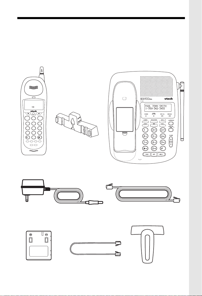
PARTS CHECKLIST
1. Handset
2. Base Unit
3. Wall Mounting Bracket
4. AC power Adaptor
5. Telephone Line Cords (x2)
6. Battery Pack
7. Belt Clip
AM
10:00
SIMON JAMES WILD
654532 465929115
NEW
LINE1 LINE2
00
LINE 1 LINE 2
OFF
ABC
DEF
2
1
3
GHI
MNO
JKL
5
4
6
TUV
PQRS
WXYZ
8
7
9
TONE
OPER
0
REDIAL/PAUSE
PROG
HOLD
FLASH
CONF
INTERCOM
WALL MOUNTING
BRACKET
HANDSET
To purchase replacement battery packs,
call VTECH Communications at 1-800595-9511. In Canada, call VTECH
Electronics at 1-800-267-7377.
MIC
BASE UNIT
AC POWER ADAPTOR
BATTERY PACK
TELEPHONE LINE CORDS
SHORT LINE CORD
BELT-CLIP
1
Page 2

IMPORTANT SAFETY INSTRUCTIONS
When using your telephone equipment, basic safety precautions should
always be followed to reduce the risk of fire, electric shock and injury to
persons, including the following:
1. Read and understand all instructions.
2. Follow all warnings and instructions marked on the product.
3. Unplug this product from the wall outlet before cleaning. Do not use liquid cleaners
or aerosol cleaners. Use a dry cloth for cleaning.
4. Do not use this product near water, for example, near a bath tub, wash bowl, kitchen
sink, or laundry tub, in a wet basement, or near a swimming pool.
5. Do not place this product on unstable cart, stand, or table. The telephone may fall,
causing serious damage to the telephone.
6. Slots and openings in the cabinet and the back or bottom are provided for ventilation,
to protect it from overheating, these openings must not be blocked or covered. The
openings should never be blocked by placing the product on the bed, sofa, rug, or
other similar surface. This product should never be placed near or over a radiator
or heat register. This product should not be placed in a built-in installation unless
proper ventilation is provided.
7. This product should be operated only from the type of power source indicated on the
marking label. If you are not sure of the type of power supply to your home, consult
your dealer or local power company.
8. Do not allow anything to rest on the power cord. Do not locate this product where the
cord will be abused by persons walking on it.
9. Do not overload wall outlets and extension cords as this can result in the risk of fire
or electric shock.
10.Never push objects of any kind into this product through cabinet slots as they may
touch dangerous voltage points or short out parts that could result in a risk of fire or
electric shock. Never spill liquid of any kind on the product.
11.To reduce the risk of electric shock, do not disassemble this product, but take it to
a qualified service personnel when some service or repair work is required. Opening
or removing covers may expose you to dangerous voltages or other risks. Incorrect
reassembly can cause electric shock when the appliance is subsequently used.
12. Unplug this product from the wall outlet and refer servicing to qualified service
personnel under the following conditions:
A. When the power supply cord plug is damaged or frayed.
B. If liquid has been spilled into the product.
C. If the product has been exposed to rain or water.
2
Page 3

IMPORTANT SAFETY INSTRUCTIONS
D. If the product does not operate normally by following the operating instructions. Adjust
only those controls, that are covered by the operating instructions because improper
adjustment of other controls may result in damage and will often require extensive
work by a qualified technician to restore the product to normal operation.
E. If the product has been dropped or the cabinet has been damaged.
F. If the product exhibits a distinct change in performance.
13. Do not use the telephone to report a gas leak in the vicinity of the leak.
CAUTION: TO REDUCE THE RISK OF FIRE OR INJURY, READ AND FOLLOW
THESE INSTRUCTIONS.
1. Use only the appropriate type andsize battery pack specified in the instruction
manual provided for this product.
2. Do not dispose of the battery pack in a fire. The cell may explode. Check with State
and local codes for possible special disposal instructions.
3. Do not open or mutilate the battery pack. Released electrolyte is corrosive and may
cause damage to the eyes or skin. It may be toxic if swallowed.
4. Exercise care in handling battery in order not to short the battery with conducting
materials such as rings, bracelets, and keys. The battery or conductor may overheat
and cause burns.
5. Charge the battery pack provided with or identified for use with this product only in
accordance with the instructions and limitations specified in the instruction manual.
6. Observe proper polarity orientation between the battery pack and battery charger.
SAVE THESE INSTRUCTIONS
3
Page 4
GETTING STARTED
DC IN 9V
LINE 2
+-
L1/L1+L2 L2
LINE 2
DC
SLIDE IN THE
BATTERY
COVER
PLACE THE NEW
BATTERY PACK
INTO THE
BA TTER Y
COMP AR TMENT
PLEASE NOTE THE
CORRECT POSITION
OF THE BATTER Y
P A CK WHEN
INST ALLING
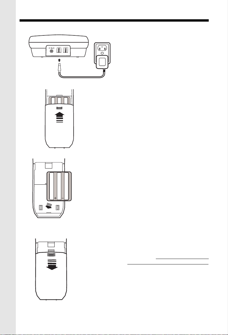
AC
OUTLET
• Plug the AC POWER ADAPTER into a
live electrical outlet and the DC POWER
CONNECTOR into the back of the Base
Unit.
• Slide the Handset battery cover down,
and remove it from the Handset
.
• Install the BATTERY PACK, with the
metal contacts facing down and aligned
with the Handset contacts. Replace
Handset battery cover.
PRESS and SLIDE
DOWNWARD
• Place the Handset into the Base Unit
cradle. Make sure the Charging light
is
illuminated. Charge for at least 16
hours before first using the phone.
The Handset can charge face up or
down.
4
Page 5
GETTING STARTED
RINGER LEVEL
L1
DIAL MODE
L2
L 2
TONE
PULSE
OFF
HIGH
OFF
HIGH
LOW
LOW
+-
L1/L1+L2 L2
TONE/PULSE SWITCH
LINE 2
DC
TELEPHONE
WALL JACK
WALL
BASE RINGER
SWITCH
DC IN 9V
DATA
DATA
TELEPHONE
WALL JACK
LINE 2
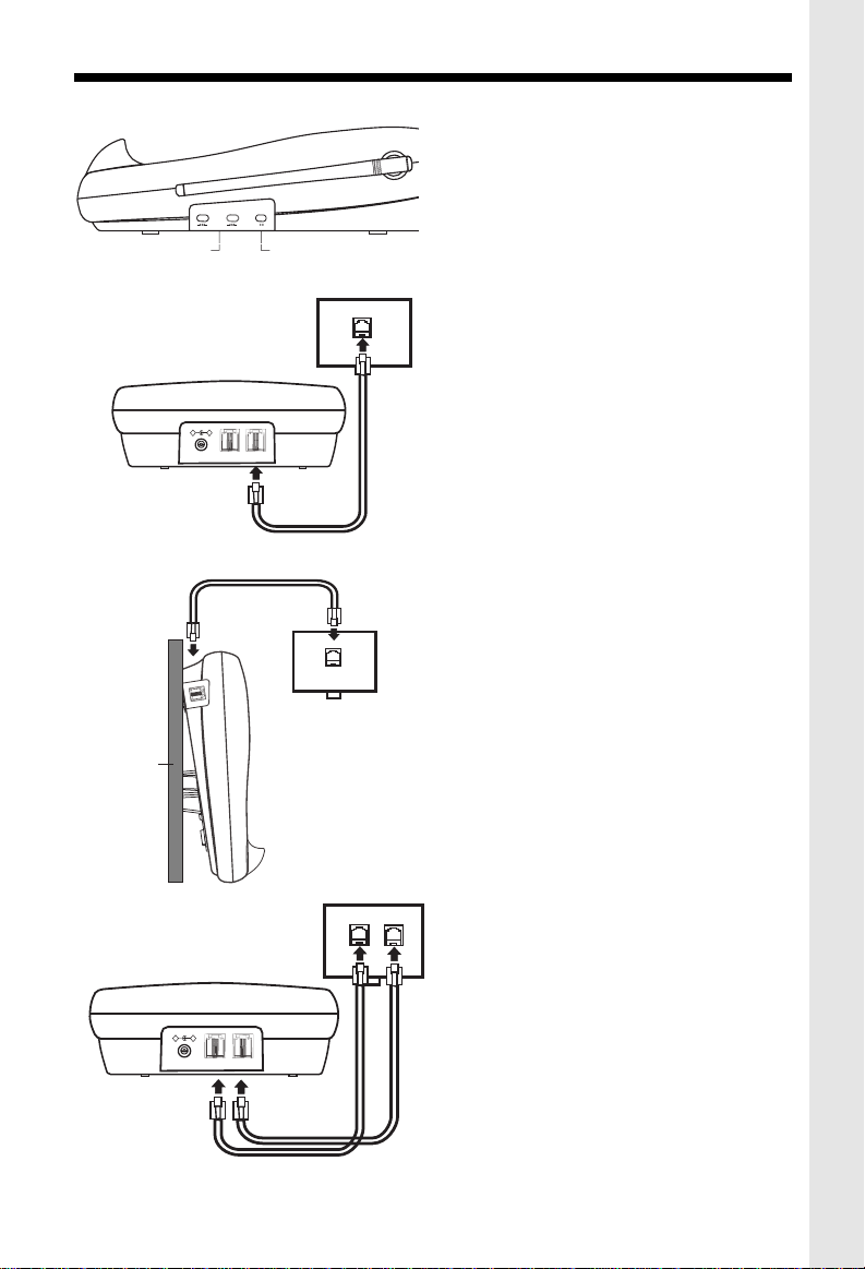
• Set the TONE/PULSE switch, located on
the antenna side of the Base Unit, to the
desired dialing mode. In most areas, TONE
is the desired mode.
• After charging the battery pack, connect
the telephone line(s)
1. If you have 2 lines coming out of
a single wall jack:
Connect a 4-wire (RJ-14) phone cord between the wall jack and the phone jack labeled L1 / L1+L2 .
If you are wall mounting your Base Unit, a
short, 4-wire phone is provided for your
convenience
TELEPHONE
WALL JACK
+-
DC IN 9V
L1/L1+L2 L2
LINE 2
2. If you have 2 lines, each coming
out of a separate wall jack:
Connect a phone cord from the wall jack
you wish to designate as your LINE1, to
the L1 / L1+L2 jack on the back of the
phone; next, connect a phone cord from
the remaining wall jack to the L2 jack on
the phone.
LINE 2
DC
NOTE: You can use your
VT2931
as a oneline phone, as well. For best results, raise
the antenna on the Handset and Base Unit
when using your telephone.
5
Page 6
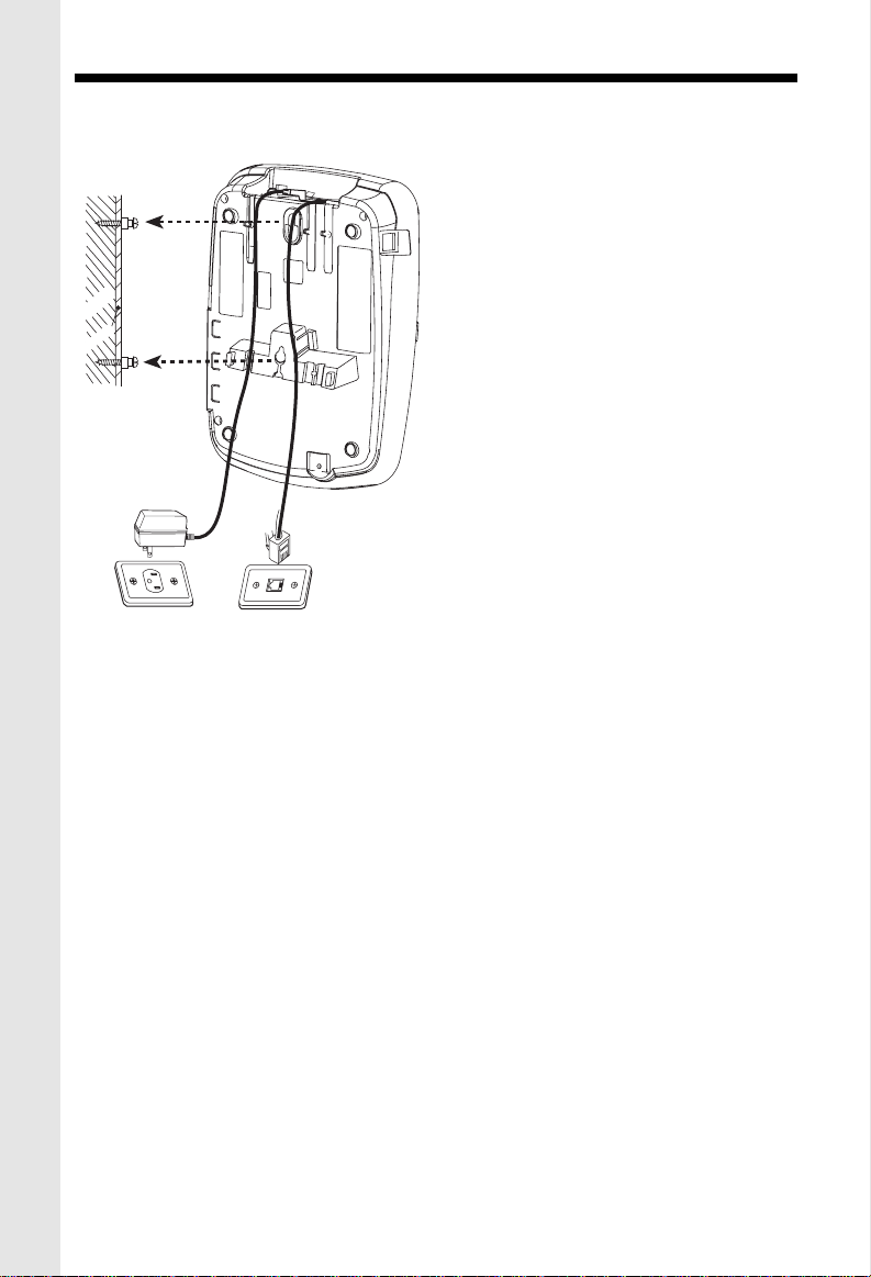
WALL MOUNTING
The Wall Mounting bracket is designed to fit on standard Wall Mounting plates
1.Choose a spot near an electrical
outlet and a telephone jack.
Your phone requires a modular telephone
jack and a standard electrical outlet (120v
AC). The power cord is six feet long; make
sure there is an electrical outlet within
reach of the Base Unit. The outlet should
wooden
stud
wallboard
4. Connect the telephone line cord(s).
Insert one end of the telephone line cord(s) into the appropriate jacks on the back of
the Base Unit, and the other end into the wall jack(s). For your convenience, a short
line cord is provided.
not be controlled by a wall switch. If the
switch is ever turned off, the phone will not
operate.
2. Position the wall mount bracket on
the base.
Line up the tabs on the wall mounting
bracket with the holes on the bottom of the
base. Snap the wall mounting bracket firmly
into place.
3. Mount the base on the wall.
Position the base so the mounting studs
will fit into the holes on the bottom of the
base. Position the power cord to extend
down the wall. Slide the base down on the
mounting studs until it locks into place.
5. Plug the AC adapter into an electrical outlet and the DC connector into the power jack
located on the back of the Base Unit.
6
Page 7
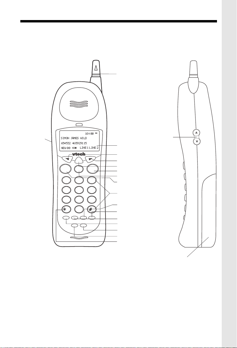
HANDSET UNIT KEY AND FEATURES
ANTENNA
HEADSET
JACK
SELECT
LINE 1 LINE 2
OFF
DEF
ABC
2
4
7
HOLD
1
GHI
PQRS
TONE
PROG
CONF
5
8
OPER
0
JKL
TUV
FLASH
INTERCOM
3
MNO
6
WXYZ
9
REDIAL/PAUSE
VOLUME UP & DOWN
DISPLAY
BACK KEY
FORWARD KEY
SELECT KEY
LINE 2 KEY
OFF KEY
LINE 1 KEY
DIALING KEYS (0-9)
FLASH KEY
REDIAL/PAUSE KEY
PROG KEY
HOLD KEY
INTERCOM KEY
CONF KEY
TONE KEY
(T empor ary T one)
BATTERY COMPARTMENT
7
Page 8
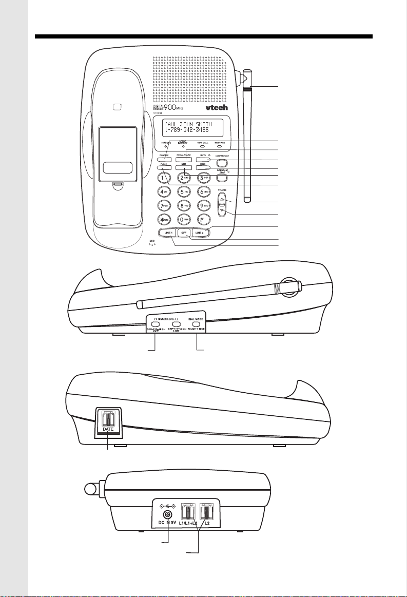
BASE UNIT KEYS AND FEATURES
ANTENNA
PGM/PRV KEY
REDIAL/PAUSE KEY
MUTE KEY
HOLD KEY
MEM KEY
FLASH KEY
VOLUME UP KEY
VOLUME DOWN KEY
LINE 2 KEY
OFF KEY
LINE 1 KEY
BASE RINGER
SWITCH
DATA PORT
AC POWER JACK
PHONE CORD JACK
L 2
TONE/PULSE SWITCH
LINE 2
LINE 2
DC
8
Page 9
BASIC TELEPHONE OPERATIONS
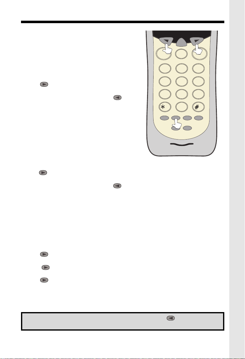
AREA CODE PROGRAMMING
To benefit from all the Caller ID features of your telephone, you must enter your home area code.
SELECT
If you live in an area where you dial calls within your
LINE 1 LINE 2
OFF
own area code by dialing 7 digits (no area code),
follow these steps (with the Handset OFF ):
• Press PROG.
• Press until AREA is blinking.
• Press SELECT.
• HOME should be blinking. If not, press until it
blinks.
• Press SELECT. ENTER AREA CODE is displayed.
• Enter your own home area code.
• Press SELECT.
1
4
7
HOLD
PQRS
ABC
JKL
TUV
OPER
FLASH
INTERCOM
DEF
3
MNO
6
WXYZ
9
REDIAL/PAUSE
2
GHI
5
8
TONE
0
PROG
CONF
LESS COMMON ALTERNATIVE
If you live in an area where all local calls require 10
digits (area code plus phone number, without dialing
“1” first:)
• Press PROG.
• Press until AREA is blinking.
• Press SELECT.
• HOME should be blinking. If not, press until it blinks.
• Press SELECT. ENTER AREA CODE is displayed.
• Enter 000.
• Press SELECT and continue below.
You may program up to 5 local area codes. An area code is “local” if you do not dial “1” when
you make calls to that area code. In other words, you make calls to “local” area codes by
dialing 10 digits (area code plus phone number) without a preceding “1”. This might include
your own area code
• Press PROG.
• Press until AREA is blinking.
• Press SELECT.
• Press until LOCAL is blinking.
Press SELECT.
• Press until the desired location is blinking (#1…..#5).
• Press SELECT . ENTER AREA CODE is displayed.
• Enter a “local” area code.
• Press SELECT.
• Press OFF when finished.
NOTE: To replace or edit an existing area code, use the key to delete the
existing digits, and enter the desired area code. Press SELECT when done.
9
Page 10
BASIC TELEPHONE OPERATIONS
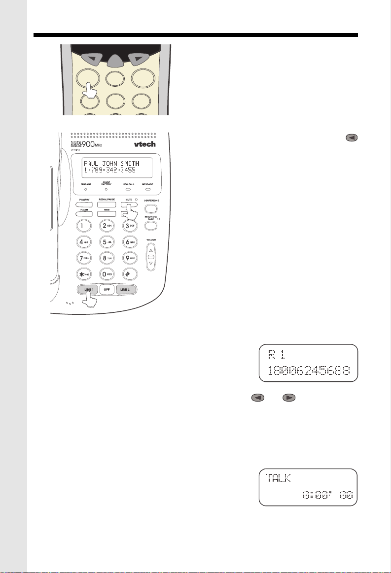
MAKING CALLS
SELECT
LINE 1 LINE 2
OFF
ABC
2
1
MIC
Handset:
listen for dial tone. Dial the phone number. The
Base Unit will display HANDSET IN USE, and
the corresponding LINE key will blink.Press OFF
DEF
3
to end your call.
Alternative Method
Dial the phone number, checking the display for
accuracy. If you make a mistake, use the
key to backspace. Once you have entered the
phone number, press the desired LINE key.
Press OFF to end your call.
Base Unit Speakerphone:
Press the desired LINE key and listen for dial
tone. Dial the phone number. The corresponding LINE key on the Handset will blink. Press
OFF to end your call.
SPEAKERPHONE TIPS
If you use your Speakerphone in a noisy environment, the other person’s voice may fade out.
In this case, try eliminating the environmental
noise (a television or radio playing, for example).
Otherwise, press MUTE while the other person
is speaking. Before you start to talk, press MUTE
again so the other person can hear you.
Press desired LINE key and
REDIAL/PAUSE
From the Handset: Your VT2931 Handset remembers the
last 5 phone number you dialed. With the Handset off, press
REDIAL/PAUSE. The Handset will display:
This is the last phone number dialed from the Handset. Press or to scroll through
the previous numbers dialed. Once the desired number is displayed on the Handset, press
the appropriate LINE key to dial.
From the Base Unit: Press REDIAL/PAUSE. The last number dialed from the Base Unit is
displayed. Press the appropriate LINE key to dial.
ANSWERING CALLS
Handset:
glow steadily and the Handset will display:
The Base Unit will display
sponding LlNE key will blink.
Press
Press the flashing LINE key . The LINE key will
OFF
to end your call
HANDSET IN USE,
.
and the corre-
10
Page 11

BASIC TELEPHONE OPERATIONS
9
7
8
Speakerphone
: Press the flashing LINE key. The LINE
key will glow steadily and the Base Unit will display:
The corresponding LINE key on the Handset will blink while the Speakerphone is in use.
Press OFF to end your call.
LINE IN USE (Parallel Set Detection)
If a different telephone device, sharing the same line(s) as your VT 2931, is in use, the
corresponding LINE key(s) will blink on the Handset and Base Unit, indicating activity on
that line.
HANDSET VOLUME
Adjust the Handset volume with the and keys, located
on the side of the Handset.
VOLUME KEYS
The Handset will display the relative volume level as you
adjust it.
SPEAKERPHONE VOLUME
Adjust the Base Unit volume with the and keys,
located to the right of the dialpad. The Base will display the
relative volume level as you adjust it. The Speakerphone
volume can only be adjusted while the Base Unit is IN USE
(in Speakerphone or Intercom mode).
CALL TIMER
While the Handset or Base is on a call, the corresponding display will show the approximate
duration of that call. This is very helpful in monitoring long distance expenses.
HOLD
To place a call on hold, press HOLD on the Handset or Base, whichever you are using.
HOLD will be displayed on the corresponding screen.
To return to your call, press the appropriate LINE key.
CALL WAITING
If you subscribe to Call Waiting, you will hear a tone while on the phone as you receive a
second call. If you subscribe to Caller ID on Call Waiting, the Handset (or Base) will display
who the second caller is before you answer.
TONE
OPER
0
REDIAL/PAUSE
PROG
HOLD
FLASH
CONF
INTERCOM
To answer Call Waiting, press FLASH. To return to your original call,
press FLASH again. This procedure is the same for Handset and
Speakerphone calls.
PAGING THE HANDSET
• To make the Handset ring, press INTERCOM/PAGE on the Base.
• To stop the ringing, press OFF on the Handset, or Base Unit.
11
ADVANCED OPERATION
Page 12
BASIC TELEPHONE OPERATIONS
6
5
4
GHI
JKL
MNO
9
7
8
PQRS
TUV
PROG
CONF
HOLD
INTERCOM
FLASH
REDIAL/PAUSE
WXYZ
0
TONE
OPER
1
2
3
ABC
DEF
OFF
LINE 1 LINE 2
SELECT
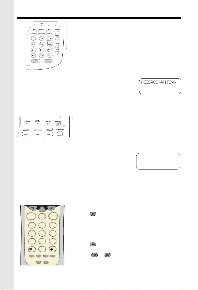
INTERCOM
(Conversation between the Base and Handset)
From the Handset:
ring, and the intercom call will be
Press INTERCOM. The Base Unit will
automatically
connected.
From the Base:
Press INTERCOM/PAGE. The Handset will
ring. To answer the call, press INTERCOM on the Handset.
To end an Intercom call, press OFF on either the Handset or
MIC
the Base.
VOICE MAIL INDICATOR
If you subscribe to Voice Mail, the MESSAGE light on the Base
Unit will flash when you have new messages. The Handset will
display:
Once you have reviewed your new messages, the MESSAGE WAITING indication on the
Handset, and the MESSAGE light on the Base will turn off.
VOICE MAIL TIPS:
After hearing your messages, wait until the Voice Mail
indicators turn off before you make another call. This will
ensure the indicators do not remain on after the messages are reviewed.
If, after reviewing all new voice messages, the Handset or Base Unit Voice Mail indicator
remains on, using the Handset, follow these steps:
• Press PROG.
• Press #. The Handset displays:
• With LIGHT-OFF flashing, press SELECT.
If you have new messages, but the Voice Mail indicators do not turn on, ask your phone
company to make sure your Voice Mail service has Visual Message Indication assigned.
IMPORTANT: If you move or change to a different telephone service provider, you should
reset your Visual Message waiting feature:
MESSAGE WAITING
LIGHT-OFF RESET
1. Press PROG on the Handset
2. Press #
3. Press so that RESET is blinking
4. Press SELECT.
SETTING THE HANDSET RINGER
• Press PROG.
• Press until RINGER is blinking
• Press SELECT.
• Press or to select LINE1 or LINE2.
• Press SELECT.
12
Page 13
BASIC TELEPHONE OPERATIONS
L 2
There are 4 ringer styles. The current setting is displayed.
• Press or to hear the other ring styles OR turn the Handset ringer OFF.
• When the desired ringer type is blinking, press SELECT.
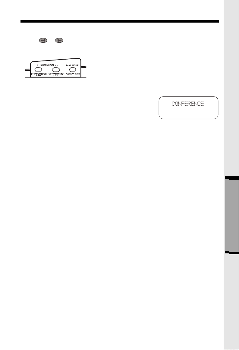
BASE UNIT RINGER
The Base Unit ringer volume is controlled by a switches
on the right edge of the Base Each line can be set to Off,
Low, or High volume.
CONFERENCE CALLING
To talk to both lines at the same time:
1. While you are one line, press HOLD.
2. Make or receive a call on the avaiable line.
3. Press CONF. You are now talking to both lines.
4. To end your conference call, press OFF.
The procedure is the same for the Handset and Base. Whichever you are using,CONFERENCE
is displayed on the screen.
To place both lines on hold, press HOLD. Press CONF to return to the conference call. To
switch from Handset to Base ( or vice versa), press HOLD on whichever component you’re
using, then CONF on the other.
NOTE: Both the Handset and Base can join in the Conference call.
ADVANCED OPERA-
13
Page 14

CALLER ID
This telephone provides two types of Caller ID:
Caller ID:
(requires Caller ID service from your telephone company).
Displays the name and number of each caller after the phone begins ringing
Caller ID on Call Waiting:
you hear the Call Waiting tone (requires Caller ID on Call Waiting service).
The phone has a Call Log, which stores the name, number, date, and time of the last
20 calls received. You can review the Call Log to see who called while you were out. You
can speed-dial numbers from the Call Log. And you can store names and numbers from
the Call Log into your directory.
Shows the name and number of each caller on Call Waiting after
REVIEWING THE CALL LOG
With the Handset OFF:
• Press or . You will see the number of NEW (not viewed) and OLD (previously
viewed) calls.
• Continue to press or to review the callers.
Some locations are not equipped to send Caller ID information when a person places a call.
When you receive calls from such locations, your phone will display UNAVAILABLE.
If a caller purposely blocks their phone number from being delivered by Caller ID, your phone
will display PRIVATE.
HINT: If a follows the phone number (x3 for example) it
indicates the party has called more than once.
ERASING CALLS
To erase a call; with the Handset OFF:
• Press or until you see the call you want to erase.
• Press SELECT.
• Press until ERASE is blinking. Press SELECT.
• Press until YES is blinking.Then press SELECT.
To erase your entire Call Log; after you have viewed all calls and the handset is off:
• Press or until you see any call in the log.
• Press SELECT.
• Press until ERASE is blinking. Press SELECT.
• Press until ALL is blinking.Then press SELECT .The
handset displays:
• Press until YES is blinking.Then press SELECT.
SPEED DIALING FROM CALLER ID
With the Handset OFF:
• Press or until you see the desired caller.
• Press the desired line key. You will hear a dial tone, and the number will be dialed automati-
cally.
14
Page 15

DIRECTORY
TO STORE A NAME AND NUMBER
• Press PROG. DIRECTORY will be blinking.
• Press SELECT.
• The screen will display ENTER NAME.
Use the Dialing keys to enter the desired name. Press the key until the desired letter or
character appears. A guide to the characters:
KEY CHARACTERS
1 1
2 A>B>C>2
3 D>E>F>3
4 G>H>I>4
5 J>K>L>5
6 M>N>O>6
7 P>Q>R>S>7
8 T>U>V>8
9 W>X>Y>Z>9
0 0
* *
# & ’ , - . #
If consecutive characters are found on the same key (D and E, for example), you’ll need to
press to advance to the next space. For example, to enter the name DEAN:
Press 3 (
Press
Press 3
Press 2(
Press 6
twice
twice
D
)
(E)
A
)
(N)
When the name is complete, press SELECT. The
screen will display:
Enter the phone number. Press REDIAL/PAUSE if you need to enter a 2-second pause
in the dialing sequence. (For example, you might store a voice mail access number, pause,
password.)
When the phone number is complete, press SELECT .
STORING A CALLER ID RECORD IN THE DIRECTOR Y
With the Handset OFF:
• Press or until you see the desired call.
• Press SELECT .
• Press until PGM is blinking.
• Press SELECT .
If you want to edit the name, press to erase
letters. Use the dialpad to enter new letters. When
15
Page 16

DIRECTORY
DIAL
EDIT
ERASE
12345678
the name is correct, press SELECT.
If you want to edit the number, press to erase digits. Use the dialpad to enter new digits.
When the number is correct, press SELECT.
You will then hear a long beep. The name and number have been stored in the Directory.
MAKING DIRECTORY CALLS
• Press SELECT. DIRECTORY will appear.
• Press or to scroll to the desired name; or,
• Search by entering the first letter of the name, and then
press or if necessary.
• Press the desired LINE key. You will hear a dial tone, and
the number will be dialed.
EDITING A DIRECTORY ENTRY
• Press SELECT . The Handset says DIRECTORY.
• Press or to scroll to the desired name; or,
• Search by entering the first letter of the name, and then
press or if necessary.
• Press SELECT .
• Press until EDIT is blinking.
• Press SELECT .The name appears.
• If you want to edit the name, press to erase letters. Use the dialpad to enter new
letters. When the name is correct, press SELECT.
• The number appears. If you want to edit the number, press to erase digits. Use the
dialpad to enter new digits. When the number is correct, press SELECT.
ERASING A DIRECTORY ENTRY
• Press SELECT.
• Press or to scroll to the desired name; or,
• Search by entering the first letter of the name, and then press or if necessary.
• Press SELECT .
• Press until ERASE is blinking.
• Press SELECT. Press until
• Press SELECT.
YES
is blinking.
CHARGING: illuminates when the Handset is
cradled.
SPARE BATTERY: illuminates when a battery
Pack is charging in the Base Unit charger.
NEW CALL: flashes when new Caller ID records
have been received.
MESSAGE: flashes when new Voice Mail mes-
sages are present.
16
Page 17

BASE UNIT OPERATION
ANSWERING CALLS
• Press LINE 1 or 2.
• Press OFF again to end your call.
DIALING
• Press LINE 1 or 2. Dial the phone number.
Adjust the Base Unit volume to a comfortable
level.
• Press OFF to end your call.
SPEED DIALING
• Press LINE 1 OR 2.
• Press MEM. Enter Location (0-9).
MIC
PROGRAMMING SPEED DIAL NUMBERS
• Press PROG. The Base will display: PROGRAM.
• Press MEM. The Base will display : ENTER 0 TO 9
• Enter desired Location (0-9).The Base will display: ENTER NAME
• Use the Base dial pad to enter the letters (16 characters maximum).
The following table lists the characters found on each key:
• Press OFF to end your call.
KEY CHARACTER
1 1
2 A>B>C>2
3 D>E>F>3
etc.
(For the complete table, see: DIRECTORY - TO STORE A NAME AND NUMBER).
To enter 2 characters located on the same key, or, to add a space, use the
VOLUME
For example, to enter the name 'DEAN':
• Press 3
• Press VOLUME
• Press 3 twice
• Press 2
• Press 6 twice
• Press PROG when you finish entering the name. The Base will display : ENTER NUMBER.
• Enter the telephone number you wish to store (32 digits maximum).
• Press PROG. You will hear a confirmation beep, and the screen will go blank.
key.
17
Page 18

BASE UNIT OPERATION
STORING A PAUSE IN A DIALING SEQUENCE
To insert a pause while programming a speed dial number, press REDIAL/PAUSE at the
appropriate point in the number sequence. This inserts a 2 second pause. A “P” appears in
the display representing the pause. For longer pauses, press REDIAL/PAUSE two or more
times. Each pause is treated as a stored digit.
INTERCOM
You can Intercom the Handset from the Base Unit (or vice versa).
Press INTERCOM/PAGE on the Base Unit. The Base Unit and Handset will display
**
PAGING
On the Handset, press INT.COM to respond to the page, or press OFF to terminate the page.
When the Handset initiates the page, the Base Unit will ring
Both Handset and Base display INTERCOM while in active Intercom mode.
Press INTERCOM/PAGE on the Base Unit to terminate Intercom mode.
CALL WAITING CALLER ID (CID)
In the OFF (on-hook) mode, the Base Unit will display
**.
twice
CALLER ID
, and enter Intercom mode.
data as the call comes in.
In the SPEAKERPHONE (off-hook) mode, the Base Unit will display
CALLER ID
A
NEW CALL
caller ID records have been reviewed on the Handset, the NEW CALL light will go out.
NOTE: Caller ID and Call Waiting Caller ID are subscription services, available through
Due to regional incompatibilities, Caller ID information may not be available for every call you
receive. In addition, the calling party may intentionally block their name and phone number
from being sent.
.
light will flash on the Base Unit to alert you to new CID records. Once the new
most local phone service providers. You must subscribe to these services to
benefit from the Caller ID features of this phone. Contact your local phone company
for details.
CALL WAITING
DATA PORT
Your
VT2931
edge of the Base Unit. This port provides an easy
way to connect your fax machine, laptop computer, modem, or other telephone device for direct
acces to
The Data Port only provides access to Line 2, so
DATA PORT
NOTE: While the Data Port is in use, accidental use of Line 2 by a parallel phone, the
Handset, or a Call Waiting ID alert may in inerrupt the data transmission.
you must have an active line connected to the
LINE2
Connect an RJ-11(2-element) phone cord from
the Data Port to you fax, laptop,etc.
has a Data Port on the left-hand
LINE2.
input on the back of the
VT2931.
VT2931
18
Page 19

ADDITONAL OPERATIONS
POWER BACKUP
When a spare battery pack (optional) is installed
in the Base Unit, your VTech cordless telephone
uses this battery to provide operational backup
during a power failure. If you have a fully charged
battery pack in the Base Unit charger, you will be
able to place and receive calls from the Handset
for up to 5 hours.
Note:
During power backup mode, the Base Unit functions are not operable, In addition, Caller ID
information may not be reliable.
REPLACING A DRAINED HANDSET BATTERY
The spare battery pack can also be used to replace a drained Handset battery, to ensure
uninterrupted use. Be sure to put the drained battery pack in the Base Unit charger for
recharging.
The Base Unit battery compartment charges at a slower rate than a battery pack charging in
the Handset. It takes 24 hours to fully charge a battery pack in the Base Unit.
To purchase replacement battery packs, call
VTECH Communications at 1-800-595-9511.
In Canada, call
VTECH Electronics at 1-800-267-7377.
ADDITIONAL INFORMATION
19
Page 20

HEADSET OPERATIONS
Your VTech cordless phone is equipped with a 2.5mm headset Jack for use with an optional
accessory Headset for hands-free operation.
If you choose to use the Headset option, you must obtain an optional accessory Headset,
which is compatible with the VTech cordless phone.
To purchase a Headset, call VTech Customer Service at 1-800-595-9511.
In Canada, call VTECH Electronics at 1-800-267-7377.
Once you have a compatible 2.5mm Headset, locate the Headset Jack on the VTech cordless
phone Handset. Connect the plug on the Headset cord to the jack on the cordless Handset.
The plug should fit securely. Do not force the connection.
OPERATION
NOTE: Whenever a compatible Headset is con-
nected to the cordless Handset, the microphone on
the Handset will be muted. This is done to limit the
effect of background noise.
The following operational characteristics also apply
to other headsets which are not sold by VTech;
LINE 1 LINE 2
OFF
ABC
2
1
GHI
JKL
5
4
TUV
PQRS
8
7
TONE
OPER
0
PROG
HOLD
FLASH
CONF
INTERCOM
REDIAL/PAUSE
DEF
3
MNO
6
WXYZ
9
however, VTech assumes no responsibility for their
performance.
The VTech compatible Headset has a reversible,
monaural design. You can wear you Headset on either ear, leaving one ear free for room conversation.
The headband can be adjusted to fit the contour of
you head. Using both hands, slide the headband up
or down so that it rests comfortably on your head,
with the speaker cushion centered against your ear.
For maximum sound quality, the flexible microphone
should be positioned at the corner of your mouth,
about one inch from your face.
BELT CLIP
The VTech cordless phone is also equipped with a
detachable belt clip. Align the pins on the inside edge
of the clip with the notches on the sides of the VTech
cordless phone Handset. The belt clip should snap
securely into place.Do not force the connection.
20
Page 21

MAINTENANCE
Your VT1932 cordless telephone contains sophisticated electronic parts, so it must be
treated with care.
Avoid rough treatment
Please the Handset down gently. Save the original packing materials to protect your telephone if you ever need to ship it.
Avoid water
Your telephone can be damaged if it gets wet. Do not use the Handset outdoors in the rain, or
handle it with wet hands. Do not install your Base Unit near a sink, bathtub or shower.
Electrical storms
Electrical storms can sometimes cause power surges harmful to electronic equipment.
For your own safety, use caution when using electric appliances during storms.
Cleaning your telephone
Your telephone has a durable plastic casing that should retain its iuster for many
years. Clean it only with a soft cloth slightiy dampened with water or a mild soap. Do not use
excess water or cleaning solvents of any kind.
Remember that electrical appliances can cause serious injury if used when you are wet or
standing in water. If your Base Unit should fall into water, DO NOT RETRIEVE IT UNTIL YOU
UNPLUG THE POWER CORD AND TELEPHONE LINE CORDS FROM THE WALL. Then
pull the unit out by the unplugged cords. If you have difficulty operating your phone, the
suggestions below should solve the problem. If you still have difficulty after trying these
suggestions, call VTECH Communications at 1-800-595-9511. In Canada, call VTECH Electronics at 1-800-267-7377.
21
ADDITIONAL INFORMATION
Page 22

IN CASE OF DIFFICULTY
THE PHONE DOESN'T WORK AT ALL.
• Make sure the Power Cord is pugged in.
• Make sure the telephone line cords are plugged firmly into the base unit and the
telephone wall jack.
• Make sure the batteries are properly charged. If the 'LOW BATTERY' message is
shown, the battery pack needs charging.
NO DIAL TONE.
• First check all the suggestions above.
• If you still don't hear a dial tone, disconnect the base unit from the telephone jack and
connect a different phone. If there is no dial tone on that phone either, the problem
is in your wiring or local service. Call your local telephone company.
YOU GET NOISE, STATIC, OR A WEAK SIGNAL EVEN WHEN YOU'RE NEAR
THE BASE UNIT.
• Household appliances plugged into the same circuit as the base unit can sometimes
cause interference. Try moving the appliance or the base unit to another outlet.
YOU GET NOISE, STATIC, OR A WEAK SIGNAL WHEN YOU'RE AWAY FROM
THE BASE UNIT.
• You may be out of range. Either move close to the base, or relocate the base unit.
• The layout of your home may be limiting the range. Try moving the base unit to another
position.
THE HANDSET DOES NOT RING WHEN YOU RECEIVE A CALL.
• Make sure you have the handset ringer activated. To set the ringer, see "SETTING
THE HANDSET RINGER".
• Make sure the telephone line cord is plugged firmly into the base unit and the telephone
jack. Make sure the power cord is plugged in.
• You may be too far from the base unit.
• You may have too many extension phones on your telephone line to allow all of them
to ring. Try unplugging some of the other phones.
YOU HEAR OTHER CALLS WHILE USING YOUR PHONE.
• Disconnect your base unit from the telephone jack, and plug in a regular telephone.
If you still hear other calls, the problem is probably in your wiring or local service. Call
your local telephone company.
22
Page 23

IN CASE OF DIFFICULTY
YOU HEAR NOISE IN THE HANDSET, AND NONE OF THE KEYS OR
BUTTONS WORK.
Make sure the power cord is plugged in.
COMMON CURE FOR ELECTRONIC EQUIPMENT
Electronics, like people, can sometimes get confused. If the unit does not seem to be
responding normally, then try putting the handset in the cradle. If it does not seem to
respond after trying this a few times, do the following (in the order listed):
1. Disconnect the power to the base.
2. Disconnect (remove) the handset battery pack.
3. Remove the base unit battery pack, where applicable.
4. Wait a few minutes.
5. Connect power to the base.
6. Install the handset battery pack.
7. Install the base unit battery pack, where applicable.
8. Place the handset in the base unit cradle. If the handset has not been recently
charged, allow 8 hours before use.
23
ADDITIONAL INFORMATION
Page 24

WARRANTY STATEMENT
WHAT DOES OUR WARRANTY COVER?
• Any defect in material or workmanship.
FOR HOW LONG AFTER THE ORIGINAL PURCHASE?
• To the original purchaser only - ONE YEAR.
WHAT WILL VTECH DO?
• At our option, repair or replace your unit.
HOW DO I SEND MY UNIT, IN OR OUT OF WARRANTY?
• Call VTECH Communications customer service for Return Authorization at:
in Canada, call VTECH Electronics at:
• Properly pack your unit. lnclude any cables & accessories which were originally
provided with the product. We recommend using the original carton and packing
materials.
• Include in the package a copy of the sales receipt or other evidence of date of original
purchase (if the unit was purchased within the lase twelve months).
• Print your name and address, along with a description of the defect, and include this
in the package.
• Include payment for any service or repair not covered by warranty, as determined by
VTECH Communications.
• Ship the unit via UPS Insured, or equivalent to:
In Canada, ship the unit via UPS Insured, or equivalent to:
VTECH Communications assumes no responsibility for units sent without prior
1-800-595-9511
1-800-267-7377.
VTECH COMMUNICATIONS
11035 SW 11th St.
Bldg . B Suite 270
BEAVERTON, OREGON 97005
VTECH ELECTRONICS
Suite 200- 7671 Alderbridge Way
Richmond, B.C. V6X 1Z9
Return Authorizatlon
.
WHAT DOES OUR WARRANTY NOT COVER?
• Batteries
• Damage from misuse, neglect, or acts of nature(lightning,floods,powersurges,etc.)
• Products which may have been modified or incorporated into other products.
• Products purchased and/or operated outside the USA, its territories, or Canada.
• Products ser viced by the owner or a service facility not expressly authorized by VTECH
Communications.
• Products purchased more than 12 months form current date.
• Units purchased in "AS IS" condition, or units purchased as "Distressed Merchandise".
HOW DOES STATE LAW OR PROVINCE LAW RELATE TO THIS WARRANTY?
• This warranty gives you specific rights. You may also have other rights which vary
from state to state or from province to province.
24
Page 25

FCC AND IC REGULATIONS
This equipment complies with Parts 15 and 68 of the Federal Communications
Commission (FCC) rules for the United States. It also complies with regulations RSS210
and CS-03 of Industry and Science Canada. Operation is subject to the following two
conditions: (1) this device may not cause interference, and (2) this device must accept
any interference, including interference that may cause undesired operation of the device.
A label is located on the underside of the base unit containing either the FCC registration
number and Ringer Equivalence Number (REN) or the IC registration number and Load
Number. You must, upon request, provide this information to your local telephone
company.
This equipment is compatible with inductively coupled hearing aids.
Should you experience trouble with this telephone equipment, please contact:
VTECH COMMUNICATIONS
SERVICE DEPT. at 1-800-595-9511.
In Canada, call VTECH Electronics at 1-800-267-7377.
For repair/warranty information. The telephone company may ask you to disconnect this
equipment from the line network until the problem has been corrected.
FCC Part 15
Warning: Changes or modifications to this unit not expressly approved by the party
responsible for compliances could void the user's authority to operate the equipment.
The equipment has been tested and found to comply with part 15 of the FCC rules. These
limits are designed to provide reasonable protection against harmful interference in a
residential installation. This equipment generates, uses and can radiate radio frequency
energy and, if not installed and used in accordance with the instructions, may cause
harmful interference to radio communications. However, there is no guarantee that
interference will not occur in a particular installation. If this equipment does cause harmful
interference to radio or television reception, which can be determined by turning the
equipment off and on, the user is encouraged to try and correct the interference by one
or more of the following measures:
• Reorient or relocate the receiving antenna.
• Increase the separation between the equipment and receiver.
• Connect the equipment into an outlet or on a circuit different from that to which the
receiver is connected.
• Consult the dealer or an experienced radio/TV technician for help.
FCC Part 68
The FCC requires that you connect your cordless telephone to the nationwide telephone
network through a modular telephone jack (USOC RJ11C, RJ11W or RJ14).
Your telephone company may discontinue your service if your equipment causes harm
to the telephone network. They will notify you in advance of disconnection, if possible.
During notification, you will be informed of your right to file a complaint with the FCC.
Occasionally, your telephone company may make changes in its facilities, equipment,
25
Page 26

FCC AND IC REGULATIONS
operation, or procedures that could affect the operation of your equipment. If so, you will
be given advance notice of the change to give you an opportunity to maintain uninterrupted
service.
The base unit contains no user serviceable parts. The handset contains a user
replaceable battery pack.
If it is determined that your telephone equipment is malfunctioning, the FCC requires that
it not be used and that it be unplugged from the modular jack until the problem has been
corrected. Repairs to this telephone equipment can only be made by the manufacturer
or its authorized agents or by others who may be authorized by the FCC. For repair
procedures, follow the instructions outlined under the manufacturer’s Limited Warranty.
This equipment may not be used on coin service provided by the phone company or Party
Lines.
The REN is useful in determining the number of devices you may connect to your
telephone line and still enable the devices to ring when you receive a call. The general
rule is that the REN value should not exceed 5.0 total; however, contact your local
telephone company for the specific number in your area.
IC (Industry Canada)
This telephone is registered for use in Canada.
Notice: The REN assigned to this device denotes the number of devices you may
Notice: The Industry Canada label identifies certified equipment. This certification means
Before installing this equipment, users should ensure that it is permissible to be connected
to the facilities of the local telecommunications company. The equipment must also be
installed using an acceptable method of connection. The customer should be aware that
compliance with the above conditions may not prevent degradation of services in some
situations.
Repairs to certified equipment should be made by an authorized Canadian maintenance
facility designated by the supplier. Any repairs or alterations made by the user to this
equipment, or equipment malfunctions, may give the telecommunications company cause
to request the user to disconnect the equipment.
Users should ensure for their own protection that the electrical ground connections of the
power utility, telephone lines and internal metallic water pipe system, if present, are
connected together. This precaution may be particularly important in rural areas.
Caution: Users should not attempt to make such connections themselves, but shoul
connect to the telephone loop, which is used by the device to prevent overloading,
The termination on a loop may consist of any combination of devices subjected
only to the requirement that the sum of the REN does not exceed five (5.0)
that the equipment meets certain telecommunications network protective,
operational and safety requirements. The Department does not guarantee the
equipment will operate to the user's satisfaction.
contact the appropriate electrical inspection authority, or electrician, as
appropriate.
26
Page 27

FCC AND IC REGULATIONS
Your VT 2931 is designed to operate at the maximum power allowed by the FCC . This
means your handset and base unit can communicate only over a certain distance - which
will depend on the location of the base unit and handset, weather, and the construction
and layout of your home or office.
THE RBRC SEAL
TM
The RBRC Seal on the nickel-cadmium battery
R
contained in our product indicates that VTech
Communications, Inc. is voluntarily participating in an
industry program to collect and recycle these batteries at
the end of their useful lives, when taken out of service
within the United States and Canada.
The RBRC program provides a convenient alternative to placing used nickel-
R
cadmium batteries into the trash or municipal waste, which may be illegal in your
area.
VTech’s participation in RBRC makes it easy for you to drop off the spent battery
at local retailers participating in the RBRC program or at authorized VTech
R
R
product service centers. Please call 1-800-8-BATTERYTM for information on NiCd battery recycling and disposal bans/restrictions in your area. VTech’s involvement
in this program is part of its commitment to protecting our environment and conserving
natural resources.
Remove the nickel-cadmium battery pack by pressing on the Handset battery cover
and sliding downward.
RBRC is a registered trademark of Rechargeable Battery Recycling
R
Corporation.
27
Page 28

TECHNICAL SPECIFICATIONS
FREQUENCY CONTROL
Crystal Controlled Dual PLL Synthesizer
TRANSMIT FREQUENCY
Handset : 923.10 MHz to 927.75 MHz ( All ten channels within this range)
Base : 902.3 MHz to 906.65 MHz (All ten channels within this range)
RECEIVE FREQUENCY
Handset : 902.3 MHz to 906.65 MHz ( All ten channels within this range)
Base : 923.10 MHz to 927.75MHz ( All ten channels within this range)
NOMINAL EFFECTIVE RANGE
Maximum power allowed by FCC and IC. Actual operating range may vary according to
environmental conditions at the time of use.
SIZE
Handset : 17.5 x 6 x 4.5cm (L x W xT)
Base : 20.5 x 17x 70cm (L x W x T) Maximum (Antenna excluded)
WEIGHT
Handset : 205 grams
Base : 570 grams
POWER REQUIREMENTS
Handset : Self-contained nickel-cadmium rechargeable battery supply, 3.6V nominal,
Maximum (Antenna excluded)
600mAh capacity.
Base : 9VDC @ 500mA
MEMORY
Speed Dial: 50 Memory locations, 32 digits and 16 letters per location.
CID : Alpha Numeric Display 50 Memory locations
SPECIFICATIONS ARE TYPICAL AND MAY CHANGE WITHOUT NOTICE.
28
Page 29

TABLE OF CONTENTS
PARTS CHECK LIST...............................................................................................................1
IMPORTANT SAFETY INSTRUCTIONS...............................................................................5
GETTING STARTED..............................................................................................................7
WALL MOUNTING.................................................................................................................9
HANDSET UNIT KEYS AND FEATURE..............................................................................10
BASE UNIT KEYS AND FEATURES...................................................................................11
BASIC TELEPHONE OPERATIONS
Area Code Programming.....................................................................................................12
Making Calls..........................................................................................................................12
Speakerphone Tips...............................................................................................................12
Redial/Pause................................................................................................................... ......13
Answering Calls....................................................................................................................13
Handset Volume ....................................................................................................................13
Mute.......................................................................................................................................13
Hold........................................................................................................................... ............13
Call Waiting............................................................................................................................13
Paging the Handset...............................................................................................................14
Intercom................................................................................................................................14
Voice Mail Indicator................................................................................................................14
Voice Mail Tips.......................................................................................................................14
Setting The Handset Ringer..................................................................................................14
Handset Ringer Volume.........................................................................................................15
Base Unit Ringer...................................................................................................................15
Handset Speakerphone Feature..........................................................................................15
CALLER ID
Reviewing the Call Log..........................................................................................................16
Erasing Calls.........................................................................................................................16
Speed Dialing from Caller ID.................................................................................................16
DIRECTORY
To Store a Name And Number.............................................................................................17
Storing a Caller ID Record in the Directory...........................................................................17
Making Directory Calls..........................................................................................................17
Editing a Directory Entry........................................................................................................18
Erasing a Directory Entry......................................................................................................18
BASE UNIT OPERATION
Answering Calls.....................................................................................................................18
Dialing ...................................................................................................................................18
Speed Dialing.........................................................................................................................19
Programming Speed Dial Numbers.......................................................................................19
Storing A Pause In A Dialing Sequence................................................................................19
Intercom................................................................................................................................19
Call Waiting Caller ID ( CID )..................................................................................................19
Message Indicator.................................................................................................................20
ADDITIONAL OPERATIONS...............................................................................................20
HEADSET OPERATIONS......................................................................................................21
MAINTENANCE....................................................................................................................22
IN CASE OF DIFFICULTY....................................................................................................22
WARRANTY STATEMENT...................................................................................................24
FCC AND IC REGULATIONS ...............................................................................................2
THE RBRC SEAL .................................................................................................................8
TECHNICAL SPECIFICATIONS...........................................................................................25
R
29
Page 30

VTECH TELECOMMUNICATIONS LTD.
A member of THE VTECH GROUP OF COMPANIES.
Distributed in the U.S.A. by VTech Communications Inc, Beaverton, Oregon, 97008
Distributed in the Canada by VTech Electronics Canada Ltd., Suite 200-7671 Alderbridge
Way Richmond, B.C. V6X 1Z9.
Copyright 2000 for VTECH TELECOMMUNICATIONS LTD.
Printed in China
91-xxxx-10-00
ISSUED 0
30
 Loading...