

Page 1
900
MHz
1
!
DlGlTA L
CORDLESS
SPREAD
HONE
SPECTRUM
MODEL VT 1'980/ VT.1981
VTECH COMMUNICATIONS LTD.
Distributed in the U.S.A. by VTECH Communications,8770 SW Nimbus Avenue/
Beaverton, Oregon, 97008
distributed in Canada by VTECH Electronics Canada Ltd., 200-7671 Alderbridge Way,
Ricmond,B.C., V6XlZ9
copyright 1997 for
VTECH COMMUNICATIONS LTD.
91 -501
ISSUE 0
5-1
1-00
7.._.___...._____-_.--.-----.-----.--.--.................-..-...-..--...,
I
I
1MPORTANII.BEFORE USING YOUR NEW
PHONE, WE STRONGLY RECOMMEND YOU
READ THIS MANUAL THOROUGHLY.
VTECH COMMUNICATIONS
LTD.
Page 2

Table
I
INTRODUCTION
I
Parts Check List:
...................................................................................
of
Contents
................................................................
1
2
IMPORTANT SAFETY INSTRUCTIONS
HANDSET BATTERIES
GETTING STARTED
WALL MOUNTING
HANDSET FEATURES
Handset Diagram 11
PHONE
BATT LOW
ONIOFF
FLASH
MEM
RDUP
HOLD
EMGCY
MUTE
UP
DOWN
* 1 TONE
LED
KEY
KEY
KEY
............................................................................................
KEY
KEY
KEY (EMERGENCY CALL) 12
KEY 12
...............................................................................................
KEY 12
KEY 12
KEY 12
................................................................................
.......................................................................................
LED
..................................................................................
...
;
................................................................................
.....
.................................................................................
........................................................................................
........................................................................................
..........................................................................................
.........................................................................................
......................................................................................
......................................................
..........................................................
...............................................................
................................
...................................................
.............................
.........
3
5
7
9
11
12
12
12
12
12
12
12
BASE UNIT F ATURES
Base Unit Diagr m 13
CHARGE
IN USE
POWER
DP I TT
LED 13
LED
LED 13
(TONE/ ULSE) SWITCH
..............................................................................
....................................................................................
.......................................................................................
......................................................................................
....................................................
.......................................................
r
13
13
13
Page 3
OPERATING INSTRUCTIONS
MAKING CALLS
ANSWERING CALLS
DISCONNECTING 14
TEMPORARY TONE
PROGRAMMING THE RINGER TYPE
MEMORY DIALING (SPEED DIALING)
PROGRAMMING SPEED DIAL NUMBERS 16
SPEED NUMBER DIALING
EMERGENCY SPEED NUMBER DIALING(EMGCY key)
TO CHANGE OR REPLACE A SPEED DIAL NUMBER
STORING PAUSES IN MEMORY
USING REDIAL
TO PUT A CALL ON HOLD
THE MUTE FEATURE
VOLUME CONTROL
TO PRESET THE RINGER VOLUME
HANDSET
CHARGING
OPTIONAL
OPERATING
MAINTENANCE
..................................................................................
..........................................................................
..............................................................................
...........................................................................
................................................................
...................................................................................
.................................................................
........................................................................
...........................................................................
CRADLEISPARE
HEADSET
INSTRUCTIONS
INSTALLATION
....................................................
.................................................................
IN CASE OF DIFFICULTIES
WARRANTY STATEMENT
FCC AND IC REGULATIONS
TECHNICAL SPECIFICATIONS
........................................
............................................
..........................................
.......................................
..................
.....................
.......................................................
.................................................
BATTERY
CHARGER
..........
AND
.............................................
...............................................
............................................
........................................
14
14
14
15
15
16
17
17
17
18
19
19
20
20
20
21
22
24
25
28
30
33
I
!
I
I
i
f
I
Congratulations ! You have
purchased one of the best
performing cordless telephones on
the market!
VT 1980 I VT 1981
The
cordless telephone is a highly
integrated system that uses Direct
Sequence Spread Spectrum
Technology. One of more than 16
million possible digital security
codes is randomly selected every
time the handset is placed in the
base unit. The handset and base
will recognize each other based on
this security code, which minimizes
the chance of another cordless
phone using your telephone line.
Additionally, a digital scrambling
code is used during a conversation
to prevent voice code leakage in
air.This scrambling code is
the
generated from 65,000 possible
combinations.
digital
OTHER SPECIAL
LOW BATTERY 1 OUT OF
RANGE INDICATOR
HEARING-AID COMPATIBLE
RECEIVER
EASY ANSWER - WHEN THE
PHONE RINGS SIMPLY
PRESS ANY KEY ON THE
HANDSET TO ANSWER
REMOVABLE BATERY PACK
TOUCH TONE AND PULSE
DIALING
TEMPORARY TONE MODE
EARPIECE VOLUME CONTROL
RINGER VOLUME PRESET
HOLD
MUTE
2.5mm HEADSET JACK FOR
HANDS FREE OPERATION.
This manual is designed to
VT
familiarize you with the
VT 1981.
you read the manual before using
your phone.
We strongly recommend
1980
I
FEATURES ARE:
ONE TOUCH SPEED DIALING
FOR EMERGENCY#
20 NUMBER SPEED DlAL
MEMORY
f
.
1
20 CHANNELS OF OPERATION
AUTOMATIC CHANNEL
SEARCH AND SELECT
REDIAL FEATURE
4 PROGRAMMABLE RINGER
TYPES
Page 4

Parts
Check
Handset
Base unit
Battery pack
Belt Clip
Battery pack
(x2
for
n
Y
VTl98O
List:
only)
Handset Charging CradleISpare
Battery Charger
Telephone line cord
AC adaptor
Wall mounting adaptor
Screws and Caps
Telephone line cord
Wall Mounting screws and caps
(X2
AC
for
w
adaotor
VT1980
only)
!
I
i
I
I
When using your telephone
equipment, basic safety
precautions should always be
followed to redube the risk of fire,
electric shock and injury to
persons, including the following:
1.
Read and understand all
instructions.
2.
Follow all warnings and instruc-
tions marked on the product.
3.
Unplug this product from the
wall outlet before cleaning. Do
not use
aerosol cleankrs. Use a damp
cloth for cleaning.
4.
Do not use this product near
water (for example, near a bath
tub, kitchen sink, or swimming
pool).
5. Do not place tQis product on an
unstable cart,, stand, or table.
The product may fall, causing
serious damage to the product.
6.
Slots and ooenings in the
cabinet and the back or bottom
are provided for ventilation. To
protect it from overheating,
these
blocked'by pla ing the product
on the bed, s a, rug, or other
similar surfac
openin's must not be
I
liqtiid cleaners or
1
.
This product
over a radiator or heat register.
This product should not be
placed in a built-in-installation
where proper ventilation is not
provided.
7. This product should be
operated only from the type of
power source indicated on the
marking label. If you are not
sure of the type of power supply
to your home, consult your
dealer or local power company.
8.
Do not allow anything to rest on
the power cord. Do not locate
this product where the cord will
be abused by persons walking
on it.
9. Never push objects of any kind
into this product through cabinet
slots as they may touch
dangerous voltage points or
short out parts that could result
in a risk of fire or electric shock.
Never spill liquid of any kind on
the product.
1
O.To reduce the risk of electric
shock, do not disassemble this
product. If service or repair work
is required, contact Vtech
Customer Service at
951 1 in the US, and 1-800-2677377 in Canada. Opening or
removing cabinet parts other
than specified access doors
may expose you to dangerous
1-800-595-
Page 5
voltages or other risks. Incorrect
reassembling can cause electric
shock when the appliance is
subsequently used.
11
.Do not overload wall outlets and
extension cords as this can
result in the risk of fire or electric
shock.
12.Unplug this product from the
wall outlet:
A.When the power supply cord
or plug is damaged or frayed.
B.lf liquid has been spilled into
the product.
C.lf the product has been exposed
to rain or water
D.
If the product does not operate
normally by following the 14.Do not use the telephone to
operating instructions. Adjust
only those controls that are
covered by the operating
instructions because
improper adjustment of other
controls may result in damage
and will often require
extensive work to restore the
product to normal operation.
E.lf the product has been
dropped and the cabinet has
been damaged.
F.
If the product exhibits a
distinct change in
performance.
13.Avoid using a telephone (other
than a cordless type) during an
electrical storm. There may be
a remote risk of electric shock
from lighting.
report a gas leak in the vicinity
of the leak.
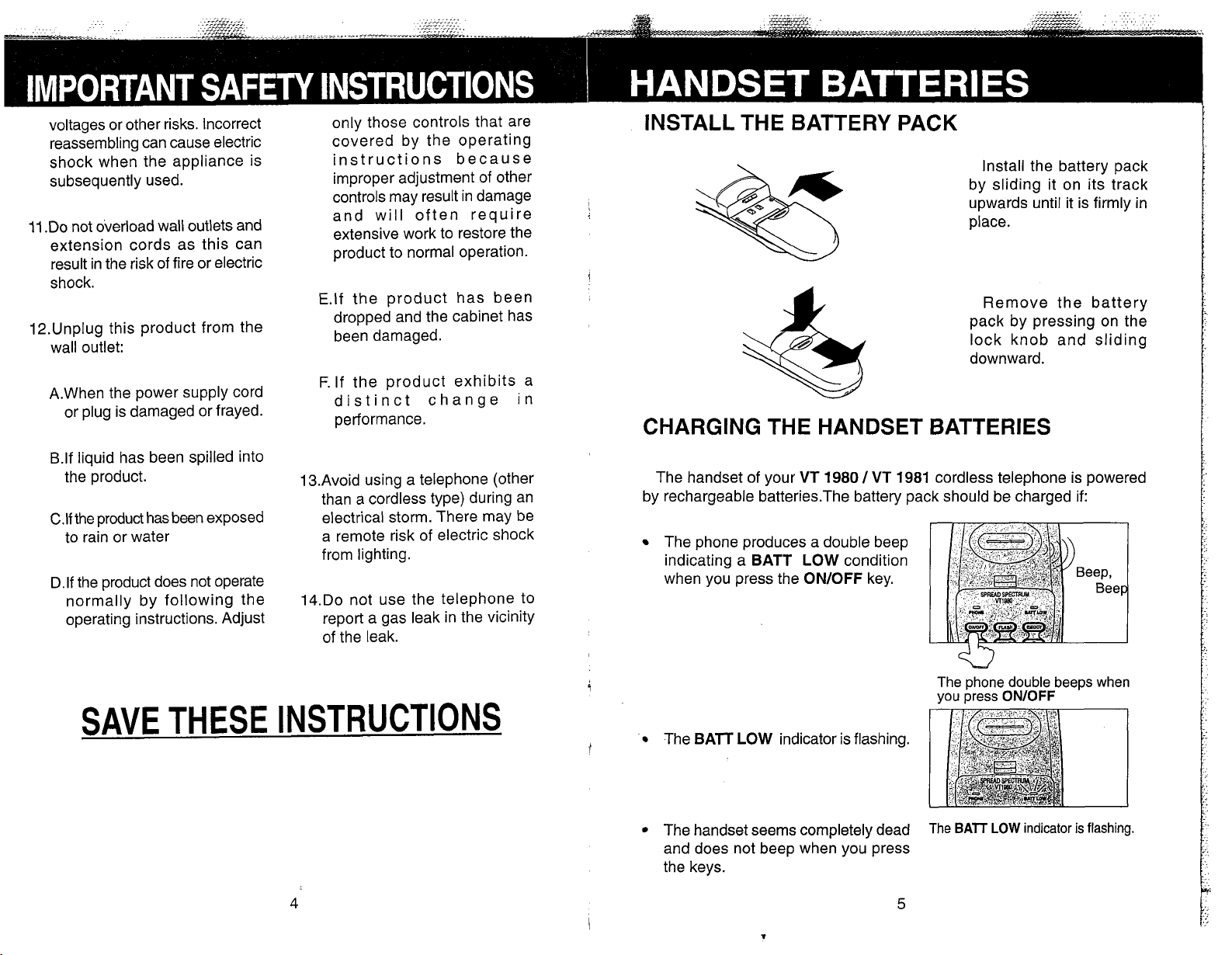
INSTALL THE BATTERY PACK
Install the battery pack
by sliding it on its track
upwards until it is firmly in
place.
Remove the battery
pack by pressing on the
lock knob and sliding
downward.
CHARGING THE HANDSET BATTERIES
The handset of your
by rechargeable batteries.The battery pack should be charged if:
The phone produces a double beep
indicating a
when you press the
BATT
VT
1980
LOW
condition
ONIOFF
1
VT
key.
1981
cordless telephone is powered
SAVE THESE INSTRUCTIONS
The phone double beeps when
you press
The
BAlT
LOW
i'
The handset seems completely dead
and does not beep when you press
the keys.
indicator is flashing.
The
BATT
ONIOFF
LOW
indicator is flashing.
Page 6
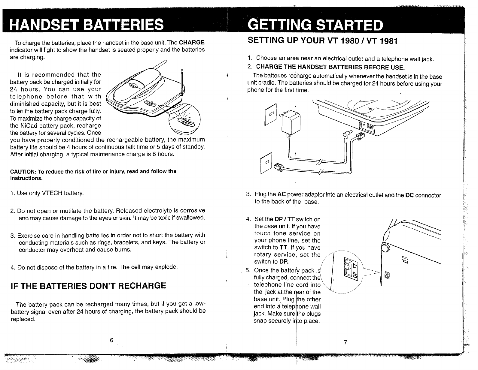
To charge the batteries, place the handset in the base unit. The
indicator will light to show the handset is seated properly and the batteries
are charging.
It is recommended that the
battery pack be charged initially for
24 hours. You can use your
telephone before that with
diminished capacity, but it is best
to let the battery pack charge fully.
To maximize the charge capacity of
the NiCad battery pack, recharge
the battery for several cycles. Once
you have properly conditioned the rechargeable battery, the maximum
battery life should be 4 hours of continuous talk time or
After initial charging, a typical maintenance charge is
5
8
hours.
CHARGE
days of standby.
SETTING
1.
Choose an area near an electrical outlet and a telephone wall jack.
2.
CHARGE THE HANDSET BATTERIES BEFORE USE.
!
The batteries recharge automatically whenever the handset is in the base
unit cradle. The batteries should be charged for 24 hours before using your
phone for the first time.
UP
YOUR
VT 1980 1 VT 1981
CAUTION:
instructions.
1.
Use only VTECH battery.
2.
Do not open or mutilate the battery. Released electrolyte is corrosive
and may cause damage to the eyes or skin. It may be toxic if swallowed.
3.
Exercise care in handling batteries in order not to short the battery with
conducting materials such as rings, bracelets, and keys. The battery or
conductor may overheat and cause burns.
4.
Do not dispose of the battery in a fire. The cell may explode.
IF
The battery pack can be recharged many times, but
battery signal even after 24 hours of charging, the battery pack should be
replaced.
To reduce the risk of fire or injury, read and
follow
THE BATTERIES DON'T RECHARGE
if
the
you get a low-
3.
Plug the
to the back of t$e base.
4. Set the
the base unit. If you have
touch tone service on
your phone line, set the
switch to TT. If you have
I
I
rotary service, set the
switch to
5.
Once the batteh pack
fully charged, connect thei,
telephone line cord into
AC
power adaptor into an electrical outlet and the
DP
/
lTswitch on
DP.
iq
DC
connector
Page 7

6.
CHECK FOR A DIAL TONE.
After the batteries are charged, rotate the base unit antenna to an upright
position.Next, pick up the handset and press the
LED
should light up, and you should hear a dial tone.
ONIOFF
key. The
If
not, see
PHONE
IN CASE
OF DIFFICULTIES.
CAUTION:
1.
Never install telephone wiring during a lightning storm.
2.
Never install telephone jacks in a wet location unless the jack is specifically
designed for a wet location.
3.
Never touch uninsulated telephone wires or terminals unless the
telephone line has been disconnected at the network interface.
4.
Use caution when installing or modifying telephone lines.
Wall Installation Using Mounting
Screws Provided.
The Wall Mount adaptor is
designed to fit on standard Wall
If
Mount plates.
a plate, you should start with step
#4
below.
TOOLS YOU WILL NEED
A hammer, a nail, a pencil or ball-
point pen, a Phillips head
screwdriver, and the Wall Mounting
Template included in the back of
this booklet.
1.
CHOOSE A SPOT NEAR AN
you are using such
:
(+)
ELECTRICAL OUTLET AND A
TELEPHONE. JACK.
Your phone requires a modular
telephone jack and a standard
electrical outlet
power cord is six feet long; make
sure there is an electrical outlet
within reach of the base. The outlet
should not be controlled by a wall
switch. If the switch is ever turned
off, the phone will not operate.
(120V
AC).
The
3.
INSTALL THE MOUNTING
SLEEVES
Start the screw holes by lightly
tapping a nail into the marks you
made on the wall. Remove the nail
from the wall. Now slip the
mounting sleeves onto the screws
as shown, with the smaller end of
the sleeve toward the screw head.
Insert the screws into the holes you
started. Tighten the screws until the
large end of the mounting sleeve
is flat against the wall.
AND
SCREWS.
2.
CHOOSE AND MARK THE
MOUNTING POSITION.
The mounting screws should
screw into a wooden stud within the
wall -they will not hold securely in
wallboard alone. Locate a wall stud
in the area where you want to install
your telephone. Use the Wall
Mounting Template and a pencil to
mark the screw positions on the
wall over the stud. Put the template
aside.
Page 8

4.
POSITION THE WALL MOUNT ADAPTOR ON THE BASE.
lnsert the AC power adaptor cord
and the telephone line cord in the
wall brackedt notches.
Line up the tabs on the wall
mount adapter with the holes on the
bottom of the base. Snap the wall
mount adaptor firmly in place.
Push
in
and
slide down
6.
CONNECT THE TELEPHONE CORD.
The telephone line cord has a
snap-in plug at each end. lnsert
one of the plugs into the jack on
the bottom of the base. lnsert the
other end of the plug into the wall
jack.
7.
CONNECT THE POWER CORD.
Handset
PHONE LED,
Diagram
,
BATT LOW
LED
5.
MOUNT THE BASE ON THE WALL.
Position the base so the
mounting screws will fit into the
holes on the bottom of the base.
Position the power cord to extend
down the wall the phone is to be
mounted on. Slide the base down
on the mounting screws until it
locks into place.
Plug the DC connector into the
DC jack at the rear of the base unit.
Plug the AC power adaptor into an
electrical outlet.
8.
SET THE DIAL MODE SWITCH ON THE BASE UNIT.
If you have touch tone service on
your phone line, set the switch to
TT.
If you have rotary service, set
the switch to DP.
2.5
mm
HEADSET JACK
Page 9
PHONE LED
The
PHONE
the phone line is being used by
the handset.
It flashes during the
programming mode.
It flashes quickly when the line
is on hold.
LED lights when
BATT LOW LED
The
BATT LOW
quickly when the handset
battery is getting low and needs
to be recharged.
It flashes slowly when the
handset is out of the talking
range or the base station is not
powered up.
The
BATT LOW
steadily when
activated.
LED will flash
LED glows
MUTE
ONIOFF KEY
Press the
a call or end a call.
ONIOFF
key to make
FLASH KEY
Press
between calls when Call Waiting
signal is heard.
When in
FLASH
(1,2,3,4)
FLASH
OFF
and a number key
selects the ringer type.
to switch
mode, pressing
MEM KEY
Used to store telephone
numbers in memory and
perform speed number dialing.
RDUP
KEY
When you hear the dial tone,
pressing the RDUP key will dial
is
the last number that was called
on your phone.
It can also be used for a brief
PAUSE
speed numbers.
when programming
HOLD KEY
When using your phone, press
HOLD
To return to the call , press
PHONE
to put a call on hold.
or
HOLD.
EMGCY KEY (EMERGENCY CALL)
One-touch speed dial number
which can be programmed for
#
an emergency
frequently dialed number.
or any other
MUTE KEY
When using your phone, press
MUTE
the microphone.
To reactivate the microphone
press
to temporarily turn
MUTE
again.
off
UP KEY
Used to increase the earpiece
volume during a call.
Used to increase the ringer
OFF
volume during
mode.
DOWN KEY
Used to decrease the earpiece
volume during a call.
Used to decrease the ringer
volume during
OFF
mode.
*/TONE KEY
In
PULSE
used to switch to Temporary
Tone dialing mode.
dialing mode, it is
.-
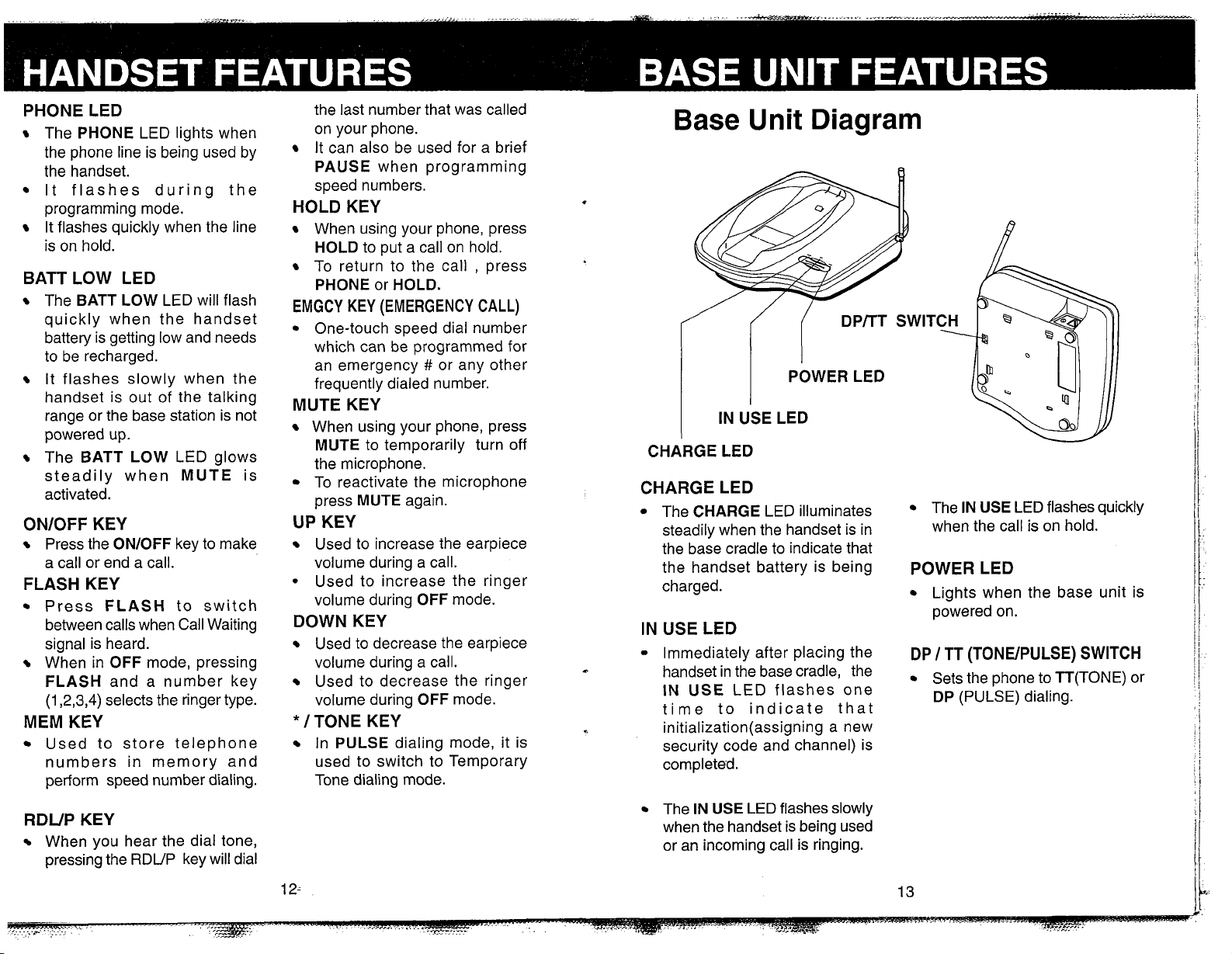
Base Unit Diagram
1
IN
USE
LED
CHARGE LED
CHARGE LED
The
CHARGE
steadily when the handset is in
the base cradle to indicate that
the handset battery is being
charged.
IN USE LED
Immediately after placing the
handset in the base cradle, the
IN
USE
time to indicate that
initialization(assigning
security code and channel) is
completed.
The
IN USE
when the handset is being used
or an incoming call is ringing.
LED illuminates
LED flashes one
a new
LED flashes slowly
The
IN USE
when the call is on hold.
LED flashes quickly
POWER LED
Lights when the base unit is
powered on.
DP
I
TT (TONEIPULSE) SWITCH
Sets the phone to TT(T0NE) or
DP
(PULSE) dialing.
Page 10

MAKING CALLS
TEMPORARY TONE
Pick up the handset and press
ONIOFF.
tone, dial the number. The
LED on the handset and
When you hear a dial
PHONE
IN USE
LED on the base unit will light.
If you make a mistake when
dialing, press
ONIOFF
hang up, then press
again to
ONIOFF
to get
the dial tone again.
You must always press
ONIOFF
before you can dial on the
handset.(Except when using the
EMGCY
key.)
ANSWERING CALLS
When an incoming call is ringing,
the
IN USE
PHONE
flash.
To answer a call when the handset
is in the base, just pick up the
handset.
To answer a call when the handset
is away from the base unit, just press
any key on the handset. This is very
useful in a dark environment; you do
not have to fumble around
for the
LED on the base unit and
LED on the handset will
looking
ONIOFF
key to answer thecall.
TO
ANSWER
TO
MAKE
CALLS:
CALLS : Press
pick
up
the handset,
or
press any key.
dial
ONlOFF
the
number
If you have a rotary (dial-pulse) telephone service. (DP
I
TT
switch is set
to DP), this feature allows you to enter special codes and tones to operate
answering machines, use electronic banking services, calling cards, or other
special services.
,
normally.
First, dial the
&all
M
1
.Dial the
call
Then activate the Temporary Tone
feature by pressiAg
TONE
(the *key).
u
2.Press
You can then press the numbers or
symbols you need, and your phone will
send the proper signals.
I
To end the call . bress
ONIOFF
or place
the handset back in the base unit. The
phone will automatically go back to rotary
(dial-pulse) service.
If you have touch-tone service, (DP
ITT
3.Phone
switch set to
This feature is only for rotary service telephone lines.
PROGRAM ING THE RINGER TYPE
*/TONE
is
now in
TT),
key
TONE
just dial normally.
w
mode.
DISCONNECTING
To end a call, either place the handset back in the base, or press
ONIOFF
on the handset.
er is capable of four different types of ringing tones.
To program, the handset must be
OFF.
Page 11

To select a different ringer type do the
following:
1. Press
2. Press a key 1
A
the new ringer type.
FLASH
..4
to select a ringer type
confirmation ring will be heard for
1
.Press
2,Press a key
MEMORY DIALING (SPEED DIALING)
FLASH
1
..4
SPEED NUMBER DIALING
1.
Press
ONIOFF
2. Press
location number code (01 -20).
to get a dial tone.
MEM
and the memory
The
VT
1980
1
VT
1981
can store up to 21 different phone numbers that
you can dial simply by pressing
(01 -20), or simply by pressing the one-touch
MEM
and the corresponding location code
EMGCY
key.
TO PROGRAMMING SPEED DlAL NUMBERS
The Handset must be
1. Press
blink to indicate that you are in the
programming mode.
2. Using the dial pad, enter the number
you want to store. The number can be
up to 16 digits long.
3.
4.
location you wish to store the number in
(01 -20). lf you wish to program
memory, press
MEM.
The
Press
MEM
once more.
Press the number of the memory
EMGCY.
OFF.
PHONE
LED
will
EMGCY
TO PROGRAM SPEED
DlAL NUMBERS
Press
MEM
Enter
the
number
you
Press
MEM
Enter the memory location
you wish to store-
want
again
to
store
-
For example, to dial the number you
assianed to location 18, vou would 2.Press
presi
ONIOFF, MEM,
I,'&
W
MEM
3.Enter memory location
EMERGENCY SPEED NUMBER DIALING (EMGCY
The
EMGCY
used for emergency numbers, like
number. It is important to note that
which will be dialed when you press
PROGRAM THIS NUMBER.
To dial using the
handset
you have stored in the
advance,and then press the
.
You can also dial the
key is a dedicated speed dial key which is designed to be
911,
or for another frequently dialed
YOU
MUST PROGRAM THE NUMBER
EMGCY. VTECH DOES NOT PRE-
EMGCY
The phone will automatically access dial tone, and dial the number
key you can simply press
EMGCY
location.
EMGCY
EMGCY
number by pressing
key.
EMGCY
ONIOFF
TO CHANGE OR REPLACE A SPEED DlAL
NUMBER
key)
on the
in
The phone now exits programming mode and emits two beeps.
To change or replace a stored number in speed dial, simply enter the
new number and store it in the memory location you wish to change.
Page 12

STORING PAUSES IN MEMORY USING REDIAL
The
VT
1980
I
VT
1981
To insert a pause in a phone number, press RDLIP at the appropriate
2
point when storing the number. This inserts a
pauses, press RDUP two or more times. Each press makes the pause
seconds longer and is treated as a stored digit.
If your phone is connected to a
number and a pause before the phone number.
PBX
second pause. For longer
you can store the
PBX
access
2
I
1
number you dialed in a special redial memory.
To dial the number again,
press
ONIOFF,
to get dial tone.
cordless phone automatically stores the last
For example, to store
following:
1.
Press
MEM
2.
Press
9
3.
Press
RDUP
4.
Press
5551234
,
5.
Press
MEM
9-PAUSE-5551 234
C
in memory location
18,
do the
then press
The phone will automatically dial the number.
RDUP.
2.Press
RDUP
TO PUT A CALL ON HOLD
While using your phone, you can put a call on hold by pressing
The
PHONE
To return to the call, press
using the
same line, the
Therefore, you do not have to go back to turn the phone off if you go to
another extension. It is done automatically.
LED on the handset will flash quickly to show a call is on hold.
VT
1980
VT
I
VT
1980
ONIOFF
1981
and the user picks up another phone on the
I
VT
1981
or
HOLD
will take itself off hold and turn off.
again. If a call is on hold
HOLD.
6.
Press
1,8
PRESS
pick up another extension on the same line.
ONIOFF
or
HOLD
(on the
VT
1980 / VT
1981)
to take call off hold, or
Page 13

THE MUTE FEATURE
When you press
your phone, you can hear the caller's
voice, but they cannot hear you. You
can use this feature to speak to
someone in the room without the caller
listening. While a call is muted the
BATT
LOW
be on.
To go back to the two-way conversation,
press
MUTE
MUTE
LED on the handset will
again.
while using
VOLUME CONTROL
MUTE
Press
the caller can not hear your voice
Press
MUTE
to the two-way conversation
to return
An optional handset charging cradlelspare Battery Charger is available
for use with the
This allows the user to remotely charge a Spare Battery and Handset
while it is away from the Base Unit.
VT 1980 I VT 1981.
SETTING UP THE HANDSET CHARGING CRADLE /SPARE BATTERY CHARGER
(Optional
1.
Choose an area near an electrical outlet,
2.
Plug the AC power adaptor into an electrical outlet and the DC connector
into the bottom of the charger.
for
VT
1980)
During a call, press
DOWN
the earpiece volume. Three rapid
beeps will be heard when you reach
the highest or lowest volume level.
keys to increase or decrease
the(^)
UP
or(-)
UP
(A)
and
earpiece volume during a call
TO PRESET THE RINGER VOLUME
The
VT 1980 1 VT 1981
ringer volume levels. To preset the
ringer volume, the phone must be
Press the
confirmation-ring will be heard for the
new ringer volume level.
(&)UP
or(-)
DOWN
has two
OFF.
keys, a
UP
(4
and
ringer volume when phone is
DOWN (r)
DOWN(-)
keys control
keys preset
OFF
3.
Place the Spare Battery in the charging
slot.The Spare Battery LED will glow
steadily.
4.
Place the Handset in the charging
base.The Handset Charging LED will
glow steadily.
Page 14

Your
VT 1980 / VT 1981
cordless
telephone is equipped with a
2.5mm Headset Jack for use with
an optional accessory Headset for
hands-free operation.
If you choose to use the Headset
option, you must do the following:
INSTALLATION
Obtain an optional accessory
Headset, which is compatible with
VT l98OIVT 1981.
the
Once you have a compatible
2.5mm Headset, locate the
Headset Jack on the Handset of
VT 1980 / VT 1981.
your
the plug on the Headset to the jack
on the cordless Handset. The plug
should fit securely. Do not force
the connection. See illustration.
Connect
VT 1980 / VT 1981
The
is also
equiped with a detachable belt clip.
Align the pins on the inside edge
of the belt clip with the notches on
the side of the
VT 1980 / VT1981
Handset. The belt clip should snap
securely into place. Do not force
the connection. See Illustration.
OPERATION
Note: whenever a compatible
Headset is connected to the
cordless Handset, the microphone
on the Handset will be
This is done to limit the effect of
background noise.
The following operational
characteristics apply to VTech
Headsets. The same may also
apply to other (non-VTech)
compatible headsets, but VTech
assumes no responsibility for their
performance.
MUTED.
The VTech brand compatible
Headset has a monaural design
which is reversible, so you can
wear your Headset on either the left
or right ear, leaving one ear free for
room conversation.
ON
ON
RIGHT
EAR
LEFT EAR
The headband can be adjusted
to fit the contour of your head.
Using both hands, slide the
headband up or down so that it
rests comfortably on your head with
the speaker cushion centered
against your ear.
For maximum sound quality, the
flexible microphone should be
positioned at the corner or your
mouth, about one inch from your
face.
Page 15

TAKING CARE OF YOUR TELEPHONE
Your
VT 1980 I VT 1981
electronic parts so it must be treated with care.
cordless telephone contains sophisticated
If you have difficulty operating your phone, the suggestions below should
solve the problem. If you still have difficulty after trying these suggestions,
call:
VTECH Communications at 1-800-595-9511
Electronics at 1-800-267-7377.
,In Canada call
VTECH
AVOID ROUGH TREATMENT
Place the handset down gently. Save the original packing material to
protect your telephone if you ever need to ship it.
AVOID WATER
Your telephone can be damaged if it gets wet. Do not use the handset
outdoors in the rain, or handle it with wet hands. Do not install your base
unit near a sink, bathtub or shower.
ELECTRICAL STORMS
Electrical storms can sometimes cause power surges harmful to electronic
equipment.
For your own safety, use caution when using electric appliances during
storms.
CLEANING YOUR TELEPHONE
Your telephone has a durable plastic casing that should retain its luster
for many years. Clean it only with a soft cloth slightly dampened with water
or a mild soap. Do not use excess water or cleaning solvents of any kind.
Problem Remedy
THE PHONE DOESN'T WORK AT ALL
NO DIAL TONE
you
STATIC, OR
SIGNAL EVEN WHEN Then press
Y
BASE UNIT same circuit as the base unit can
GET NOISE, Place the handset in the base
A
WEAK momentarily to reset the security code.
0 U '
R E N EAR T H E Household appliances plugged into the
Make sure the power cord is plugged in.
0
Make sure the telephone line cord is
plugged firmly into base unit and the
telephone wall jack.
Make sure the batteries are properly
BATT
LOW
charged. If the
the battery needs charging. If the
PHONE
press
batteries.
If
you recently installed a new battery
pack, make sure it is installed correctly.
First check all the suggestions above.
If
disconnect the base unit from the
telephone jack and connect a different
phone. If there is no dial tone on that
phone either, the problem is in your
wiring or local service. Call your local
telephone company.
sometimes cause interference. Try
moving the appliance or the base unit
to another outlet.
LED
does not light when you
ONIOFF,
you still don't hear a dial tone,
you must charge the
ONIOFF
to get a line.
LED is on,
Page 16
Problem Remedy
Problem Remedy
YOU GET NOISE, You may be out of range. Either move
STATIC, OR A WEAK closer to the base, or relocate the base
SIGNAL WHEN YOU'RE unit.
AWAY
UNIT
THE
HANDSET
NOT RING WHEN YOU
RECEIVE A CALL
YOUR CALLER FADES
IN AND OUT
Y
0
U H E A R OT H E R Replace the handset in the base cradle,
CALLS WHILE USING wait a few moments and try again.
YOUR PHONE
lHE
BASE
DOES
The layout of your home may be limiting
the range. Try moving the base unit to
the second or third floor, or to some other
location.
Make sure the telephone line cord is
plugged firmly into the base unit and the
telephone jack. Make sure the power
cord is plugged in.
You may be too far from the base unit.
You may have too many extension
phones on your telephone line to allow
them all to ring. Try unplugging some of
the other phones.
You may be nearly out of range. Move
closer, or relocate the base.
Disconnect your base unit from the
telephone jack, and plug in a regular
telephone. If you still hear other calls,
the problem is probably in your wiring or
local service. Call your local telephone
company.
COMMON CURE FOR
ELECTRONIC
EQUI.PMENT
Electronics
get confused. If the unit does not seem to
be responding normally, then try putting the
handset in the cradle for
re-initialize the unit. If it still does not seem
to respond, perform the following steps (in
the order listed):
1.
Disconnect the power to the base.
2.
Disconnect the handset battery.
3.
Wait a few minutes.
4.
Connect power to the base.
5.
Connect the handset battery.
6.
Put the handset in the base to re-initialize.
,
like people , can sometimes
5
to
10
seconds to
YOU HEAR NOISE IN THE
HANDSET AND NONE OF
THE KEYS OR BUTTONS
WORK
Make sure the power cord is plugged in.
Your base unit and handset may not be
operating on the same channel or
security code. Place the handset in the
cradle for a few moments to reload the
security code and reset the channel.
Page 17
WHAT DOES OUR WARRANTY COVER
Any defect in material or workmanship.
-A;..
?
FOR HOW LONG AFTER THE ORIGINAL
PURCHASE
To the original purchaser only-ONE YEAR.
WHAT WILL VTECH DO
At our option, repair or replace your unit.
HOW DO I SEND MY UNIT,
WARRANTY
In the US call VTECH Communications customer service for Return
Authorization at: 1-800-595-9511 ,in Canada call VTECH Electronics
at 1-800-267-7377.
Properly pack your unit. Include any cables & accessories which were
originally provided with the product. We recommend using the original
carton and packing materials.
Include in the package
date of original purchase (if the unit was purchased within the last twelve
mouths.)
Print your name and address, along with a description of the defect,
and include this in the package.
Include payment for any service or repair not covered by warranty, as
determined by VTECH Communications.
Ship the unit via UPS Insured, or equivalent to:
?
?
IN
OR OUT
?
/
a
copy of the sales receipt or other evidence of
VTECH COMMUNICATIONS
8770
SW NIMBUS AVENUE
BEAVERTON, OREGON
IN Canada VTech Electronics
Suite
200
7671
Alderbridge
Richmond, B.C.
V6X
1Z9
OF
97008
Way
WHAT DOES OUR WARRANTY NOT COVER
Batteries
Damage from misuse, neglect, or acts of nature (lightning, floods, power
surges, etc.)
Products which may have been modified or incorporated into other
products
Products purchased
Canada.
Products serviced by the owner or a service facility not expressly
authorized by VTECH Communications
Products purchased more than 12 mouths from current date
Units purchased in "AS
Merchandise".
and/or operated outside the USA, its territories, or
IS"condition, or units purchased asUDistressed
?
HOW DOES STATE LAW OR PROVINCIAL LAW
RELATE TO THIS WARRANTY?
This warranty gives you specific rights. You may also have other rights
which vary from state to state or from province to province.
1
!
VTECH Communications assumes no responsibility for units sent without
prior Return Authorization.
Page 18
This equipment complies with
Part 15 and 68 of the Federal
Communications Commission
(FCC) rules for the United States.lt
also complies with rules RSS-210
and CS-03 of Industry Canada (IC)
for Canada.
A label is located on the
underside of the base unit
containing either the FCC
registration number and Ringer
Equivalence Number (REN) or the
IC registration number .You must,
upon request, provide this
information to your local telephone
company.
This equipment is compatible
with inductively coupled hearing
aids.
Should you experience trouble
with this telephone equipment,
please contact:
VTECH COMMUNICATIONS AT
1-800-595-951 1 in the US
and VTECH ELECTRONICS AT
1-800-267-7377 in Canada.
/
for repair
The telephone company may ask
you to disconnect this equipment
from the line network until the
problem has been corrected.
Your
designed to operate at the
maximum power allowed by the
FCC and IC. This means your
handset and base unit can
warranty information.
VT
1980
/
VT
1981
is
communicate only over a certain
distance -which will depend on the
location of the base unit and
handset and layout of your home
or office.
FCC
and found to comply with part 15
of the FCC rules. These limits are
designed to provide reasonable
protection against harmful
interference in a residential
installation. This equipment
generates, uses and can radiate
radio frequency energy and, if not
installed and used in accordance
with the instructions, may cause
harmful interference to radio
communications. However, there is
no guarantee that interference will
not occur in particular installation.
If this equipment does cause
harmful interference to radio or
television reception, which can be
determined by turning the
equipment off and on, the user is
encouraged to try and correct the
interference by one or more of the
following measures:
-
-
PART
The equipment has been tested
Reorient or relocate the
receiving antenna.
Increase the separation
between the equipment and
receiver.
15
-
Connect the equipment into an
outlet or on a circuit different
from that to which the receiver
is connected.
-
Consult the dealer or an
/
experienced radio
technician for help.
FCC
connect your cordless telephone to
the nationwide telephone network
through a modular telephone jack
(USOC, RJ11 C or RJl 1
discontinue your service if your
equipment causes harm to the
telephone network. They will notify
you in advance of disconnection, if
possible. During notification, you
will be informed of your right to file
a complaint with the FCC.
company may make changes in its
facilities, equipment, operation, or
procedures that could affect the
operation of your equipment. If so,
you will be given advance notice
of the change to give you an
opportunity to maintain
uninterrupted service.
PART
The FCC requires that you
Your telephone company may
Occasionally your telephone
68
W)
TV
The base unit contains no user
serviceable parts. The handset
contains a user replaceable battery
pack.
If it is determined that your
telephone equipment is malfunctioning,
the FCC requires that it not be used
and that it be unplugged from the
modular jack until the problem has
been corrected. Repairs to this
telephone equipment can only be
made by the manufacturer or its
authorized agents or by others who
may be authorized by the FCC. For
repair procedures, follow the
instructions outlined under the
VTECH Limited Warranty.
This equipment may not be used
on coin service provided by the
phone company or Party lines.
The REN is useful in determining
the number of devices you may
connect to your telephone line and
still enable the devices to ring when
you receive a call. The general rule
is that the REN value should not
exceed
contact your local telephone
company for the specific number in
your area.
5.OA total; however,
Page 19
IC (Industry Canada)
This telephone is registered
for use in Canada.
Notice:The REN assigned to
this device denotes the
number of devices you may
connect to the telephone
loop which is used by the
device to prevent
overloading. The
termination on a loop may
consist of any combination
of devices subjected only to
the requirement that the
sum of the REN does not
exceed five (5.0).
any interference, including
interference that may cause
undesired operation of the
device.
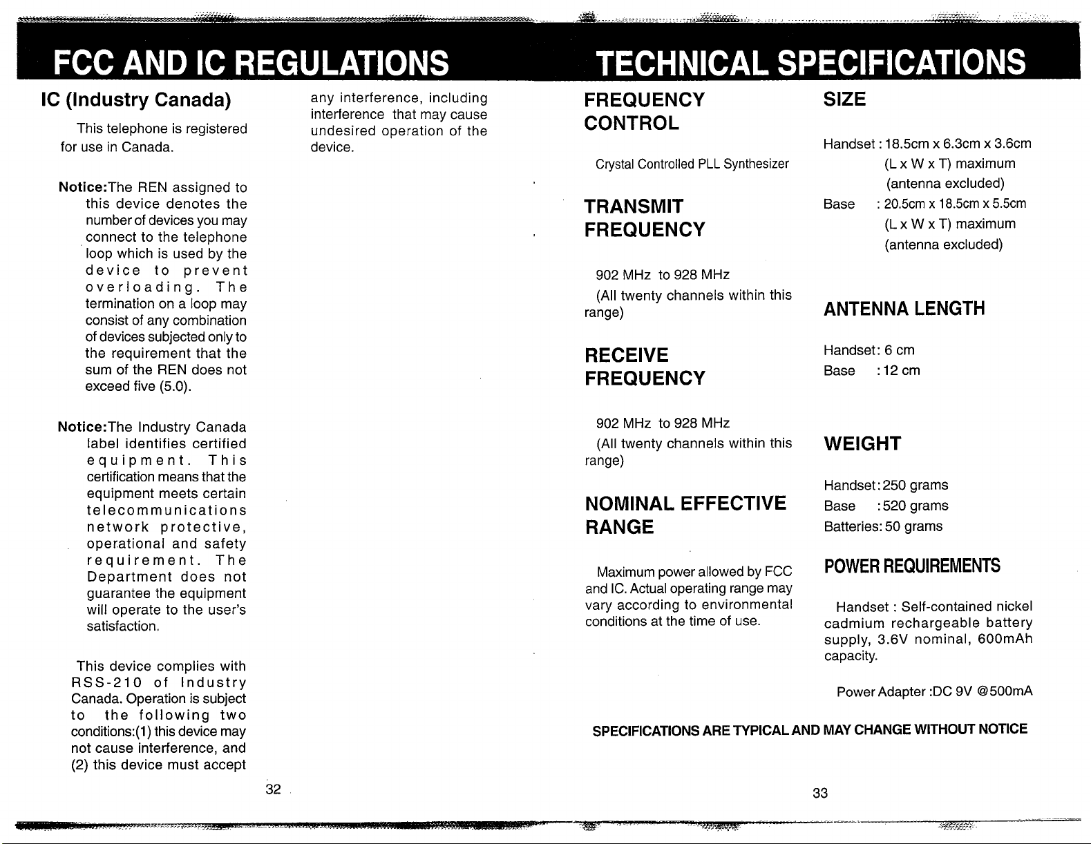
FREQUENCY
CONTROL
Crystal Controlled
PLL
Synthesizer
TRANSMIT
FREQUENCY
902 MHz to 928 MHz
(All twenty channels within this
range)
RECEIVE
FREQUENCY
SIZE
Handset : 18.5cm x 6.3cm x 3.6cm
W
x T) maximum
(antenna excluded)
W
x T) maximum
Base
(L x
:
20.5cm x 18.5cm x 5.5cm
(L x
(antenna excluded)
ANTENNA LENGTH
Handset: 6 cm
Base
:
12
cm
Notice:The lndustry Canada
label identifies certified
equipment. This
certification means that the
equipment meets certain
telecommunications
network protective,
operational and safety
requirement. The
Department does not
guarantee the equipment
will operate to the user's
satisfaction.
This device complies with
RSS-210 of lndustry
Canada. Operation is subject
to the following two
conditions:(l) this device may
not cause interference, and
(2) this device must accept
902 MHz to 928 MHz
(All twenty channels within this
range)
NOMINAL EFFECTIVE
RANGE
Maximum power allowed by
and IC. Actual operating range may
vary according to environmental
conditions at the time of use.
SPECIFICATIONS ARE TYPICAL AND MAY CHANGE WITHOUT NOTICE
FCC
WEIGHT
Handset: 250 grams
:
Base
Batteries: 50 grams
POWER
Handset
cadmium rechargeable battery
supply,
capacity.
Power Adapter :DC 9V 8500mA
520 grams
REQUIREMENTS
:
Self-contained nickel
3.6V nominal, 6OOmAh
Page 20
VTECH VT 1980
/
VT 1981 Cordless
Telephone
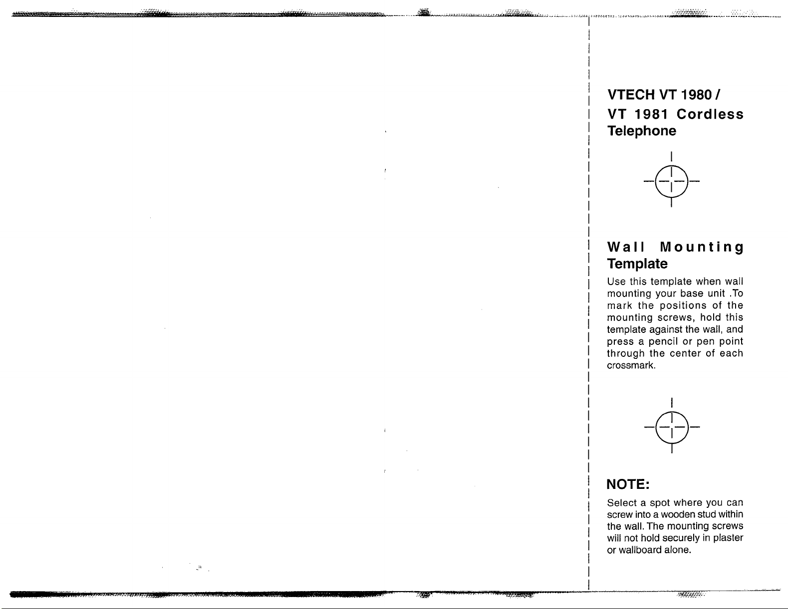
Wall
Mounting
Template
Use this template when wall
mounting your base unit .To
mark the positions of the
mounting screws, hold this
template against the wall, and
press a pencil or pen point
through the center of each
crossmark.
NOTE:
Select a spot where you can
screw into a wooden stud within
the wall. The mounting screws
will not hold securely in plaster
or wallboard alone.
 Loading...