

Page 1

Table of contents
Getting started . . . . . . . . . . . . . . . . . . . . . 4
Parts checklist . . . . . . . . . . . . . . . . . . . . . . 4
Installation . . . . . . . . . . . . . . . . . . . . . . . . 5
Choose location . . . . . . . . . . . . . . . . . . . . 5
Install handset battery . . . . . . . . . . . . . . . . . 5
Connect power to base unit/chargers . . . . . . . . . 6
Connect to phone line . . . . . . . . . . . . . . . . . 6
Check battery indicator . . . . . . . . . . . . . . . . 7
Check for dial tone . . . . . . . . . . . . . . . . . . . 7
If you subscribe to DSL service . . . . . . . . . . . . 8
Belt clip (optional) . . . . . . . . . . . . . . . . . . . 8
Wall mounting (optional) . . . . . . . . . . . . . . . . . 9
Handset layout . . . . . . . . . . . . . . . . . . . . . 10
Base unit layout. . . . . . . . . . . . . . . . . . . . . 11
Basic operation . . . . . . . . . . . . . . . . . . . . 12
Handset icons . . . . . . . . . . . . . . . . . . . . 12
Handset LEDs . . . . . . . . . . . . . . . . . . . . 12
Base LEDs . . . . . . . . . . . . . . . . . . . . . . 12
Handset operation . . . . . . . . . . . . . . . . . . 13
Making calls . . . . . . . . . . . . . . . . . . . . . 13
Answering calls . . . . . . . . . . . . . . . . . . . 13
Adjust handset volume . . . . . . . . . . . . . . . . 13
Flash function . . . . . . . . . . . . . . . . . . . . 13
Redial . . . . . . . . . . . . . . . . . . . . . . . . 14
Mute . . . . . . . . . . . . . . . . . . . . . . . . . 14
Intercom . . . . . . . . . . . . . . . . . . . . . . . 14
Call forward . . . . . . . . . . . . . . . . . . . . . 15
Call transfer . . . . . . . . . . . . . . . . . . . . . 16
Conference call . . . . . . . . . . . . . . . . . . . 16
Find Handset . . . . . . . . . . . . . . . . . . . . . 16
Voice mail service . . . . . . . . . . . . . . . . . . 16
Telephone directory . . . . . . . . . . . . . . . . . . 17
Store a new entry . . . . . . . . . . . . . . . . . . 17
Characters by number . . . . . . . . . . . . . . . . 18
Review/dial from the directory . . . . . . . . . . . . 19
Edit a directory entr y . . . . . . . . . . . . . . . . . 19
Delete a directory entry . . . . . . . . . . . . . . . 20
Caller ID . . . . . . . . . . . . . . . . . . . . . . . . 21
Caller ID - call waiting ID . . . . . . . . . . . . . . . 21
Review caller ID . . . . . . . . . . . . . . . . . . . 22
Store caller ID . . . . . . . . . . . . . . . . . . . . 22
Dial from caller ID . . . . . . . . . . . . . . . . . . 24
Delete caller ID. . . . . . . . . . . . . . . . . . . . 24
Handset settings . . . . . . . . . . . . . . . . . . . . 25
Ringer volume . . . . . . . . . . . . . . . . . . . . 25
Key tone . . . . . . . . . . . . . . . . . . . . . . . 25
Language . . . . . . . . . . . . . . . . . . . . . . 26
Clear voice mail . . . . . . . . . . . . . . . . . . . 26
Dial type . . . . . . . . . . . . . . . . . . . . . . . 26
Headset operation . . . . . . . . . . . . . . . . . . . 27
Headset . . . . . . . . . . . . . . . . . . . . . . . 27
Operating range . . . . . . . . . . . . . . . . . . . . 27
Batteries . . . . . . . . . . . . . . . . . . . . . . . . 28
Battery care and per formance . . . . . . . . . . . . 28
Replace handset battery . . . . . . . . . . . . . . . 28
Additional information . . . . . . . . . . . . . . . . 29
Page 2

Table of contents
Troubleshooting . . . . . . . . . . . . . . . . . . . . 29
Maintenance . . . . . . . . . . . . . . . . . . . . . . 35
Warranty . . . . . . . . . . . . . . . . . . . . . . . . 35
Important safety instructions . . . . . . . . . . . . . . 37
FCC, ACTA and IC regulations . . . . . . . . . . . . . 38
The RBRC® Seal . . . . . . . . . . . . . . . . . . . . 39
Technical specications . . . . . . . . . . . . . . . . 40
Index . . . . . . . . . . . . . . . . . . . . . . . . . . 41
Page 3

NEED HELP?
This manual has all the feature operations and troubleshooting you need to
install and operate your new VTech telephone. Please take the time to review
thoroughly to ensure proper installation of this VTech innovative and feature
rich product. You can also visit our website at www.vtechphones.com for
support, shopping, and everything new at VTech.
In Canada, please visit www.vtechcanada.com.
VTech toll free 1-800-595-9511
In Canada dial 1-800-267-7377
Page 4
• Before using
this telephone,
you must read
Important
safety
instructions on
page 37.
Getting started
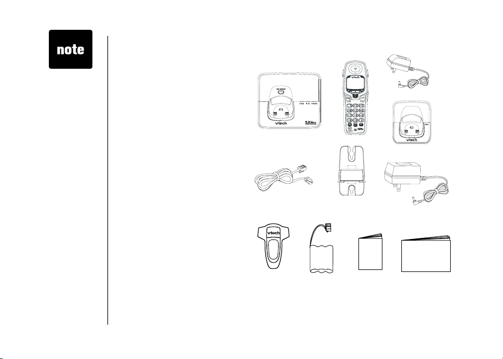
Parts checklist:
1. Base unit
2. Handsets (3)
3. Charger power adaptors (2)
4. Chargers (2)
5. Telephone line cord
6. Wall mount bracket
7. Belt clips (3)
8. Base power adaptor
9. Batter y packs (3)
10. User’s manual
11. Quick Start Guide
To p u r c ha se re p l a c e m en t
battery packs, visit us on the
web at www.vtechphones.com
or call VTech Communications,
In c. at 1- 8 0 0-595 - 9 511. In
C a na da , c on t ac t V Te c h
Telec ommunications Canada
Ltd. at www.vtechcanada.com
or 1-800-267-7377.
Base unit
Telephone line cord
Belt clips (3)
Batteries (3)
Handsets (3)
Wall mount
bracket
Quick Start Guide
Charger power adaptors (2)
Chargers (2)
Base power Adaptor
User’s manual
4
www.vtechphones.com
Page 5
Installation
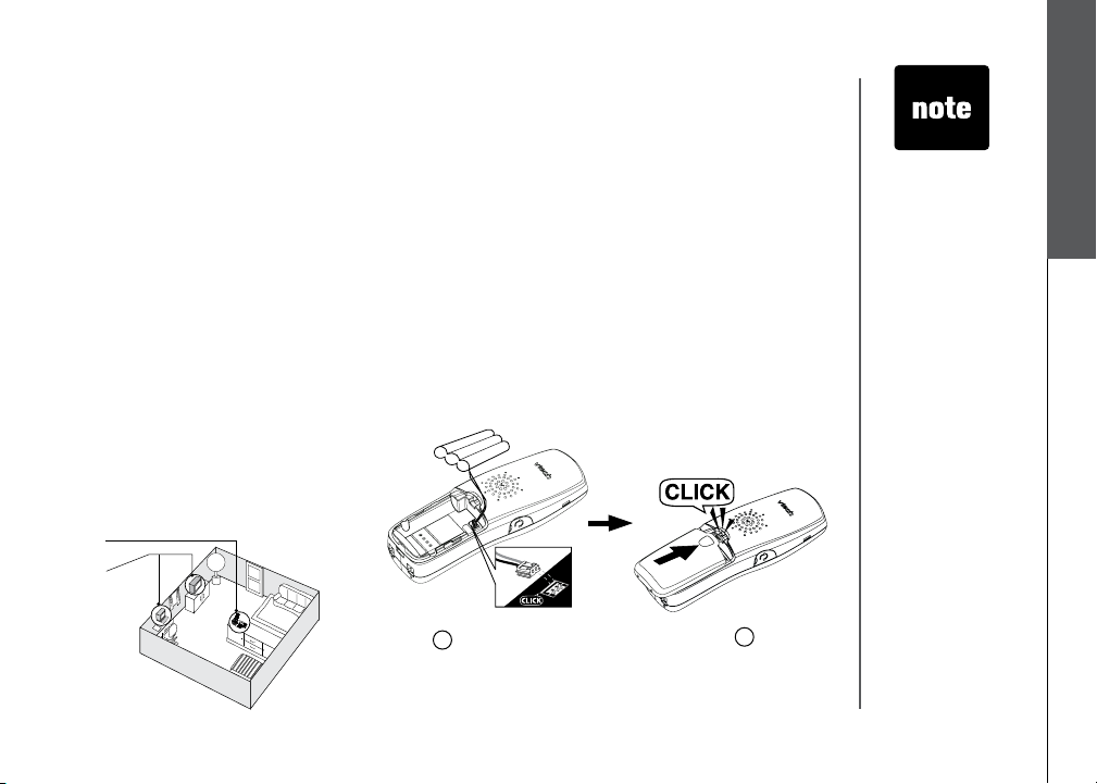
Choose location
For maximum perform an ce of your
cordless telephone system:
1. Choose a central location for your
base unit.
2. Install your phone(s) as far away as
possible from any other cordless
(wireless) device such as cordless
telephones, 802.11 wireless router
(for example, WiFi).
3. Install your phone(s) as far away
as possible from other electronic
eq u i p m ent su c h as mi c rowa ve
ovens, televisions, computers, etc.
4. Install your telephone equipment
away from heat sources and direct
sunlight.
5. Avoid excessive moisture, dust or
extreme cold.
1.
2.
Install handset battery
1.
Align the two holes in the plug with the socket pins, matching
the red and the black connectors, then snap the plug
into place.
2. Place the battery in the compartment with the wires in
the upper right corner.
3. Replace cover by sliding it upwards until it clicks into
place.
4. Be sure to charge the battery for 16 hours before using
your phone.
1
www.vtechphones.com
3
Getting started
• Use only the
provided VTech
battery, or
equivalent.
• Place the
handset in
its base or
charger when
not in use to
ensure optimum
performance.
• if you need
to install your
phone within
the same
room as other
cordless phones
or wireless
products, you
may need to
select a different
channel for
your router and
or change the
channel on
your phone’s
handsets.
5
Page 6
• Connect the power
and telephone
line cords to the
underside of the
base as illustrated.
• Plug the AC
adaptor into an
electrical outlet. If
the battery has not
been charged,
place the handset
in the base or
charger, and allow
it to charge for at
least 16 hours.
• Be sure to use an
electrical outlet not
controlled by a wall
switch.
Installation
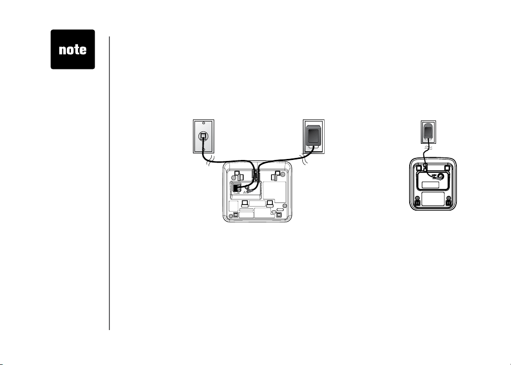
Connect power to base unit/chargers
1. Plug the power adaptor into an electrical outlet not controlled by a wall switch, and the connector
into the bottom of the base unit.
2. Choose the location for your charger, and plug its power supply into an electrical outlet.
To telephone outlet
Connect to phone line
Plug one end of the telephone line cord into the telephone line jack at the bottom of the telephone
base. Then plug the other end of the cord into the wall telephone outlet.
To power outlet
6
www.vtechphones.com
Page 7

Installation
Check battery indicator
When the handset displays WARNING CHECK BATTERY, it indicates one of the following:
1. There is no battery in your handset. You need to install the supplied battery into your handset (see
Install handset battery on page 5.)
2. The battery needs to be replaced.
Getting started
3. The battery has been installed incorrectly. Please reinstall (see
see the diagram in the battery compartment of the handset.
Install handset battery) and/or
Check for dial tone
After the battery is charged, press or SPEAKER on the handset. You should hear a dial tone.
If not, see the Troubleshooting section near the end of this user’s manual.
CAUTION: Use only the VTech power supply provided with your telephone.
www.vtechphones.com
7
Page 8

• If the phone will
not be used for
a long period of
time, remove the
battery pack to
prevent possible
leakage.
• If you have any
trouble installing
your phone,
please refer to the
Troubleshooting
section near the
end of this manual.
When in LOW
•
BATTERY
mode, the
keypad sounds,
backlighting and
speakerphone
features will not
work. When the
battery has been
charged, these
features will return
to their normal
function.
8
Installation
If you subscribe to DSL service
If you hear interference during conversations, and/or your caller ID features are not functioning
properly, and you subscribe to DSL ser vice from your telephone company, install a noise lter to
the telephone line between the base unit and the telephone line jack. Contact your DSL provider to
obtain a noise lter.
T e l ep h o ne
line cord
Belt clip (optional)
www.vtechphones.com
Noise lter (For
DSL users)
To single telephone jack
(RJ11C)
To removeTo attach
Page 9
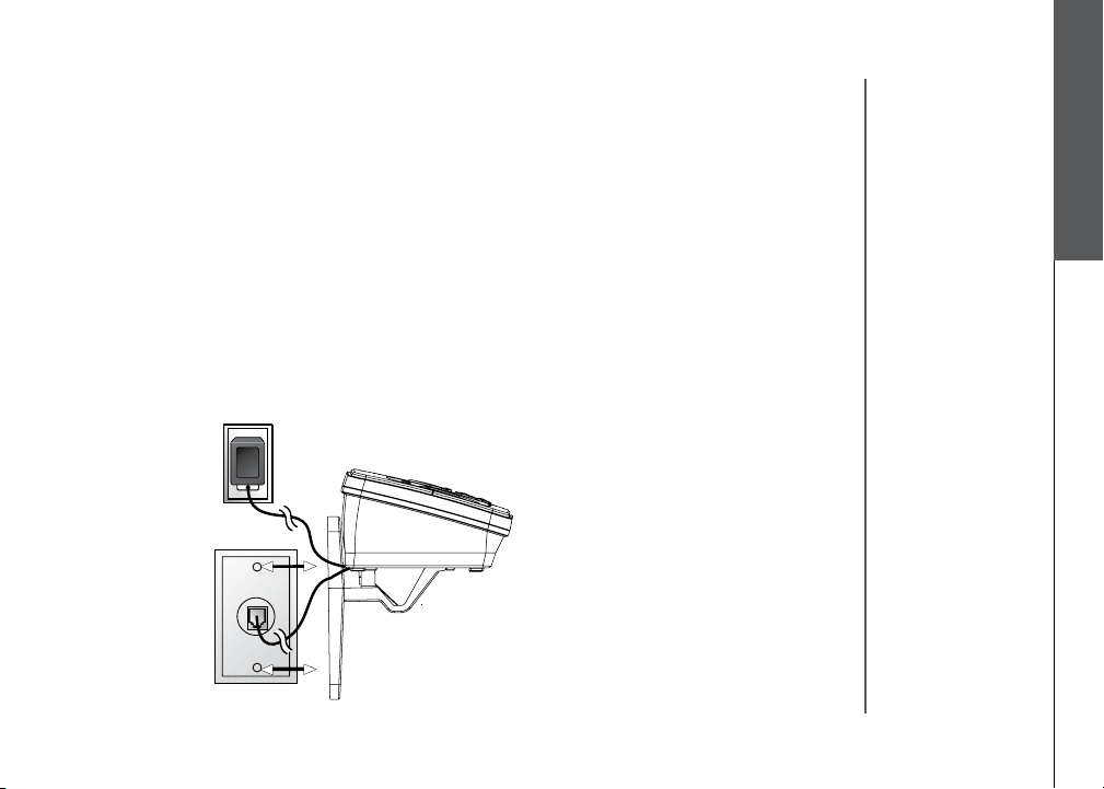
Wall mounting (optional)
The wall mount brackets are designed for use on standard wall mount plates only.
1. Plug the connector of the base power adaptor to the connector jack at the bottom of the base unit.
Then plug the adaptor into an electrical outlet.
2. Connect the telephone line cord to the jack at the bottom of the base unit, and the other end to
the wall jack.
3. Line up the tabs on the wall mount adaptors with the holes at the bottom of the base unit/back of
the charger. Snap the wall mount bracket rmly in place.
4. Mount the base unit on the wall. Position the base unit so that the mounting studs will t into the
holes on the wall mount bracket. Slide base unit down on the mounting studs until it locks into
place.
Getting started
www.vtechphones.com
9
Page 10
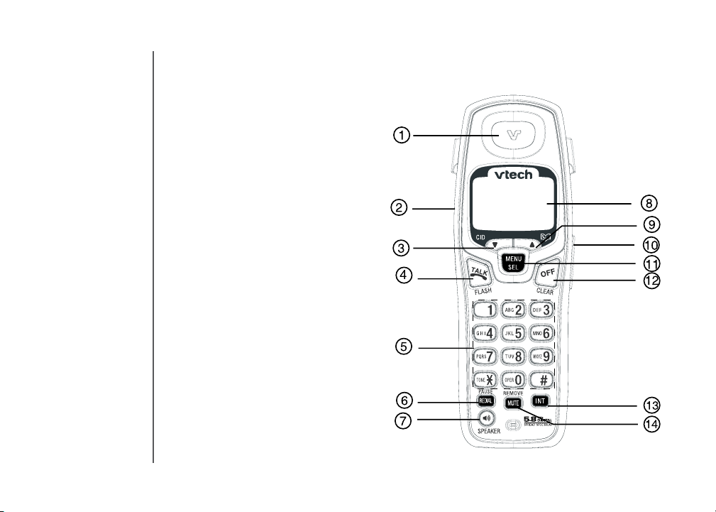
Handset layout
1. Earpiece
2. Headset jack (2.5mm)
3. Caller ID (scroll down)
4. Talk/ash
5. Dialing keys (0-9, *, #)
6. Redial/pause
7. Speaker
8. LCD display
9. Director y (scroll up)
10. Volume control
11. Select/menu
12. Off/clear
13. Intercom
14. Mute/remove
10
www.vtechphones.com
Page 11
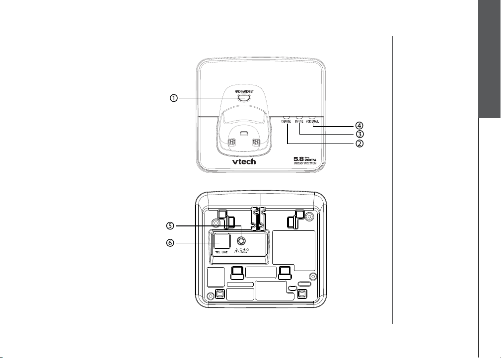
Base unit layout
1. Find handset
2. Charge
3. In use
4. Voice mail
5. Power connector jack
6. Telephone jack
Getting started
www.vtechphones.com
11
Page 12
Basic operation
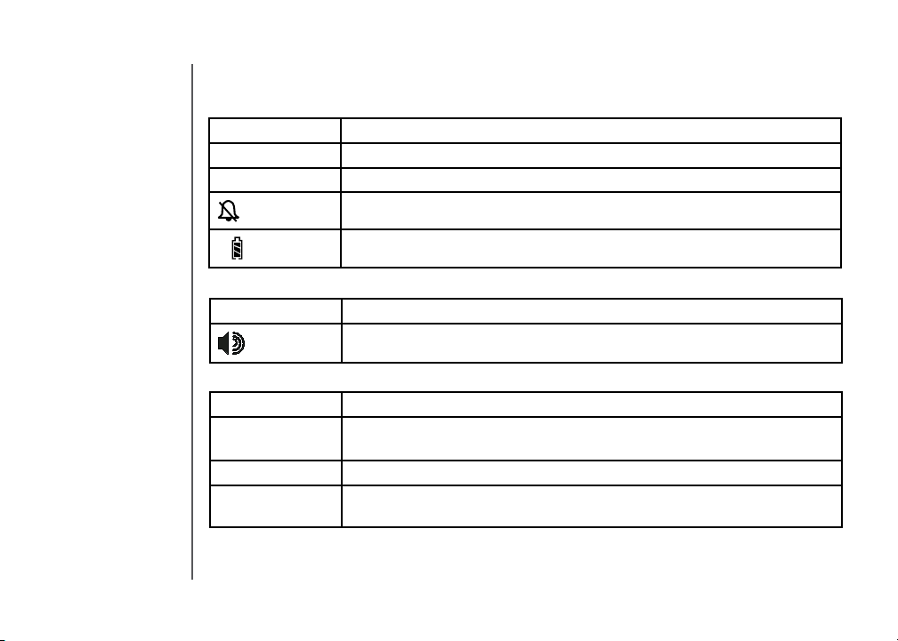
Handset icons
Icon Description
MUTE • On when the microphone is muted, see page 14.
NEW • On when there are new calls in the call log, see page 22.
• On when the handset ringer is muted, see page 25.
• Low battery or charging indicator, see page 8.
Handset LEDs
Icon Description
• On when handset speakerphone is in use.
Base LEDs
Icon Description
IN USE • On when the phone is on a call.
• Flashes when an extension phone is on a call.
CHARGE • On when handset is positioned so its battery can charge.
Voice mail • Flashes to indicate that you have new voice mail messages. (Service must
be subscribed to through your local telephone company.)
12
www.vtechphones.com
Page 13
Handset operation
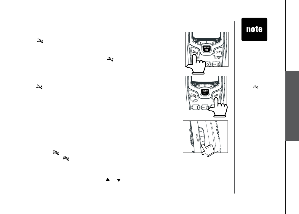
Making calls
• Press (or SPEAKER) to use the handset speakerphone feature),
then dial the phone number.
-OR-
Dial the phone number rst, then press
• Press
OFF to end your call or place the handset in its base or
charger.
Answering calls
• Press , SPEAKER or any dialing keys.
• Press
OFF to end your call or place the handset into its base or
charger.
Adjust handset volume
The volume control is on the right side of the handset. During a call,
press the VOLUME + or - keys to adjust the listening volume to a
comfortable level. When you reach the maximum or minimum setting,
a double beep will sound.
Flash function
When you subscribe to call waiting service from your telephone
company, press to switch to the new call when you receive a call
waiting signal. Press again to switch back to the original call.
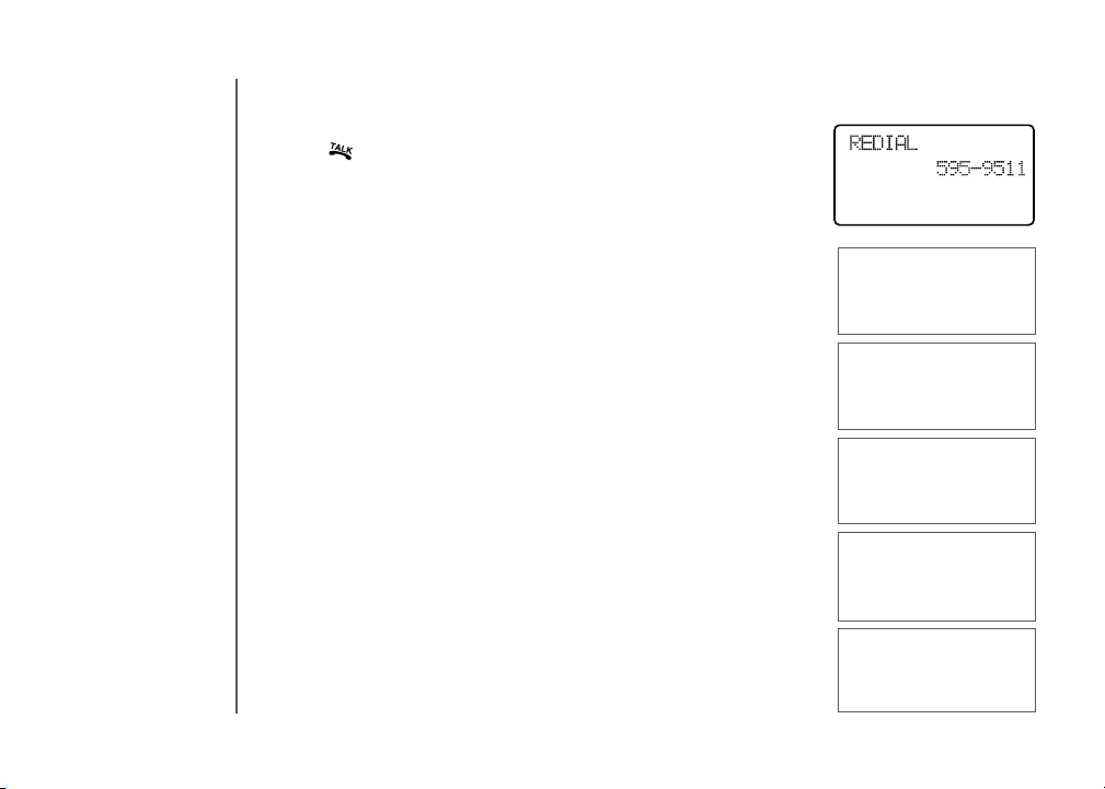
Redial
• Press REDIAL/PAUSE to display the last telephone number dialed
from the handset (up to 32 digits). Use or or REDAIL button to
scroll through the last ve numbers dialed. When the beginning or
(or SPEAKER).
• The procedure
to change
the volume is
the same for
the handset
earpiece,
speakerphone
and headset.
• Use
• If the redial
to
access phone
company
subscriber
services, as
described by
your provider.
memory is
empty, and
REDIAL is
pressed, a
double beep will
sound.
Basic operation
www.vtechphones.com
13
Page 14
Handset operation
the end of the redial list is reached, a double beep will sound.
• Press
• Press
hear a conrmation beep.
• To exit the redial review list, Press
Mute
• During a call, press the M UTE/REMOVE key to disable the
microphone. The other person on the call will not be able to hear
you. The screen will display MUTED briey:
or SPEAKER to dial the displayed number.
MUTE/REMOVE to delete the displayed number. You’ll
OFF.
PHONE 00:00:15
MUTED
MUTE
14
• Pr es s
MU TE/R EMOVE again to return to normal two -way
conversation.
MICROPHONE ON will display briey.
Intercom call
• Press INT on the originating handset (HS1).
•
INTERCOM TO: will show on the screen.
• Select the handset number you wish to establish an intercom
connection. (We’ll use handset number 2 for this example). The
display will show CALLING HANDSET 2.
• Handset 2 shows CALLING HANDSET 1.
• Press
• Press
INT, SPEAKER, TALK, or any dialing key on HS2 to pick
up the call and the display will change to INTERCOM.
INT, OFF, or place HS1 back into its base or charger to end
the call.
www.vtechphones.com
PHONE 00:00:15
MICROPHONE ON
INTERCOM TO:
CALLING
HANDSET 2
INTERCOM
Page 15

Handset operation
If the destination handset is in use, cannot be reached or turned
off, the display on the originating handset will show UNABLE TO
CALL TRY AGAIN.
INTERCOM ENDED
Call forward
An external call can be forwarded or transferred from one handset
(HS1) to another (HS2).
• While on an external call, you can forward the call to HS2 by
pressing and holding INTERCOM. HS1 will display FORWARD
TO: you should then input the number of the handset you wish
to forward the call to.
• HS2 will show
• Press
If the forwarded call is not answered within 30 seconds, the
external call will be returned to HS1 and the display will show
CALL BACK and ring for 30 seconds. If the returned call is not
answered within 30 seconds, it will end automatically.
INCOMING CALL and ring.
/FLASH on HS2 to answer the call.
www.vtechphones.com
UNABLE TO CALL
TRY AGAIN
Basic operation
CALL FORWARDED
15
Page 16

• For the FIND
HANDSET
function to work,
the system
handsets need
to be in idle (off)
mode.
16
Handset operation
Call transfer
• While on an external call, any system handset (HS1) can transfer the call to another system handset
(HS2) by pressing INT. The external call is put on hold automatically. Then select the handset
number to be transferred.
• HS2 will ring and the screen will show
• Pick up the intercom call on HS2 by pressing
• An intercom call is established and HS1 can communicate with HS2 prior to the external call being
transferred.
If the transferred call is not answered within 100 seconds, the external call will be returned to HS1
and the screen will show CALL BACK.
CALL TRANSFERRED will briey display on HS1.
Conference call
It is possible to establish a conference call between two handsets and
the external line.
While one handset is already connected to the external line, the other
handset can join the call by pressing . A conference call will be
immediately established, both handsets will show:
Find handset
• To locate a misplaced handset, press FIND HANDSET on the base to
page all system handsets.
• To end the page at the base, press
• To end the page at the handset, press
key (0-9, *, #).
Voice mail
If you subscribe to voice mail service provided by your telephone company,
you can receive voice mail messages from callers. When you have a new
voice mail, the screen will display NEW VOICE MAIL, and the voice mail
indicator will ash.
On how to access your voice mail, contact your local telephone company
for further instruction.
www.vtechphones.com
HS1 IS CALLING.
/FLASH.
FIND HANDSET again.
, SPEAKER, or any dial pad
PHONE 00:00:25
** PAGING **
HANDSET 1
NEW VOICE MAIL
Page 17

Telephone directory
Your phone can store up to 50 numbers with names in the directory. Each directory location can
hold up to 32 digits for the number and 16 characters for the name. Only one handset can access
the directory at a time. NOT AVAILABLE AT THIS TIME will be displayed if you try to access the
director y when another handset is already using the directory
Store a new entry
• Press MENU.
• With
DIRECTORY selected, press SEL.
• Press
• You will be prompted to
to enter the number you wish to store in the directory. Press the
MUTE/REMOVE key to backspace and make corrections. Press
SEL.
• You will then be prompted to
to spell the name. Press SEL.
• You’ll hear a conrmation tone, and the new directory entry will
display briey.
•
If the directory is full, the handset will display LIST FULL.
to select STORE. Press SEL.
ENTER NUMBER. Use the dialing keys
ENTER NAME. Use the dialing keys
>STORE
REVIEW
ENTER NUMBER
800-595-9511_
ENTER NAME
_
LIST FULL
• All handsets
share a common
directory which
is stored in the
base. Entries
inserted into
one handset are
available for all
handsets, and
if one deletes a
directory entry,
it will disappear
from all handsets.
• While entering
numbers,
press and hold
REDIAL/PAUSE
to add pauses if
necessary.
• If there is a
duplicated
number in
directory, the
display will show
ALREADY
SAVED.
Basic operation
www.vtechphones.com
17
Page 18

• If you wish to
store a number
from redial
memory into the
directory, press
REDIAL/PAUSE
then or
to scroll to the
desired redial
number from
memory. Press
SEL.
Telephone directory
Characters by number
Pressing any par ticular key causes different characters to be displayed in the following order:
Key
1 2 3 4 5 6 7 8 9
1 # ‘ , - . &
1
A B C 2 a b c
2
D E F 3 d e f
3
G H I 4 g h i
4
J K L 5 j k l
5
M N O 6 m n o
6
P Q R S 7 p q r s
7
T U V 8 t u v
8
W X Y Z 9 w x y z
9
0
0
? ! / ( )
space
#
Characters by number of key presses
@
18
www.vtechphones.com
Page 19

Telephone directory
Review/dial from the directory
• Press MENU, when DIRECTORY is displayed, press SEL. With
REVIEW in the rst line, press SEL.
- OR -
With the handset in idle, press to enter the directory review mode.
The rst directory entry will be displayed.
• Scroll through the directory
character of the name to be searched (using the digit keys). Continue
navigating using the or scroll keys, until you reach the entr y
to be dialed.
• Press
or SPEAKER to dial the number.
Edit a directory entry
• Follow the steps in Review/dial from the directory (above) to reach
the entry to be edited.
• Press
• Press
SEL to enter number edit mode.
MUTE/REMOVE to backspace and delete numbers, or press
CID or DIR to move the cursor to the number you wish to change.
Then re-enter the correct number(s) by pressing the dialing keys (0-9).
Press and hold REDIAL/PAUSE to add pauses if necessary.
entries using and or enter the rst
>DIRECTORY
CALL LOG
EDIT NUMBER
800-595-9511_
• When reviewing
the phonebook,
the second line
of the display
will show the
number, up to
16 digits. For
numbers longer
than 16 digits,
only the rst 13
digits will be
shown. Press
or # to scroll the
phone number
to see the
additional digits.
• If there are no
entries in the
directory, when
it is accessed,
DIRECTORY
EMPT Y will
display.
Basic operation
*
www.vtechphones.com
19
Page 20

Telephone directory
• Press SEL.
20
• Press
• Press
MUTE/REMOVE to backspace and use the digit keys to
enter the correct name.
SEL. You’ll hear a conrmation tone.
Delete a directory entry
• Follow the steps in Review/dial from the directory (page 19)
to reach the entry to be deleted.
• Press
• The handset will then advance to the next entr y, if any.
MUTE/REMOVE to delete the entry. A conrmation tone
will sound.
www.vtechphones.com
EDIT NAME
VTech Com_
Page 21

Caller ID
Caller ID - call waiting ID
Your phone is capable of displaying the number of the calling party before you answer the phone
(Caller ID or CID). If the number is already in the directory, the name of the caller will also be displayed.
It is also capable of displaying CID information in conjunction with a call waiting alert signal (call
waiting caller ID). With call waiting caller ID, the CID data is displayed so you can decide whether
to answer the incoming call, or continue with your current conversation. Your phone can hold up to
50 CID entries.
NOTES ABOUT CALLER ID & CALL WAITING CALLER ID These are subscription services,
provided by most regional telephone service providers. You must subscribe to these services to
get the benets of these features. If you do not subscribe to CID services, you can still use your
phone and the other features it offers.
Due to regional incompatibilities, CID information may not be available for every incoming call. In
addition, the calling parties may intentionally block their name and/or phone number from being
sent.
• As new CID/call waiting ID records are received, your handset
displays will alert you to the new CID records, for example:
VTECH
5 MISSED CALLS
• If you answer
a call before
the information
appears on the
screen, it will not
be in the caller
ID log.
• Press
• The
OFF any
time to exit caller
ID log.
NEW icon
in the lower left
corner indicates
the call has
not yet been
reviewed.
Basic operation
• After you review all new CID records, the
turned off and the screen will show:
NEW call indicator will be
www.vtechphones.com
VTECH
21
Page 22

22
Caller ID
• If the call log is full, the oldest entry is deleted to make room
for the new call. If the call log is empty when you try to enter to
call log review, the following message is displayed:
Review caller ID
You can review the CID records via the menu as described below,
or by pressing while in idle, and the handset moves directly
to CID review.
• In idle mode, press
• Press
• Press
When the beginning or the end of the call log is reached, a
double beep will sound.
to scroll to the CALL LOG option.
SEL. Use and to scroll through the call log entries.
Store caller ID
• Follow the steps in Review caller ID (above) to scroll to the
record to be stored.
• To view alternate dialing sequences, press the
The screen will scroll through the various dialing options (1 +
area code + number, area code + number, 1 + number, number
only). Press SEL to store the displayed number. The various
dialing options are:
• If the CID record contains both name and number, the CID will
be stored after pressing SEL.
• If the CID record does not contain a name, you will be prompted
to EDIT NAME and the screen will show:
MENU.
# key repeatedly.
www.vtechphones.com
CALL LOG EMPTY
>CALL LOG
RINGER VOLUME
595-9511
1-595-9511
800-595-9511
1-800-595-9511
EDIT NAME
VTech Com_
Page 23

Caller ID
• If the CID record does not contain a number, you will be
prompted to EDIT NUMBER, and the screen will show:
• A conrmation beep will sound and the screen will display:
• If both name and number are missing, for example, as in a
private listing, the request will be rejected with the message:
EDIT NUMBER
800-595-9511_
SAVED
UNABLE TO SAVE
Basic operation
• If the number already exists in the director y, the entry will not
be stored, and the screen will show:
• If the directory is full, the screen will show:
www.vtechphones.com
A L R E A D Y
SAVED
LIST FULL
23
Page 24

Caller ID
Dial from caller ID
• Follow the steps in Review caller ID (page 22) to scroll to the
entry to be dialed.
• To change how the number will be dialed, press
The screen will scroll through the dialing options:
Press
/FLASH or SPEAKER key to dial the number.
Delete caller ID
• Follow the steps in Review caller ID (page 22) to scroll to the
record to be deleted.
# repeatedly.
595-9511
1-595-9511
800-595-9511
1-800-595-9511
24
• Press the
A conrmation beep will sound and the previous CID record
will be displayed on the screen.
• To delete all the CID records, press and hold the
REMOVE key. The screen will ask if you want to DELETE
ALL CALLS? Press SEL to conrm. Press OFF to return to
the CID record previously displayed.
MUTE/REMOVE key to delete the desired record.
MUTE/
www.vtechphones.com
Page 25

Handset settings
Ringer volume
• From the idle (off) mode, press SEL then or until RINGER VOLUME
is shown.
• Press
SEL. The current ringer volume will be shown:
• Press
- OR -
• From idle (off) mode, press the
• Press
Ring tone
• From the idle (off) mode, press SEL then or until RINGER TONE
• Press
• Press
Key tone
• From the idle (off) mode, press SEL then or to KEY TONE.
• Press
• When the desired option is shown, press
and or enter a digit (0 through 6) to the desired ringer volume. The
current ring tone will play and the volume bar is increased or decreased each
time the setting is adjusted. At the lowest setting the display will show:
+/- volume control keys on the side
of the handset to directly enter the RINGER VOLUME menu.
and to the desired ringer volume.
is displayed.
SEL. You can then use or or enter a digit (0 through 9) to
sample the ring tone.
SEL to conrm.
SEL. The current setting will be shown. Press or to scroll to
ON or OFF. When set to ON, the handset will emit a beep whenever a
key is pressed.
SEL.
• The handset will
not ring when a
call comes in if
ringer volume is
set at the lowest
setting.
Basic operation
>KEY TONE
LANGUAGE
www.vtechphones.com
25
Page 26

• The clear voice
mail function only
cancels the voice
mail indicator on
the screen of the
handset.
•
When the phone
is set for pulse
dial mode, it is
possible to switch
to temporary tone
mode during an
outgoing call by
pressing *TONE.
Once pressed, tone
will be used for rest
of the call. After you
hang up, the phone
will return to pulse
dialing for the next
call.
Handset settings
• From idle (off) mode, press SEL then or to HANDSET
NAME.
• Pre ss
• Press
NOTE: The characters are entered in the same way as for the
telephone directory, see the table on page 18.
• Press
Language (preset to English)
• Fr o m the id l e (of f ) mode, press ME N U then or to
• Press
• Press
Clear voice mail
• From the idle (off) mode, press MENU then or to CLR
• Press SEL.
• Press
Dial type (preset to tone)
• From idle (off) mode, press MENU then or to DIAL TYPE.
• Press
• Press
SE L. The displ ay will show the curre nt set ting, for
example:
DELETE to backspace then enter the desired name.
SEL to conrm.
LANGUAGE.
SEL. Press or to select from English, Spanish or
French.
SEL to conrm.
VOICE MAIL.
SEL again to conrm or press OFF to exit.
SEL then or to scroll to TONE or PULSE.
SEL to conrm.
HANDSET NAME
Kitchen_
LANGUAGE
ENGLISH
>CLR VOICE MAIL
DIAL TYPE
TURN INDICATOR
OFF?
>DIAL TYPE
DIRECTORY
DIAL TYPE
PULSE
26
www.vtechphones.com
Page 27

Headset operation
Headset
You can use this telephone handsfree when you install
any VTech 2.5 mm headset, purchased separately.
Plug the headset into the jack located on the left side of
the handset (under the small rubber ap). Do not force the
connection, but make sure the plug ts securely.
Operating range
T h is c or d l e s s t e le p h on e o p er a t e s w i th i n
th e ma x i mum p owe r a ll o w e d b y th e F e d er a l
Commu nications Commission (FCC). Even so, t his
handset and base can communicate only over a certain
distance - which can var y with the locations of the base
and handset, the weather, and the construction of your
home or ofce.
If you receive a call while you are out of range, the
handset might not ring or if it does ring, the call might not
connect well when you press TALK. Move closer to the
base, then press TALK to answer the call.
If you move out of range during a phone conversation, you
might hear noise or interference. To improve reception,
move closer to the base.
If you move out of range without pressing OFF, the phone
will be left off the hook. To hang up properly, walk back
into range, periodically pressing OFF.
• To purchase a
headset, visit us on
the web at www.
vtechphones.com
or call VTech
Customer Service
at 1-800-595-
9511. In Canada,
contact VTech
Telecommunications
Canada Ltd. at www.
vtechcanada.com or
1-800-267-7377.
Basic operation
www.vtechphones.com
27
Page 28

• If you repeatedly
get a low battery
indicator, even
after charging
overnight, the
battery should be
replaced.
• To reduce the
risk of re or
injury to persons
or damage to the
telephone, read
and follow these
instructions
carefully.
• Charge the
battery provided
or identied
for use with
this product in
accordance with
the instructions
and limitations
specied in this
user’s manual.
Batteries
Battery care and performance
After the battery is fully charged, you can expect the following performance:
Operation Operating time
While in use (talking) up to 7 hours
While not in use (standby*) up to 3 days
* Handset is off the base unit or charger but not in use.
• The batter y needs charging when:
— A new battery is installed in the handset.
— The phone beeps twice every ve seconds.
— The screen displays
• Pla ce the han dset in th e base so the
charged in about 16 hours.
• You can keep the battery fully charged by returning the handset to the base or charger after each use.
Replace the handset battery
1. Remove the batter y compartment cover on the handset by
pressing on the indentation and sliding the cover downward.
2. Lift out the old battery and disconnect.
3. Align the two holes in the new battery’s plug with the socket pins,
and snap the plug into place. Snap the battery in the compartment,
as described in Installation, on page 5.
4. Replace the cover by sliding it up into place.
5. The new battery must be fully charged before using the phone.
Place the handset in the base or charger and allow it to charge for at
least 16 hours the rst charge. The telephone might operate before
that, but for best performance, let the battery charge fully.
LOW BATTERY and the low batter y icon.
CH ARG E ligh t turn s on. The bat ter y is usu all y full y
28
www.vtechphones.com
Page 29

Additional Information
Troubleshooting
If you have difculty operating your phone, the suggestions below should solve the problem. If you still have difculty after
trying these suggestions, call VTech Communications at 1-800-595-9511. In Canada, call VTech Telecommunications
Canada Ltd. at 1-800-267-7377.
Problem Suggestion
My phone doesn’t
work at all.
I cannot get a dial
tone.
• Make sure the power cord is plugged in.
• Make sure the telephone line cord is plugged rmly into the base unit and the telephone wall
jack.
• Disconnect the AC adaptor for a few minutes, and then reconnect it.
• Charge the battery in the handset for at least 16 hours. For optimum daily performance, return
the handset to its base when not in use.
• Reset the base. Unplug the unit’s electrical power. Wait for 15 seconds then plug it back in.
Allow up to one minute for the handset and base to reset.
• You may need to purchase a new battery, please refer to the
manual.
• Try all the suggestions above.
• Move the handset closer to the base. You might have moved out of range.
• Your line cord might be malfunctioning. Try installing a new line cord.
• If the previous suggestions don’t work, disconnect the base unit from the telephone jack and
connect a different phone. If there is no dial tone on that phone either, the problem is in your
wiring or local service. Contact your local telephone company.
Batteries section of this user’s
Additional information
www.vtechphones.com
29
Page 30

Troubleshooting
Problem Suggestion
I cannot dial out. • Make sure you have a dial tone before dialing. The handset may take a second or two to nd the
UNABLE TO
CALL TRY
AGAIN displays
on my handset.
The battery does
not hold a charge.
30
base and produce a dial tone. This is normal. Wait an extra second before dialing.
• Make sure your phone is set to the correct dial mode for the type of service that you have (pulse or
touch tone). Refer to the dial mode section of this user’s manual.
• If the other phones in your home are having the issue, the problem is in your wiring or local service.
Contact your local telephone company.
•
Eliminate any background noise. Noise from a television, radio or other appliance may cause the phone
not to dial out properly. If you cannot eliminate the background noise, rst try muting the handset before
dialing, or dialing from another room in your home with less background noise.
• Move the handset closer to the base. You might have moved out of range.
• If the handset is in its base and the charging light does not light, refer to the
section in this troubleshooting guide.
• Reset the base. Unplug the unit’s electrical power. Wait for 15 seconds then plug it back in. Allow
up to one minute for the handset and base to reset.
• Other electronic products can cause interference with your cordless phone. Try installing your
phone as far away from these types of electronic devices as possible: wireless routers, radios,
radio towers, pager towers, cell phones, intercoms, room monitors, televisions, personal computers,
kitchen appliances and other cordless phones.
• Charge the battery in the handset for 16 hours. For optimum daily performance, return the handset
to its base when not in use.
• You may need to purchase a new battery, please refer to the
manual.
• Your phone might be malfunctioning. Please refer to the
further instruction.
Warranty section of this user’s manual for
Batteries section of this user’s
Charge light is off
www.vtechphones.com
Page 31

Troubleshooting
Problem Suggestion
If you subscribe to
DSL service
I get noise, static,
or weak signal
even when I’m
near the base.
• If you hear noise during conversations and/or your caller ID features aren’t functioning properly,
install a noise lter to the telephone line between the base unit and the telephone line jack. Contact
your DSL provider to obtain a noise lter.
• Other cordless phones and 802.11 wireless routers that are used for home computer networks both
use internal radios to communicate. The radios may interfere with one another. You can improve
the performance of your cordless phones and your router by: a. positioning your new phone
as far away as possible from any other existing cordless telephone system that is already installed
in your home to avoid the two systems interfering with each other.
b. positioning your telephone base as far as possible from your router, computer or any other
computer devices.
c. selecting channels four through 10 for your router (refer to your router’s user manual for more
information).
• Other electronic products can cause interference with your cordless phone. Try installing your
phone as far away from these types of electronic devices as possible: wireless routers, radios,
radio towers, pager towers, cell phones, intercoms, room monitors, televisions, personal computers,
kitchen appliances and other cordless phones.
• Microwaves operate on the same frequency as your phone. It is normal to experience static on
your phone while the microwave is running. Do not install this phone in the same outlet or near the
microwave.
• If your phone is plugged in with a modem or surge protector, plug the phone (or modem/surge
protector) into a different location. If this solves the problem, re-locate your phone or modem farther
apart from one another, or use a different surge protector.
• Relocate your phone to a higher location. The phone will likely get better reception not installed in
a low area.
• If the other phones in your home are having the issue, the problem is in your wiring or local service.
Contact your local telephone company (charges may apply.)
www.vtechphones.com
Additional information
31
Page 32

Troubleshooting
Problem Suggestion
I hear other calls while
using my phone.
My handset does not
ring when I receive
a call.
• Disconnect your base unit from the telephone jack, and plug in a regular telephone. If you
still hear other calls, the problem is probably in your wiring or local service. Call your local
telephone company.
• Make sure you have the ringer activated. Refer to the section(s) on ringer selection in this
user’s manual.
• Make sure the telephone line cord is plugged rmly into the base unit and the telephone jack.
Make sure the power cord is plugged in.
• You may be too far from the base unit.
• Charge the battery in the handset for 16 hours. For optimum daily performance, return the
handset to its base when not in use.
• You may have too many extension phones on your telephone line to allow all of them to ring.
Try unplugging some of the other phones.
• The layout of your home or ofce might be limiting the operating range. Try moving the base
to another location, preferably on an upper oor.
• If the other phones in your home are having the issue, the problem is in your wiring or local
service. Contact your local telephone company (charges may apply.)
• Test a working phone at the phone jack. If another phone has the same problem, the problem
is the phone jack. Contact your local telephone company (charges may apply.)
• Other electronic products can cause interference with your cordless phone. Try installing
your phone as far away from these types of electronic devices as possible: wireless routers,
radios, radio towers, pager towers, cell phones, intercoms, room monitors, televisions, personal
computers, kitchen appliances and other cordless phones
• Your line cord might be malfunctioning. Try installing a new line cord.
32
www.vtechphones.com
Page 33

Troubleshooting
Problem Suggestion
My calls fade or cut in
and out while I’m using
my handset.
The charge light is off. • Clean the handset and base charging contact each month using a pencil eraser or cloth.
• Other electronic products can cause inter ference with your cordless phone. Try installing
your phone as far away from these types of electronic devices as possible: wireless routers,
radios, radio towers, pager towers, cell phones, intercoms, room monitors, televisions, personal
computers, kitchen appliances and other cordless phones
• Microwaves operate on the same frequency as your phone. It is normal to experience static
on your phone while the microwave is running. Do not install this phone in the same outlet or
near the microwave.
• If your phone is plugged in with a modem or surge protector, plug the phone (or modem/surge
protector) into a different location. If this solves the problem, re-locate your phone or modem
farther apart from one another, or use a different surge protector.
• Relocate your phone to a higher location. The phone will get better reception not installed in
a low area.
• If the other phones in your home are having the issue, the problem is in your wiring or local
service.
• Make sure the power and line cords are plugged in correctly and rmly.
• Reset the base. Unplug the unit’s electrical power. Wait for 15 seconds then plug it back in.
Allow up to one minute for the handset and base to reset.
• Your phone might be malfunctioning. Please refer to the
for further instruction.
Warranty section of this user’s manual
Additional information
www.vtechphones.com
33
Page 34

Troubleshooting
Problem Suggestion
My Caller ID isn’t
working.
Common cure for
electronic equipment.
• Caller ID is a subscription service. You must subscribe to this ser vice for this feature to work
on your phone.
• Your caller must be calling from an area that supports caller ID.
• Both you and your caller’s telephone companies must use caller ID compatible equipment.
If the unit does not seem to be responding normally, then try putting the handset in its base. If it
does not seem to respond, do the following (in the order listed):
1. Disconnect the power to the base.
2. Disconnect the handset battery, and spare battery, if applicable.
3. Wait a few minutes.
4. Connect power to the base.
5. Re-install the battery(ies).
6. Wait for the handset to re-establish its link with the base. To be safe, allow up to one minute
for this to take place.
34
www.vtechphones.com
Page 35

Maintenance
Taking care o f your telephone
Your cordless telephone contains sophisticated electronic parts, so it must be treated with care.
Avoid rough treatment
Place the handset down gently. Save the original packing materials to protect your telephone if you ever need to ship it.
Avoid water
Your telephone can be damaged if it gets wet. Do not use the handset outdoors in the rain, or handle it with wet hands. Do not install your base unit near a sink, bathtub or shower.
Electrical storms
Electrical storms can sometimes cause power surges harmful to electronic equipment. For your own safety, use caution when using electric appliances during storms.
Cleaning your telephone
Your telephone has a durable plastic casing that should retain its luster for many years. Clean it only with a soft cloth slightly dampened with water or a mild soap. Do not use excess water or
cleaning solvents of any kind.
Remember that electrical appliances can cause serious injury if used when you are wet or standing in water. If your base unit should fall into water, DO NOT RETRIEVE IT UNTIL YOU
UNPLUG THE POWER CORD AND TELEPHONE LINE CORDS FROM THE WALL. Then pull the unit out by the unplugged cords.
Warranty
What does this limited warranty cover?
• Th e manufact urer of this VTech produ ct, VTech Communic ations, war rants to the holder o f a valid proo f of purcha se (“Con sumer” or “ you”) that the pro duct and a ll access ories provided by
VTech in the sa les package (“Pro duct ”) are free fr om materia l defects i n material and workm anship, pur suant to the followi ng terms and c onditions, whe n install ed and used n ormally and in
accord ance wit h operatio n instructions . This limi ted warrant y extends only to th e Consume r for Produc ts purchased and u sed in the Un ited State s of Americ a.
What will VTech Communications do if the Product is not free from material defects in materials and workmanship during the limited warranty period (“Materially Defective Product”)?
• During th e limited warranty p eriod, VTech’s authori zed serv ice repre sentative will repa ir or replace at VTech’s opti on, without charg e, a Material ly Defect ive Produc t. If we repair this
product , we may use new or refurbis hed replacement p arts. If we c hoose to replace t his produ ct, we may rep lace it with a new or refur bished produc t of the same or s imilar design. V Tech
will return r epaired or replace ment products to you i n working condit ion. VTech wil l retain defective p arts, mo dules, or equipmen t. Repair or replace ment of Product, at V Tech’s opti on, is
your exclusi ve remedy. You should expect t he repair or replace ment to take approxim ately 30 days .
How long is the limited warranty period?
• The limite d warranty perio d for the prod uct extends for ONE (1) YEAR fr om the date of purchas e if we repair or replac e a Material ly Defect ive Produc t under the terms of th is limited
warranty. Thi s limited warranty a lso applies to repai red or replacement P roduct s for a perio d of either (a) 90 d ays from the date the rep aired or rep lacemen t Product i s shipped to you or (b)
the time rem aining on the origi nal one-ye ar warrant y; whichever is long er.
What is not covered by this limited warranty?
This limited warranty does not cover
1. Product that h as been subjected t o misuse, ac cident, shippi ng or other phy sical da mage, impr oper inst allation, abnorm al operati on or handling, neg lect, inu ndation, re, water or ot her liquid
intrusio n; or
2. Product that h as been damaged due t o repair, alter ation or mo dicati on by anyone other than an a uthorize d service repres entative of VTech; or
3. Produ ct to the ext ent that the p roblem experien ced is caus ed by signal condit ions, net work reliabilit y or cable or antenna sys tems; or
4. Product to th e extent tha t the probl em is caused by use wit h non-VTech ele ctrical acces sories; or
Additional information
www.vtechphones.com
35
Page 36

Warranty
5. Produ ct whose wa rranty/q uality s tickers, Pr oduct serial num bers plate s or electronic ser ial numbers have bee n removed, al tered or rendered ill egible; or
6. Produ ct purcha sed, used, servi ced, or shipped for r epair from outside t he United States, or us ed for commercial o r institu tional pur poses (includi ng but not lim ited to Prod ucts use d for rental
purpos es ); or
7. Product retu rned wit hout valid p roof of pur chase (see 2 be low); or
8. C harges for i nstallation or set u p, adjustm ent of custo mer contr ols, and in stallati on or repair of systems o utside th e unit.
How do you get warranty service?
• To obtain warrant y service in the Un ited States of Ameri ca, call 1-800- 595-9511 for instruct ions rega rding whe re to return t he Produc t. Before calling fo r servi ce, please c heck the user’s
manual. A ch eck of the Pro duct controls an d features may save you a ser vice call.
• Exc ept as provided by ap plicabl e law, you assume the risk o f loss or damage duri ng transi t and trans portat ion and are re sponsible for del ivery or ha ndling charges in curred in the trans port
of Produc t (s) to the ser vice locatio n. VTech will ret urn repaired or repl aced product und er this limited warra nty to you, tr ansportation , deliver y or handling charg es prepaid. VTech assu mes
no risk for d amage or loss of the Pro duct in tr ansit.
• If the Prod uct failur e is not covered by this li mited warr anty, or proof o f purchas e does not meet the term s of this limited warra nty, VTech will notify yo u and will req uest that you author ize the
cost of repa ir prior to an y furthe r repair act ivity. You must pay for the cos t of repair an d return shi pping costs for the r epair of Products t hat are not cove red by this limited war ranty.
What must you return with the Product to get warranty service?
1. Retur n the entire o riginal package a nd content s including the Pro duct to the VTech ser vice loc ation along with a de scripti on of the malfuncti on or difculty ;
2. In clude “valid pro of of purchase” (sale s receipt) i dentif ying the Pr oduct pur chased (Product m odel) and the date of pur chase or receipt; a nd
3. Provide y our name, co mplete and c orrect mailing ad dress, and telepho ne number.
Other Limitations
• This warran ty is the co mplete and exclusiv e agreemen t between yo u and VTech. It superse des all othe r written or oral com munications rel ated to this Pr oduct. V Tech pro vides no ot her
warrantie s for this pro duct. The warrant y exclusively desc ribes all of VTech’s resp onsibil ities reg arding th e produc t. There are n o other express warra nties. No o ne is author ized to make
modic ations to th is limited w arranty a nd you should not rely o n any such mo dicati on.
St ate Law Righ ts: This warr anty gives you spec ic legal rights , and you may als o have other ri ghts whic h vary from state to st ate.
Lim itations: Impli ed warranties, including tho se of tness for a par ticular purp ose and merch antabil ity (an u nwritten warra nty th at the p roduct is t for ord inary u se) are limited t o one ye ar from
date of purc hase. Some states do n ot allow lim itations o n how long an implied wa rranty l asts, so th e above limitation may n ot apply to you.
• In no event shal l VTech be liab le for any ind irect, s pecial, i ncident al, consequenti al, or simil ar damages ( includ ing, but not l imited to lo st prots or revenue, in ability to use the pr oduct, or
other asso ciated equipment , the cost of substit ute equipment, and c laims by third part ies) resulting from th e use of this produc t. Some sta tes do not all ow the exclusion or lim itation of
inciden tal or cons equential damage s, so the above limitat ion or exclusion may not a pply to you.
36
www.vtechphones.com
Page 37

Important safety instructions
When using your telephone equipment, basic safety precautions should always be followed to reduce the risk of re, electric shock and injury, including the following:
1. Read and understand all instructions.
2. Follow all warnings and instructions marked on the product.
3. Unplug this product from the wall outlet before cleaning. Do not use liquid or aerosol cleaners. Use a damp cloth for cleaning.
4. Do not use this product near water (for example, near a bath tub, kitchen sink or swimming pool).
5. Do not place this product on an unstable surface, such as a table, shelf or stand. The product may fall, causing serious damage.
6. Slots and openings in the back or bottom of the base unit and handset are provided for venti lation. T o pro tect them from over heating, these openings must not be blocked by placing the
product on a soft surface such as a bed, sofa or rug. This product should never be placed near or over a radiator or heat register. This product should not be placed in any area where proper
ventilation is not provided.
7. This product should be operated only from the type of power source indicated on the marking label. If you are not sure of the type of power supply in your home, consult your dealer or local power
company.
8. Do not allow anything to rest on the power cord. Do not install this product where the cord may have anyone walking on it.
9. Never push objects of any kind into this product through slots in the base or handset as they may touch dangerous voltage points or short out parts that could result in a risk of re or electric shock.
Never spill liquid of any kind on the product.
10. To reduce the risk of electric shock, do not disassemble this product, but take it to an authorized service facility. Opening or removing parts of the base or handset other than specied access
doors may expose you to dangerous voltages or other risk s. I ncorrec t reass embling can ca use ele ctric s hock wh en the pro duct is subsequently used.
11. Do not overload wall outlets and extension cords as this can result in the risk of re or electric shock.
12. Unplug this product from the wall outlet and refer servicing to an authorized service facility under the
following conditions:
A. When the power supply cord or plug is damaged or frayed.
B. If liquid has been spilled onto the product.
C. If the product has been exposed to rain or water.
D. If the product does not operate normally by following the operating instructions. Adjust only those controls that are covered by the operating instructions, as improper adjustment of
other controls may result in damage and often requires extensive work by an authorized technician to restore the product to normal o peration.
E. If the pr oduct has been dropped and th e base and/or handset has been damaged.
F. If the product exhibits a distinct change in performance.
13. Avoid using a telephone (other than cordless) during an electrical storm. There is a remote risk of electric shock from lightning.
14. Do not use the telephone to report a gas leak in the vicinity of the leak.
15. Only p ut the handset of your telephone next to your ear when it is in normal talk.
SAVE THESE INSTRUCTIONS
Additional information
www.vtechphones.com
37
Page 38

FCC, ACTA and IC regulations
FCC Part 15
This equipment has been tested and found to comply with the requirements for a Class B digital device under Part 15 of the Federal Communications Commission (FCC) rules. These requirements
are intended to provide reasonable protection against harmful interference in a residential installation. This equipment generates, uses and can radiate radio frequency energy and, if not installed and
used in accordance with the instructions, may cause harmful interference to radio communications. However, there is no guarantee that interference will not occur in a particular installation. If this
equipment does cause harmful interference to radio or television reception, which can be determined by turning the equipment off and on, the user is encouraged to try to correct the interference by
one or more of the following measures:
* Reorient or relocate the receiving antenna.
* Increase the separation between the equipment and receiver.
* Connect the equipment into an outlet on a circuit different from that to which the receiver is connected.
* Consult the dealer or an experienced radio/TV technician for help.
Changes or modications to this equipment not expressly approved by the party responsible for compliance could void the user’s authority to operate the equipment.
To ensure safety of users, the FCC has established criteria for the amount of radio frequency energy that can be safely absorbed by a user or bystander according to the intended usage of the product.
This product has been tested and found to comply with the FCC criteria. The handset may be safely held against the ear of the user. The base unit shall be installed and used such that parts of the user’s
body other than the hands are maintained at a distance of approximately 20 cm (8 inches) or more. If you choose to use a clipping device, please make sure to only use the supplied VTech belt clip.
FCC Part 68 and ACTA
This equipment complies with Part 68 of the FCC rules and with technical requirements adopted by the Administrative Council for Terminal Attachments (ACTA). The label on the back or bottom of this
equipment contains, among other things, a product identier in the format US:AAAEQ##TXXXX. This identier must be provided to your local telephone company upon request.
The plug and jack used to connect this equipment to premises wiring and the telephone network must comply with applicable Part 68 rules and technical requirements adopted by ACTA. A compliant
telephone cord and modular plug is provided with this product. It is designed to be connected to a compatible modular jack that is also compliant. An RJ11 jack should normally be used for connecting
to a single line and an RJ14 jack for two lines. See Installation Instructions in the user’s manual.
The Ringer Equivalence Number (REN) is used to determine how many devices you may connect to your telepho ne line and still have them ring when you are called. The REN for this product is
encoded as the 6th and 7th characters following the US: in the product identier (e.g., if ## is 03, the REN is 0.3). In most, but not all areas, the sum of all RENs should be ve (5.0) or less. For more
information, please contact your local telephone company.
This equipment may not be used with Party Lines. If you have specially wired alarm dialing equipment connected to your telephone line, ensure the connection of this equipment does not disable your
alarm equipment. If you have questions about what will disable alarm equipment, consult your telephone company or a qualied installer.
If this equipment is malfunctioning, it must be unplugged from the modular jack until the problem has been corrected. Repairs to this telephone equipment can only be made by the manufacturer or its
authorized agents. For repair procedures, follow the instructions outlined under the Limited Warranty.
If this equipment is causing harm to the telephone network, the telephone company may temporarily discontinue your telephone service. The telephone company is required to notify you before
interrupting service. If advance notice is not practical, you will be notied as soon as possible. You will be given the opportunity to correct the problem and the telephone company is required to inform
you of your right to le a complaint with the FCC. Your telephone company may make changes in its facilities, equipment, operation, or procedures that could affect the proper functioning of this product.
The telephone company is required to notify you if such changes are planned.
38
www.vtechphones.com
Page 39

FCC, ACTA and IC regulations
If this product is equipped with a corded or cordless handset, it is hearing aid compatible.
If this product has memory dialing locations, you may choose to store emergency telephone numbers (e.g., police, re, medical) in these locations. If you do store or test emergency numbers, please:
* Remain on the line and briey explain the reason for the call before hanging up.
* Perform such activities in off-peak hours, such as early morning or late evening.
Industry Canada
This equipment complies with regulations RSS210 and CS-03 of Industry Canada. Operation is subject to the following two conditions: (1) this device may not cause interference, and (2) this device
must accept any interference, including interference that may cause undesired operation of the device.
The term “IC:” before the certication/registration number only signies that the Industry Canada technical specications were met.
The Ringer Equivalence Number (REN) for this terminal equipment is 0.1. The REN is an indication of the maximum number of devices allowed to be connected to a telephone interface. The termination
on an interface may consist of any combination of devices subject only to the requirement that the sum of the RENs of all the devices does not exceed ve.
The RBRC® Seal
The RBRC® Seal on the nickel -metal-hydrid e batt ery indi cates that VTech Com munications, Inc. is vo luntarily parti cipating in an in dustry program to co llect and
recycle t hese batteries at th e end of their useful li ves, when taken out of ser vice within the U nited States and Cana da.
The RB RC® prog ram pro vides a conve nient a lternative to placing used nickel-metal -hydride bat teries into the tra sh or municipal was te,whi ch may be illegal in
your area.
VTech’s par ticipation in RBRC® makes it easy for you t o drop off the spe nt batte ry at local retaile rs par ticipating in the RBRC® progr am or at autho rized V Tech
produc t s ervice centers. Please ca ll 1-800- 8-BATTERYT M for information on Ni -MH batt ery recycling and d isposal bans/res tricti ons in your area. VTech’s
involveme nt in this program is p art of its c ommitme nt to protecting our en vironme nt and cons erving natural re sources .
RBRC® is a regis tered t radema rk of Rechargea ble Battery Re cycling Corpora tion.
Additional information
www.vtechphones.com
39
Page 40

Technical specications
Enhanced 5.8GHz technology–your
2.4GHz technologies, providing enhanced performance over standard cordless telephones.
Frequency Control Crystal controlled PLL synthesizer
phone operates on a dual band transmission that combines the best of 5.8GHz and
Transmit Frequency Base: 5725-5850 MHz
Receive Frequency Base: 2400-2483.5 MHz
Channels 95
Nominal Effective Range Maximum power allowed by the FCC and IC. Actual operating range may vary
Size Handset: 150.3mm X 50.3mm X 37.3mm
Weight Handset: 120.4 grams Base: 175 grams (with wall mount)
Power Requirements Handset: 600mAH Ni-MH batter y
Memory Director y: 50 memory locations, up to 32 digits, 16 characters per location
40
Handset: 2400-2483.5 MHz
Handset: 5725-5850 MHz
according to environmental conditions at the time of use.
Base: 122.8mm X 108.7mm X 62.3mm
Charger: 80mm X 89.3mm X 51mm
Charger: 64.4 grams
Base: 9V DC @ 400mA
Charger: 9V DC @ 200mA
Caller ID: 50 memory locations
www.vtechphones.com
Page 41

Index
A
Adjust handset volume 13
Answering calls 13
B
Base LEDs 12
Base unit layout 11
Batteries 28
Belt clip 8
C
Caller ID 21–24
Caller ID - call waiting ID 21
Characters by number 18
Check battery indicator 7
Check for dial tone 8
Choose location 5
Clear voice mail 26
Conference call 16
Connect power to base unit/
chargers 6
Connect to phone 6
D
Delete a directory entry 20
Delete caller ID 24
Dial from caller ID 24
Director y 17
DSL (internet) 9
E
Edit a directory entr y 19
F
FCC, ACTA and IC regulations 38
Find handset 16
Flash function 13
H
Handset icons 12
Handset layout 10
Handset LEDs 12
Handset name 41
Handset operation 13–16
Handset settings 25 –26
Headset 27
Headset operation 27
I
If you subscribe to DSL service 8
Important safety instructions 37
Installation 5–9
Installing handset battery 5
Internet 9
K
Key tone 25
L
Language 26
M
Maintenance 35
Making calls 13
Mute 14
N
Noise lter 9
O
Operating range 27
P
Parts check list 4
R
Redial 14
Replace handset battery 28
www vtechphones com
41
Page 42

Index
S
Store a new entry 17
Store caller ID 22
T
Technical specications 40
Telephone directory 17–20
The RBRC® Seal
Troubleshooting 29
V
Voice mail service 16
Volume 13, 25
W
Wall mounting (optional) 9
Warranty 35
42
www.vtechphones.com
Page 43

VTECH TELECOMMUNICATION LTD.
A member of THE VTECH GROUP OF COMPANIES.
Distributed in the U.S.A. by VTech Communications, Inc. Beaverton, Oregon
Distributed in Canada by VTech Telecommunications Canada Ltd., Richmond, B.C.
Copyright ©2006 for VTECH TELECOMMUNICATIONS LTD.
Printed in China.
91-000781-020-000
Page 44

Models: i6734/6735
User’s Manual
w w w . v t e c h p h o n e s . c o m
 Loading...