

Page 1
Owners Manual
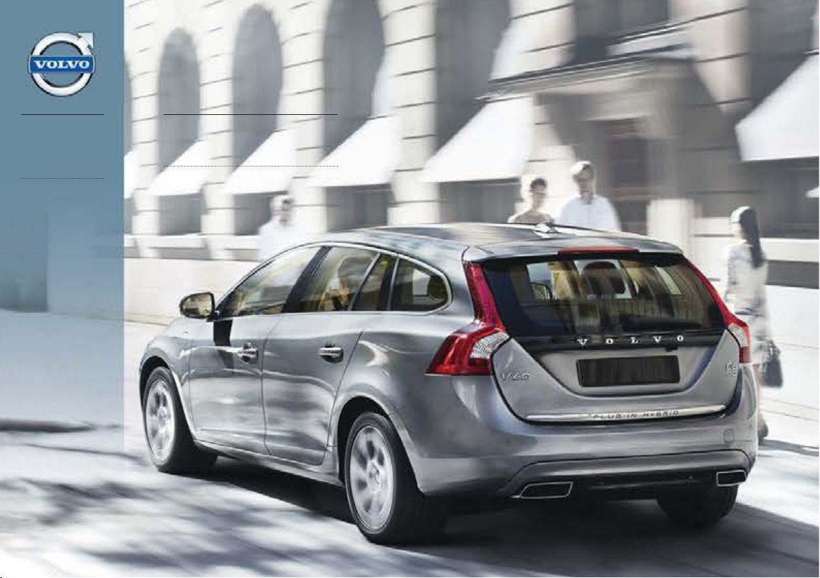
V60 PLUG-IN
HYBRID
WEB EDITION
Page 2

Page 3

DEAR VOLVO OWNER
THANK YOU FOR CHOOSING VOLVO
We hope you will enjoy many years of driving
pleasure in your Volvo. The car has been
designed for the safety and comfort of you and
your passengers. Volvo is one of the safest cars in
the world. Your Volvo has also been designed to
satisfy all current safety and environmental
requirements.
In order to increase your enjoyment of the car, we
recommend that you familiarise yourself with the
equipment, instructions and maintenance information contained in this owner's manual.
Page 4
Table of contents
2
* Option/accessory, for more information, see Introduction.
00
00 Introduction
Important information................................. 6
Volvo and the environment....................... 10
Plug-in hybrid - overview.......................... 13
01
01 Safety
Seatbelts .................................................. 18
Airbags...................................................... 21
Activating/deactivating the airbag*........... 24
Side airbags (SIPS bags) ......................... 26
Inflatable Curtain (IC) ............................... 27
WHIPS ...................................................... 28
When the systems deploy ........................ 30
Safety mode.............................................. 31
Child safety............................................... 32
02
02 Locks and alarm
Remote control key/key blade.................. 46
Privacy locking*......................................... 52
Battery replacement, remote control
key/PCC*................................................... 54
Keyless drive*............................................ 56
Locking/unlocking..................................... 60
Child safety locks...................................... 65
Alarm*....................................................... 66
Page 5
Table of contents
* Option/accessory, for more information, see Introduction.
3
03
03 Your driving environment
Instruments and controls.......................... 70
Volvo Sensus ........................................... 83
Key positions............................................ 84
Seats......................................................... 86
Steering wheel.......................................... 91
Lighting..................................................... 93
Wipers and washing................................ 103
Windows, rearview and door mirrors...... 106
Compass*............................................... 111
Power sunroof*....................................... 113
Alcolock*................................................. 115
Starting the engine.................................. 119
Starting the engine – external battery..... 121
Drive systems ......................................... 123
Gearboxes............................................... 128
All Wheel Drive - AWD............................ 132
Foot brake............................................... 133
Parking brake.......................................... 136
HomeLink® *............................................ 140
04
04 Driver support
DSTC – Stability and traction control sys-
tem.......................................................... 146
Road sign information - RSI*.................. 148
Speed limiter........................................... 151
Cruise control*........................................ 153
Adaptive cruise control*.......................... 155
Distance Warning*.................................. 166
City Safety™........................................... 169
Collision Warning with Auto Brake &
Pedestrian Protection*............................ 175
Driver Alert System*................................ 183
Driver Alert System - DAC*..................... 184
Driver Alert System - LDW*..................... 188
Park assist syst*...................................... 191
Park assist camera*................................ 194
BLIS*....................................................... 197
05
05 Comfort and driving pleasure
Menus and messages............................. 204
Menu source MY CAR............................ 206
Climate control........................................ 214
Preconditioning the car .......................... 225
Heater .................................................... 231
Trip computer......................................... 233
Adapting driving characteristics............. 238
Comfort inside the passenger compart-
ment........................................................ 239
Page 6

Table of contents
4
* Option/accessory, for more information, see Introduction.
06
06 Infotainment system
General information on infotainment...... 246
Radio....................................................... 257
Media player........................................... 264
External audio source via AUX/USB*
input........................................................ 268
Media Bluetooth®* ................................. 271
Bluetooth® handsfree*............................ 274
Voice recognition* mobile phone............ 283
TV*........................................................... 287
Remote control* ..................................... 291
07
07 During your journey
Recommendations during driving........... 296
Refuelling................................................ 300
Fuel......................................................... 301
Charging - hybrid battery ....................... 304
Loading................................................... 312
Cargo area.............................................. 314
Driving with a trailer................................ 317
Towing and recovery.............................. 323
08
08 Wheels and tyres
General ................................................... 328
Changing wheels ................................... 333
Tyre pressure ......................................... 336
Warning triangle and first-aid kit*............ 337
Emergency puncture repair (TMK) ......... 338
Page 7
Table of contents
5
09
09 Maintenance and service
Engine compartment............................... 346
Lamps..................................................... 353
Wiper blades and washer fluid................ 359
Battery..................................................... 362
Fuses...................................................... 365
Car care.................................................. 379
10
10 Specifications
Type designations................................... 388
Dimensions and weights......................... 390
Engine specifications.............................. 393
Engine oil................................................ 394
Fluids and lubricants............................... 396
Fuel......................................................... 398
Wheel and tyres, dimensions and pres-
sure ........................................................ 399
Electrical system..................................... 401
Type approval......................................... 402
Licenses.................................................. 407
Symbols in the display............................ 410
11
11 Alphabetical Index
Alphabetical Index.................................. 414
Page 8
Introduction
Important information
6
* Option/accessory, for more information, see Introduction.
Reading the Owner's Manual
Introduction
A good way of getting to know your new car
is to read the owner's manual, ideally before
your first journey. This will give you the
opportunity to familiarise yourself with new
functions, to see how best to handle the car
in different situations, and to make the best
use of all the car's features. Please pay attention to the safety instructions contained in the
manual.
The specifications, design features and illustrations in this owner's manual are not binding. We reserve the right to make modifications without prior notice.
©
Volvo Car Corporation
IMPORTANT
Do not remove this manual from the car should a problem arise then the information required about where and how to seek
professional help would be missing.
Option
All types of option/accessory are marked with
an asterisk*.
In addition to standard equipment, this manual also describes options (factory fitted
equipment) and certain accessories (retrofitted extra equipment).
The equipment described in the owner's
manual is not available in all cars - they have
different equipment depending on adaptations for the needs of different markets and
national or local laws and regulations.
In the event of uncertainty over what is standard or an option/accessory, contact a Volvo
dealer.
Special texts
WARNING
Warning texts advise of a risk of personal
injury.
IMPORTANT
Important texts advise of a risk of material
damage.
NOTE
NOTE texts give advice or tips that facilitate the use of features and functions for
example.
Footnote
There is footnote information in the owner's
manual that is located at the bottom of the
page. This information is an addition to the
text that it refers to via a number. If the footnote refers to text in a table then letters are
used instead of numbers for referral.
Message texts
Text messages can be shown in the combined instrument panel and in the screen.
These text messages are highlighted in the
owner's manual by means of the text being
slightly larger and printed in grey. Examples
of this are in menu texts and message texts in
the screen (e.g.
Audio settings).
Decals
The car contains different types of decal
which are designed to convey important
information in a simple and clear manner. The
decals in the car have the following descending degree of importance for the warning/
information.
Page 9

Introduction
Important information
7
Warning for personal injury
G031590
Black ISO symbols on yellow warning field,
white text/image on black message field.
Used to indicate the presence of danger
which, if the warning is ignored, may result in
serious personal injury or fatality.
Risk of property damage
G031592
White ISO symbols and white text/image on
black or blue warning field and message field.
Used to indicate the presence of danger
which, if the warning is ignored, may result in
damage to property.
Information
G031593
White ISO symbols and white text/image on
black message field.
NOTE
The labels shown in the owner's manual
are not provided as exact reproductions of
those in the car. The purpose is to show
their approximate appearance and location
in the car. The information that applies to
your car in particular is available on the
label in question in your car.
Page 10
Introduction
Important information
8
Procedure lists
Procedures where action must be taken in a
certain sequence are numbered in the
owner's manual.
When there is a series of illustrations for
step-by-step instructions each step is
numbered in the same way as the corresponding illustration.
There are numbered lists with letters
adjacent to the series of illustrations
where the order of the instructions is not
significant.
Arrows appear numbered and unnumbered and are used to illustrate a movement.
Arrows with letters are used to clarify a
movement when the reciprocal order is of
no relevance.
If there is no series of illustrations for step-bystep instructions then the different steps are
numbered with normal numbers.
Position lists
Red circles containing a number are used
in overview images where different components are pointed out. The number
recurs in the position list featured in connection with the illustration that describes
the item.
Bulleted lists
A bulleted list is used when there is a list of
points in the owner's manual.
Example:
•
Coolant
•
Engine oil
Images
The manual's images are sometimes schematic and may deviate from the car's appearance depending on equipment level and market.
To be continued
}} This symbol is located furthest down to
the right when a section continues on the following page.
Recording data
Your vehicle contains a number of computers
whose function is to continuously check and
monitor the vehicle's operation and functionality. Some of the computers can record
information during normal driving if they
detect an error. In addition, information is
recorded in the event of a collision or incident. Parts of the recorded information are
required so that technicians can diagnose
and rectify faults in the vehicle during servicing and maintenance and so that Volvo can
fulfil legal requirements and other regulations.
In addition to this, the information is used for
research purposes by Volvo in order to continually develop quality and safety, as the
information can contribute to a better understanding of the factors that cause accidents
and injuries. The information includes details
of the status and functionality of various systems and modules in the vehicle with regard
to engine, throttle, steering and brake systems, amongst other things. This information
may include details regarding the way the
driver drives the vehicle, such as vehicle
speed, brake and accelerator pedal use,
steering wheel movement and whether or not
the driver and passengers have used their
seatbelts. For the reasons given this information may be stored in the vehicle's computers
for a certain length of time, but also as a
result of a collision or incident. This information may be stored by Volvo as long as it can
help to further develop and further enhance
safety and quality and as long as there are
legal requirements and other regulations that
Volvo needs to consider.
Volvo will not contribute to the above-described information being disclosed to third parties without the vehicle owner's consent.
However, due to national legislation and regulations Volvo may be required to disclose
such information to authorities such as police
Page 11
Introduction
Important information
* Option/accessory, for more information, see Introduction.
9
authorities, or others who may assert a legal
right to have access to it.
To be able to read and interpret the information recorded by the computers in the vehicle
requires special technical equipment that
Volvo, and workshops that have entered into
agreements with Volvo, have access to. Volvo
is responsible that the information, which is
transferred to Volvo during servicing and
maintenance, is stored and handled in a
secure manner and that the handling complies with applicable legal requirements. For
further information - contact a Volvo dealer.
Accessories and extra equipment
The incorrect connection and installation of
accessories can negatively affect the car's
electrical system. Certain accessories only
function when their associated software is
installed in the car's computer system. Volvo
therefore recommends that you always contact an authorised Volvo workshop before
installing accessories which are connected to
or affect the electrical system.
Change of ownership for cars with
Volvo On Call*
Volvo On Call is a supplemental service that
consists of safety, security and comfort services. If the car has Volvo On Call and there is
a change of owner, it is very important that
these services are discontinued so that the
former owner cannot access the services in
the car. Contact an authorised Volvo dealer in
the event of a change of ownership.
Information on the Internet
At www.volvocars.com there is further information concerning your car.
A QR code reader is required to read the QR
code, which is available as a supplemental
program for several mobile phones. The QR
code reader can be downloaded from App
Store or Google Play.
QR code
Page 12
Introduction
Volvo and the environment
10
Volvo Cars' environmental philosophy
G000000
Environmental care is one of Volvo Car Corporation's core values which influence all
operations. We also believe that our customers share our consideration for the environment.
Your Volvo complies with strict international
environmental standards and is also manufactured in one of the cleanest and most
resource-efficient plants in the world. Volvo
Car Corporation has global ISO certification,
which includes the environmental standard
ISO 14001 covering all factories and several
of our other units. We also set requirements
for our partners so that they work systematically with environmental issues.
Fuel consumption
Volvo cars have competitive fuel consumption in each of their respective classes. Lower
fuel consumption generally results in lower
emission of the greenhouse gas, carbon dioxide.
It is possible for the driver to influence fuel
consumption. For more information read
under the heading, Reducing environmental
impact.
Efficient emission control
Your Volvo is manufactured following the
concept "Clean inside and out" – a concept
that encompasses a clean interior environment as well as highly efficient emission control. In many cases the exhaust emissions are
well below the applicable standards.
Clean air in the passenger
compartment
A passenger compartment filter prevents dust
and pollen from entering the passenger compartment via the air intake.
Page 13

Introduction
Volvo and the environment
* Option/accessory, for more information, see Introduction.
11
A sophisticated air quality system, IAQS*
(Interior Air Quality System) ensures that the
incoming air is cleaner than the air in the traffic outside.
The system consists of an electronic sensor
and a carbon filter. The incoming air is monitored continuously and if there is an increase
in the level of certain unhealthy gases such as
carbon monoxide then the air intake is
closed. Such a situation may arise in heavy
traffic, queues and tunnels for example.
The entry of nitrous oxides, ground-level
ozone and hydrocarbons is prevented by the
carbon filter.
Interior
The interior of a Volvo is designed to be pleasant and comfortable, even for people with
contact allergies and for asthma sufferers.
Extreme attention has been given to choosing
environmentally-compatible materials.
Volvo workshops and the environment
Regular maintenance creates the conditions
for a long service life and low fuel consumption for your car. In this way you contribute to
a cleaner environment. When Volvo's workshops are entrusted with the service and
maintenance of your car it becomes part of
our system. Volvo makes clear demands
regarding the way in which our workshops
are designed in order to prevent spills and
discharges into the environment. Our workshop staff have the knowledge and the tools
required to guarantee good environmental
care.
Reducing environmental impact
You can easily help reduce environmental
impact - here are a few tips:
•
Avoid letting the engine idle - switch off
the engine when stationary for longer
periods. Pay attention to local regulations.
•
Drive economically - think ahead.
•
Perform service and maintenance in
accordance with the owner's manual's
instructions - follow the Service and Warranty Booklet's recommended intervals.
•
If the car is equipped with an engine
block heater*, use it before starting from
cold - it improves starting capacity and
reduces wear in cold weather and the
engine reaches normal operating temperature more quickly, which lowers consumption and reduces emissions.
•
High speed increases consumption considerably due to increased wind resistance - a doubling of speed increases
wind resistance 4 times.
•
Always dispose of environmentally hazardous waste, such as batteries and oils, in
an environmentally safe manner. Consult
a workshop in the event of uncertainty
about how this type of waste should be
discarded - an authorised Volvo workshop is recommended.
Following this advice can save money, the
planet's resources are saved, and the car's
durability is extended. For more information
and further advice, see the pages 208, 296
and 398.
Recycling
As a part of Volvo's environmental work, it is
important that the car is recycled in an environmentally sound manner. Almost all of the
car can be recycled. The last owner of the car
is therefore requested to contact a dealer for
referral to a certified/approved recycling
facility.
The owner's manual and the environment
The Forest Stewardship Council® symbol
shows that the paper pulp in this publication
comes from FSC® certified forests or other
controlled sources.
Page 14
Introduction
Volvo and the environment
12
Page 15
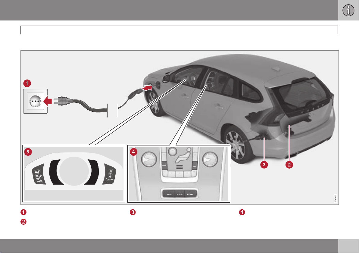
Overview
Introduction
Plug-in hybrid - overview
Charging the hybrid battery.
Hybrid battery.
Electric motor with drive on the rear
wheels.
Drive modes.
13
Page 16
Introduction
Plug-in hybrid - overview
14
Combined instrument panel with unique
information for the plug-in hybrid.
Important to know
WARNING
Remember that the car does not emit any
engine noise when it is only powered by
the electric motor and may therefore be
difficult to notice by children, pedestrians,
cyclists and animals. This applies in particular at low speeds, such as in car parks.
Hazard voltage
Several components in the car operate with
hazardous electrical voltage. Do not touch
anything that is not clearly described in this
owner's manual. Read more about the engine
compartment, see page 347.
WARNING
Orange cables marked with a high-voltage
decal must only be handled by qualified
personnel.
Driving the car
The car is driven as a completely normal car.
The electric motor drives the car mostly at
low speeds, the diesel engine at higher
speeds, as well as during more active driving.
Read more about recommendations during
driving, see page 296.
Drive modes
It is possible to set the car in different drive
modes while driving, e.g. electric operation
only or, when power is required, both electric
motor and diesel engine. The car calculates
an optimal combination of driveability, driving
experience, environmental impact and fuel
economy according to the drive mode
selected. Read more about drive modes,
page 123.
Combined instrument panel
Two fields in the combined instrument panel
show unique information for the V60 PLUG-IN
HYBRID; hybrid battery gauge (current energy
level), active drive mode, symbol that is illuminated when the diesel engine is operating,
Hybrid Guide as well as energy recovery.
Read more about the combined instrument
panel, see page 74.
Preconditioning
In order that the car should have optimal
function it is important that the hybrid battery
with associated electrical drive systems, as
well as the diesel engine and its drive systems, have the correct operating temperature.
Battery capacity is reduced considerably if
the battery is too cold or too hot. Preconditioning prepares the car's drive systems and
the passenger compartment before departure
so that both wear and energy needs during
the journey are reduced. Read more about
preconditioning, see page 225.
Charging the hybrid battery
The hybrid battery is the Lithium-ion type and
can be recharged in different ways. A charging cable with control unit can be connected
between the car and a 230V AC socket.
Charging time depends on charging current,
see page 304.
The electric motor is used as an engine brake
during light braking and the car's kinetic
energy is converted to electrical energy which
is used to charge the hybrid battery. Read
more about recovering the brake force
energy, see page 133.
Page 17

Introduction
Plug-in hybrid - overview
15
In addition, the diesel engine can charge the
electric motor's hybrid battery with a special
hazard voltage generator when the need arises, see drive system and drive modes, page
123.
Page 18

16
* Option/accessory, for more information, see Introduction.
Seatbelts ................................................................................................ 18
Airbags.................................................................................................... 21
Activating/deactivating the airbag*......................................................... 24
Side airbags (SIPS bags) ....................................................................... 26
Inflatable Curtain (IC) ............................................................................. 27
WHIPS .................................................................................................... 28
When the systems deploy ...................................................................... 30
Safety mode............................................................................................ 31
Child safety............................................................................................. 32
Page 19
SAFETY
Page 20
01 Safety
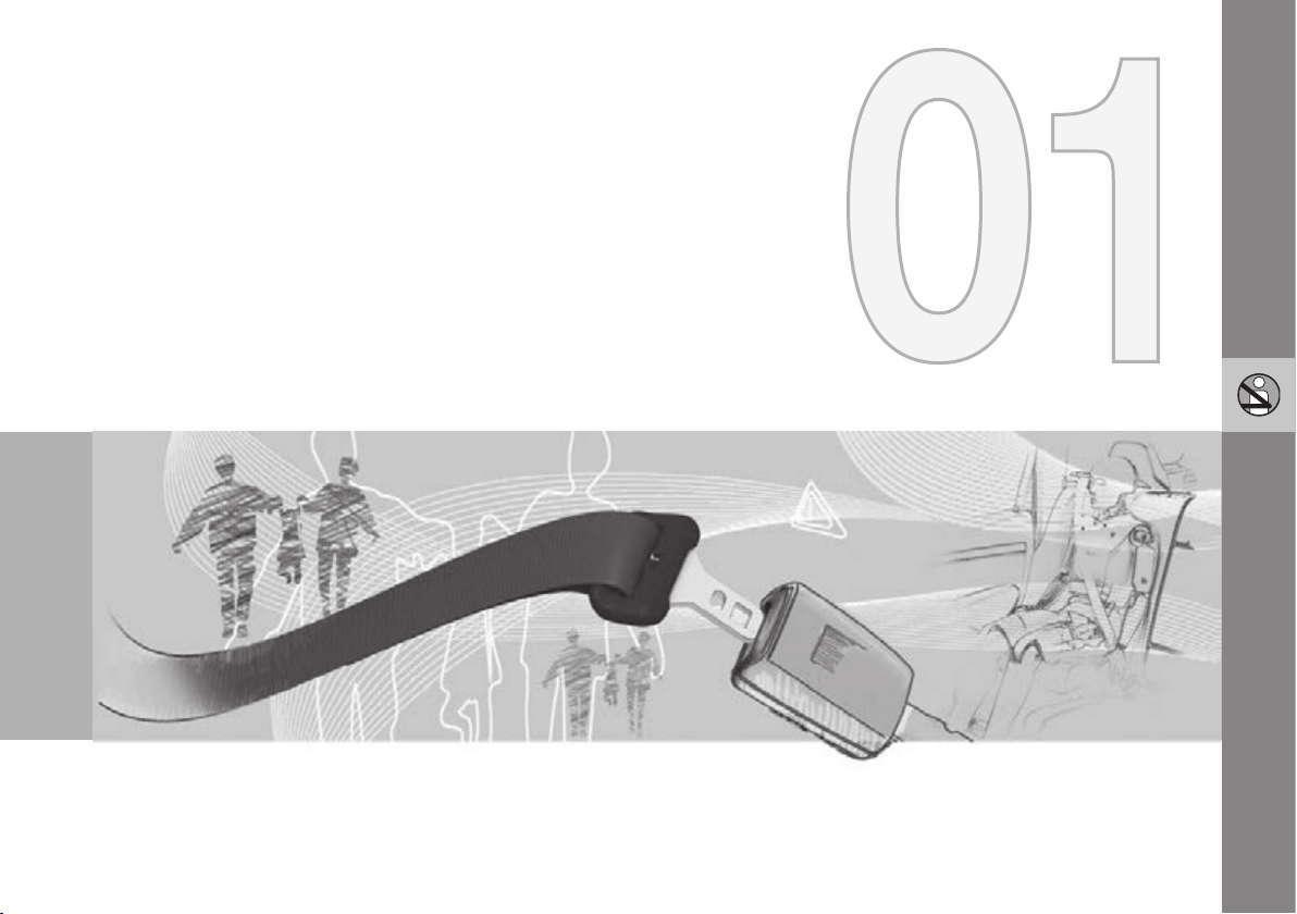
Seatbelts
01
18
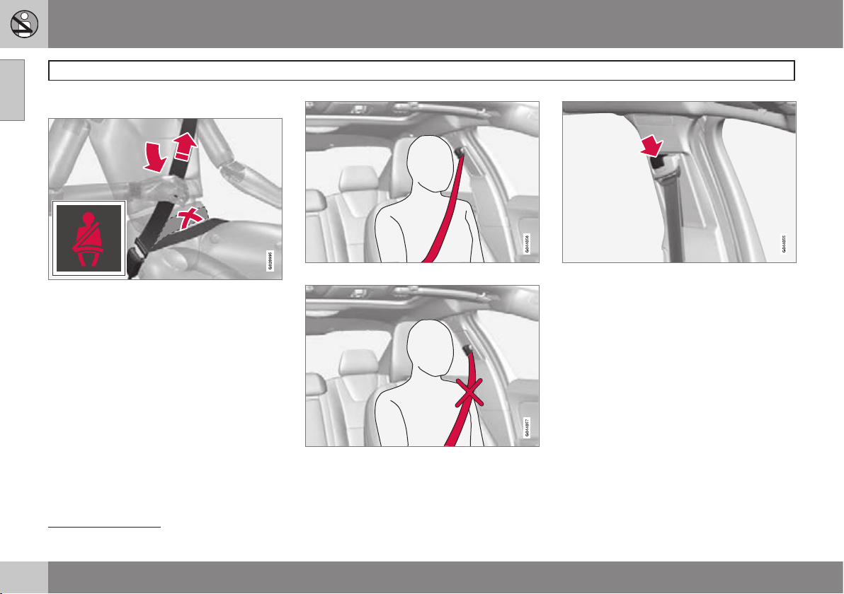
General information
Heavy braking can have serious consequences if the seatbelts are not used. Ensure that
all passengers use their seatbelts.
It is important that the seatbelt lies against
the body so it can provide maximum protection. Do not lean the backrest too far back.
The seatbelt is designed to protect in a normal seating position.
Putting on a seatbelt
Pull the belt out slowly and secure it by
pressing its locking tab into the seatbelt
buckle. A loud "click" indicates that the belt
has locked.
Correctly fitted seatbelt.
Incorrectly fitted seatbelt. The belt must rest on
the shoulder.
Seatbelt height adjustment. Press the button and
move the belt vertically. Position the belt as high
as possible without it chafing against your throat.
The buckles only fit the intended lock in the
rear seat1.
Releasing the seatbelt
Press the red button on the seatbelt buckle
and then let the belt retract. If the seatbelt
does not retract fully, feed it in by hand so
that it does not hang loose.
The seatbelt locks and cannot be withdrawn:
•
if it is pulled out too quickly
•
during braking and acceleration
•
if the car leans heavily.
1
Certain markets.
Page 21
01 Safety
Seatbelts
01
19
Make sure that you:
•
do not use clips or anything else that can
prevent the seatbelt from fitting properly
•
ensure that the seatbelt is not twisted or
caught on anything
•
the hip strap must be positioned low
down (not over the abdomen)
•
tension the hip strap over the lap by pulling the diagonal shoulder belt up towards
the shoulder.
WARNING
The seatbelts and airbags interact. If a
seatbelt is not used or is used incorrectly,
this may diminish the protection provided
by the airbag in the event of a collision.
WARNING
Each seatbelt is designed for only one person.
WARNING
Never modify or repair the seatbelts yourself. Volvo recommends that you contact
an authorised Volvo workshop.
If a seatbelt has been subjected to a major
load, such as in conjunction with a collision, the entire seatbelt must be replaced.
Some of the protective characteristics of
the seatbelt may have been lost, even if it
appears to be undamaged. In addition,
replace the seatbelt if the belt is worn or
damaged. The new seatbelt must be typeapproved and intended for installation in
the same position as the replaced seatbelt.
Seatbelts and pregnancy
G020998
The seatbelt should always be worn during
pregnancy. But it is crucial that it be worn in
the correct way. The diagonal section should
wrap over the shoulder then be routed
between the breasts and to the side of the
abdomen.
The lap section should lay flat over the thighs
and as low as possible under the abdomen. –
It must never be allowed to ride upward.
Remove the slack from the seatbelt and
ensure that it fits as close to the body as possible. In addition, check that there are no
twists in the seatbelt.
As the pregnancy progresses, pregnant drivers should adjust their seats and steering
wheel such that they can easily maintain control of the vehicle as they drive (which means
that they must be able to easily operate the
foot pedals and steering wheel). The aim
should be to position the seat with as large a
distance as possible between abdomen and
steering wheel.
Page 22
01 Safety
Seatbelts
01
20
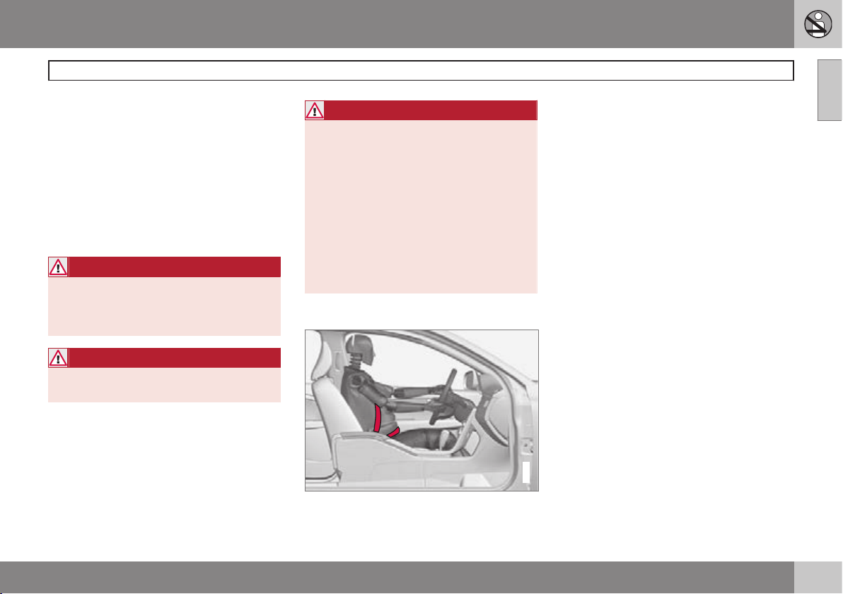
Seatbelt reminder
G017726
Unbelted occupants will be reminded to fasten their seatbelts by means of an audio and
visual reminder. The audible reminder is
speed dependent, and in some cases time
dependent. The visual reminder is located in
the roof console and in the combined instrument panel.
Child seats are not covered by the seatbelt
reminder system.
Rear seat
The seatbelt reminder in the rear seat has two
subfunctions:
•
Provides information on which seatbelts
are being used in the rear seat. A message appears in the combined instrument
panel when the seatbelts are in use, or if
one of the rear doors has been opened.
The message is acknowledged automatically after approximately 30 seconds driving or after pressing the indicator stalk's
OK button. If anyone is unbelted then the
message can only be acknowledged
manually by pressing the indicator stalk's
OK button.
•
Provides a warning if one of the rear seatbelts is unfastened during travel. This
warning takes the form of a message in
the combined instrument panel along with
the audio/visual signal. The warning stops
when the seatbelt is re-fastened, or it can
also be acknowledged manually by
pressing the OK button.
The combined instrument panel's information
display, see page 75, shows which seatbelts are in use. This information is always
available.
Certain markets
An acoustic signal and indicator lamp remind
the driver and front seat passenger to use a
seatbelt if either of them is not wearing one.
At low speed, the audible reminder will sound
for the first 6 seconds.
Seatbelt tensioner
All the seatbelts are equipped with belt tensioners. A mechanism in the seatbelt tensioner tightens the seatbelt in the event of a
sufficiently violent collision. The seatbelt then
provides more effective restraint for the occupants.
WARNING
Never insert the tongue of the passenger's
seatbelt into the buckle on the driver's
side. Always insert the tongue of the seatbelt into the buckle on the correct side. Do
not make any damages on seatbelts nor
insert any foreign objects into a buckle.
The seatbelts and buckles would then
possibly not function as intended in the
event of a collision. There is a risk of
serous injury.
Page 23
01 Safety
Warning symbol in combined
instrument panel
The warning symbol in the combined instrument panel illuminates when the remote control key is in key position II. The symbol
clears after approx. 6 seconds provided the
airbag system is fault-free.
WARNING
If the warning symbol for the airbag system remains illuminated or illuminates
while driving, it means that the airbag system does not have full functionality. The
symbol indicates a fault in the seatbelt tensioner system, SIPS, the IC system or
some other fault in the system. Volvo recommends that you contact an authorised
Volvo workshop immediately.
As well as the warning symbol, a message
may appear on the information display in
appropriate cases. If the warning symbol malfunctions, the warning triangle illuminates and
SRS airbag Service required or SRS
airbag Service urgent
play. Volvo recommends that you contact an
authorised Volvo workshop immediately.
appears in the dis-
Airbag system
Airbag system, left-hand drive car.
Airbag system, right-hand drive car.
The system consists of airbags and sensors.
A sufficiently violent collision trips the sensors
and the airbag(s) are inflated and become
hot. To cushion the impact, the airbag
deflates when compressed. When this
occurs, smoke escapes into the car. This is
completely normal. The entire process,
including inflation and deflation of the airbag,
G018665
occurs within tenths of a second.
WARNING
Volvo recommends that you contact an
authorised Volvo workshop for repair.
Defective work in the airbag system could
cause malfunction and result in serious
personal injury.
Airbags
01
G018666
21
Page 24
01 Safety
Airbags
01
22
NOTE
The detectors react differently depending
on the nature of the collision and whether
or not the seatbelts are fastened. Applies
to all belt positions.
It is therefore possible that only one (or
none) of the airbags may inflate in a collision. The detectors sense the force of the
collision on the vehicle and the action is
adapted accordingly so that one or more
airbags are deployed.
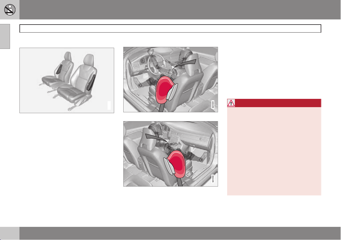
Airbag on the driver's side
The car has an airbag to supplement the protection afforded by the seatbelt on the driver's side. It is folded up into the centre of the
steering wheel. The steering wheel is marked
AIRBAG.
WARNING
The seatbelts and airbags interact. If a
seatbelt is not used or is used incorrectly,
this may diminish the protection provided
by the airbag in the event of a collision.
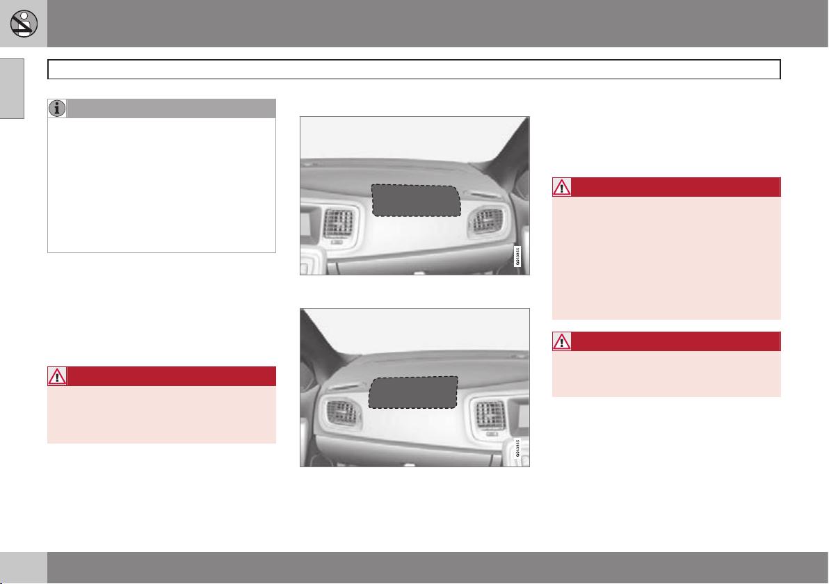
Passenger airbag
Location of the front passenger airbag in a lefthand drive car.
Location of the front passenger airbag in a righthand drive car.
The car has an airbag to supplement the protection afforded by the seatbelt on the passenger side. It is folded up into a compartment above the glovebox. Its cover panel is
marked AIRBAG.
WARNING
The seatbelts and airbags interact. If the
belt is not used or is used incorrectly, this
may diminish the protection provided by
the airbag in the event of a collision.
To minimise the risk of injury if the airbag
deploys, passengers must sit as upright as
possible with their feet on the floor and
backs against the backrest. Seatbelts
must be secured.
WARNING
Do not put objects in front of or above the
dashboard where the passenger airbag is
located.
Page 25
01 Safety
Airbags
01
23
WARNING
Never place a child in a child seat or on a
booster cushion in the front seat if the airbag is activated.
Never allow anybody to stand or sit in front
of the front passenger seat.
No one shorter than 140 cm should ever
sit in the front passenger seat if the airbag
is activated.
Failure to follow the advice given above
can endanger life.
Page 26
01 Safety
Activating/deactivating the airbag*
01
24
* Option/accessory, for more information, see Introduction.
Key switch off - PACOS*
General information
The airbag for the front passenger seat can
be deactivated if the car is equipped with a
switch, PACOS (Passenger Airbag Cut Off
Switch). For information on how to activate/
deactivate, see under the heading Activating/
deactivating.
Key switch off/switch
The switch for the passenger airbag (PACOS)
is located on the passenger end of the instrument panel and is accessible when the passenger door is open (see under the heading
below, Activating/deactivating).
Check that the switch is in the required position. The remote control key's key blade
should be used to change position.
For information on the key blade, see
page 50.
WARNING
Failure to follow the advice given above
could endanger the life of passengers in
the car.
WARNING
If the car is equipped with a front passenger airbag, but does not have a PACOS
switch (Passenger Airbag Cut Off Switch),
then the airbag will always be activated.
WARNING
Never place a child in a child seat or on a
booster cushion in the front seat if the air-
bag is activated and the symbol in
the roof console is illuminated. Failure to
follow this advice could endanger the life
of the child.
WARNING
Do not allow anyone to sit in the front passenger seat if the message in the roof console (see page 25) indicates that the airbag is deactivated, and if the warning
symbol for the airbag system is also displayed in the combined instrument panel.
This indicates that there has been a severe
malfunction. Visit a workshop as soon as
possible. Volvo recommends that you contact an authorised Volvo workshop.
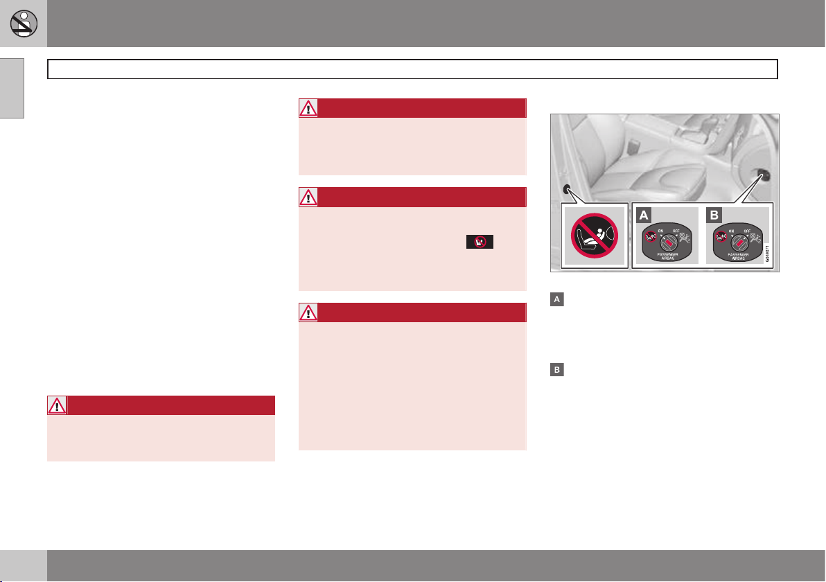
Activating/deactivating
Location of airbag label plus switch.
The airbag is activated. With the switch in
this position, persons taller than 140 cm
can sit in the front passenger seat, but
never children in a child seat or on a
booster cushion.
The airbag is deactivated. With the switch
in this position, children in a child seat or
on a booster cushion can sit in the front
passenger seat, but never persons taller
than 140 cm.
Page 27
01 Safety
Activating/deactivating the airbag*
01
* Option/accessory, for more information, see Introduction.
25
WARNING
Activated airbag (passenger seat):
Never place a child in a child seat or on a
booster cushion on the front passenger
seat when the airbag is activated. This
applies to everyone shorter than 140 cm.
Deactivated airbag (passenger seat):
No one taller than 140 cm should ever sit
in the front passenger seat when the airbag is deactivated.
Failure to follow the advice given above
can endanger life.
NOTE
When the remote control key is in key
position II the warning symbol for the airbag is shown in the combined instrument
panel for approx. 6 seconds (see page 21).
Following which, the indicator in the roof
console is illuminated showing the correct
status for the front passenger seat airbag.
For more information about the different
key positions for the remote control key,
see page 84.
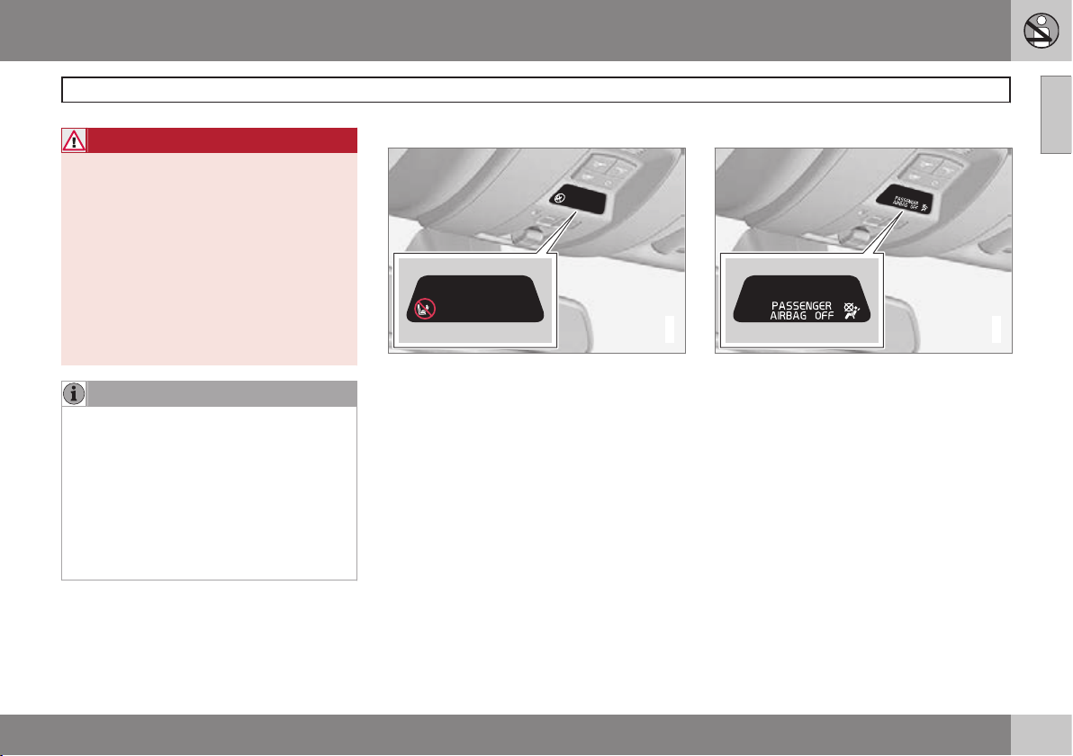
Activated airbag
G017800
Indicator showing that the passenger airbag is
activated.
A warning symbol in the roof console indicates that the airbag for the front passenger
seat is activated (see preceding illustration).
Deactivated airbag
2
2
G017724
Indicator showing that the passenger airbag is
deactivated.
A text message and a symbol in the roof console indicate that the airbag for the front passenger seat is deactivated (see preceding
illustration).
Page 28
01 Safety
Side airbags (SIPS bags)
01
26
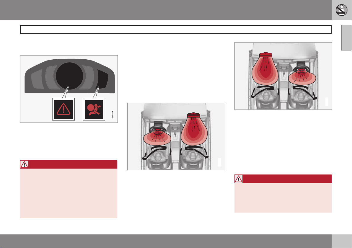
Side airbag
G032949
In a side impact collision a large proportion of
the collision force is transferred by the SIPS
(Side Impact Protection System) to beams,
pillars, the floor, the roof and other structural
parts of the body. The side airbags at the
driver's and front passenger seats protect the
chest area and the hip and are an important
part of the SIPS.
The SIPS bag system consists of two main
components, side airbag and sensors. The
side airbags are located in the front seat
backrests.
Location
Driver's seat, left-hand drive.
Front passenger seat, left-hand drive.
The SIPS bag system consists of side airbags
and sensors. A sufficiently violent collision
trips the sensors and the side airbags are
inflated. The airbag inflates between the
occupant and the door panel and thereby
cushions the initial impact. The airbag
deflates when compressed by the collision.
The side airbag is normally only deployed on
the side of the collision.
Child seats and side airbags
The protection provided by the car to children
seated in a child seat or on a booster cushion
is not diminished by the side airbag.
WARNING
•
Volvo recommends that repairs are
only carried out by an authorised Volvo
workshop. Defective work in the SIPSbag system could cause malfunction
and result in serious personal injury.
•
Do not put objects in the area between
the outside of the seat and the door
panel, since this area is required by
the side airbag.
•
Volvo recommends the use only of car
seat covers approved by Volvo. Other
seat covers may impede the operation
of the side airbags.
•
Side airbags are a supplement the
seatbelts. Always use a seatbelt.
Page 29
01 Safety
Properties
The inflatable curtain IC (Inflatable Curtain) is
a part of SIPS and the airbags. It is fitted in
the headlining along both sides of the roof
and protects the car's occupants sitting in the
outer seats. A sufficiently violent collision
trips the sensors and the inflatable curtain is
inflated. The inflatable curtain helps to prevent the driver and passengers from striking
their heads on the inside of the car during a
collision.
WARNING
Never hang or attach heavy items onto the
handles in the roof. The hook is only
designed for light clothing (not for solid
objects such as umbrellas for example).
Do not screw or install anything onto the
car's headlining, door pillars or side panels. This could compromise the intended
protection. Volvo recommends that you
only ever use Volvo genuine parts that are
approved for placement in these areas.
WARNING
Do not load the car higher than 50 mm
under the top edge of the door windows.
Otherwise, the intended protection of the
inflatable curtain, which is concealed in the
headlining, may be compromised.
WARNING
The inflatable curtain is a supplement to
the seatbelts.
Always use a seatbelt.
Inflatable Curtain (IC)
01
27
Page 30
01 Safety
WHIPS
01
28
Protection against whiplash injury – WHIPS
The whiplash protection system (WHIPS) consists of energy absorbing backrests and specially designed head restraints in the front
seats. The system is actuated by a rear-end
collision, where the angle and speed of the
collision, and the nature of the colliding vehicle all have an influence.
WARNING
The WHIPS system is a supplement to the
seatbelts. Always use a seatbelt.
Properties of the seat
When the WHIPS system is deployed, the
front seat backrests are lowered backward to
alter the seating position of the driver and
front seat passenger. This reduces the risk of
whiplash injury.
WARNING
Never modify or repair the seat or WHIPS
system yourself. Volvo recommends that
you contact an authorised Volvo workshop.
WHIPS system and child seats/booster
cushions
The protection provided by the car to children
seated in a child seat or on a booster cushion
is not diminished by the WHIPS system.
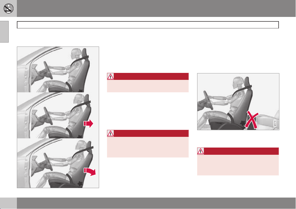
Correct seating position
For the best possible protection, the driver
and front seat passenger should sit in the
centre of the seat with as little space as possible between the head and the head
restraint.
Do not obstruct the WHIPS system
Do not leave any objects on the floor behind the
driver's seat/passenger seat that may prevent the
WHIPS system from functioning.
WARNING
Do not squeeze rigid objects between the
rear seat cushion and the front seat backrest. Make sure you do not to obstruct the
function of the WHIPS system.
Page 31

01 Safety
WHIPS
01
29
Do not place objects on the rear seat that may
prevent the WHIPS system from functioning.
WARNING
If a rear seat backrest is folded down, the
corresponding front seat must be moved
forward so that it does not touch the
folded backrest.
WARNING
If a seat has been subjected to extreme
forces, such as due to a rear-end collision,
the WHIPS system must be checked.
Volvo recommends that it is checked by
an authorised Volvo workshop.
Part of the WHIPS system's protective
capacity may have been lost even if the
seats appear to be undamaged.
Volvo recommends that you contact an
authorised Volvo workshop to have the
system checked even after a minor rearend collision.
Page 32

01 Safety
When the systems deploy
01
30
When the systems deploy
System Triggered
Seatbelt tensioner, front
seat
In the event of a frontal
collision, and/or sideimpact collision, and/or
rear-end collision
and/or overturning
Seatbelt tensioner, rear seat
In a frontal collision
and/or side-impact
accident and/or overturning
Airbags
(Steering wheel
and passenger
airbag)
In a frontal collision
A
Side airbags
(SIPS)
In a side-impact accident
A
Inflatable Curtain IC
In the event of a side
impact and/or overturning and/or some frontal
collisions
A
Whiplash protection WHIPS
In a rear-end collision
A
The bodywork of the car could be greatly deformed in a
collision without airbag deployment. A number of factors
such as the rigidity and weight of the object hit, the speed
of the car, the angle of the collision etc. affects how the
different safety systems of the car are activated.
If the airbags have deployed, the following is
recommended:
•
Recovering the car. Volvo recommends
that you have it conveyed to an authorised Volvo workshop. Do not drive with
deployed airbags.
•
Volvo recommends that you engage an
authorised Volvo workshop to handle the
replacement of components in the car's
safety systems.
•
Always contact a doctor.
NOTE
The airbags and belt tensioner system are
deployed only once during a collision.
WARNING
The airbag system's control module is
located in the centre console. If the centre
console is drenched with water or other
liquid, disconnect the cables to the starter
battery. Do not attempt to start the car
since the airbags may deploy. Recovering
the car. Volvo recommends that you have
it conveyed to an authorised Volvo workshop.
WARNING
Never drive with deployed airbags. They
can make steering difficult. Other safety
systems may also be damaged. The
smoke and dust created when the airbags
are deployed can cause skin and eye irritation/injury after intensive exposure. In case
of irritation, wash with cold water. The
rapid deployment sequence and airbag
fabric may cause friction and skin burns.
Page 33

01 Safety
Driving after a collision
If the car is involved in a collision, the text
Safety mode See manual may appear on
the information display. This means that the
car has reduced functionality. Safety mode is
a protective state that is enforced when the
collision may have damaged any of the car's
vital functions, such as the fuel lines, sensors
for one of the safety systems, or the brake
system.
Attempting to start the car
First, check that no fuel is leaking from the
car. There must be no smell of fuel either.
If everything seems normal and you have
checked for indications of fuel leakage, you
may attempt to start the car.
Remove the remote control key and open the
driver's door. If a message is now shown to
the effect that the ignition is on, press the
start button. Then close the door and reinsert
the remote control key. The car's electronics
will now try to reset themselves to normal
mode. Then try to start the car.
If the message
still shown on the display then the car must
not be driven or towed, but a vehicle recovery
service used instead, see page 324. Hidden
damage can make the car impossible to
manoeuvre during the journey, even if the car
seems driveable.
Safety mode See manual is
Moving the car
If Normal mode is shown after Safety mode
See manual
moved carefully out of a dangerous position.
Do not move the car further than necessary.
has been reset, the car can be
WARNING
Never attempt to repair your car or reset
the electronics yourself if the car has been
in safety mode. This could result in personal injury or the car not functioning as
normal. Volvo recommends that you
engage an authorised Volvo workshop to
check and restore the car to normal status
Safety mode See manual has been
after
displayed.
Safety mode
WARNING
Never, under any circumstances, attempt
to restart the car if it smells of fuel when
Safety mode See manual message
the
is displayed. Leave the car at once.
WARNING
If the car is in safety mode it must not be
towed. It must be transported from its
location. Volvo recommends that it is
transported to an authorised Volvo workshop.
01
31
Page 34

01 Safety
Child safety
01
32
Children should sit comfortably and safely
Volvo recommends that children travel in
rear-facing child seats until as late an age as
possible, at least until 3-4 years of age, and
then front-facing booster cushions/child seats
until up to 10 years of age.
The position of a child in the car and the
choice of equipment are dictated by the
child's weight and size, for more information,
see page 33.
NOTE
Regulations regarding the placement of
children in cars vary from country to country. Check what does apply.
Children of all ages and sizes must always sit
correctly secured in the car. Never allow a
child to sit on the knee of a passenger.
Volvo has child safety equipment (child seats,
booster cushions & attachment devices)
which is designed for your particular car.
Using Volvo's child safety equipment provides you with optimum conditions for your
child to travel safely in the car. Furthermore,
the child safety equipment fits and is easy to
use.
NOTE
In the event of questions when fitting child
safety products, contact the manufacturer
for clearer instructions.
Child seats
G020739
Child seats and airbags are not compatible.
NOTE
When using child safety products it is
important to read the installation instructions included.
WARNING
Do not secure the straps of the child seat
to the seat's horizontal adjustment bar,
springs or the rails and beams under the
seat. Sharp edges may damage the straps.
Look in the installation instructions for the
child seat for the correct fitting.
Location of child seats
You may place:
•
a child seat/booster cushion on the passenger seat, provided the passenger airbag is not activated1.
•
one or more child seats/booster cushions
in the rear seat.
Always fit child seats/booster cushions in the
rear seat if the passenger airbag is activated.
If a child is sitting on the front passenger seat
then he/she could suffer serious injury if the
airbag deploys.
1
For information on activated/deactivated airbag, see page 24.
Page 35

01 Safety
Child safety
01
33
WARNING
Never place a child in a child seat or on a
booster cushion in the front seat if the airbag (SRS) is activated.
No one shorter than 140 cm should ever
sit in the front passenger seat if the airbag
(SRS) is activated.
Failure to follow the advice given above
can endanger life.
WARNING
Booster cushions/child seats with steel
braces or some other design that could
rest on the seatbelt buckle's opening button must not be used, as they could cause
the seatbelt buckle to open accidentally.
Do not allow the upper section of the child
seat to rest against the windscreen.
Label Airbag
The label becomes visible when the passenger
door is opened; see the illustration on page 24.
Recommended child seats
2
Weight Front seat (with deactivated airbag) Outer rear seat Centre rear seat
Group 0
max 10 kg
Group 0+
max 13 kg
Volvo infant seat (Volvo Infant Seat) - rear-facing
child seat, secured with the ISOFIX fixture system.
Type approval: E1 04301146
(L)
Group 0
max 10 kg
Group 0+
max 13 kg
Volvo infant seat (Volvo Infant Seat) - rearfacing child seat, secured with the car's
seatbelt.
Type approval: E1 04301146
(U)
Volvo infant seat (Volvo Infant Seat) - rear-facing
child seat, secured with the car's seatbelt.
Type approval: E1 04301146
(U)
Volvo infant seat (Volvo Infant
Seat) - rear-facing child seat,
secured with the car's seatbelt.
Type approval: E1 04301146
(U)
2
With regard to other child seats your car should be included in the manufacturer's enclosed list of vehicles or be universally approved in accordance with the ECE R44 legal requirement.
Page 36

01 Safety
Child safety
01
34
Weight Front seat (with deactivated airbag) Outer rear seat Centre rear seat
Group 0
max 10 kg
Group 0+
max 13 kg
Child seats which are universally approved.
(U)
Child seats which are universally approved.
(U)
Child seats which are universally approved.
(U)
Group 1
9-18 kg
Volvo rear-facing/turnable child seat (Volvo
Convertible Child Seat) - rear-facing child
seat, secured with the car's seatbelt and
straps.
Type approval: E5 04192
(L)
Volvo rear-facing/turnable child seat (Volvo
Convertible Child Seat) - rear-facing child seat,
secured with the car's seatbelt and straps.
Type approval: E5 04192
(L)
Group 1
9-18 kg
Child seats which are universally approved.
(U)
Child seats which are universally approved.
(U)
Child seats which are universally approved.
(U)
Group 2
15-25 kg
Volvo rear-facing/turnable child seat (Volvo
Convertible Child Seat) - rear-facing child
seat, secured with the car's seatbelt and
straps.
Type approval: E5 04192
(L)
Volvo rear-facing/turnable child seat (Volvo
Convertible Child Seat) - rear-facing child seat,
secured with the car's seatbelt and straps.
Type approval: E5 04192
(L)
Page 37

01 Safety
Child safety
01
}}
35
Weight Front seat (with deactivated airbag) Outer rear seat Centre rear seat
Group 2
15-25 kg
Volvo rear-facing/turnable child seat (Volvo
Convertible Child Seat) - front-facing child
seat, secured with the car's seatbelt.
Type approval: E5 04191
(U)
Volvo rear-facing/turnable child seat (Volvo
Convertible Child Seat) - front-facing child seat,
secured with the car's seatbelt.
Type approval: E5 04191
(U)
Volvo rear-facing/turnable child
seat (Volvo Convertible Child
Seat) - front-facing child seat,
secured with the car's seatbelt.
Type approval: E5 04191
(U)
Group 2/3
15-36 kg
Volvo booster seat with backrest (Volvo
Booster Seat with backrest).
Type approval: E1 04301169
(UF)
Volvo booster seat with backrest (Volvo Booster
Seat with backrest).
Type approval: E1 04301169
(UF)
Volvo booster seat with backrest (Volvo Booster Seat with
backrest).
Type approval: E1 04301169
(UF)
Group 2/3
15-36 kg
Booster cushion with and without backrest
(Booster Cushion with and without
backrest).
Type approval: E5 04216
(UF)
Booster cushion with and without backrest
(Booster Cushion with and without backrest).
Type approval: E5 04216
(UF)
Booster cushion with and without backrest (Booster Cushion
with and without backrest).
Type approval: E5 04216
(UF)
Page 38

01 Safety
Child safety
01
36
* Option/accessory, for more information, see Introduction.
Weight Front seat (with deactivated airbag) Outer rear seat Centre rear seat
Group 2/3
15-36 kg
Integrated booster cushion (Integrated Booster
Cushion) - available as a factory fitted option.
Type approval: E5 04189
(B)
L: Suitable for specific child seats. These child seats may be intended for use in a special car model, limited or semi-universal categories.
U: Suitable for universally approved child seats in this weight class.
UF: Suitable for front-facing universally approved child seats in this weight class.
B: Built-in child seats approved for this weight class.
Integrated two-stage booster
cushions*
Correct position, the seatbelt should be positioned in on the shoulder.
Incorrect position, the head restraint must be
adjusted as high as the head and the seatbelt
must not be below the shoulder.
The booster cushions are specially designed
to provide optimum safety. In combination
with the seatbelt they are approved for children who weigh between 15 and 36 kg and
who are at least 95 cm in height.
Check before driving that:
•
the integrated 2-stage booster cushion is
correctly set (see table page 37) and in
locked position
•
the seatbelt is in contact with the child's
body and is not slack or twisted
•
the seatbelt does not lie across the
child's throat or below the shoulder (see
preceding illustrations)
•
the lap section of the seatbelt is positioned low over the pelvis to provide optimal protection.
Page 39

01 Safety
For instructions on adjusting the booster
cushion's two levels, see pages 37–38.
Raising the two-stage booster cushion
The integrated booster cushion can be folded
up into two stages. How many stages the
cushion should be folded up depends on the
child's weight.
Stage 1 Stage 2
Weight 22-36 kg 15-25 kg
Stage 1
Pull the handle forward and up in order to
release the booster cushion.
Press the booster cushion backwards to
lock.
Stage 2
Child safety
Start from the lower stage. Press the but-
ton.
01
}}
37
Page 40

01 Safety
Child safety
01
38
Lift the booster cushion up at the front
edge and press it back against the backrest
to lock.
WARNING
Volvo recommends that repair or replacement is only carried out by an authorised
Volvo workshop. Do not make any modifications or additions to the booster cushion. If an integrated booster cushion has
been subjected to a major load, such as in
conjunction with a collision, the entire
booster cushion must be replaced. Even if
the booster cushion appears to be undamaged, it may not afford the same level of
protection. The booster cushion must also
be replaced if it is heavily worn.
NOTE
It is not possible to adjust the booster
cushion from stage 2 to stage 1. It must
first be reset by being fully folded into the
seat cushion. Refer to the heading below,
Lowering the two-stage booster cushion.
Lowering the two-stage booster cushion
Lowering can take place from both the upper
and lower stage to fully lowered position in
the cushion. However, it is not possible to
adjust the booster cushion from the upper
stage to the lower stage.
Pull the handle forwards to release the
cushion.
Press down with your hand in the centre
of the cushion in order to lock it.
WARNING
If the instructions regarding the two-stage
booster cushion are not followed then this
could cause serious injury to a child in the
event of an accident.
IMPORTANT
Check that there are no loose objects (e.g.
toys) left behind in the space under the
cushion before lowering.
NOTE
The booster cushion must be lowered first
when lowering the backrest.
Child safety locks, rear doors
The controls for operating the rear door
power windows and the rear door opening
handles can be blocked from opening from
the inside. For more information, see
page 65.
Page 41

01 Safety
Child safety
01
39
ISOFIX fixture system for child seats
Mounting points for the ISOFIX fixture system
are concealed behind the lower section of the
rear seat backrest, in the outer seats.
The location of the mounting points is indicated by symbols in the backrest upholstery
(see preceding illustration).
Press the seat cushion down to access the
mounting points.
Always follow the manufacturer's installation
instructions when connecting a child seat to
the ISOFIX mounting points.
Size classes
Child seats are in different sizes – cars are in
different sizes. This means that not all child
seats are suitable for all seats in all car models.
Consequently, there is a size classification for
child seats using the ISOFIX fixture system in
order to assist users in choosing the correct
child seat (see the following table).
Size
class
Description
A Full size, front-facing child
seat
B Reduced size (alt. 1), front-
facing child seat
B1 Reduced size (alt.2), front-fac-
ing child seat
C Full size, rear-facing child seat
D Reduced size, rear-facing
child seat
E Rear-facing infant seat
Size
class
Description
F Transverse infant seat, left-
hand
G Transverse infant seat, right-
hand
WARNING
Never place a child in the passenger seat if
the car is equipped with an activated airbag.
NOTE
If an ISOFIX child seat has no size classification then the car model must be
included on the child seat's vehicle list.
NOTE
Volvo recommends that you contact an
authorised Volvo dealer for recommendations about which ISOFIX child seats Volvo
recommends.
Page 42

01 Safety
Child safety
01
40
Types of ISOFIX child seat
Type of child seat Weight Size class Passenger seats for ISOFIX installation of child seats
Front seat Outer rear seat
Infant seat transverse max 10 kg F X X
G X X
Infant seat, rear-facing max 10 kg E X OK
(IL)
Infant seat, rear-facing max 13 kg E X OK
(IL)
D X OK
(IL)
C X OK
(IL)
Child seat, rear-facing 9-18 kg D X OK
(IL)
C X OK
(IL)
Page 43

01 Safety
Child safety
01
}}
41
Type of child seat Weight Size class Passenger seats for ISOFIX installation of child seats
Front seat Outer rear seat
Front-facing child seat 9-18 kg B X
OK
A
(IUF)
B1 X
OK
A
(IUF)
A X
OK
A
(IUF)
X: The ISOFIX position is not suitable for ISOFIX child seats in this weight class and/or size class.
IL: Suitable for specific ISOFIX child seats. These child seats may be intended for use in a special car model, limited or semi-universal catego-
ries.
IUF: Suitable for front-facing ISOFIX child seats that are universally approved in this weight class.
A
Volvo recommends rear-facing child seats for this group.
Page 44

01 Safety
Child safety
01
42
Upper mounting points for child seats
The car is equipped with upper mounting
points for certain front-facing child seats.
These mounting points are located on the
rear of the seat.
The upper mounting points are primarily
intended for use with front-facing child seats.
Volvo recommends that small children should
sit in rear-facing child seats to as late an age
as possible.
NOTE
Fold the head restraints in order to facilitate fitting this type of child seat in cars
with folding head restraints on the outer
seats.
NOTE
For cars equipped with a cargo area cover
over the cargo area, this must be removed
before a child seat can be fitted in the
mounting points.
For detailed information on how the child seat
should be tensioned in the upper mounting
points, see the seat manufacturer's instructions.
WARNING
The child seat's straps must always be
drawn through the hole in the head
restraint leg before they are tensioned at
the attachment point.
Page 45

01 Safety
01
43
Page 46

44
* Option/accessory, for more information, see Introduction.
Remote control key/key blade................................................................ 46
Privacy locking*....................................................................................... 52
Battery replacement, remote control key/PCC*...................................... 54
Keyless drive*.......................................................................................... 56
Locking/unlocking................................................................................... 60
Child safety locks.................................................................................... 65
Alarm*...................................................................................................... 66
Page 47

LOCKS AND ALARM
Page 48

02 Locks and alarm
Remote control key/key blade
02
46
General
The car is supplied with 2 remote control
keys or PCCs (Personal Car Communicator).
They are used to start the car and for locking
and unlocking.
Additional remote control keys can be
ordered - up to 6 can be programmed and
used for the same car.
The remote control key contains a removable
key blade made of metal. The visible section
is available in two versions so that it is possible to distinguish between the remote control
keys.
The PCC has increased functionality compared with the remote control key. The continuation of this chapter describes the functions available in both the PCC and the
remote control key.
WARNING
If there are children in the car:
Remember to switch off the supply to the
power windows and sunroof by removing
the remote control key if the driver leaves
the car.
Loss of a remote control key
If you lose a remote control key then a new
one can be ordered at a workshop - an
authorised Volvo workshop is recommended.
The remaining remote control keys must then
be taken to the workshop. The code of the
missing remote control key must be erased
from the system as a theft prevention measure.
The current number of keys registered to the
car can be checked in the menu system MY
CAR under Information Number of keys.
For a description of the menu system, see
page 206.
Key memory1 – door mirrors and
driver's seat
The settings are automatically connected to
each respective remote control key, see
pages 87 and 108 . After locking with the
remote control key the setting of the combined instrument panel's theme is also saved
in the key, see page 75.
The function can be activated/deactivated in
the menu system MY CAR under Settings
Car settings Car key memory
.
For a description of the menu system, see
page 206.
For cars with the Keyless drive system, see
page 56.
Indicator for locking/unlocking
When the car is locked or unlocked using the
remote control key, the direction indicators
confirm that locking/unlocking was correctly
performed.
•
Locking - one flash and the door mirrors
are folded2 in.
•
Unlocking - two flashes and the door mirrors are folded2 out.
After locking the indication is only given if all
locks have been activated once the doors
have been closed.
Selecting the function
Different options for indicating locking/
unlocking with light can be set in the car's
menu system, see page 206.
Search in the menu system MY CAR for
Settings Car settings Light settings
and select Door lock confirmation light
and/or Unlock confirmation light.
Lock indicator
1
Only in combination with power driver's seat and power mirrors.
2
Only for cars with retractable power door mirrors.
Page 49

02 Locks and alarm
Remote control key/key blade
Same LED as alarm indicator, see page 66.
A flashing LED by the windscreen verifies that
the car is locked.
NOTE
Cars that are not equipped with alarm also
have this indicator.
Immobiliser
Each remote control key has a unique code.
The car can only be started with the correct
remote control key with the correct code.
The following error messages in the combined instrument panel's information display
are related to the electronic immobiliser:
Mes-
Specification
sage
Insert
car key
Car key
not
found
Immobiliser Try
start
again
For starting the car, see page 119.
Error when reading the
remote control key during
starting - Remove the key
from the ignition switch, press
it in again and make a new
start attempt.
Error reading the remote control key during starting - Try to
start again.
If the error persists: Insert the
remote control key into the
ignition switch and try to start
again.
Error in immobiliser system
during starting. If the error
persists: Contact a workshop
- an authorised Volvo workshop is recommended.
Functions
02
Remote control key, standard version.
Locking
Unlocking
Approach light duration
Tailgate
Panic function
47
Page 50

02 Locks and alarm
Remote control key/key blade
02
48
* Option/accessory, for more information, see Introduction.
Remote control key with PCC* - Personal Car
Communicator.
Information
Function buttons
Locking – Locks the doors and tailgate
while the alarm is activated.
Press and hold (at least 2 seconds) to close
all the windows and sunroof* simultaneously.
WARNING
If the sunroof and windows are closed
using the remote control key, check that
no one is in danger of getting hands
caught.
Unlocking – Unlocks the doors and tail-
gate while the alarm is deactivated.
Press and hold (at least 4 seconds) to open
all windows simultaneously.
The function can be changed from unlocking
all doors simultaneously, to unlocking the
driver's door only with one press of the button and, after a further press of the button within 10 seconds - unlocking the remaining
doors.
The function can be changed in the menu
system MY CAR under Settings Car
settings Lock settings Doors unlock
with both the alternatives All doors and
Driver door, then all. For a description of
the menu system, see page 206.
Approach light duration – Used to
switch on the car's lighting at a distance. For
more information, see page 102.
The button can also be used for activating
preconditioning, see page 225.
Tailgate - Unlocks and disarms the
alarm for the tailgate only. For more information, see page 63.
Panic function – Used to attract attention in an emergency.
Press and hold the button for at least 3 seconds or press it twice within 3 seconds to
activate the direction indicators and the horn.
The function can be turned off with the same
button once it has been active for at least
5 seconds. Otherwise the function switches
off automatically after 2 minutes and 45 seconds.
Range
The remote control key's functions have a
range of about 20 m from the car.
If the car does not verify a button being
pressed - move closer and try again.
NOTE
The remote control key functions can be
disrupted by surrounding radio waves,
buildings, topographical conditions etc.
The car can always be locked/unlocked
using the key blade, see page 50.
If the remote control key is removed from the
car when the engine is running or key position
I or II is active (see page 84) and if all doors
are closed, then the information display in the
combined instrument panel shows a warning
message and an audible reminder signal
sounds at the same time.
Page 51

02 Locks and alarm
Remote control key/key blade
02
* Option/accessory, for more information, see Introduction.
49
The message clears and the audible reminder
signal stops when the remote control key is
brought back to the car after:
•
The remote control key has been inserted
in the ignition switch.
•
Speed exceeds 30 km/h.
•
the OK button has been pressed.
Unique PCC functions*
Remote control key with PCC* - Personal Car
Communicator.
Information button
Indicator lamps
Using the information button enables access
to certain information from the car via the
indicator lamps.
Using the information button
–
Press the information button .
> All indicator lamps flash for approxi-
mately 7 seconds and the light travels
around on the PCC. This indicates that
information from the car has been
read.
If any of the other buttons are pressed
during this time then the reading is
interrupted.
NOTE
If none of the indicator lamps illuminates with repeated use of the information
button and in different locations (as well as
after 7 seconds and after the light has
travelled around on the PCC), contact a
workshop - an authorised Volvo workshop
is recommended.
Indicator lamps display information in accordance with the following illustration:
Green continuous light – the car is
locked.
Yellow continuous light – the car is
unlocked.
Red continuous light – the alarm has
been triggered since the car was locked.
Red light flashing alternately in both indicator lamps – The alarm was triggered
less than 5 minutes ago.
Range PCC
The PCC's range for locking, unlocking and
tailgate is approx. 20 m from the car - for
other functions up to approx. 100 m.
If the car does not verify a button being
pressed - move closer and try again.
Page 52

02 Locks and alarm
Remote control key/key blade
02
50
* Option/accessory, for more information, see Introduction.
NOTE
The information button functions can be
disrupted by surrounding radio waves,
buildings, topographical conditions etc.
Out of PCC range
If the PCC is too far away from the car for the
information to be read then the status the car
was last left in is shown, without the light
travelling around on the PCC.
If several PCCs are used for the car then it is
only the PCC last used for locking/unlocking
that shows correct status.
NOTE
If no indicator lamps illuminate when
the information button is used within range
then this may be because the last communication between the PCC and the car was
disrupted by surrounding radio waves,
buildings, topographical conditions etc.
Detachable key blade
A remote control key contains a detachable
key blade of metal with which some functions
can be activated and some operations carried
out.
The key blade's unique code is provided by
authorised Volvo workshops, which are recommended when ordering new key blades.
Key blade functions
Using the remote control key's detachable
key blade:
•
the left-hand front door can be opened
manually if central locking cannot be activated with the remote control key, see
page 57.
•
the rear doors' mechanical child safety
locks can be activated/deactivated, see
page 65.
•
the right-hand front door and the rear
doors can be locked manually, e.g. in the
event of power failure, see page 60.
•
access to the glovebox and cargo area
(privacy locking*) can be blocked, see
page 52.
•
the airbag for front passenger seat
(PACOS)* can be activated/deactivated,
see page 24.
Removing the key blade
Slide the spring-loaded catch to the side.
At the same time pull the key blade
straight out backwards.
Attaching the key blade
Carefully refit the key blade into its location in
the remote control key.
1. Hold the remote control key with the slot
pointed up and lower the key blade into
its slot.
2. Lightly press the key blade. You should
hear a "click" when the key blade is
locked in.
Page 53

02 Locks and alarm
Remote control key/key blade
02
51
Unlocking doors with the key blade
If central locking cannot be activated with the
remote control key - e.g. if the batteries are
discharged - then the left-hand front door can
be opened as follows:
1. Unlock the left-hand front door with the
key blade in the door handle's lock cylinder.
See also the illustration and further information see page 57.
NOTE
When the door has been unlocked using
the key blade and is opened, the alarm is
triggered.
2. Deactivate the alarm by inserting the
remote control key in the ignition switch.
For a car with the Keyless system, see
page 57.
Page 54

02 Locks and alarm
Privacy locking*
02
52
* Option/accessory, for more information, see Introduction.
General information on privacy locking
G017869
Active locks for remote control key with key
blade.
G017870
Active locks for remote control key, without key
blade and privacy locking activated.
The privacy locking function is intended for
when the car is left for service, with a hotel
parking valet or similar. The glovebox is then
locked and the tailgate lock is disconnected
from the central locking - the tailgate cannot
be opened with either the central locking button in the front doors or the remote control
key.
This means that the remote control key without key blade can only be used to activate/
deactivate the alarm, to open the doors and
to drive the car.
The remote control key without key blade can
then be handed over to the service or hotel
staff - the loose key blade is retained by the
car owner.
NOTE
Do not forget to pull out the cargo cover
over the cargo area before closing the tailgate, see page 315.
Activate/deactivate
Activating privacy locking.
To activate privacy locking:
Insert the key blade in the glovebox lock
cylinder.
Turn the key blade 180 degrees clockwise. The keyhole is vertical in the locked
position for privacy locking.
Pull out the key blade. The combined
instrument panel's information display
shows a message at the same time.
The glovebox is then locked and the tailgate
can no longer be unlocked with the remote
control key or the central locking button.
Page 55

02 Locks and alarm
Privacy locking*
02
* Option/accessory, for more information, see Introduction.
53
NOTE
Do not reinsert the key blade into the
remote control key but keep it in a safe
place instead.
•
Deactivation takes place in reverse order.
For information on locking the glovebox only,
see page 62.
Page 56

02 Locks and alarm
Battery replacement, remote control key/PCC*
02
54
* Option/accessory, for more information, see Introduction.
Replacing the battery
The batteries should be replaced if:
•
the information symbol in the combined
instrument panel illuminates and the display shows Low battery in remote
control. Please change batteries.
and/or
•
the locks repeatedly do not react to signals from the remote control key within
20 metres from the car.
Opening
Slide the spring-loaded catch to the
side.
At the same time pull the key blade
straight out backwards.
Insert a 3 mm slot screwdriver in the
hole behind the spring-loaded catch and
gently prize the remote control key up.
NOTE
Turn the remote control key over with the
buttons facing up, this is to avoid the batteries falling out when it is opened.
IMPORTANT
Avoid touching the battery and its terminals with your fingers, as this could damage their functionality.
Battery replacement
Closely study how the battery/batteries
are secured on the inside of the cover,
with regard to their (+) and (–) sides.
Remove control key (1 battery)
1. Carefully prize out the battery.
2. Install a new one with the (+) side down.
PCC* (2 batteries)
1. Carefully prize out the batteries.
2. First install one new one with the (+) side
up.
3. Position the white plastic tab in between
and finally install a second new battery
with the (+) side down.
Battery type
Use batteries with the designation CR2430,
3V - one in the remote control key and two in
the PCC.
Assembly
1. Press the remote control key together.
2. Hold the remote control key with the slot
pointed up and lower the key blade into
its slot.
3. Lightly press the key blade. You should
hear a "click" when the key blade is
locked in.
Page 57

02 Locks and alarm
Battery replacement, remote control key/PCC*
02
* Option/accessory, for more information, see Introduction.
55
IMPORTANT
Make sure that you dispose of old batteries in an environmentally-friendly way.
Page 58

02 Locks and alarm
Keyless drive*
02
56
* Option/accessory, for more information, see Introduction.
Keyless lock and ignition system (only
PCC1)
General
The keyless drive function in the PCC allows
the car to be unlocked, driven and locked
without the need for a key. You simply have
to have the PCC with you. The system makes
it easier and more convenient to open the car,
e.g. when your hands are full.
Both of the car's PCCs incorporate the Keyless function. Additional PCCs can be
ordered, see page 46.
PCC range
In order to open a door or the tailgate, a PCC
must be no more than approx. 1.5 metres
from the car door handle or tailgate. This
means that the person who wishes to lock or
unlock a door must have the PCC with him or
her. It is not possible to lock or unlock a door
if the PCC is on the opposite side of the car.
The red rings in the preceding illustration indicate the range covered by the system's
antennas.
If all PCCs are removed from the car when
the engine is running or key position I or II is
active (see page 84) and if all doors are
closed, then a warning message is shown in
the combined instrument panel's display and
an audible reminder signal sounds at the
same time.
The warning message clears and the audible
reminder signal stops when the PCC is
brought back to the car after:
•
a door has been opened and closed
•
the PCC is inserted into the ignition
switch
•
the OK button has been pressed.
Handling the PCC safely
If a PCC with keyless drive function is left in
the car, it is deactivated temporarily when the
car is locked. This prevents unauthorised
entry.
However, if someone breaks into the car,
opens the door and finds the PCC, it can be
reactivated. It is therefore important to handle
all PCCs with great care.
IMPORTANT
Never leave a PCC behind in the car.
Interference to PCC function
Electromagnetic fields and screening can
interfere with the keyless drive system.
NOTE
Do not place/store the PCC near a mobile
phone or metal object - no closer than
10-15 cm.
If interference is experienced nonetheless,
use the PCC and the key blade as a remote
control key, see page 47.
Locking
1
Personal Car Communicator, see page 49.
Page 59

02 Locks and alarm
Keyless drive*
Cars with the Keyless system have a pressuresensitive area on the outer handle of the doors
and a rubberised button next to the tailgate's
rubberised pressure plate.
Lock the doors and the tailgate with one long
press on any of the door handles' pressuresensitive areas or press the smaller of the tailgate's two rubberised buttons - the lock indicator in the windscreen confirms that locking
has been completed by starting to flash, see
page 46.
All doors and the tailgate must be closed
before the car can be locked - otherwise the
car is not locked.
NOTE
On cars with automatic transmission, the
gear selector must be set in the P position
– otherwise the car cannot be locked or
the alarm armed.
Unlocking
Unlocking takes place when a hand grasps a
door handle or the tailgate's rubberised pressure plate is actuated - open the door or tailgate as normal.
NOTE
The door handles normally register a hand
that takes hold of the handle, but with
thick gloves on or after a very quick hand
movement a second attempt may be
required, or with the glove taken off.
Unlocking with the key blade
02
Hole for key blade - to loosen the cover.
If central locking cannot be activated with the
PCC, e.g. if the batteries are discharged, then
the left-hand front door can be opened with
the PCC's detachable key blade (see
page 50)
To access the lock cylinder, the door handle's
plastic cover must be removed - this is also
done with the key blade:
1. Press the key blade approx. 1 cm straight
up into the hole on the underside of the
door handle/cover - do not prize.
> The plastic cover loosens automati-
cally by means of the torque when the
* Option/accessory, for more information, see Introduction.
57
Page 60

02 Locks and alarm
Keyless drive*
02
58
* Option/accessory, for more information, see Introduction.
blade is pushed straight up and into
the opening.
2. Then insert the key blade in the lock cylinder and unlock the door.
3. Refit the plastic cover after unlocking.
NOTE
When the driver's door is unlocked using
the key blade and is opened, the alarm is
triggered. It is switched off by inserting the
PCC in the ignition switch, see page 67.
Key memory2 – driver's seat and door
mirrors
PCC memory function
If several people each with a PCC approach
the car, then the settings for seat and mirrors
are implemented for the person who opens
the driver's door.
After the driver's door has been opened by
person A with PCC-A, but person B with
PCC-B shall drive, the settings can be
changed in three ways:
•
Standing by the driver's door, or sitting
behind the steering wheel, person B
presses their PCC's unlock button, see
page 47.
•
Select one of three possible memories for
seat adjustment with seat button 1-3, see
page 87.
•
Adjust seat and mirrors manually, see
page 87 and 108 .
Lock settings
The Keyless function can be adapted by indicating in the menu system MY CAR which
doors shall be unlocked, under Car settings
Lock settings Keyless entry - there
select between
All doors unlock, Any door,
Doors on same side and Both front doors.
For a description of the menu system, see
page 206.
Antenna location
The keyless system has a number of integrated antennae located around the car:
Rear bumper, centre
Door handle, left rear
Cargo area, central and furthest in under
the floor
Door handle, right rear
Centre console, under the rear section
Centre console, under the front section.
2
Only in combination with power driver's seat and power mirrors.
Page 61

02 Locks and alarm
Keyless drive*
02
* Option/accessory, for more information, see Introduction.
59
WARNING
People with pacemaker operations should
not come closer than 22 cm to the keyless
system's antennae with their pacemaker.
This is to prevent interference between the
pacemaker and the keyless system.
Page 62

02 Locks and alarm
Locking/unlocking
From the outside
The remote control key can lock/unlock all
02
doors and the tailgate simultaneously. Different sequences for unlocking can be selected,
see "Unlocking with the remote control key"
page 48.
In order that the lock sequence can be activated, the driver's door must be closed - if
any of the other doors or the tailgate is open,
then it/they is/are locked and the alarm is
activated only when it/they are closed. With
the Keyless* system all the doors and tailgate
must be closed.
NOTE
Be aware of the risk of locking the remote
control key in the car.
If it is not possible to lock/unlock with the
remote control key, the battery may be discharged - lock or unlock the left-hand front
door with the detachable key blade, see
page 50.
NOTE
Remember that the alarm is triggered
when the door is opened after being
unlocked with the key blade - the alarm is
switched off when the remote control key
is inserted into the ignition switch.
WARNING
Be aware of the risk of being locked in the
car when it is locked from the outside
using the remote control key - it is then not
possible to open any of the doors from the
inside with the door controls. Read more
about this in the section "Deadlocks" later
on.
Automatic relocking
If none of the doors or the tailgate is opened
within 2 minutes of unlocking, all are locked
again automatically. This function reduces the
risk that the car is left unlocked unintentionally. (For cars with alarm, see page 66.)
Manual locking
In certain situations the car must be lockable
manually, e.g. in the event of power failure.
The left-hand front door can be locked with
its lock cylinder and the remote control key's
detachable key blade, see page 57.
Other doors do not have lock cylinders and
instead have lock knobs on each door's end
face which must be re-turned - then they are
mechanically locked/blocked against opening
from the outside. The doors can still be
opened from the inside.
Manual locking of the door. Not to be mixed up
with child safety locks, see page 65.
– Use the remote control key's detachable
key blade to turn the knob, see page 50.
The door is blocked against opening from
the outside.
The door can be opened from both the
outside and the inside.
60
* Option/accessory, for more information, see Introduction.
Page 63

02 Locks and alarm
Locking/unlocking
NOTE
A door's knob control only locks that
•
particular door - not all doors simultaneously.
A manually locked rear door with an
•
activated manual child safety lock cannot be opened from either the outside
or the inside, see page 65. A rear
door that is locked in this way can only
be unlocked with the remote control
key or central locking button.
From the inside
Central locking
Central locking.
All of the doors and the tailgate can be locked
or unlocked simultaneously using the central
locking button on the driver's door and the
passenger door*.
•
Press one side of the button to lock the other side
to unlock.
Unlocking
A door can be unlocked from the inside in
two different ways:
•
Press the central locking button
Press and hold (at least 4 seconds) to also
open all the side windows* simultaneously.
Pull the door handle and open the door -
•
the door is unlocked and opened in one
operation.
.
Lamp in lock button
Central locking is available in two variants the lamp in the central locking button for the
driver's door has different meanings dependent on the variant.
With central locking button only in the driver's
door, other doors have no button:
Illuminated lamp means that all doors are
•
locked.
With central locking button on both front
doors and electric lock button in each rear
door:
Illuminated lamp means that only that
•
particular door is locked. When all buttons are illuminated all doors are locked.
Locking
•
Press the central locking button
closed doors are locked.
Press and hold (at least 2 seconds) to also
close all the side windows and the sunroof*
simultaneously.
- all
Lock button* rear doors
The button's lamp illuminates when the door is
locked.
The rear door lock buttons only lock their
respective rear door.
To unlock the door:
Pull the door handle - the door is
•
unlocked and opened.
02
* Option/accessory, for more information, see Introduction.
61
Page 64

02 Locks and alarm
Locking/unlocking
Global opening
Press and hold the central locking button
02
(at least 4 seconds) to also open all the windows simultaneously - for example, to quickly
ventilate the passenger compartment during
hot weather.
Automatic locking
The doors and tailgate are locked automatically when the car starts to move.
The function can be activated/deactivated in
the menu system MY CAR under Settings
Car settings Lock settings Automatic
door locking. For a description of the menu
system, see page 206.
Glovebox
The glovebox can only be locked/unlocked
using the remote control key's detachable
key blade. For information on the key blade,
see page 50.
Locking the glovebox:
Insert the key blade in the glovebox lock
cylinder.
Turn the key blade 90 degrees clockwise.
The keyhole is horizontal in the locked
position.
Pull out the key blade.
Unlock by carrying this out in reverse
•
order.
For information on privacy locking, see
page 52.
Tailgate
Manual opening
Rubber plate with electrical contact.
The tailgate is held closed by an electrical
lock. To open:
1. Push down gently on the wider of the two
rubberised pressure plates under the
outer handle - the lock is released.
2. Lift the outside handle in order to fully
open the tailgate.
62
Page 65

02 Locks and alarm
Locking/unlocking
02
* Option/accessory, for more information, see Introduction.
63
IMPORTANT
•
Minimal force is required to release the
rear hatch lock - just gently press the
rubberised panel.
•
Do not place the lift force on the rubber panel when opening the rear hatch
- lift the handle. Using too much force
may damage the electrical contact for
the rubber panel.
Unlocking with the remote control key
The alarm for the tailgate can be disarmed*
and the tailgate unlocked on its own by using
the remote control key's button.
The lock indicator on the instrument panel
stops flashing in order to show that not all of
the car is locked and the alarm's* level and
movement sensors and the sensors for opening the tailgate are disconnected.
The doors remain locked and armed.
•
The tailgate is unlocked, but remains
closed - press lightly on the rubberised
pressure plate under the outer handle and
lift the tailgate.
If the tailgate is not opened within 2 minutes
then it is relocked and the alarm is re-armed.
Unlocking the car from inside
Unlocking, tailgate
To unlock the tailgate:
– Press the lighting panel button (1).
> The tailgate is unlocked and can be
opened within 2 minutes (if the car is
locked from the inside).
Locking with the remote control key
– Press the remote control key's button for
locking, , see page 47.
> The lock indicator on the instrument
panel starts flashing, which means that
the car is locked and the alarm* has
been activated.
Deadlocks *
1
Deadlocks means that all door handles are
mechanically disengaged, which prevents
doors being opened from the inside.
The deadlocks are activated with the remote
control key and are set after an approximately
10 second delay after the doors have been
locked.
NOTE
If a door is opened within the delay time
then the sequence is interrupted and the
alarm is deactivated.
1
Only in combination with alarm.
Page 66

02 Locks and alarm
Locking/unlocking
The car can only be unlocked from a deadlock state with the remote control key. The
02
front left door can also be unlocked with the
detachable key blade.
WARNING
Do not allow anyone to remain in the car
without first deactivating the deadlocks in
order to avoid the risk of anyone being
locked in.
Temporary deactivation
Active menu options are indicated with a cross.
MY CAR
OK MENU
TUNE knob control
EXIT
If someone is going to stay in the car but the
doors must be locked from the outside, then
the deadlocks function can be temporarily
switched off. This is carried out as follows:
1. Access the menu system MY CAR under
Settings
Guard (for a detailed description of the
menu system, see page 206).
2.
Select
> The combined instrument panel's
panel display shows the message
Reduced guard See manual and the
deadlocks function is switched off
when the car is locked.
or
–
Select
> Each time the engine is switched off
the centre console's screen shows the
message
until engine has started again?
lowed by the alternatives Confirm
with OK
Car settings Reduced
Activate once.
Ask when exiting.
Activate Reduced Guard
fol-
and Cancel with EXIT.
If the deadlocks function shall be switched
off
– Press OK/MENU and lock the car. (Note
that the alarm's movement and tilt detectors* are switched off at the same time,
see page 67.)
> The next time the engine is started, the
system is reset to zero and the display
in the combined instrument panel
shows the message
which the deadlocks function and the
alarm's movement and tilt detectors
are re-engaged.
If the locking system shall not be changed
– Press EXIT and lock the car.
Full guard at
NOTE
Remember that the alarm is activated
•
when the car is locked.
If any of the doors are opened from
•
the inside then the alarm is triggered.
64
* Option/accessory, for more information, see Introduction.
Page 67

02 Locks and alarm
Child safety locks
Manual blocking of the rear doors
The child safety locks prevent children from
opening a rear door from the inside.
With child safety locks. Not to be mixed up with
manual door locks, see page 60.
The child safety locks are located on the trailing edge of the rear doors and are only
accessible when the doors are open.
To activate/deactivate the child safety locks:
– Use the remote control key's detachable
key blade to turn the knob - see page 50.
The door is blocked against opening from
the inside.
The door can be opened from both the
outside and the inside.
WARNING
Each rear door has two knob controls - do
not mix up the child safety lock with the
mechanical door lock.
NOTE
A door's knob control only blocks that
•
particular door - not both rear doors
simultaneously.
Cars with an electric child safety lock
•
do not have a manual child lock.
Electrical locking of the rear doors*
and power windows
Control panel driver's door.
The child safety locks can be activated/deactivated in all key positions higher than 0 - see
page 84. Activation/deactivation can be
performed up to 2 minutes after switching off
the engine, provided that no door is opened.
To activate the child safety locks:
1. Start the engine or choose a key position
higher than 0.
2. Press the button in the driver's door control panel.
> The display in the combined instru-
ment panel shows the message
child locks Activated
ton's lamp illuminates - the locks are
active.
When the electric child safety lock is active
then the rear:
windows can only be opened with the
•
driver's door control panel
doors cannot be opened from inside.
•
The current setting is stored when the engine
is switched off - if the child safety locks are
activated at engine shutdown, the function
will remain activated the next time the engine
is started.
and the but-
Rear
02
* Option/accessory, for more information, see Introduction.
65
Page 68

02 Locks and alarm
Alarm*
General
Activated alarm is triggered if:
02
a door, the bonnet or the tailgate is
•
opened
a movement is detected in the passenger
•
compartment (if fitted with a movement
detector*)
the car is raised or towed away (if fitted
•
with a tilt detector*)
the battery's cable is disconnected
•
the siren is disconnected.
•
If there is a fault in the alarm system then the
information display in the combined instrument panel shows a message. In which case,
contact a workshop - an authorised Volvo
workshop is recommended.
NOTE
The movement sensors trigger an alarm in
the event of movement in the passenger
compartment - air currents are also registered. For this reason the alarm is triggered if the car is left with a window or the
sunroof open or if the passenger compartment heater is used.
To avoid this: Close the window/sunroof
when leaving the car. If the car's integrated passenger compartment heater (or
a portable electric heater) shall be used direct the airflow from the air vents so that
they are not pointing upwards in the passenger compartment. Alternatively,
reduced alarm level can be used, see
page 67.
NOTE
Do not attempt to repair or modify alarm
system components. All such attempts
could affect the terms of insurance.
Alarm indicator
Same LED as lock indicator, see page 46.
A red LED on the instrument panel indicates
the alarm system's status:
LED not lit – Alarm not armed
•
The LED flashes once every other second
•
– Alarm is armed
The LED flashes rapidly after disarming
•
the alarm (and until the remote control
key is inserted in the ignition switch and
key position I is selected) – Alarm has
been triggered.
Arming the alarm
– Press the remote control key lock button.
Deactivate the alarm
– Press the remote control key unlock but-
ton.
66
* Option/accessory, for more information, see Introduction.
Page 69

02 Locks and alarm
Alarm*
Deactivating a triggered alarm
– Press the remote control key unlock but-
ton or insert the remote control key in the
ignition switch.
Other alarm functions
Automatic re-arming of the alarm
This function prevents the car being left with
the alarm disarmed unintentionally.
If the car is unlocked with the remote control
key (and the alarm is disarmed) but none of
the doors or the tailgate is opened within 2
minutes, then the alarm is automatically rearmed. The car is relocked at the same time.
Remote control key not working
If the alarm cannot be deactivated with the
remote control key, e.g. if the key's battery is
discharged - the car can be unlocked, disarmed and the engine started as follows:
1. Open the driver's door with the detachable key blade - see page 57.
> The alarm is triggered, the alarm indi-
cator flashes rapidly and the siren
sounds.
2. Insert the remote control key in the ignition switch.
> The alarm is deactivated and the alarm
indicator goes out.
3. Start the engine.
Alarm signals
When the alarm is triggered, the following
happens:
A siren sounds for 30 seconds or until the
•
alarm is switched off. The siren has its
own battery and works independently of
the car battery.
The direction indicators flash for 5
•
minutes or until the alarm is switched off.
Reduced alarm level
To avoid accidental triggering of the alarm e.g. if a dog is left in a locked car or during
transport on a car train or car ferry - temporarily deactivate the movement and tilt detectors.
The procedure is the same as with the temporary disengaging of deadlocks, see
page 63.
02
* Option/accessory, for more information, see Introduction.
67
Page 70

68
* Option/accessory, for more information, see Introduction.
Instruments and controls........................................................................ 70
Volvo Sensus ......................................................................................... 83
Key positions.......................................................................................... 84
Seats....................................................................................................... 86
Steering wheel........................................................................................ 91
Lighting................................................................................................... 93
Wipers and washing.............................................................................. 103
Windows, rearview and door mirrors.................................................... 106
Compass*.............................................................................................. 111
Power sunroof*..................................................................................... 113
Alcolock*............................................................................................... 115
Starting the engine................................................................................ 119
Starting the engine – external battery................................................... 121
Drive systems ....................................................................................... 123
Gearboxes............................................................................................. 128
All Wheel Drive - AWD.......................................................................... 132
Foot brake............................................................................................. 133
Parking brake........................................................................................ 136
HomeLink® *.......................................................................................... 140
Page 71

YOUR DRIVING ENVIRONMENT
Page 72

03 Your driving environment
Instruments and controls
03
70
Instrument overview
Left-hand drive.
Page 73

03 Your driving environment
Instruments and controls
03
}}
* Option/accessory, for more information, see Introduction.
71
Function Page
Menus and messages,
direction indicators,
main/dipped beam, trip
computer
204, 99,
95, 233
Cruise control* 153, 155
Horn, airbags 91, 22
Combined instrument
panel
74
Menu navigation, audio
control, phone control*
206, 247,
249, 274
START/STOP ENGINE
button
119
Ignition switch 84
Screen for infotainment
system and display of
menus
246, 249,
206
Door handle –
Control panel 61, 65,
106, 108
Hazard warning flashers 99
Function Page
Control panel for infotainment system and
menu navigation
247, 249,
206
Control panel for climate control
218
Gear selector 128
Controls for drive
modes
123
Wipers and washing 103, 104
Steering wheel adjustment
91
Bonnet opener 347
Parking brake 136
Seat adjustment* 87
Headlamp control,
opener for fuel filler flap
and tailgate
93, 300,
62
Page 74

03 Your driving environment
Instruments and controls
03
72
Right-hand drive.
Page 75

03 Your driving environment
Instruments and controls
03
}}
* Option/accessory, for more information, see Introduction.
73
Function Page
Screen for infotainment
system and display of
menus
246, 249,
206
Ignition switch 84
START/STOP ENGINE
button
119
Cruise control* 153, 155
Combined instrument
panel
74
Horn, airbags 91, 22
Menu navigation, audio
control, phone control*
206, 247,
249, 274
Wipers and washing 103, 104
Door handle –
Control panel 61, 65,
106, 108
Headlamp control,
opener for fuel filler flap
and tailgate
93, 300,
62
Seat adjustment* 87
Function Page
Parking brake 136
Steering wheel adjustment
91
Menus and messages,
direction indicators,
main/dipped beam, trip
computer
204, 99,
95, 233
Gear selector 128
Controls for drive
modes
123
Control panel for climate control
218
Control panel for infotainment system and
menu navigation
247, 249,
206
Hazard warning flashers 99
Bonnet opener 347
Page 76

03 Your driving environment
Instruments and controls
Combined instrument panel
03
The instrument shows information according to the selections made, see section "Menus and messages" page 204.
Hybrid battery gauge
Current energy level
Active drive mode
The symbol illuminates when the diesel
engine is operating.
Hybrid guide (Driver Support Power
Meter). Shows the current driver-requested propulsion power and available electric motor power, i.e. the limit when the
diesel engine starts/stops. For more information, see page 78.
74
Page 77

03 Your driving environment
Instruments and controls
Energy recovery
When the electric motor generates power
for the hybrid battery, bubbles are shown
in the hybrid battery gauge - see more
about this on page 133 - "engine braking
with the electric motor".
The combined instrument panel's
information display
Information display.
The combined instrument panel's information
display shows information on some of the
car's functions, e.g. cruise control and trip
computer, as well as messages. The information is shown with symbols and text.
There are further descriptions under the functions that use the display.
Gauges and indicators
Alternative themes can be selected for the
combined instrument panel. Possible themes
are "Hybrid", "Elegance", "Eco" and
"Performance". The setting for the theme can
be stored in the remote control key's memory
when locking the car, see pages 46 and 208.
A theme can only be selected when the
engine is running.
To change the theme, press the left-hand
stalk switch's OK button and then select the
Themes menu option by turning the thumb-
wheel on the lever. Confirm selection by
pressing the OK button. For more information
on menus, see page 204.
03
}}
75
Page 78

03
03 Your driving environment
Instruments and controls
Gauges and indicators, theme "Hybrid".
Fuel gauge. When the indicator lowers to
only one white marking
1
, the yellow indicator symbol for low level in the fuel tank
is illuminated. See also Trip computer
page 233, and Refuelling page 300.
Hybrid battery gauge
Speedometer
Hybrid guide, see page 78
Gear position indicator. See also gearboxes page 128.
1
When the display's message "Distance to empty fuel tank:" starts to show "----", the marking becomes red.
Gauges and indicators, theme "Elegance".
Fuel gauge. When the indicator lowers to
only one white marking
cator symbol for low level in the fuel tank
is illuminated. See also Trip computer
page 233, and Refuelling page 300.
No function
Speedometer
No function
Gear position indicator. See also gearboxes page 128.
76
1
, the yellow indi-
Gauges and indicators, theme "Eco".
Fuel gauge. When the indicator lowers to
only one white marking
1
, the yellow indicator symbol for low level in the fuel tank
is illuminated. See also Trip computer
page 233, and Refuelling page 300.
Eco guide, see page 77
Speedometer
Hybrid guide, see page 78
Gear position indicator. See also gearboxes page 128.
Page 79

Gauges and indicators, theme "Performance".
Fuel gauge. When the indicator lowers to
only one white marking
1
, the yellow indicator symbol for low level in the fuel tank
is illuminated. See also Trip computer
page 233, and Refuelling page 300.
E-boost gauge. Illustrates electric motor
use, its support to the diesel engine and
engine braking
2
with the electric motor.
Speedometer
Tachometer. Indicates engine speed in
thousands of revolutions per minute
(rpm).
03 Your driving environment
Hybrid guide, see page 78
Gear position indicator. See also gearboxes page 128.
Eco guide & Hybrid guide
General
The Eco guide and Hybrid guide instruments
help the driver to drive the car while maintaining the best possible economy.
The car also stores statistics of journeys
made, which can be viewed in the form of a
block diagram, see page 237.
Eco guide
This meter provides an indication of how economically the car is being driven.
To view this function, select the theme "Eco",
see page 76.
Instruments and controls
03
Instantaneous value
Average value
Instantaneous value
The instantaneous value is shown here - the
higher the reading on the scale, the better.
The instantaneous value is calculated based
on speed, engine speed, engine power utilised plus use of the foot brake.
Optimum speed (50-80 km/h) and low engine
speeds are encouraged. The pointers fall during acceleration and braking.
Very low instantaneous values illuminate the
red zone on the meter (with a short delay),
1
When the display's message "Distance to empty fuel tank:" starts to show "
2
Engine braking with the electric motor charges the hybrid battery, see page 133.
----", the marking becomes red.
}}
77
Page 80

03 Your driving environment
Instruments and controls
03
78
which means poor economy and hence
should be avoided.
Average value
The average value slowly follows the instantaneous value and describes how the car has
been driven most recently. The higher the
pointers on the scale, the better the economy
achieved by the driver.
Hybrid guide
This instrument shows the relationship
between how much power is being taken
from the electric motor and how much power
is available.
To view this function, select the theme
"Hybrid" (see page 76) or "Performance" (see
page 77).
Driver-requested power
Available electric motor power
Where the two pointers meet is the threshold
for when the diesel engine starts/stops.
Driver-requested power
The large pointer indicates the amount of
engine power requested by the driver by regulating the accelerator pedal. The higher the
reading on the scale, the more power is
requested by the driver in the current gear.
Available electric motor power
The small pointer indicates the amount of
power currently available for the electric
motor.
A large gap between the two pointers indicates a large power reserve.
Indicator and warning symbols
Indicator and warning symbols.
Indicator symbols
Indicator and warning symbols
Warning symbols
Functionality check
All indicator and warning symbols illuminate
in key position II or when the engine is
started. When the engine has started, all the
symbols should go out except the parking
brake symbol, which only goes out when the
brake is disengaged.
If the engine does not start or if the functionality check is carried out in key position II
then all symbols extinguish within 5 seconds
Page 81

03 Your driving environment
Instruments and controls
03
}}
79
except the symbol for faults in the car's emissions system.
Indicator symbols
Symbol Specification
ABL fault
Emissions system
ABS fault
Rear fog lamp on
Stability system
Stability system, sport mode
Engine preheater
Low level in fuel tank
Information, read display text
Main beam On
Symbol Specification
Left-hand direction indicator
Right-hand direction indicator
ABL fault
The symbol illuminates if a fault has arisen in
the ABL function (Active Bending Lights).
Emissions system
If the symbol illuminates then it may be due to
a fault in the car's emissions system. Drive to
a workshop for checking. Volvo recommends
that you seek assistance from an authorised
Volvo workshop.
ABS fault
If this symbol illuminates then the system is
not working. The car's regular brake system
continues to work, but without the ABS function.
1. Stop the car in a safe place and turn off
the engine.
2. Restart the engine.
3. If the symbol remains illuminated, drive to
a workshop to have the ABS system
checked. Volvo recommends that you
seek assistance from an authorised Volvo
workshop.
Rear fog lamp on
This symbol illuminates when the rear fog
lamp is switched on.
Stability system
A flashing symbol indicates that the stability
system is operating. If the symbol illuminates
with constant glow then there is a fault in the
system.
Stability system, sport mode
Sport mode allows for a more active driving
experience. The system then detects whether
the accelerator pedal, steering wheel movements and cornering are more active than in
normal driving and then allows controlled
skidding of the rear section up to a certain
level before it intervenes and stabilises the
car.
Engine preheater
This symbol illuminates during engine preheating. Preheating takes place mostly due to
low temperature.
Low level in fuel tank
When the symbol illuminates the level in the
fuel tank is low, refuel as soon as possible.
Information, read display text
When one of the car's systems does not
behave as intended, this information symbol
illuminates and a text appears on the information display. The message text is cleared with
Page 82

03 Your driving environment
Instruments and controls
03
80
the OK button, see page 204, or it disappears automatically after a time (time
depending on which function is indicated).
The information symbol can also illuminate in
conjunction with other symbols.
NOTE
When a service message is shown, the
symbol and message are cleared using the
OK button, or disappear automatically
after a time.
Main beam On
The symbol illuminates when main beam is on
and with main beam flash.
Left/right-hand direction indicator
Both direction indicator symbols flash when
the hazard warning flashers are used.
Warning symbols
Symbol Specification
Parking brake applied
Airbags – SRS
Seatbelt reminder
Symbol Specification
Starter battery not charging
Fault in brake system
Warning
Parking brake applied
This symbol illuminates with a constant glow
when the parking brake is applied. The symbol flashes during application, and then
changes over to a constant glow.
A flashing symbol in any other situation
means that a fault has arisen. Read the message on the information display.
For more information, see page 136.
Airbags – SRS
If this symbol remains illuminated or illuminates while driving, it means a fault has been
detected in the seatbelt buckle, SRS, SIPS, or
IC systems. Drive immediately to a workshop
to have the system checked. Volvo recommends that you seek assistance from an
authorised Volvo workshop.
Seatbelt reminder
This symbol illuminates if someone in a front
seat has not put on their seatbelt or if someone in a rear seat has taken off their seatbelt.
Starter battery not charging
This symbol illuminates during driving if a
fault has occurred in the electrical system.
Visit a workshop. Volvo recommends that you
seek assistance from an authorised Volvo
workshop.
Fault in brake system
If this symbol illuminates, the brake fluid level
may be too low. Stop the car in a safe place
and check the level in the brake fluid reservoir, see page 351.
If the brake and ABS symbols illuminate at
the same time, there may be a fault in the
brake force distribution system.
1. Stop the car in a safe place and turn off
the engine.
2. Restart the engine.
•
If both symbols extinguish, continue
driving.
•
If the symbols remain illuminated,
check the level in the brake fluid reservoir, see page 351. If the brake fluid
level is normal but the symbols are still
illuminated, the car can be driven, with
great care, to a workshop to have the
brake system checked. Volvo recommends that you seek assistance from
an authorised Volvo workshop.
Page 83

03 Your driving environment
Instruments and controls
WARNING
If the brake fluid is under the MIN level in
the brake fluid reservoir, do not drive further before topping up the brake fluid.
The loss of brake fluid must be investigated by a workshop. Volvo recommends
that you contact an authorised Volvo
workshop.
WARNING
If the brake and ABS symbols are illuminated at the same time, there is a risk that
the rear end will skid during heavy braking.
Warning
The red warning symbol illuminates when a
fault has been indicated which could affect
the safety and/or driveability of the car. An
explanatory text is shown on the information
display at the same time. The symbol remains
visible until the fault has been rectified but the
text message can be cleared with the OK
button, see page 204. The warning symbol
can also illuminate in conjunction with other
symbols.
Action:
1. Stop in a safe place. Do not drive the car
further.
2. Read the information on the information
display. Implement the action in accordance with the message in the display.
Clear the message using the OK button.
Reminder – doors not closed
If one of the doors is not closed properly then
the information or warning symbol illuminates
together with an explanatory image in the
information display. Stop the car in a safe
place as soon as possible and close the door
that is open.
If the car is driven at a speed lower
than approx. 7 km/h then the informa-
tion symbol illuminates.
If the car is driven at a speed higher
than approx. 7 km/h then the warning
symbol illuminates.
If the bonnet3 is not closed properly then the
warning symbol illuminates together with an
explanatory image in the information display.
Stop the car in a safe place as soon as possible and close the bonnet.
If the tailgate is not closed properly then the
information symbol illuminates together with
an explanatory image in the information display. Stop the car in a safe place as soon as
possible and close the tailgate.
Trip meter
Trip meter.
Display for trip meter
Both trip meters
ure short distances. The distance is shown in
the display.
Turn the left-hand stalk switch's thumbwheel
to show the required meter.
One long press (more than 1 second) on the
left-hand stalk switch's RESET button resets
the trip meter currently displayed. A longer
T1 and T2 are used to meas-
03
3
Only cars with alarm*.
* Option/accessory, for more information, see Introduction.
81
Page 84

03 Your driving environment
Instruments and controls
press (4 seconds) resets the trip computer.
For more information, see page 233.
Clock
03
Clock.
Display for showing the time
Setting the clock
The clock can be adjusted in the menu group
MY CAR, for more information see page 206.
1.
Locate Settings System options
Time.
2. The cursor is located in the first box for
Hour: Press OK/MENU - the box is activated.
3. Turn TUNE to set the correct hour and
press OK/MENU - the box is deactivated.
4. Turn TUNE to select the box for Minute
(A) and press OK/MENU - the box is activated (B).
5. Turn TUNE to set the correct minute and
press OK/MENU - the box is deactivated.
6.
Turn TUNE to select the box for
press OK/MENU - the setting is complete.
OK and
The menu option Settings
options
12h system (AM/PM).
Time format selects the 24h or
System
82
Page 85

03 Your driving environment
Volvo Sensus
General
Control panel in centre console
Navigation* - NAV, see separate owner's
manual (Road and Traffic Information
System - RTI).
Infotainment (RADIO, MEDIA, TEL*), see
page 246.
Car settings - MY CAR, see page 206.
Park assist camera - CAM*, see
page 194.
Climate control, see page 214.
Volvo Sensus is the car's operating system,
the heart of your personal Volvo experience.
Volvo Sensus combines and presents many
functions in several of the car's systems in
the screen. With Volvo Sensus the car can be
personalised by means of an intuitive user
interface. Settings can be made in Car settings, Infotainment, Climate, etc.
With the centre console buttons and controls
or the steering wheel's right-hand keypad*
functions can be activated or deactivated and
many different settings can be made.
With a press on MY CAR all settings related
to the driving and control of the car are presented, such as City Safety, Locks and alarm,
setting the clock, etc.
With a press on the respective function:
RADIO, MEDIA, TEL*, NAV* and CAM* other
sources, systems and functions can be activated, e.g. AM, FM1, CD, DVD*, TV*, Bluetooth*, navigation* and park assist camera*.
For more information on all functions/
systems, see the respective section in the
owner's manual.
03
* Option/accessory, for more information, see Introduction.
83
Page 86

03 Your driving environment
Key positions
Insert and remove the remote control
key
03
Ignition switch with remote control key extracted/inserted.
NOTE
For cars with the Keyless* function the key
does not need to be inserted into the ignition switch but can be stored in e.g. a
pocket. For more information on Keyless
functions - see page 56.
Insert the key
1. Hold the end of the remote control key
with the detachable key blade and insert
the key in the ignition switch.
2. Then press the key in the lock up to its
end position.
IMPORTANT
Foreign objects in the ignition switch may
jeopardise the function or destroy the lock.
Do not press the remote control key incorrectly turned - Hold the end with the
detachable key blade, see page 50.
Withdraw the key
Push in the remote control key, allow it to
•
eject, then pull it out from the ignition
switch.
Functions at different levels
To enable the use of a limited number of
functions with the engine switched off, the
car's electrical system can be set in 3 different levels (key positions) - 0, I and II - with
the remote control key. This owner's manual
describes these levels throughout using the
denomination "key positions".
The following table shows the functions available in each key position/level.
Level Functions
0
I
II
Odometer, clock and tem-
•
perature gauge are illuminated.
Electrically operated seats
•
can be adjusted.
The audio system can be
•
used for a limited time - see
page 246.
Sunroof, power windows, 12
•
V socket in the passenger
compartment, RTI, phone,
ventilation fan and windscreen wipers can be used.
The headlamps come on.
•
Warning/indicator lamps illu-
•
minate for 5 seconds.
Several other systems are
•
activated. However, electric
heating in seat cushions and
the rear window can only be
activated after starting the
engine.
This key position consumes a
lot of current from the battery
and should therefore be avoided!
84
* Option/accessory, for more information, see Introduction.
Page 87

03 Your driving environment
Key positions
03
* Option/accessory, for more information, see Introduction.
85
Selecting key position/level
Key position 0
•
Unlock the car - at which point the car's
electrical system is at level 0.
Key position I
•
With the remote control key fully inserted
into the ignition switch1 - Briefly press
START/STOP ENGINE.
NOTE
To reach level I or II without starting the
engine - do not depress the brake/clutch
pedal when these key positions are due to
be selected.
Key position II
•
With the remote control key fully inserted
into the ignition switch1 - Give one long
2
press on START/STOP ENGINE.
Back to key position 0
•
To return to key position 0 from position II
and I - Briefly press on START/STOP
ENGINE.
Audio system
For information on the audio system's functions with remote control key removed - see
page 246.
Starting and stopping the engine
For information about starting/switching off
the engine - see page 119.
1
Not required for cars with the Keyless* function.
2
Approx. 2 seconds.
Page 88

03 Your driving environment
Seats
03
86
* Option/accessory, for more information, see Introduction.
Front seats
Lumbar support adjustment, turn the
wheel1.
Forward/backward: lift the handle to
adjust the distance to the steering wheel
and pedals. Check that the seat is locked
after changing position.
Raise/lower* front edge of seat cushion,
pump up/down.
Adjust backrest rake, turn the wheel.
Raise/lower the seat, pump up/down.
Control panel for power seat*.
WARNING
Adjust the position of the driver's seat
before setting off, never while driving.
Make sure that the seat is in locked position in order to avoid personal injury in the
event of sudden braking or an accident.
Lowering the front seat backrest*
2
The passenger seat backrest can be folded
forward to make room for long loads.
Move the seat as far back/down as possible.
Adjust the backrest to an upright position.
Lift the catches on the rear of the backrest and fold it forward.
4. Push the seat forward so that the head
restraint "locks" in under the glovebox.
Raising takes place in reverse order.
WARNING
Grasp the backrest and make sure that it
is properly locked after being folded up in
order to avoid personal injury in the event
of sudden braking or an accident.
1
Also applies to power seat.
2
The sport seat backrest cannot be folded.
Page 89

03 Your driving environment
Seats
03
}}
* Option/accessory, for more information, see Introduction.
87
Power seat*
Front edge of seat cushion up/down
Seat forward/backward and up/down
Backrest rake
The power front seats have overload protection which is tripped if a seat is blocked by an
object. If this happens, go to key position I or
0 and wait a short time before adjusting the
seat again.
Only one movement (forward/back/up/down)
can be made at a time.
Preparations
The seats can be adjusted for a certain time
after unlocking the door with the remote con-
trol key without the key in the ignition switch.
Seat adjustment is normally made in key
position I and can always be made when the
engine is running.
Seat with memory function*
Store setting
Memory button
Memory button
Memory button
Button for storing settings
1. Adjust the seat and the door mirrors.
2. Hold the button depressed to store settings while depressing one of the memory
buttons.
Using a stored setting
Hold one of the memory buttons depressed
until the seat and the door mirrors stop. If you
release the button then the movement of the
seat will stop.
Key memory* in remote control key
3
All remote control keys can be used by different drivers to store the settings for the driver's seat and door mirrors4. Proceed as follows:
3
For key memory for Keyless function, see page 58.
4
Only if the car is equipped with power seat with memory and retractable power door mirrors.
Page 90

03 Your driving environment
Seats
03
88
•
Adjust the seat as you want it.
•
Lock the car by pressing the lock button
on the remote control key that you normally use. This stores the positions of the
seat and door mirrors in the remote control key's memory5.
•
Unlock the car (by pressing the unlock
button on the same remote control key)
and open the driver's door. The driver's
seat and door mirrors will automatically
adopt the positions that are stored in the
remote control key's memory (if the seat
has been moved since you locked the
car).
The key memory can be activated/deactivated in the menu system MY CAR under
Settings Car settings Car key
memory. For a description of the menu sys-
tem, see page 206.
Emergency stop
If the seat accidentally begins to move, press
one of the setting buttons for the seat or
memory buttons in order to stop the seat.
Restarting to reach the seat position stored in
the key memory is performed by pressing the
unlock button on the remote control key. The
driver's door must then be open.
WARNING
Risk of crushing! Make sure that children
do not play with the controls. Check that
there are no objects in front of, behind or
under the seat during adjustment. Ensure
that none of the backseat passengers will
be trapped.
Heated seats
For heated seats, see page 218.
Rear seats
Head restraint, centre seat, rear
Adjust the head restraint according to passenger height so that the whole of the back of
the head is covered if possible. Slide it up as
required.
To lower the head restraint again, the button
(located in the centre between the backrest
and head restraint, see illustration) must be
pressed in while the head restraint is pressed
down carefully.
Manual lowering of the outer head restraints, rear seat
Pull the locking handle closest to the head
restraint to fold the head restraint forward.
The head restraint is moved back manually
until a "click" can be heard.
5
This setting does not affect settings that have been stored in the power seat's memory function.
Page 91

03 Your driving environment
Seats
03
89
WARNING
The head restraints must be in locked
position after being raised.
Lowering the rear seat backrest
IMPORTANT
There must be no objects on the rear seat
when the backrest is to be folded down.
The seat belts must not be connected
either. Otherwise there is a risk of damaging the rear seat upholstery.
The triple-section backrest can be folded in
different ways.
NOTE
The front seats may need to be pushed
forwards, and/or the backrests adjusted
upwards, in order that the rear backrests
can be folded forward fully.
•
The left-hand section can be folded separately.
•
The centre section can be folded separately.
•
The right-hand section can only be folded
together with the centre section.
•
If the entire backrest is to be folded then
the different sections should be folded
separately.
If the centre backrest is being lowered fold and adjust the centre backrest's
head restraint downwards, see page 88.
The outer head restraints are lowered
automatically when the outer backrests
are lowered. Pull up the backrest's lock-
ing handle while folding the backrest
forward at the same time. A red indicator
on the lock catch shows that the
backrest is no longer locked in place.
NOTE
When the backrests have been lowered
the head restraints must be moved forward slightly so as not to make contact
with the seat cushion.
Raising takes place in reverse order.
NOTE
When the backrest has been raised, the
red indicator should no longer be showing.
If it is still showing then the backrest is not
locked in place.
WARNING
Check that the backrests and head
restraints in the rear seats are firmly locked
after raising.
Page 92

03 Your driving environment
Seats
Electrical lowering of the rear seat's
outer head restraints*
03
1. The remote control key must be in position II.
2. Press the button to lower the rear outer
head restraints to improve rearward visibility.
WARNING
Do not lower the outer head restraints if
there are any passengers using of the
outer seats.
Move the head restraint back manually until a
click is heard.
WARNING
The head restraints must be in locked
position after being raised.
90
* Option/accessory, for more information, see Introduction.
Page 93

03 Your driving environment
Steering wheel
03
* Option/accessory, for more information, see Introduction.
91
Adjusting
G021138
Adjusting the steering wheel.
Lever - releasing the steering wheel
Possible steering wheel positions
The steering wheel can be adjusted for both
height and depth:
1. Pull the lever towards you to release the
steering wheel.
2. Adjust the steering wheel to the position
that suits you.
3. Push back the lever to fix the steering
wheel in place. If the lever is stiff, press
the steering wheel lightly at the same time
as you push the lever back.
WARNING
Adjust and secure the steering wheel
before driving.
With speed related power steering* the level
of steering force can be adjusted, see
page 238.
Keypads*
Keypads in the steering wheel.
Cruise control, see page 153
Adaptive cruise control, see page 155
Audio and phone control, see page 247.
Horn
Horn.
Press the centre of the steering wheel to signal.
Page 94

03 Your driving environment
Steering wheel
03
92
* Option/accessory, for more information, see Introduction.
Heating* of the steering wheel
Button position may vary depending on equipment selected and market.
Repeatedly press the button to switch
between the following functions:
Function Indicator
Switched off Button lamp extinguished
Heating Button lamp illuminated
Automatic steering wheel heating
With activated automatic start of steering
wheel heating, the heating of the steering
wheel starts when the engine is started. Automatic start takes place when the car is cold
and the ambient temperature is below 7 °C.
Activate/deactivate the function in the menu
system MY CAR, see page 206.
Page 95

03 Your driving environment
Lighting
03
* Option/accessory, for more information, see Introduction.
93
Light switches
Overview, light switches.
Thumbwheel for adjusting display and
instrument lighting as well as ambient
lighting*
Button for rear fog lamp
Knob for daytime running lights and parking lamps
Thumbwheel1 for headlamp levelling
Knob positions
NOTE
The same lamps are used for daytime running lights and position/parking lamps
front. The brightness is higher when the
lamps are used as daytime running lights.
Posi-
tion
Specification
Daytime running lightsA when
the car's electrical system is in
key position II or the engine is
running.
Main beam flash can be used.
Daytime running lights, side
marker lamps front and position/parking lamps/side marker
lamps rear when the car's electrical system is in key position II
or the engine is running.
Automatic switching to position/parking lamps/side marker
lamps when the car is parked.
Main beam flash can be used.
Posi-
tion
Specification
Daytime running lights, side
marker lamps front and position/parking lamps/side marker
lamps rear during the day when
the car's electrical system is in
key position II or the engine is
running.
Automatic switching to dipped
beam and position/parking
lamps/side marker lamps in
poor light conditions or when
the windscreen wipers or rear
fog lamps are activated.
The "Tunnel detection*" function is activated, see page 95.
The "Active high beam*" function can be used, see
page 96.
Main beam can be activated
when dipped beam is switched
on.
Main beam flash can be used.
1
Not available for cars equipped with active Xenon headlamps*.
Page 96

03 Your driving environment
Lighting
03
94
* Option/accessory, for more information, see Introduction.
Posi-
tion
Specification
Dipped beam and position/
parking lamps/side marker
lamps.
Main beam can be activated.
Main beam flash can be used.
A
Fitted in or under the front bumper.
Volvo recommends that mode is used
when the car is being driven, as long as traffic
situations or weather conditions are unfavourable for the "Active high beam*" function.
Instrument lighting
Different display and instrument lighting is
switched on depending on key position, see
page 84.
The display lighting is automatically subdued
in darkness - the sensitivity is set with the
thumbwheel.
The intensity of the instrument lighting is
adjusted with the thumbwheel.
Headlamp levelling
The load in the car changes the vertical alignment of the headlamp beam, which could
dazzle oncoming motorists. Avoid this by
adjusting the height of the beam. Lower the
beam if the car is heavily laden.
1. Leave the engine running, or have the
car's electrical system in key position I.
2. Roll the thumbwheel up/down to raise/
lower beam alignment.
Thumbwheel positions for different load cases.
Only driver
Driver and passenger in the front passenger seat
Occupants in all seats
Occupants in all seats and maximum load
in the cargo area
Driver and maximum load in the cargo
area
Cars with active Xenon headlamps* have
automatic headlamp levelling and are therefore not equipped with the thumbwheel.
Position/parking lamps
Knob for headlamp control in the position for
position/parking lamps.
Turn the knob to the position for position/
parking lamps (number plate lighting is
switched on at the same time).
If the car's electrical system is in key position
II or the engine is running then the daytime
running lights are switched on instead of the
front position/parking lamps.
When it is dark outside and the tailgate is
opened the rear position/parking lamps are
switched on in order to alert traffic behind.
This takes place irrespective of what position
Page 97

03 Your driving environment
Lighting
the knob is in or what key position the car's
electrical system is in.
Daytime running lights during the day.
DRL
Knob for headlamp control in AUTO position.
With the knob for headlamp control in
position the daytime running lights (Daytime
Running Lights - DRL) are activated automatically when the car is driven during the day. A
light sensor on the top of the instrument
panel changes from daytime running lights to
dipped beam at twilight or when daylight
becomes too weak. Switching to dipped
beam also takes place if the windscreen wipers or rear fog lamps are activated.
WARNING
This system help to save energy - it cannot
determine in all situations when daylight is
too weak or sufficiently strong, e.g. in mist
and rain.
The driver is always responsible for ensuring that the car is driven with its lights in a
correct state and in accordance with applicable traffic regulations.
Tunnel detection*
The function is available in cars with rain sensor*. The sensor detects the entrance to a
tunnel and resets the lighting from daytime
running lights to dipped beam. Approx. 20
seconds after the car has left the tunnel, the
lighting returns to daytime running lights. If
the car is driven into another tunnel within this
time period then dipped beam is kept
switched on. This avoids repeated changes to
the car's light settings.
Note that the headlamp control's knob must
remain in
to work.
position for tunnel detection
Main/dipped beam
Stalk switch and knob for headlamp control.
Position for main beam flash
Position for main beam
Dipped beam
With the knob in position, dipped beam
is activated automatically at twilight or when
daylight becomes too weak. Dipped beam is
also activated automatically if the windscreen
wipers or rear fog lamps are activated.
With the knob in position
is always switched on when the engine is running or when key position II is active.
dipped beam
Main beam flash
Move the stalk switch gently towards the
steering wheel to the position for main beam
03
* Option/accessory, for more information, see Introduction.
95
Page 98

03 Your driving environment
Lighting
flash. Main beam comes on until the stalk
switch is released.
Main beam
Main beam can be activated when the knob
is in position
vate main beam by moving the stalk switch
03
towards the steering wheel to the end position and then releasing. Alternatively, the
main beam can be deactivated by a light
press of the stalk switch toward the steering
wheel.
When main beam has been activated the
symbol illuminates in the combined
instrument panel.
2
or
Active high beam - AHB*
Active high beam (Active High Beam - AHB) is
a function which uses a camera sensor at the
top edge of the windscreen to detect the
headlamp beams of oncoming traffic or the
rear lights of vehicles in front, and then
switches from main beam to dipped beam.
The function can also take streetlights into
account.
Car with halogen headlamps
The lighting returns to main beam about a
second after the camera sensor no longer
. Activate/deacti-
detects the headlamp beams from oncoming
traffic or the rear lights from vehicles in front.
Car with Xenon headlamps
Unlike what happens during conventional
dimming, the light beam continues with main
beam on both sides of oncoming traffic or
vehicles ahead - only the part of the light
beam that points directly to the vehicle is
dimmed.
Dipped beam directly toward oncoming vehicles,
but continued main beam on both sides of the
vehicle.
The lighting returns to full main beam about a
second after the camera sensor no longer
detects the headlamp beams from oncoming
traffic or the rear lights from vehicles in front.
Activating/deactivating
AHB can be activated when the headlamp
control's knob is in position .
Stalk switch and knob for headlamp control in
AUTO position.
The function can start while driving in the
dark when the car's speed is 20 km/h or
higher.
Activate/deactivate AHB by moving the lefthand stalk switch towards the steering wheel
to the end position and then releasing. Deactivation when main beam is on means that the
lights are reset directly to dipped beam.
When AHB is activated the
turns white in the instrument's information
display.
symbol
2
When dipped beam is switched on.
96
* Option/accessory, for more information, see Introduction.
Page 99

03 Your driving environment
Lighting
03
97
When main beam is activated, the symbol
turns blue. This also applies for Xenon headlamps if the main beam is partially dimmed,
i.e. as soon as the light beam shines with
slightly more than dipped beam.
Manual operation
NOTE
Keep the windscreen surface in front of the
camera sensor clean from ice, snow, mist
and dirt.
Do not attach or fit anything to the windscreen in front of the camera sensor, as
this could reduce or prevent the function
of one or more camera-dependent systems.
If the message Active main beam
Temporary unavailable Switch manually is
shown in the combined instrument panel's
information display then you have to switch
manually between main and dipped beam.
However, the knob for headlamp control can
still remain in position
. The same
applies if the message Windscreen sensors
blocked See manual and the symbol
are shown. The
symbol goes out when
these messages are shown.
AHB may be temporarily unavailable e.g. in
situations with dense fog or heavy rain. When
AHB becomes available again, or the windscreen sensors are no longer blocked, the
message extinguishes and the symbol
illuminates.
WARNING
AHB is an aid for using optimum light
composition when conditions are favourable.
The driver always bears responsibility for
manually switching between main and
dipped beam when traffic situations or
weather conditions so require.
IMPORTANT
Examples of when manual switching
between main and dipped beam may be
required:
•
In heavy rain or dense fog
•
In freezing rain
•
In snow flurries or slush
•
In moonlight
•
When driving in poorly lit built-up
areas
•
When the traffic ahead has weak lighting
•
If there are pedestrians on or beside
the road
•
If there are highly reflective objects
such as signs in the vicinity of the road
•
When the lighting from oncoming traffic is obscured by e.g. a crash barrier
•
When there is traffic on connecting
roads
•
On the brow of a hill or in a hollow
•
In sharp bends.
For more information on the limitations of the
camera sensor, see page 180.
Page 100

03 Your driving environment
Lighting
Active Xenon headlamps - ABL*
03
Headlamp pattern with function deactivated (left)
and activated (right) respectively.
If the car is equipped with active Xenon headlamps (Active Bending Lights – ABL) the light
from the headlamps follows the steering
wheel movement in order to provide maximum lighting in bends and junctions and so
provide increased safety.
The function is activated automatically when
the car is started (provided that it has not
been deactivated in the menu system
MY CAR). In the event of a fault in the func-
tion the
symbol illuminates in the com-
bined instrument panel at the same time as
the information display shows an explanatory
text and a further illuminated symbol.
Symbol Display Specification
Headlamp
system
malfunction Service
required
The function is only active in twilight or darkness and only when the car is moving.
The function
3
can be deactivated/activated in
the menu system MY CAR under Settings
Car settings Light settings Active
Bending Lights. For a description of the
menu system, see page 207.
The system is
disengaged. Visit
a workshop if
the message
remains. Volvo
recommends
that you contact
an authorised
Volvo workshop.
Cornering lights
Active Xenon headlamps are equipped with
cornering lights that temporarily illuminate the
area diagonally in front of the car in the direction the steering wheel is turned in a sharp
bend, or in the direction for which the direction indicators are used.
The function is activated when main beam or
dipped beam is used and the car's speed is
lower than approx. 30 km/h.
In addition, both cornering lights are switched
on as a supplement to the reversing lamp
during reversing.
Auxiliary lamps*
If the car has auxiliary lamps, the driver can
use the MY CAR menu system to choose
whether they should be deactivated or
switched on/off simultaneously with the main
4
, see page 208.
beam
3
Activated on delivery from the factory.
4
Auxiliary lamps must be connected to the electrical system by a workshop. Volvo recommends that you contact an authorised Volvo workshop.
98
* Option/accessory, for more information, see Introduction.
 Loading...