

Page 1
V40
OWNER'S MANUAL
Page 2

Page 3

VÄLKOMMEN!
We hope you will enjoy many years of driving pleasure in your Volvo. The
car has been designed for the safety and comfort of you and your passengers. Volvo strives to design one of the safest cars in the world. Your
Volvo is also designed to meet applicable safety and environmental
requirements.
To increase your enjoyment of your Volvo, we recommend that you read
the instructions and maintenance information in this owner's manual.
The owner's manual is also available as a mobile app (Volvo Manual) and
on the Volvo Cars support site (support.volvocars.com).
We encourage everyone to always wear their seatbelt in this and other
cars. Please do not drive if you are under the influence of alcohol or
medication – or have an impaired ability to drive in some other way.
Page 4

TABLE OF CONTENTS
INTRODUCTION
This is how you find owner's information
Digital owner's manual in the car
Volvo Cars support site
Reading the owner's manual
Recording data
Accessories and extra equipment
Volvo ID
Environmental philosophy
The owner's manual and the environment
Laminated glass
SAFETY
General information on seatbelts
12
Seatbelt - putting on
13
Seatbelt - loosening
15
Seatbelt - pregnancy
16
Seatbelt reminder
19
Seatbelt tensioner
20
Safety - warning symbol
20
Airbag system
22
Airbags on driver's side
25
Passenger airbag
25
Passenger airbag - activating/deactivating*
Side airbag (SIPS)
Inflatable Curtain (IC)
General information on WHIPS
(whiplash protection)
WHIPS - seating position
General information on safety mode
Safety mode - attempting to start the car
Safety mode - moving the car
Pedestrian airbag
Pedestrian airbag - moving the car
Pedestrian airbag - folding up
General information on child safety
Child seats
Child seats - location
28
Child seat - ISOFIX
29
ISOFIX - size classes
30
ISOFIX - types of child seat
30
Child seats - upper mounting points
31
31
32
33
34
35
36
38
39
39
40
41
42
43
43
44
45
45
47
52
53
53
55
57
2
Page 5

INSTRUMENTS AND CONTROLS
Instruments and controls, left-hand
drive car - overview
Instruments and controls, right-hand
drive car - overview
Combined instrument panel
Analogue combined instrument
panel - overview
Digital combined instrument panel -
overview
Eco guide & Power guide*
Combined instrument panel - mean-
ing of indicator symbols
Combined instrument cluster -
meaning of warning symbols
Outside temperature gauge
Trip meter
Clock
Combined instrument panel - license
agreement
Symbols in the display
Volvo Sensus
Key positions
Key positions - functions at different
levels
Seats, front
Seats, front - electrically operated
Seats, rear
Steering wheel
60
Light switches
63
Position lamps
Daytime running lights
66
Tunnel detection*
66
Main/dipped beam
67
Active main beam*
Active bending lights*
70
Headlamps - adjusting headlamp pattern
71
Rear fog lamp
Brake lights
73
Hazard warning flashers
75
direction indicators
75
Interior lighting
75
Home safe lighting
76
Approach light duration
Wipers and washers
77
Power windows
79
Door mirrors
80
Windows and door mirrors - heating
81
Rearview mirror - interior
82
Glass roof*
84
Compass*
85
87
88
90
90
91
91
92
94
95
98
98
99
99
100
102
102
102
104
106
107
108
109
109
Menu navigation - combined instrument panel
Menu overview - analogue combined
instrument panel
Menu overview - digital combined
instrument panel
Messages
Messages - handling
MY CAR
Trip computer
Trip computer - analogue combined
instrument panel
Trip computer - digital combined
instrument panel
Trip computer - trip statistics*
110
111
111
112
113
113
114
116
118
120
3
Page 6

CLIMATE CONTROL
General information on climate control
Actual temperature
Sensors - climate control
Air quality
Air quality - passenger compartment filter
Air quality - Clean Zone Interior
Package (CZIP)*
Air quality - IAQS*
Air quality - material
Menu settings - climate control
Air distribution in the passenger
compartment
Electronic climate control - ECC*
Electronic temperature control - ETC
Heated front seats*
Heated rear seat*
Fan
Auto-regulation
Temperature control in the passen-
ger compartment
Air conditioning
Demisting and defrosting the windscreen
Air distribution - recirculation
Air distribution - table
Engine block and passenger com-
partment heater*
122
123
123
123
124
124
124
125
125
125
127
128
129
129
130
130
131
131
132
133
134
136
Engine block heater and passenger
compartment heater* - direct start
Engine block heater and passenger
compartment heater* - immediate stop
Engine block heater and passenger
compartment heater* - timer
Engine block heater and passenger
compartment heater* - messages
Additional heater*
Fuel-driven additional heater*
Electric additional heater*
137
138
138
139
140
140
141
LOADING AND STORAGE
Storage spaces
Storage compartment driver’s side
Tunnel console
Tunnel console - armrest
Glovebox
Inlaid mats*
Vanity mirror
Tunnel console - 12 V-sockets
Loading
Loading - long load
Roof load
Load retaining eyelets
Loading - bag holder
Loading - folding bag holder*
12 V socket - cargo area
Cargo net*
Hat shelf
144
146
146
146
147
147
147
148
148
149
150
150
150
151
151
152
153
4
Page 7

LOCKS AND ALARM
Remote control key
Remote control key - losing
Remote control key - personalisation*
Locking/unlocking - indicator
Remote control key - electronic
immobiliser
Remote-controlled immobiliser with
tracking system*
Remote control key - functions
Remote control key - range
Remote control key with PCC* -
unique functions
Remote control key with PCC* - range
Detachable key blade
Detachable key blade - detaching/
attaching
Detachable key blade - unlocking doors
Remote control key/PCC - replacing
the battery
Keyless drive*
Keyless Drive* - range
Keyless Drive* - secure handling of
the remote control key
Keyless Drive* - interference to
remote control key function
Keyless Drive* - locking
Keyless Drive* - unlocking
156
156
157
158
159
159
160
161
161
162
163
163
164
164
165
166
166
167
167
168
Keyless Drive* - unlocking with the
key blade
Keyless Drive* - lock settings
Keyless Drive* - antenna location
Locking/unlocking - from the outside
Manual locking of the door
Locking/unlocking - from the inside
Global opening
Locking/unlocking - glovebox
Locking/unlocking - tailgate
Locking/unlocking - fuel filler flap
Deadlocks*
Child safety locks - manual activation
Child safety locks - electrical activation*
Alarm*
Alarm indicator*
Alarm* - automatic re-arming
Alarm* - automatic arming
Alarm* - remote control key not working
Alarm signals*
Reduced alarm level*
Type approval - remote control key
system
168
169
169
170
170
171
172
172
172
174
174
176
176
177
178
178
179
179
179
180
180
DRIVER SUPPORT
Adjustable steering force*
Electronic stability control (ESC) -
general
Electronic stability control (ESC) -
operation
Electronic stability control (ESC) -
symbols and messages
Speed limiter*
Speed limiter* - getting started
Speed limiter* - changing speed
Speed limiter - temporary deactiva-
tion and standby mode*
Speed limiter* - alarm for speed
exceeded
Speed limiter* - deactivation
Cruise control*
Cruise control* - managing speed
Cruise control* temporary deactiva-
tion and standby mode
Cruise control* - resume set speed
Cruise control* - deactivate
Distance Warning*
Distance Warning* - limitations
Distance Warning* - symbols and
messages
Adaptive cruise control (ACC)*
184
184
186
187
189
189
190
191
192
192
192
193
195
196
197
197
199
200
201
5
Page 8

Adaptive cruise control* - function
Adaptive cruise control* - overview
Adaptive cruise control* - managing
speed
Adaptive cruise control* - set time
interval
Adaptive cruise control* - temporary
deactivation, and standby mode
Adaptive cruise control* - overtaking
another vehicle
Adaptive cruise control* - deactivate
Adaptive Cruise Control* - queue
assistance
Adaptive cruise control* - switch
cruise control functionality
Adaptive cruise control* - fault trac-
ing and action
Adaptive cruise control* - symbols
and messages
Radar sensor
Radar sensor - limitations
Type approval - radar system
City Safety™
City Safety™ - function
City Safety™ - operation
City Safety™ - limitations
City Safety™ - laser sensor
202
203
204
205
206
207
207
208
210
211
212
214
214
216
219
220
220
221
223
City Safety™ - symbols and messages
Collision warning system*
Collision warning system* - function
Collision warning system* - detection
of cyclists
Collision warning system* - detection
of pedestrians
Collision warning system* - operation
Collision warning system* - limitations
Collision warning system* - camera
sensor limitations
Collision warning system* - symbols
and messages
BLIS
BLIS - operation
CTA*
BLIS and CTA - symbols and messages
Road Sign Information* (RSI)
Road Sign Information (RSI)* - operation
Road Sign Information* (RSI) - limitations
Driver Alert System*
Driver Alert Control (DAC)*
Driver Alert Control (DAC)* - operation
Driver Alert Control (DAC)* - symbols
and messages
Lane assistance*
225
226
227
228
229
230
232
233
234
236
237
238
240
241
242
244
244
245
246
247
248
Lane Keeping Aid - function
Lane Keeping Aid - operation
Lane Keeping Aid - limitations
Lane Keeping Aid - symbols and
messages
Park Assist*
Park assist syst* - function
Park assist syst* - backward
Park assist syst* - forward
Park assist syst* - fault indication
Park assist syst* - cleaning the sensors
Park assist camera
Park assist camera - settings
Park assist camera - limitations
Park Assist Pilot (PAP)*
Park Assist Pilot (PAP)* - function
Park Assist Pilot (PAP)* - operation
Park Assist Pilot (PAP)* - limitations
Active Park Assist (PAP)* - symbols
and messages
248
250
250
252
253
253
254
255
256
256
257
260
261
261
262
263
265
266
6
Page 9

STARTING AND DRIVING
Starting the engine
Switching off the engine
Steering lock
Jump starting
Gearboxes
Manual gearbox
Gear shift indicator*
Automatic gearbox - Geartronic*
Gear selector inhibitor
Hill start assist (HSA)*
Start/Stop*
Start/Stop* - function and operation
Start/Stop* - the engine does not stop
Start/Stop* - the engine auto-starts
Start/Stop* - the engine does not
auto-start
Start/Stop* - involuntary stop manual
gearbox
Start/Stop* - symbols and messages
Drive mode ECO*
Foot brake
Foot brake - anti-lock braking system
Foot brake - emergency brake lights
and automatic hazard warning flashers
Foot brake - emergency brake assistance
268
269
269
269
271
271
272
272
275
276
277
277
279
280
281
282
283
285
287
288
288
289
Parking brake
Driving in water
Overheating
Driving with open tailgate
Overload - starter battery
Preparations for a long trip
Winter driving
Fuel filler flap - Opening/closing
Fuel filler flap - manual opening
Filling up with fuel
Fuel - handling
Fuel - petrol
Fuel - diesel
Catalytic converters
Filling with fuel - with a fuel can
Diesel particle filter (DPF)
Emission control with AdBlue
Handling AdBlue
AdBlue® – checking and topping up
Economical driving
Driving with a trailer
Driving with a trailer - manual gearbox
Driving with a trailer - automatic gearbox
Towbar*
®
®
289
290
291
291
292
292
293
293
294
294
295
295
296
297
298
298
299
299
300
302
303
304
304
305
Detachable towbar* - storage
Detachable towbar* - specifications
Detachable towbar* - attachment/
removal
Trailer Stability Assist - TSA
Towing
Towing eye
Recovery
306
306
307
309
310
311
312
7
Page 10

WHEELS AND TYRES
Tyres - maintenance
Tyres - direction of rotation
Tyres - tread wear indicators
Tyres - air pressure
Wheel and wheel rim dimensions
Tyres - dimensions
Tyres - load index
Tyres - speed ratings
Wheel nuts
Winter tyres
Spare wheel*
Changing wheels - taking out the
spare wheel*
Changing wheels - removing wheels
Changing wheels - fitting
Warning triangle
Jack*
First aid kit*
Tyre monitoring (TM)*
Emergency puncture repair*
Emergency puncture repair kit* -
overview
Emergency puncture repair* - operation
Emergency puncture repair* - rechecking
314
315
316
316
317
317
318
318
319
319
320
321
321
323
325
325
326
326
328
329
330
332
Inflating tyres with compressor from
the emergency puncture repair kit*
333
MAINTENANCE AND SERVICE
Volvo service programme
Book service and repair*
Raising the car
Bonnet - opening and closing
Engine compartment - overview
Engine compartment - checking
Engine oil - general
Engine oil - checking and filling
Coolant - level
Brake and clutch fluid - level
Climate control system - fault tracing
and repair
Lamp replacement - general
Lamp replacement - location of front
lamps
Lamp replacement - headlamps
Lamp replacement - cover for main/
dipped beam bulbs
Lamp replacement - dipped beam
Lamp replacement - main beam
Lamp replacement - direction indica-
tors front
Lamp replacement - position lamps, front
Lamp replacement - daytime running
lights
336
336
339
341
341
342
342
343
345
346
347
347
348
349
350
350
351
351
351
352
8
Page 11

Lamp replacement - location of rear
lamps
Lamp replacement - direction indicators rear, brake lights and reversing lamp
Lamp replacement - rear fog lamp
Lamp replacement - vanity mirror lighting
Lamps - specifications
Wiper blades
Washer fluid - filling
Starter battery - general
Battery - symbols
Starter battery - replacement
Battery - Start/Stop
Electrical system
Fuses - general
Fuses - in engine compartment
Fuses - under glovebox
Fuses - under the right-hand front seat
Car wash
Polishing and waxing
Water and dirt-repellent coating
Rustproofing
Cleaning the interior
Paint damage
352
353
353
354
354
355
357
358
360
360
361
363
363
364
367
370
372
374
375
375
376
377
SPECIFICATIONS
Type designations
Dimensions
Weights
Towing capacity and towball load
Engine specifications
Engine oil - adverse driving conditions
Engine oil - grade and volume
Coolant - grade and volume
Transmission fluid - grade and volume
Brake fluid - grade and volume
Fuel tank - volume
Tank volume for AdBlue
Air conditioning, fluid - volume and grade
Fuel consumption and CO2 emissions
Tyres - approved tyre pressures
Performance
®
380
383
384
385
387
389
390
392
393
394
395
396
396
398
399
400
ALPHABETICAL INDEX
Alphabetical Index 401
9
Page 12

Page 13

INTRODUCTION
Page 14
INTRODUCTION
This is how you find owner's information
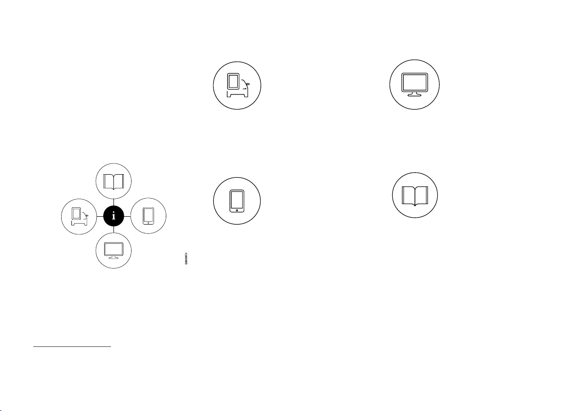
Owner's information is available in several different product formats, both digital and printed.
The owner's manual is available in the car's
screen, as a mobile app and on the Volvo Cars
support site. There is a Quick Guide and a supplement to the owner's manual available in the
glovebox, with specifications and fuse information, amongst other things. A printed owner's
manual can be ordered.
The car's screen
1
A digital version of the owner's
manual is available in the car's
screen. Press the MY CAR button in the centre console, press
OK/MENU and select
Owner's manual. The infor-
mation is searchable and can
also be subdivided into categories.
Read more in the Digital owner's manual in the
car.
Mobile app
In App Store or Google Play,
search for "Volvo Manual",
download the app to your
smartphone or tablet and select
the car.
as well as options for visual navigation with exterior and interior images of the car. It is easy to
navigate between the different sections in the
owner's manual and the content is searchable.
Read more about Owner's Manual in mobile devices.
The app contains video tutorials
Volvo Cars support site
Go to support.volvocars.com
and select your country. Here
you can find owner's manuals,
both online and in PDF format.
On the Volvo Cars support site
there are also video tutorials
and further information and
help regarding your Volvo and your car ownership. The page is available for most markets.
Read more on the Volvo Cars support site.
Printed information
There is a supplement to the
owner's manual2 in the glove-
box that contains information
on fuses and specifications, as
well as a summary of important
and practical information.
There is also a Quick Guide available in printed
format that helps you to get started with the most
commonly used functions in the car.
Depending on equipment level selected, market,
etc. additional owner's information may also be
available in printed format in the car.
A printed owner's manual and associated supplement can be ordered. Contact a Volvo dealer to
order. See how the owner's manual is structured
in Reading the owner's manual.
1
A complete printed manual is included with the car for markets without owner's manual in the screen.
2
A complete printed manual is included with the car for markets without owner's manual in the screen.
12
Page 15
INTRODUCTION
Changing the language in the car's screen
Changing the language in the car's display may
mean that some information does not correspond
to national or local laws and regulations. Don't
change to a language that's difficult to understand, it may then be difficult to find your way
back in the structure on the screen.
IMPORTANT
The driver is always responsible that the vehicle is driven safely in traffic and that applicable laws and regulations are followed. It is
also important that the car is maintained and
handled in accordance with Volvo's recommendations in the owner's information.
If there should be a difference between the
information in the screen and the printed
information then it is always the printed information that applies.
Related information
Digital owner's manual in the car (p. 13)
•
Volvo Cars support site (p. 15)
•
Reading the owner's manual (p. 16)
•
3
Applies to certain car models.
Digital owner's manual in the car
The owner's manual can be read on the screen
in the car3. The content is searchable and it is
easy to navigate between different sections.
Open the digital owner's manual - press the MY
CAR button in the centre console, press OK/
MENU and select
For basic navigation, see Operating the system.
See below for a more detailed description.
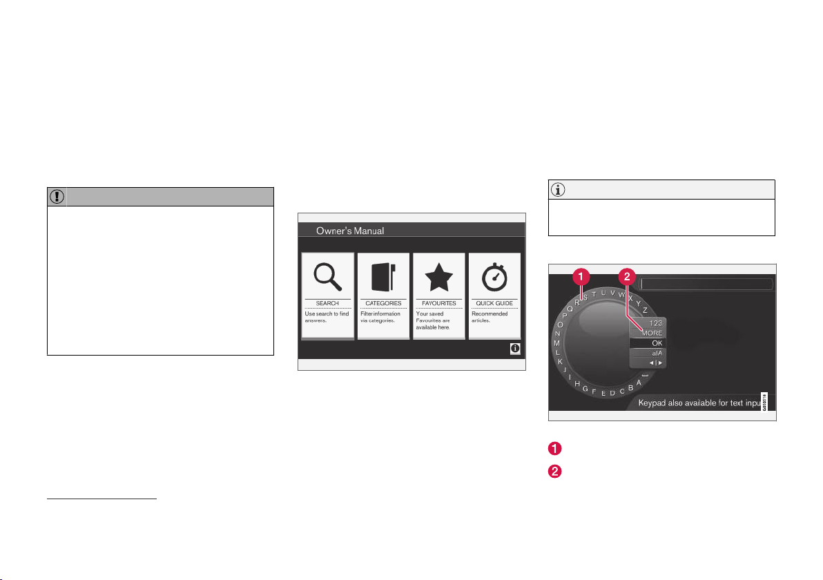
Owner's manual, start page.
There are four options for finding information in
the digital owner's manual:
Search - Search function for finding an arti-
•
cle.
Categories - All articles sorted into catego-
•
ries.
Owner's manual.
Favourites - Quick access to favourite-
•
bookmarked articles.
Quick Guide - A selection of articles for
•
common functions.
Select the information symbol in the lower righthand corner in order to obtain information about
the digital owner's manual.
NOTE
The digital owner's manual is not available
while driving.
Search
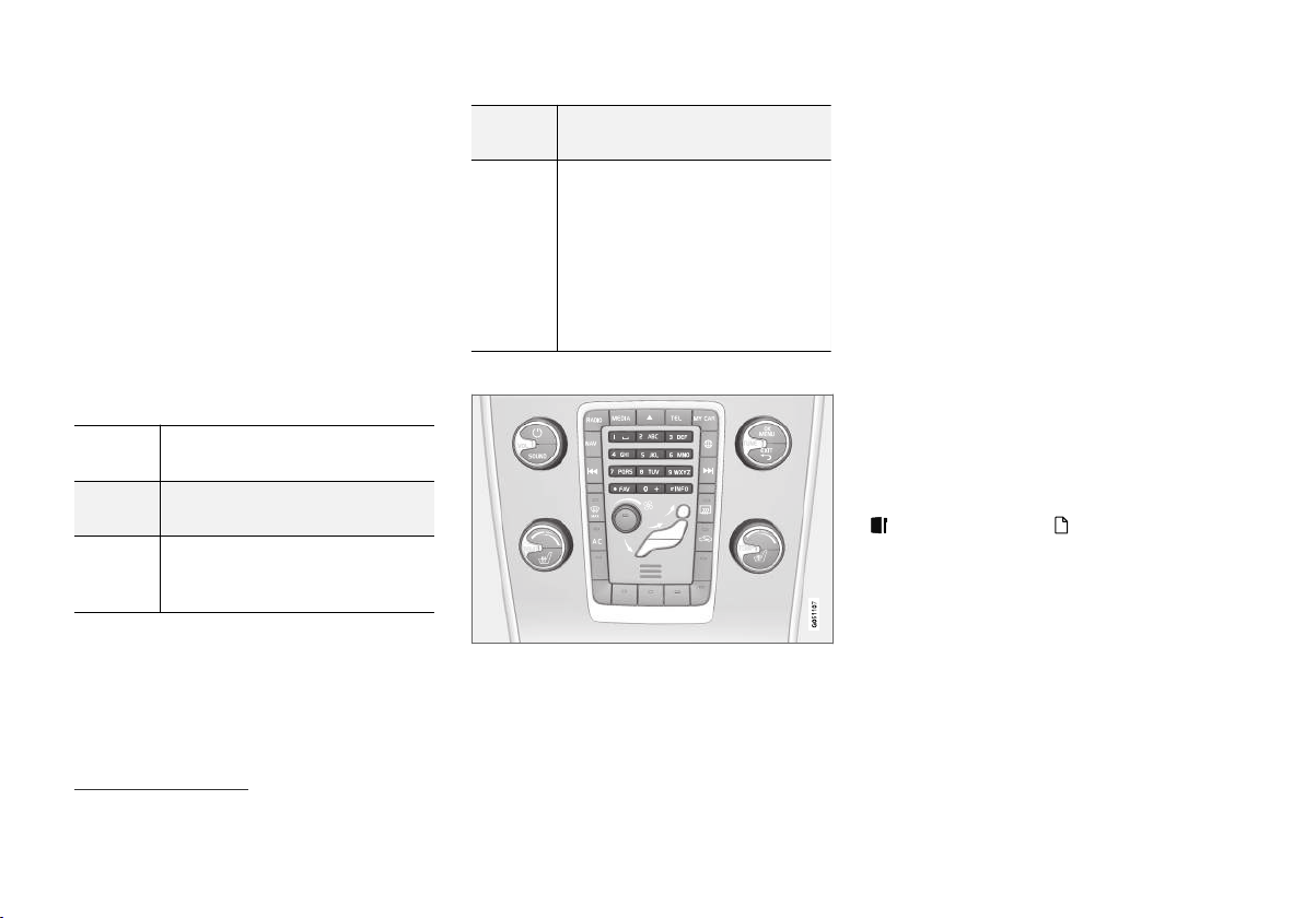
Searching using the character wheel.
Character list.
Changing the input mode (see following
table).
}}
13
Page 16
INTRODUCTION
Use the character wheel to enter a search term,
||
e.g. "seatbelt".
1.
Turn TUNE to the desired letter, press OK/
MENU to confirm. The number and letter
buttons on the control panel in the centre
console can also be used.
2. Continue with the next letter and so on.
3. To change the input mode to numbers or
special characters, or to perform a search,
turn TUNE to one of the options (see explanation in the following table) in the list for
changing the input mode (2), press OK/
MENU.
123/AB
C
MORE
OK
Change between letters and numbers with OK/MENU.
Change to special characters with
OK/MENU.
Perform the search. Turn TUNE to
select a search result article, press
OK/MENU to go to the article.
a|A
| | }
Enter with the numerical keyboard
Numerical keyboard.
Another way of entering characters is to use the
centre console's buttons 0-9, * and #.
Changes between lowercase and
uppercase letters with OK/MENU.
Changes from the character wheel
to the search field. Move the cursor with TUNE. Delete any misspelling with EXIT. To return to the
character wheel, press OK/MENU.
Note that the digit and letter buttons on the control panel can be
used for editing in the search field.
When e.g. 9 is pressed, a bar appears with all
characters4 under the button, e.g.
W, x, y, z and
9. Quick presses on the button move the cursor
through these characters.
Stop with the cursor on the desired character
•
in order to select it - the character is shown
on the enter line.
Delete/undo using EXIT.
•
To enter a number, hold in the corresponding
number key.
Categories
The articles in the owner's manual are structured
into main categories and subcategories. The
same article can be in several appropriate categories in order to be found more easily.
Turn TUNE to navigate in the category tree and
press OK/MENU to open a category - selected
- or article - selected . Press EXIT to go
back to the previous view.
Favourites
Located here are the articles that are saved as
favourites. To select an article as a favourite, see
the heading "Navigating in an article" below.
Turn TUNE to navigate in the favourite list and
press OK/MENU to open an article. Press EXIT
to go back to the previous view.
4
The character for each button may vary depending on market/country/language.
14
Page 17
INTRODUCTION
Quick Guide
Located here is a selection of articles for getting
to know the car's most common functions. The
articles can also be accessed via categories, but
are collected here for quick access.
Turn TUNE to navigate in the Quick Guide and
press OK/MENU to open an article. Press EXIT
to go back to the previous view.
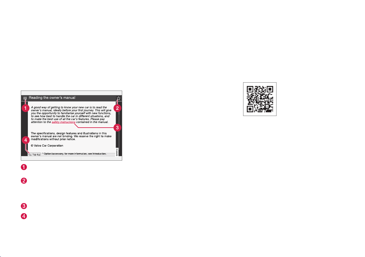
Navigating in an article
Home - leads to the start page for the
owner's manual.
Favourite - adds/removes an article as a
favourite. You can also press the FAV button
in the centre console to add/remove an article as a favourite.
Highlighted link - leads to linked article.
Special texts - if the article contains warn-
ings, important or note texts then an associ-
ated symbol is shown here as well as the
number of such texts in the article.
Turn TUNE to navigate between the links or
scroll in an article. When the screen has scrolled
to the start/end of an article the home and
favourite options are accessed by scrolling a further step up/down. Press OK/MENU to activate
the selection/highlighted link. Press EXIT to go
back to the previous view.
Related information
Volvo Cars support site (p. 15)
•
Volvo Cars support site
More information on your car is available on the
Volvo Cars website and support site.
Support on the Internet
Go to support.volvocars.com or use the QR code
below to visit the page. The support page is available for most markets.
QR code that leads to the support page.
The information on the support page is searchable and can also be subdivided into different categories. Available here is support for options related to e.g. Internet connected services and functions, Volvo On Call*, the navigation system* and
apps. Video and step-by-step instructions explain
different procedures, e.g. how the car is connected to the Internet via a mobile phone.
Downloadable information from the support page
Maps
For cars equipped with Sensus Navigation*, there
is the facility to download maps from the support
page.
}}
* Option/accessory.
15
Page 18
INTRODUCTION
||
Apps
For selected Volvo models from model year 2014
and 2015, the owner's manual is available in the
form of an app. The Volvo On Call* app can also
be accessed from here.
Owner's manuals from previous model years
Owner's manuals from previous model years are
available here in PDF format. The Quick Guide
and supplement can also be accessed from the
support page. Select car model and model year in
order to download the publication required.
Contact
On the support page there is contact information
for customer support and the nearest Volvo
dealer.
Log in to the Volvo Cars website
Create a personal Volvo ID and log in to
www.volvocars.com. Once you are logged in you
can get an overview of service, agreements and
warranties, amongst other things. There is also
information here about accessories and software
adapted for your car model.
Reading the owner's manual
A good way of getting to know your new car is
to read the owner's manual, ideally before your
first journey.
Reading the owner's manual is a good way to
become familiar with new functions, get advice
on how best to handle the car in different situations and learn how to make the best use of all
the car's features. Please pay attention to the
safety instructions contained in the owner's manual.
Development work is constantly in progress to
improve our product. Modifications may mean
that information, descriptions and illustrations in
the owner's manual differ from the equipment in
the car. We reserve the right to make modifications without prior notice.
© Volvo Car Corporation
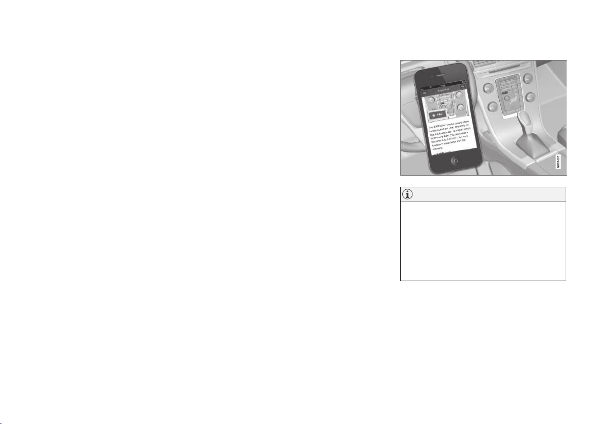
Owner's Manual in mobile devices
NOTE
The Owner's manual is available for download
as a mobile application (applies for certain car
models and mobile devices), see
www.volvocars.com.
The mobile application also includes video
and searchable content and easy navigation
between different sections.
Related information
Volvo ID (p. 20)
•
16
Options/accessories
All types of option/accessory are marked with an
asterisk*.
In addition to standard equipment, the owner's
manual also describes options (factory fitted
equipment) and certain accessories (retrofitted
extra equipment).
* Option/accessory.
Page 19
INTRODUCTION
G031590
G031592
The equipment described in the owner's manual
is not available in all cars - they have different
equipment depending on adaptations for the
needs of different markets and national or local
laws and regulations.
In the event of uncertainty over what is standard
or an option/accessory, contact a Volvo dealer.
Special texts
WARNING
Warning texts appear if there is a risk of
injury.
IMPORTANT
"Important" texts appear if there is a risk of
damage.
NOTE
NOTE texts give advice or tips that facilitate
the use of features and functions for example.
Footnote
There is footnote information in the owner's manual that is located at the bottom of the page. This
information is an addition to the text that it refers
to via a number. If the footnote refers to text in a
table then letters are used instead of numbers
for referral.
Message texts
In the car there are displays that show menu
texts and message texts. In the owner's manual
the appearance of these texts differs from the
normal text. Examples of menu texts and message texts:
Media, Sending location.
Decals
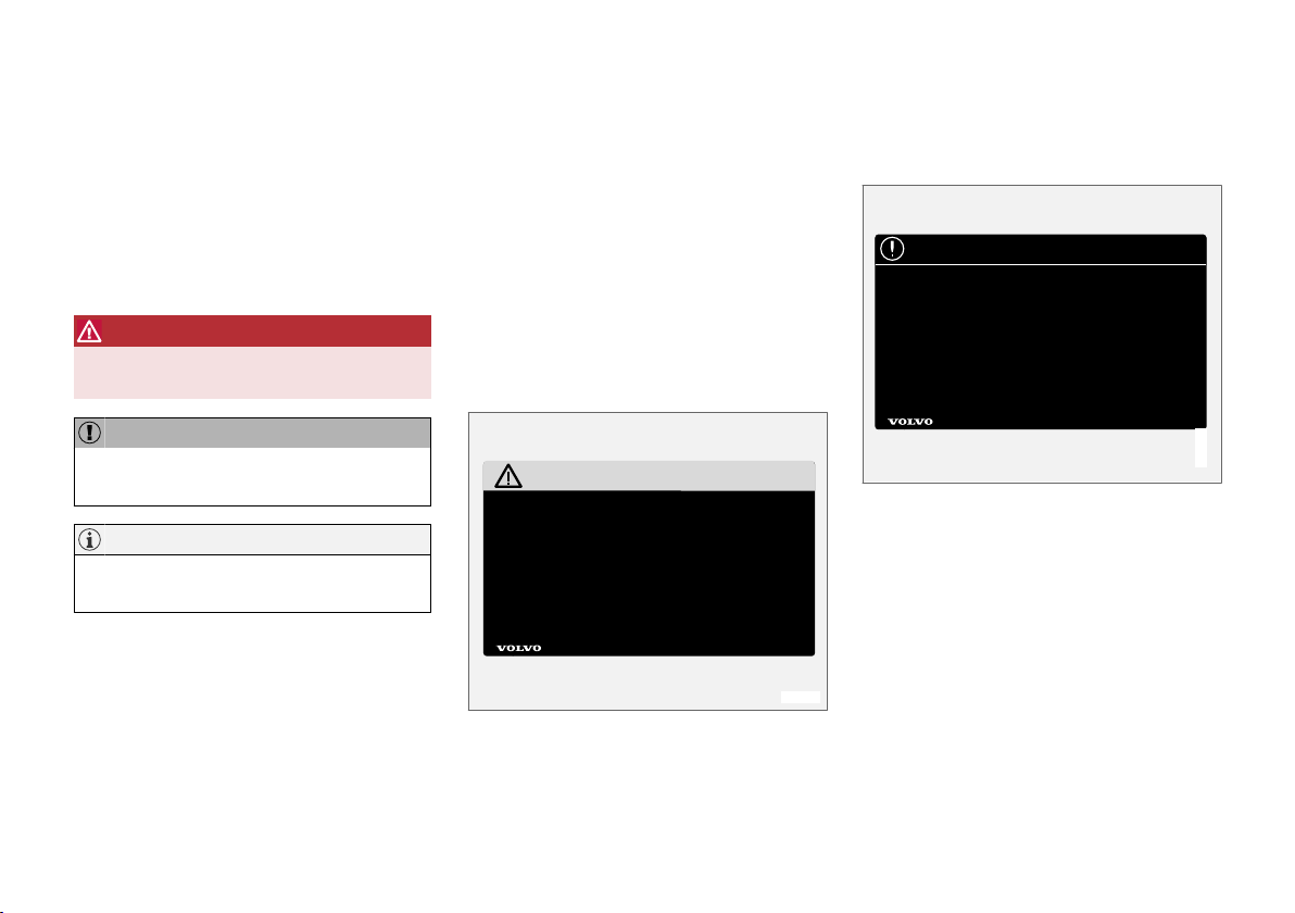
The car contains different types of decal which
are designed to convey important information in a
simple and clear manner. The decals in the car
have the following descending degree of importance for the warning/information.
Warning for personal injury
Black ISO symbols on yellow warning field, white
text/image on black message field. Used to indicate the presence of danger which, if the warning
is ignored, may result in serious personal injury or
fatality.
Risk of property damage
White ISO symbols and white text/image on
black or blue warning field and message field.
Used to indicate the presence of danger which, if
the warning is ignored, may result in damage to
property.
}}
17
Page 20
INTRODUCTION
G031593
||
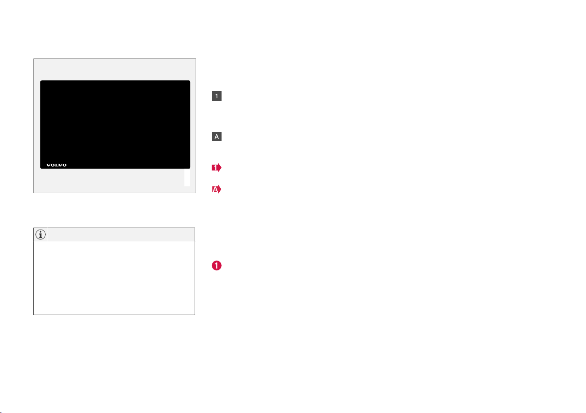
Information
White ISO symbols and white text/image on
black message field.
NOTE
It is not intended that the decals illustrated in
the owner's manual should be exact replicas
of those in the car. They are included to show
their approximate appearance and locations
in the car. The information that applies to your
particular car can be found on the decal on
the car.
Procedure lists
Procedures where action must be taken in a certain sequence are numbered in the owner's manual.
When there is a series of illustrations for
step-by-step instructions each step is numbered in the same way as the corresponding
illustration.
Lists of letters appear adjacent to the series
of illustrations where the order of the instructions is not significant.
Arrows appear numbered and unnumbered
and are used to illustrate a movement.
Arrows with letters are used to clarify a
movement when the reciprocal order is of no
relevance.
If there is no series of illustrations for step-bystep instructions then the different steps are
numbered with normal numbers.
Position lists
Red circles containing a number are used in
overview images where different components
are pointed out. The number recurs in the
position list featured in connection with the
illustration that describes the item.
Bulleted lists
A bulleted list is used when there is a list of
points in the owner's manual.
Example:
Coolant
•
Engine oil
•
Related information
Related information refers to other articles containing closely-associated information.
Images
The manual's images are sometimes schematic
and may deviate from the car's appearance
depending on equipment level and market.
To be continued
}}
This symbol is located furthest down to the
right when an article continues on the following
page.
Continued from previous page
||
This symbol is located furthest up to the left
when an article continues from the previous
page.
Related information
The owner's manual and the environment
•
(p. 25)
Volvo Cars support site (p. 15)
•
18
Page 21

INTRODUCTION
Recording data
As part of Volvo's safety and quality assurance,
certain information about the vehicle's operation,
functionality and incidents are recorded in the
car.
This vehicle is equipped with an "Event Data
Recorder" (EDR). Its primary purpose is to register and record data related to traffic accidents or
collision-like situations, such as times when the
airbag deploys or the vehicle strikes an obstacle
in the road. The data is recorded in order to
increase understanding of how vehicle systems
work in these types of situations. The EDR is
designed to record data related to vehicle
dynamics and safety systems for a short time,
usually 30 seconds or less.
The EDR in this vehicle is designed to record
data related to the following in the event of traffic
accidents or collision-like situations:
How the various systems in the car worked
•
Whether the driver and passenger seatbelts
•
were fastened/tensioned
The driver's use of the accelerator or brake
•
pedal
The travel speed of the vehicle
•
This information can help us better understand
the circumstances in which traffic accidents, injuries and damage occur. The EDR only records
data when a non-trivial collision situation occurs.
The EDR does not record any data during normal
driving conditions. Similarly, the system never
registers who is driving the vehicle or the geographic location of the accident or near-miss situation. However, other parties, such as the police,
could use the recorded data in combination with
the type of personally identifiable information
routinely collected after a traffic accident. Special
equipment and access to either the vehicle or the
EDR is required to be able to interpret the registered data.
In addition to the EDR, the car is equipped with a
number of computers designed to continually
check and monitor the function of the car. They
can record data during normal driving conditions,
but in particular register faults affecting the vehicle's operation and functionality, or upon activation of the vehicle's active driver support function
(e.g. City Safety and the auto brake function).
Some of the recorded data is required to enable
service and maintenance technicians to diagnose
and remedy any faults that occurred in the vehicle. The registered information is also needed to
enable Volvo to satisfy legal requirements laid out
in laws and by government authorities. Information registered in the vehicle is stored in its computer until the vehicle is serviced or repaired.
In addition to the above, the registered information can be used in aggregate form for research
and product development with the aim of continuously improving the safety and quality of Volvo
cars.
Volvo will not contribute to the above-described
information being disclosed to third parties without the vehicle owner's consent. To comply with
national legislation and regulations, Volvo may be
forced to disclose information of this nature to
the police or other authorities who may assert a
legal right to access such. Special technical
equipment which Volvo and workshops that have
entered into agreements with Volvo have access
to is required to be able to read and interpret the
recorded data. Volvo is responsible that the information, which is transferred to Volvo during servicing and maintenance, is stored and handled in a
secure manner and that the handling complies
with applicable legal requirements. For further
information - contact a Volvo dealer.
19
Page 22
INTRODUCTION
Accessories and extra equipment
The incorrect connection and installation of
accessories and extra equipment can negatively
affect the car's electronic system.
Certain accessories only function when associated software is installed in the car's computer
system. Volvo therefore recommends that you
always contact an authorised Volvo workshop
before installing accessories or extra equipment
which are connected to or affect the electrical
system.
Heat-reflecting windscreen*
The windscreen is equipped with a heat-reflecting film (IR) that reduces the solar heat radiation
into the passenger compartment.
If a road toll tag or similar device is used to pass
through road tolls then it is important that it is
positioned so that it is not covered by the heatreflective film. If electronic equipment us positioned behind a glass surface with heat-reflective
film then it can have a negative effect on its function and performance.
Remember that the road toll tag must not cover
or interfere with sensors or cameras fitted in or
adjacent to the windscreen.
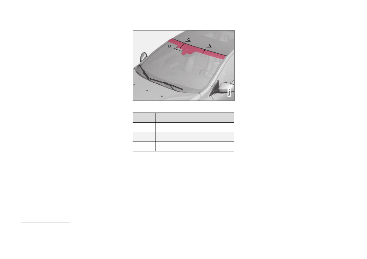
Areas where IR film is not applied.
Dimensions
A 65 mm
B 150 mm
C 125 mm
Volvo ID
Volvo ID provides access to a wide range of personalized Volvo services5 online.
Examples of services:
In an Internet-connected car* - Certain func-
•
tions and services require that you have registered your car to a personal Volvo ID, for
example to be able to send a new address
from a map service on the Internet directly to
the car.
Volvo On Call* - Volvo ID is used when log-
•
ging in to the Volvo On Call app.
Advantages of Volvo ID
One user name and one password to access
•
online services, i.e. only one username and
one password to remember.
When changing the username/password for
•
a service (e.g. Volvo On Call) it will also be
changed automatically for other services.
Create a Volvo ID
To create a Volvo ID you need to enter a personal
e-mail address. Then follow the instructions in
the e-mail message that is automatically sent to
the specified address in order to complete the
registration. It is possible to create a Volvo ID via
one of the following services:
5
The services available may vary over time and vary depending on equipment level and market.
20
* Option/accessory.
Page 23

Volvo Cars website - Go to
•
www.volvocars.com and log in6 at the icon,
top right. Select Create Volvo ID.
For an Internet-connected car* - Enter your
•
e-mail address in the app that requires Volvo
ID and follow the instructions. Alternatively,
press the Connect button
console twice and select
and follow the instructions.
Volvo On Call* - Download the latest version
•
of the Volvo On Call app. Choose to create a
Volvo ID from the start page, enter e-mail
address and follow the instructions.
in the centre
Apps Settings
Related information
Volvo Cars support site (p. 15)
•
INTRODUCTION
6
Available in certain markets.
* Option/accessory.
21
Page 24
INTRODUCTION
Environmental philosophy
Volvo Car Corporation is constantly working on
the development of safer and more efficient
Environmental care is one of Volvo Cars’ core values and influences all operations. The environmental work is based on the whole life cycle of
the car and takes into account the environmental
impact it has, from design to scrapping and recycling. Volvo Cars' basic principle is that every new
product developed must have less impact on the
environment than the product it replaces.
Volvo's environmental management work has
resulted in the development of the more efficient
and less polluting Drive-E drivelines. The personal
environment is also important to Volvo - the air
products and solutions in order to reduce the
negative impact on the environment.
inside a Volvo is, for example, cleaner than the air
outside thanks to the climate control system.
Your Volvo complies with stringent international
environmental standards. All Volvo's manufacturing units must be ISO 14001 certified, and this
supports a systematic approach to the operation's environmental issues, which leads to continuous improvement with reduced environmental
impact. Holding the ISO certificate also means
that environmental laws and regulations in force
are complied with. Volvo also requires that its
partners must also meet these requirements.
Fuel consumption
Since a large part of a car's total environmental
impact stems from its use, the emphasis of Volvo
Cars' environmental work is on reducing fuel consumption, carbon dioxide emissions and other air
pollutants. Volvo cars have competitive fuel consumption in each of their respective classes.
Lower fuel consumption generally results in lower
emission of the greenhouse gas, carbon dioxide.
22
Page 25

INTRODUCTION
Contributing to a better environment
An energy-efficient and fuel-efficient car not only
contributes to a reduced impact on the environment, but also means reduced costs for the
owner of the car. As the driver, it is easy to
reduce fuel consumption and thereby save
money and contribute to a better environment here is some advice:
Plan for an effective average speed. Speeds
•
above approx. 80 km/h (50 mph) and below
50 km/h (30 mph) lead to increased energy
consumption.
Follow the Service and Warranty Booklet's
•
recommended intervals for service and maintenance of the car.
Avoid letting the engine idle - switch off the
•
engine when stationary for longer periods.
Pay attention to local regulations.
Plan the journey - a lot of unnecessary stops
•
and uneven speed contribute to increased
fuel consumption.
If the car is equipped with an engine block
•
heater*, use it before starting from cold - it
improves starting capacity and reduces wear
in cold weather and the engine reaches normal operating temperature more quickly,
which lowers consumption and reduces
emissions.
Also remember to always dispose of environmentally hazardous waste, such as batteries and oil, in
an environmentally safe manner. Consult a work-
shop in the event of uncertainty about how this
type of waste should be discarded - an authorised Volvo workshop is recommended.
Following this advice can save money, the planet's resources are saved, and the car's durability
is extended. For more information and further
advice, see Eco guide (p. 70), Economical driving (p. 302) and Fuel consumption (p. 398).
Efficient emission control
Your Volvo is manufactured following the concept
"Clean inside and out" – a concept that encompasses a clean interior environment as well as
highly efficient emission control. In many cases
the exhaust emissions are well below the applicable standards.
Clean air in the passenger compartment
A passenger compartment filter prevents dust
and pollen from entering the passenger compartment via the air intake.
The Interior Air Quality System (IAQS)* ensures
that the incoming air is cleaner than the air in the
traffic outside.
The system cleans the air in the passenger compartment from contaminants such as particles,
hydrocarbons, nitrous oxides and ground-level
ozone. If the outside air is contaminated then the
air intake is closed and the air is recirculated.
Such a situation may arise in heavy traffic,
queues and tunnels for example.
IAQS is a part of the Clean Zone Interior Package (CZIP)*, which also includes a function that
allows the fan to start when the car is unlocked
with the remote control key.
Interior
The material used in the interior of a Volvo is
carefully selected and has been tested in order to
be pleasant and comfortable. Some of the details
are hand-made, such as the seams of the steering wheel that are sewn by hand. The interior is
monitored in order not to emit strong odours or
substances that cause discomfort in the event of
e.g. high heat and bright light.
Volvo workshops and the environment
Regular maintenance creates the conditions for a
long service life and low fuel consumption for
your car. In this way you also contribute to a
cleaner environment. When Volvo's workshops
are entrusted with the service and maintenance
of your car it becomes part of Volvo's system.
Volvo makes clear demands regarding the way in
which workshop premises shall be designed in
order to prevent spills and discharges into the
environment. The workshop staff have the knowledge and the tools required to guarantee good
environmental care.
Recycling
Since Volvo works from a life cycle perspective, it
is also important that the car is recycled in an
environmentally sound manner. Almost all of the
car can be recycled. The last owner of the car is
}}
* Option/accessory.
23
Page 26

INTRODUCTION
therefore requested to contact a dealer for refer-
||
ral to a certified/approved recycling facility.
Related information
The owner's manual and the environment
•
(p. 25)
24
Page 27
INTRODUCTION
The owner's manual and the environment
The paper pulp in a printed owner's manual
comes from Forest Stewardship Council® certified forests or other controlled sources.
The FSC® symbol shows that the paper pulp in a
printed owner's manual comes from FSC® certified forests or other controlled sources.
Related information
Environmental philosophy (p. 22)
•
Laminated glass
The glass is reinforced which provides
better protection against break-ins and
improved sound insulation in the passenger compartment. The windscreen
and other windows* have laminated glass.
* Option/accessory.
25
Page 28

Page 29

SAFETY
Page 30
SAFETY
General information on seatbelts
Heavy braking can have serious consequences
if the seatbelts are not used. Ensure that all passengers are using their seatbelts during the journey.
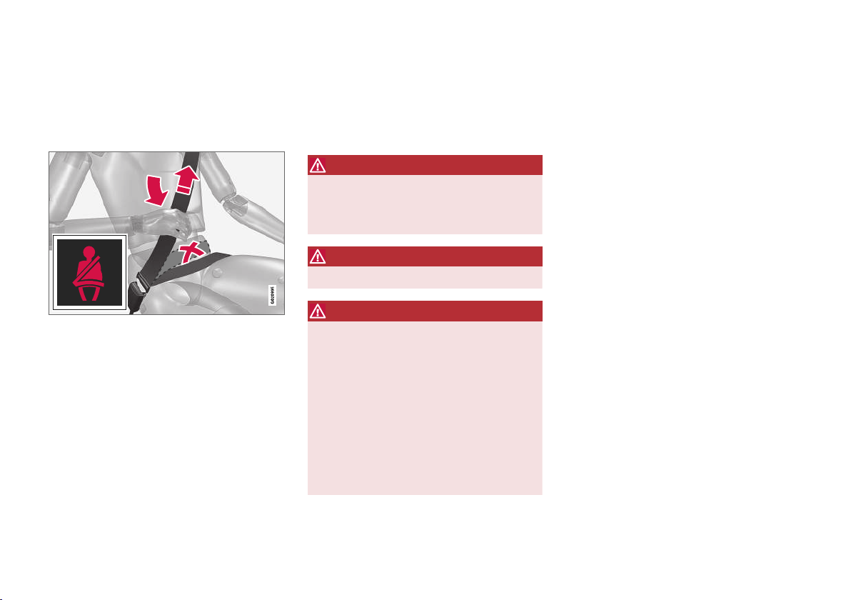
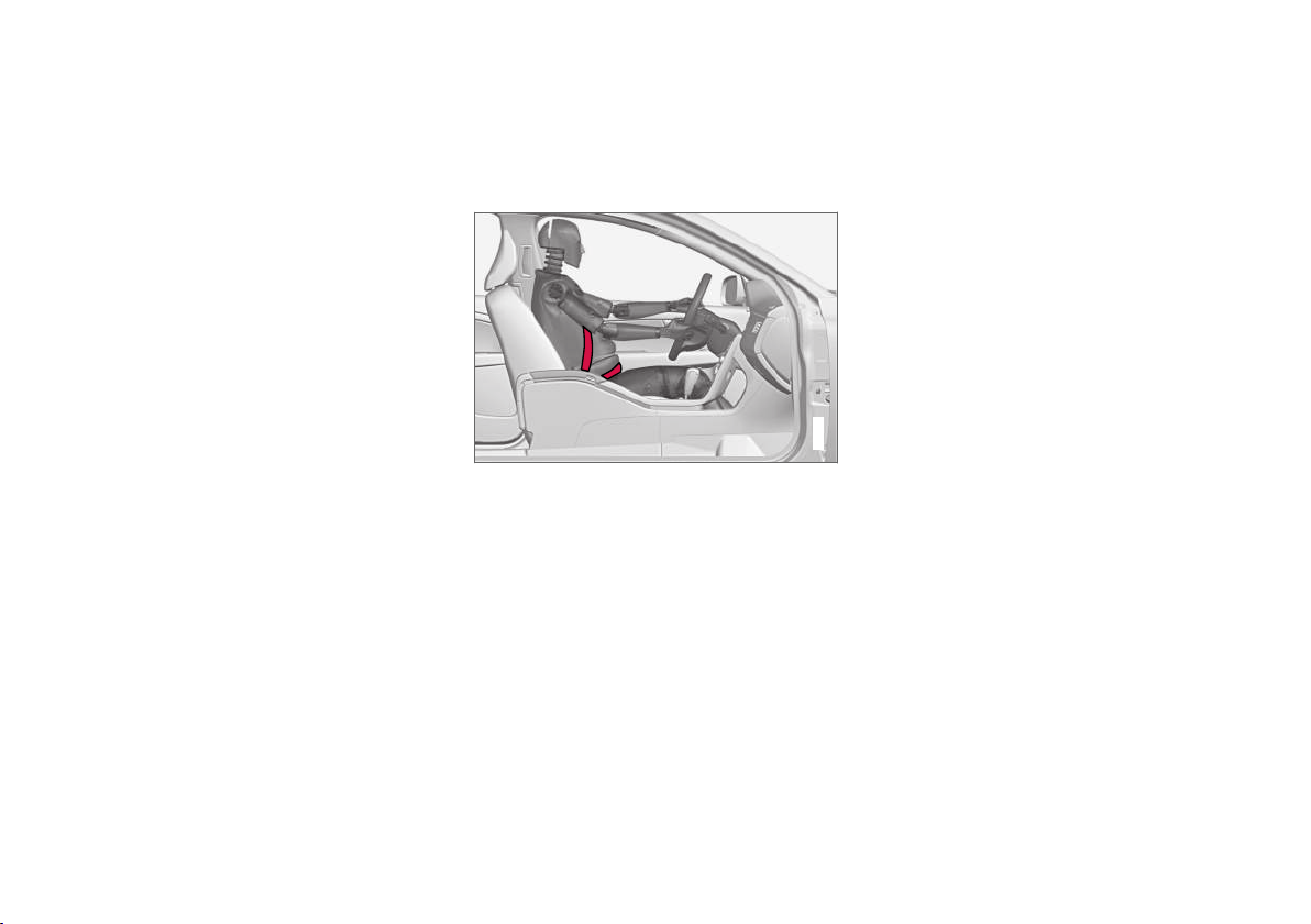
Tension the hip strap over the lap by pulling the diagonal
shoulder belt up towards the shoulder. The hip strap
must be positioned low down (not over the abdomen).
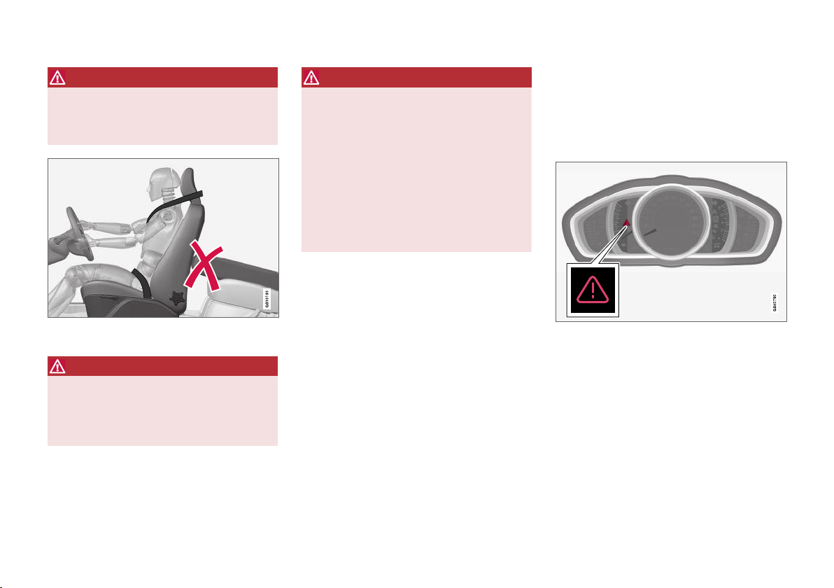
It is important that the seatbelt lies against the
body so it can provide maximum protection. Do
not lean the backrest too far back. The seatbelt is
designed to protect in a normal seating position.
Unbelted occupants will be reminded to fasten
their (p. 29) seatbelt by means of an audio and
visual reminder (p. 31).
Remember
Do not use clips or anything else that can
•
prevent the seatbelt from fitting properly.
The seatbelt must not be twisted or caught
•
on anything.
WARNING
The seatbelts and airbags interact. If a seatbelt is not used or is used incorrectly, this may
diminish the protection provided by the airbag
in the event of a collision.
WARNING
Each seatbelt is designed for only one person.
WARNING
Never modify or repair the seatbelts yourself.
Volvo recommends that you contact an
authorised Volvo workshop.
If the seatbelt has been subjected to a major
load, such as in conjunction with a collision,
the entire seatbelt must be replaced. Some of
the seatbelt's protective properties may have
been lost even if the seatbelt does not appear
damaged. The seatbelt must also be replaced
if it shows signs of wear or damage. The new
seatbelt must be type-approved and designed
for installation at the same location as the
replaced seatbelt.
Related information
Seatbelt - pregnancy (p. 30)
•
Seatbelt - loosening (p. 30)
•
Seatbelt tensioner (p. 31)
•
28
Page 31
SAFETY
Seatbelt - putting on
Put on the seatbelt (p. 28) before driving starts.
Pull the belt out slowly and secure it by pressing
its locking tab into the seatbelt buckle. A loud
"click" indicates that the belt has locked.
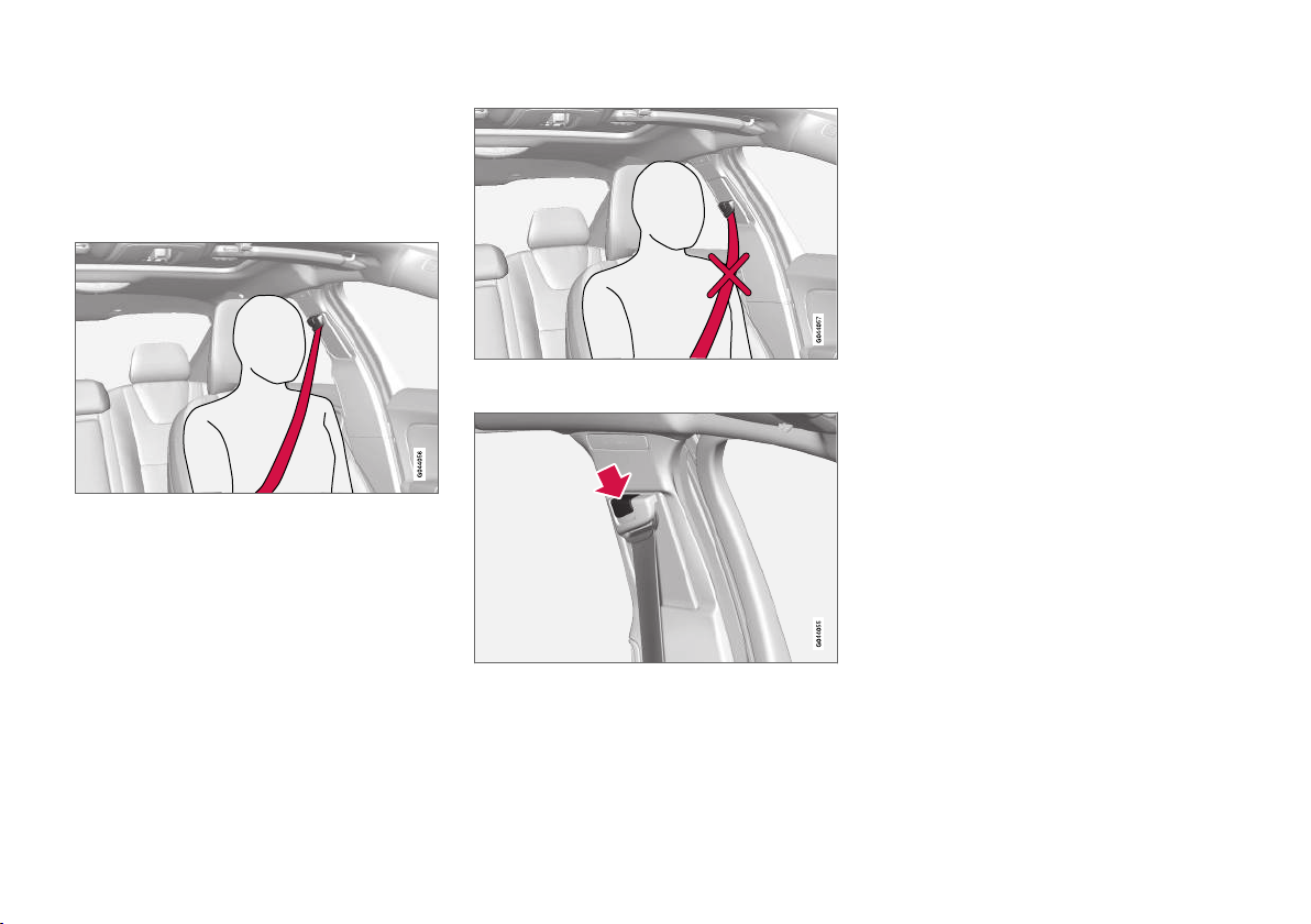
Correctly fitted seatbelt.
Incorrectly fitted seatbelt. The belt must rest on the
shoulder.
Seatbelt height adjustment. Press the button and move
the belt vertically. Position the belt as high as possible
without it chafing against your throat.
The locking tab at the centre rear seat only fits
into the intended seatbelt buckle.
Remember
The seatbelt locks and cannot be withdrawn:
if it is pulled out too quickly
•
during braking and acceleration
•
if the car leans heavily.
•
Related information
Seatbelt - pregnancy (p. 30)
•
Seatbelt - loosening (p. 30)
•
Seatbelt tensioner (p. 31)
•
Seatbelt reminder (p. 31)
•
29
Page 32
SAFETY
G020998
Seatbelt - loosening
Loosen the seatbelt (p. 28) when the car is stationary.
Press the red button on the seatbelt buckle and
then let the belt retract. If the seatbelt does not
retract fully, feed it in by hand so that it does not
hang loose.
Related information
Seatbelt - putting on (p. 29)
•
Seatbelt reminder (p. 31)
•
Seatbelt - pregnancy
Seatbelt (p. 28) must always be worn during
pregnancy. But it is crucial that it be worn in the
correct way.
The diagonal section should wrap over the shoulder then be routed between the breasts and to
the side of the abdomen.
The lap section should lay flat over the thighs and
as low as possible under the abdomen. – It must
never be allowed to ride upward. Remove the
slack from the seatbelt and ensure that it fits as
close to the body as possible. In addition, check
that there are no twists in the seatbelt.
As the pregnancy progresses, pregnant drivers
must adjust the seat (p. 82) and steering wheel
(p. 87) such that they can easily maintain control of the vehicle as they drive (which means that
they must be able to easily operate the foot pedals and steering wheel). The aim should be to
position the seat with as large a distance as possible between abdomen and steering wheel.
Related information
Seatbelt - putting on (p. 29)
•
Seatbelt - loosening (p. 30)
•
30
Page 33
SAFETY
Seatbelt reminder
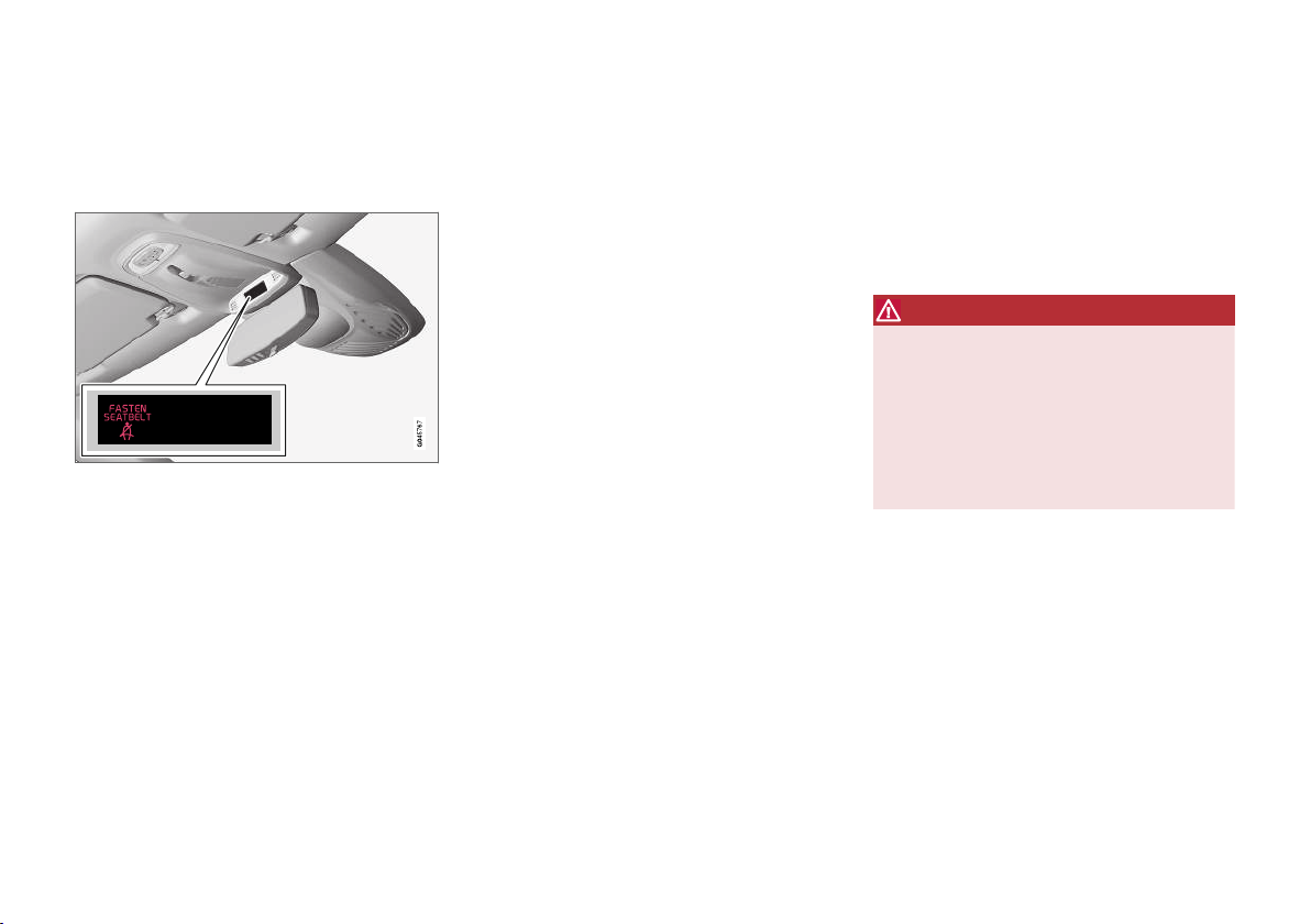
Unbelted occupants will be reminded to fasten
their (p. 29) seatbelt by means of an audio and
visual reminder.
The audio reminder is speed dependent, and in
some cases time dependent. The visual reminder
is located in the roof console and in the combined instrument panel (p. 66).
Child seats are not covered by the seatbelt
reminder system.
Rear seat
The seatbelt reminder in the rear seat has two
subfunctions:
Provides information on which seatbelts
•
(p. 28) are being used in the rear seat. A
message appears in the combined instrument panel when the seatbelts are in use, or
if one of the rear doors has been opened.
The message is acknowledged automatically
after approximately 30 seconds driving or
after pressing the indicator stalk OK button
(p. 110). If anyone is unbelted then the message can only be acknowledged manually by
pressing the indicator stalk OK button.
Provides a warning if one of the rear seat-
•
belts is unfastened during travel. This warning takes the form of a message in the combined instrument panel along with the audio/
visual signal. The warning stops when the
seatbelt is re-fastened, or it can also be
acknowledged manually by pressing the OK
button.
The combined instrument panel's information display shows which seatbelts are in use. This information is always available.
Seatbelt tensioner
Seatbelts (p. 28) on the driver's side, the passenger side and at the outer rear seats are fitted
with seatbelt tensioners. A mechanism in the
seatbelt tensioner tightens the seatbelt in the
event of a sufficiently violent collision. The seatbelt then provides more effective restraint for the
occupants.
WARNING
Never insert the tongue of the passenger's
seatbelt into the buckle on the driver's side.
Always insert the tongue of the seatbelt into
the buckle on the correct side. Do not make
any damages on seatbelts nor insert any foreign objects into a buckle. The seatbelts and
buckles would then possibly not function as
intended in the event of a collision. There is a
risk of serous injury.
Related information
General information on seatbelts (p. 28)
•
31
Page 34
SAFETY
Safety - warning symbol
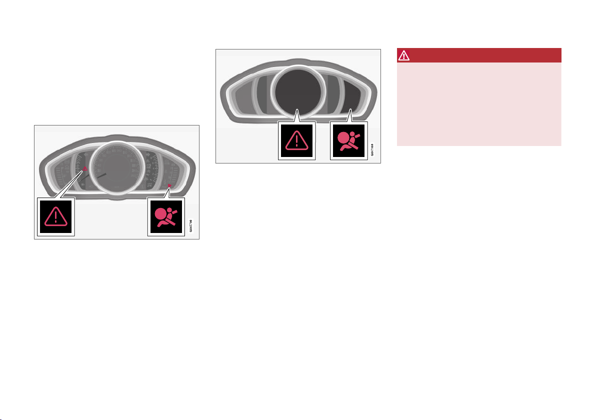
The warning symbol is shown if a fault is
detected during fault tracing or if a system has
been activated. Where required, the warning
symbol is shown together with a message in the
combined instrument panel (p. 66) information
display.
Warning triangle and warning symbol for the airbag system (p. 33) in the analogue combined instrument
panel.
Warning triangle and warning symbol for the airbag system in the digital combined instrument panel.
The warning symbol in the combined instrument
panel is switched on with the remote control key
in key position II (p. 81), fault tracing is performed each time the ignition is switched on. The
symbol clears after approx. 6 seconds provided
the airbag system is fault-free.
The warning symbol is shown if a fault is
detected during fault tracing or if a system has
been activated. Where required, the warning symbol is shown together with a message in the display. If the warning symbol malfunctions, the
warning triangle illuminates and
SRS airbag
Service required or SRS airbag Service
appears in the display. Volvo recom-
urgent
mends that you contact an authorised Volvo
workshop immediately.
WARNING
If the warning symbol for the airbag system
remains illuminated or illuminates while driving, it means that the airbag system does not
have full functionality. The symbol indicates a
fault in the airbag system, the belt tensioner
system, SIPS, the IC system or some other
fault in the system. Volvo recommends that
you contact an authorised Volvo workshop
immediately.
Related information
General information on safety mode (p. 41)
•
32
Page 35
SAFETY
G018665
G018666
Airbag system
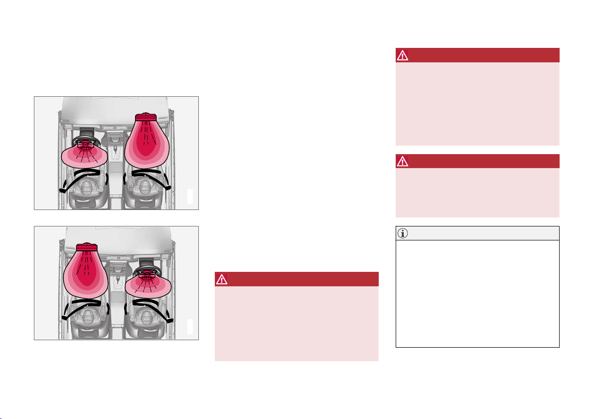
In the event of a frontal collision the airbag system helps to protect the head, face and chest of
the driver and passenger.
Airbag system viewed from above, left-hand-drive car.
Airbag system viewed from above, right-hand-drive car.
The system consists of airbags and sensors. A
sufficiently violent collision trips the sensors and
the airbag(s) are inflated and become hot. The
airbag cushions the initial collision impact for the
occupant. The airbag deflates when compressed
by the collision. When this occurs, smoke
escapes into the car. This is completely normal.
The entire process, including inflation and deflation of the airbag, occurs within tenths of a second.
If the airbags have deployed, the following is recommended:
Recovering the car. Volvo recommends that
•
you have it conveyed to an authorised Volvo
workshop. Do not drive with deployed airbags.
Volvo recommends that you engage an
•
authorised Volvo workshop to handle the
replacement of components in the car's
safety systems.
Always contact a doctor.
•
WARNING
The airbag system's control module is located
in the centre console. If the centre console is
drenched with water or other liquid, disconnect the battery cables. Do not attempt to
start the car since the airbags may deploy.
Recovering the car. Volvo recommends that
you have it conveyed to an authorised Volvo
workshop.
WARNING
Never drive with deployed airbags. They can
make steering difficult. Other safety systems
may also be damaged. The smoke and dust
created when the airbags are deployed can
cause skin and eye irritation/injury after intensive exposure. In case of irritation, wash with
cold water. The rapid deployment sequence
and airbag fabric may cause friction and skin
burns.
WARNING
Volvo recommends that you contact an
authorised Volvo workshop for repair. Defective work in the airbag system could cause
malfunction and result in serious personal
injury.
NOTE
The detectors react differently depending on
the nature of the collision and whether or not
the seatbelt is fastened. Applies to all seatbelt positions apart from centre seat rear.
It is therefore possible that only one (or none)
of the airbags may inflate in a collision. The
detectors sense the force of the collision on
the vehicle and the action is adapted accordingly so that one or more airbags are
deployed.
}}
33
Page 36
SAFETY
||
Related information
Airbags on driver's side (p. 34)
•
Passenger airbag (p. 35)
•
Safety - warning symbol (p. 32)
•
Airbags on driver's side
To supplement the protection afforded by the
seatbelt (p. 28) on the driver side, the car is
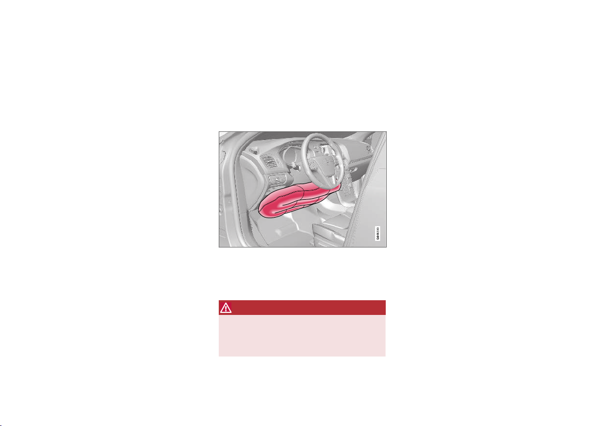
equipped with two airbags (p. 33).
One of the airbags is folded up into the centre of
the steering wheel. The steering wheel is marked
AIRBAG.
Knee airbag on the driver's side in a left-hand-drive car.
The second airbag (at knee level) is fitted in the
lower part of the instrument panel on the driver's
side; this panel is labelled AIRBAG.
WARNING
The seatbelts and airbags interact. If the belt
is not used or is used incorrectly, this may
diminish the protection provided by the airbags in the event of a collision.
Related information
Passenger airbag (p. 35)
•
34
Page 37
SAFETY
Passenger airbag
To supplement the protection afforded by the
seatbelt (p. 28) on the passenger side, the car
is equipped with an airbag (p. 33).
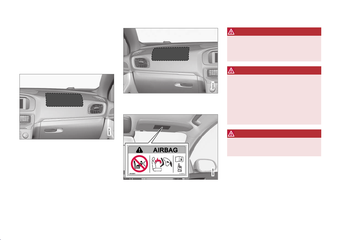
The airbag is folded up into a compartment
above the glovebox. Its cover panel is marked
AIRBAG.
Location of the front passenger airbag in a left-hand
drive car.
Location of the front passenger airbag in a right-hand
drive car.
Label for passenger airbag
Label on the passenger side's sun visor.
The warning label for the passenger airbag is
positioned as shown above.
WARNING
Never use a rear-facing child seat on a seat
protected by an activated airbag. Failure to
follow this advice can lead to death or serious
injury to the child.
WARNING
The seatbelts and airbags interact. If the belt
is not used or is used incorrectly, this may
diminish the protection provided by the airbag
in the event of a collision.
To minimise the risk of injury if the airbag
deploys, passengers must sit as upright as
possible with their feet on the floor and backs
against the backrest. Seatbelts must be
secured.
WARNING
Do not put objects in front of or above the
dashboard where the passenger airbag is
located.
}}
35
Page 38
SAFETY
||
WARNING
Never allow anybody to stand or sit in front of
the front passenger seat.
Never use a rear-facing child seat on the front
passenger seat if the passenger airbag is
activated.
Front-facing passengers (children and adults)
must never sit on the front passenger seat if
the passenger airbag is deactivated.
Failure to follow the advice given above can
endanger life or lead to serious personal
injury.
Switch - PACOS*
The front passenger airbag can be deactivated
(p. 36) if the car is equipped with a switch,
PACOS (Passenger Airbag Cut Off Switch).
WARNING
If the car is equipped with an airbag for the
front passenger seat, but does not have a
switch PACOS (Passenger Airbag Cut Off
Switch), then the airbag will always be activated.
Related information
Airbags on driver's side (p. 34)
•
Child seats (p. 47)
•
Passenger airbag - activating/ deactivating*
The front passenger airbag (p. 35) can be deactivated if the car is equipped with a switch,
PACOS (Passenger Airbag Cut Off Switch).
Switch - PACOS
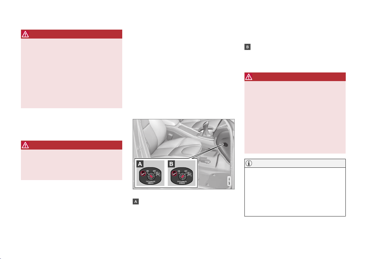
The switch for the passenger airbag (PACOS) is
located on the passenger end of the instrument
panel and is accessible when the passenger door
is open.
Check that the switch is in the required position.
The remote control key's key blade (p. 163)
should be used to change position.
Location of airbag switch.
ON- the airbag is activated. With the switch
in this position, all front-facing passengers
(children and adults) can sit safely on the
passenger seat.
OFF - the airbag is deactivated. With the
switch in this position, children in rear-facing
child seats can sit safely on the front passenger seat.
WARNING
Activated airbag (passenger seat):
Never use a rear-facing child seat on the front
passenger seat when the passenger airbag is
activated.
Deactivated airbag (passenger seat):
Front-facing passengers (children and adults)
must never sit on the front passenger seat
when the passenger airbag is deactivated.
Failure to follow the advice given above can
endanger life or lead to serious personal
injury.
NOTE
When the remote control key is in key position II (p. 81) the warning symbol (p. 32) for
the airbag is shown in the combined instrument panel for approx. 6 seconds.
Following which, the indicator in the roof console is illuminated showing the correct status
for the front passenger seat airbag.
36
* Option/accessory.
Page 39
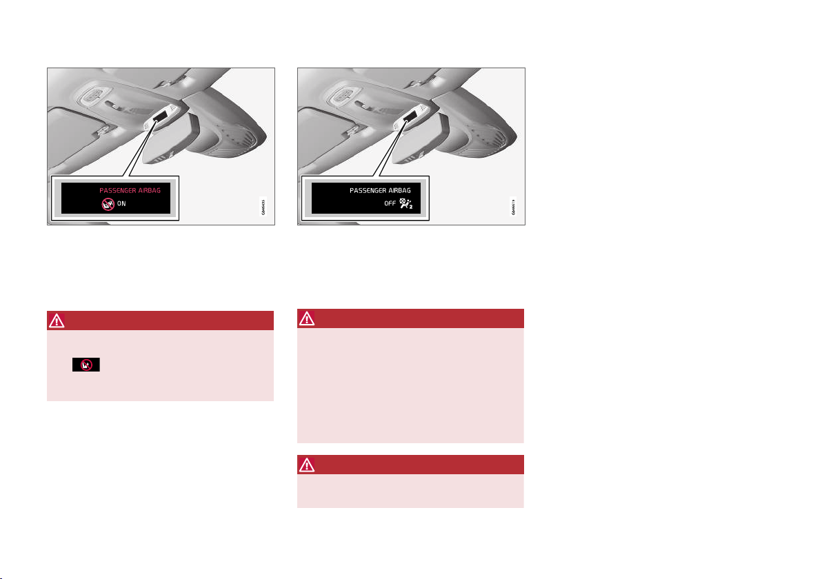
Related information
Child seats (p. 47)
•
SAFETY
Indicator showing that the passenger airbag is activated.
A text message and a warning symbol in the roof
console indicate that the airbag for the front passenger seat is activated (see preceding illustration).
WARNING
Never use a rear-facing child seat on the front
seat if the passenger airbag is activated and
the
nated to indicate this. Failure to follow this
advice could endanger the life of the child.
symbol in the roof console is illumi-
Indicator showing that the passenger airbag is deactivated.
A text message and a symbol in the roof console
indicate that the airbag for the front passenger
seat is deactivated (see preceding illustration).
WARNING
Do not allow anyone to sit in the front passenger seat if the message in the roof console indicates that the airbag is deactivated,
and if the warning symbol (p. 32) for the airbag system is also displayed on the combined
instrument panel. This indicates that there has
been a severe malfunction. Visit a workshop
as soon as possible. Volvo recommends that
you contact an authorised Volvo workshop.
WARNING
Failure to follow the advice given above can
endanger the lives of passengers in the car.
37
Page 40
SAFETY
Side airbag (SIPS)
In a side impact collision a large proportion of
the collision force is transferred by the SIPS
(Side Impact Protection System) to beams, pillars, the floor, the roof and other structural parts
of the body. The side airbags at the driver's and
front passenger seats protect the chest area and
the hip and are an important part of the SIPS.
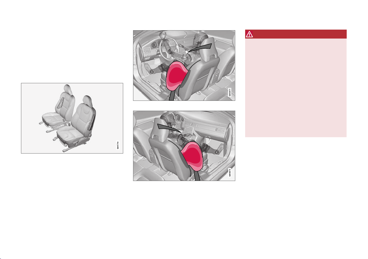
The SIPS bag system consists of two main components, side airbag and sensors. The side airbags are located in the front seat's backrests.
A sufficiently violent collision trips the sensors
and the side airbags are inflated. The airbag
inflates between the occupant and the door
panel and thereby cushions the initial impact. The
airbag deflates when compressed by the collision.
The side airbag is normally only deployed on the
side of the collision.
Driver's seat, left-hand drive.
Front passenger seat, left-hand drive.
WARNING
Volvo recommends that repairs are only
•
carried out by an authorised Volvo workshop. Defective work in the SIPS-bag
system could cause malfunction and
result in serious personal injury.
Do not put objects in the area between
•
the outside of the seat and the door
panel, since this area is required by the
side airbag.
Volvo recommends the use only of car
•
seat covers approved by Volvo. Other seat
covers may impede the operation of the
side airbags.
Side airbags are a supplement the seat-
•
belts. Always use a seatbelt.
SIPS and child seats
The protection provided by the car to children
seated in a child seat or on a booster cushion is
not diminished by the side airbag.
Related information
Airbags on driver's side (p. 34)
•
Passenger airbag (p. 35)
•
Inflatable Curtain (IC) (p. 39)
•
38
Page 41
SAFETY
Inflatable Curtain (IC)
The inflatable curtain helps to prevent the driver
and passengers from striking their heads on the
inside of the car during a collision.
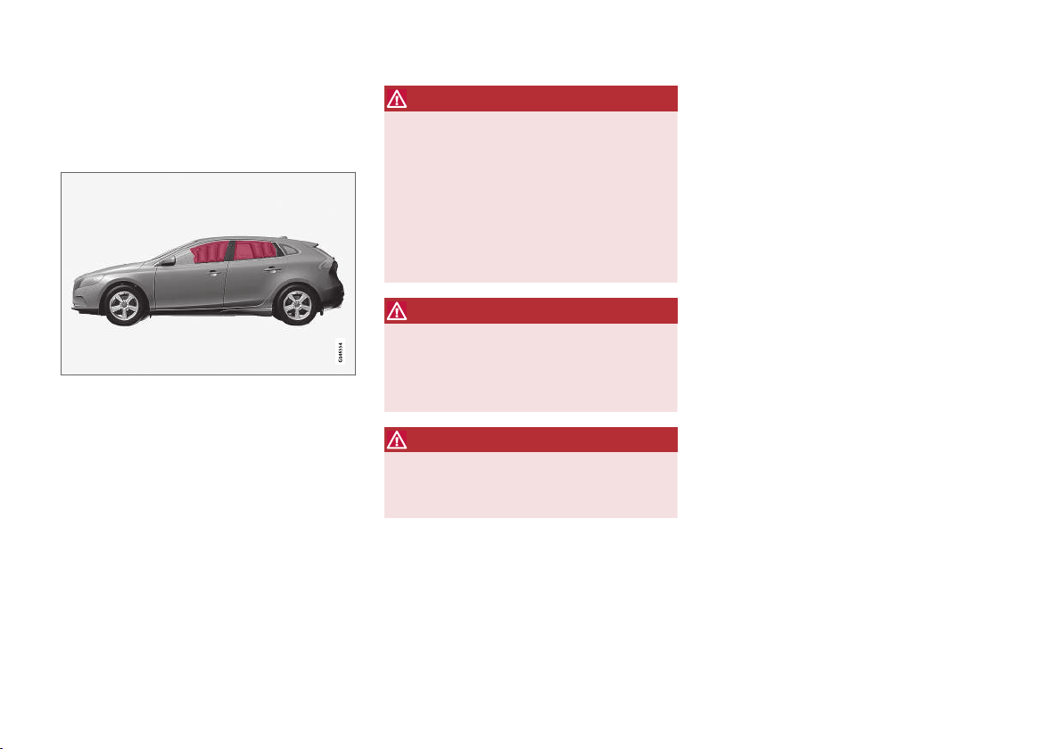
The inflatable curtain IC (Inflatable Curtain) is
part of the SIPS system (p. 38). It is fitted along
the headlining on both sides and helps protect
the driver and passengers in the car's outer
seats. A sufficiently violent collision trips the sensors and the inflatable curtain is inflated.
WARNING
Never hang or attach heavy items onto the
handles in the roof. The hook is only designed
for light clothing (not for solid objects such as
umbrellas for example).
Do not screw or install anything onto the car's
headlining, door pillars or side panels. This
could compromise the intended protection.
Volvo recommends that you only ever use
Volvo genuine parts that are approved for
placement in these areas.
WARNING
Do not load the car higher than 50 mm under
the top edge of the windows in the doors.
Otherwise, the intended protection of the
inflatable curtain, which is concealed in the
headlining, may be compromised.
WARNING
The inflatable curtain is a supplement to the
seatbelts.
Always use a seatbelt.
Related information
General information on seatbelts (p. 28)
•
Airbag system (p. 33)
•
Side airbag (SIPS) (p. 38)
•
General information on WHIPS (whiplash protection)
WHIPS (Whiplash Protection System) is a protection against whiplash injuries. The system
consists of energy absorbing backrests and
specially designed head restraints in the front
seats.
}}
39
Page 42
SAFETY
||
The WHIPS system is actuated by a rear-end collision, where the angle and speed of the collision,
and the nature of the colliding vehicle all have an
influence.
WARNING
The WHIPS system is a supplement to the
seatbelts. Always use a seatbelt.
Seat properties
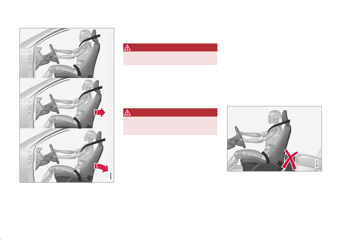
When the WHIPS system is deployed, the front
seat backrests are lowered backward to change
the seating position of the driver and front seat
passenger. This reduces the risk of whiplash
injury.
WARNING
Never modify or repair the seat or WHIPS
system yourself. Volvo recommends that you
contact an authorised Volvo workshop.
WHIPS and child seats
The protection provided by the car to children
seated in a child seat or on a booster cushion is
not diminished by the WHIPS system.
Related information
WHIPS - seating position (p. 40)
•
General information on seatbelts (p. 28)
•
WHIPS - seating position
In order to obtain optimum protection from the
WHIPS system (p. 39) the driver and passenger
must have the correct seating position and make
sure that the system's function is not obstructed.
Seating position
Set the correct seating position in the front seat
(p. 82) before driving starts.
Driver and front seat passenger should sit in the
centre of the seat with as little space as possible
between the head and the head restraint.
Function
Do not leave any objects on the floor behind the driver's
seat/passenger seat that may prevent the WHIPS system from functioning.
40
Page 43
SAFETY
WARNING
Do not squeeze rigid objects between the
rear seat cushion and the front seat's backrest. Make sure you do not to obstruct the
function of the WHIPS system.
Do not place objects on the rear seat that may prevent
the WHIPS system from functioning.
WARNING
If a backrest in the rear seat is lowered or a
rear-facing child seat is used in the rear seat,
the corresponding front seat must be moved
forward so that it does not make contact with
the lowered backrest or child seat.
WARNING
If a seat has been subjected to extreme
forces, such as due to a rear-end collision, the
WHIPS system must be checked. Volvo recommends that it is checked by an authorised
Volvo workshop.
Part of the WHIPS system's protective
capacity may have been lost even if the seat
appears to be undamaged.
Volvo recommends that you contact an
authorised Volvo workshop to have the system checked even after a minor rear-end collision.
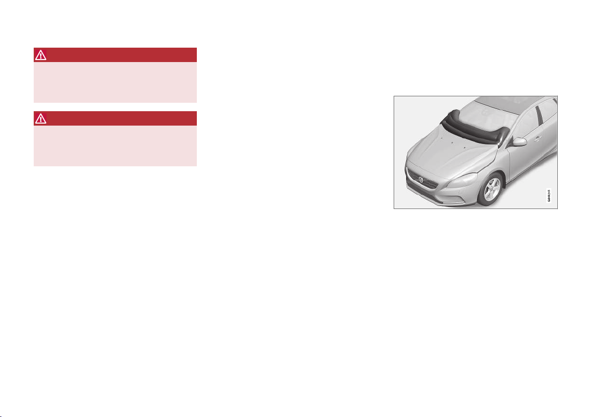
General information on safety mode
Safety mode is a protective state that is triggered when a collision may have damaged any
of the car's vital functions, such as the fuel lines,
sensors for any of the safety systems, or the
brake system.
Warning triangle in the analogue combined instrument
panel.
}}
41
Page 44
SAFETY
||
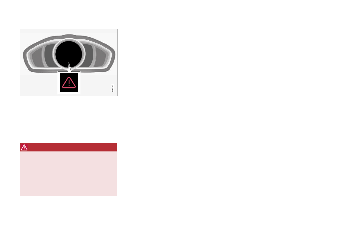
Warning triangle in the digital combined instrument
panel.
If the car is involved in a collision, the text Safety
mode See manual may appear in the combined
instrument panel (p. 66) information display.
This means that the car has reduced functionality.
WARNING
Never attempt to repair your car or reset the
electronics yourself if the car has been in
safety mode. This could result in personal
injury or the car not functioning as normal.
Volvo recommends that you engage an
authorised Volvo workshop to check and
restore the car to normal status after
mode See manual
has been displayed.
Safety
Related information
Safety mode - attempting to start the car
•
(p. 42)
Safety mode - moving the car (p. 43)
•
Safety mode - attempting to start
the car
If the car is set in safety mode (p. 41) then an
attempt to start the car can be made if everything seems normal and the absence of fuel
leakage has been checked.
First, check that no fuel is leaking from the car.
There must be no smell of fuel either.
If everything seems normal and you have
checked for indications of fuel leakage, you may
attempt to start the car.
Remove the remote control key and open the
driver's door. If a message is now shown to the
effect that the ignition is on, press the start button. Then close the door and reinsert the remote
control key. The car's electronics will now try to
reset themselves to normal mode. Then try to
start the car.
If the message Safety mode See manual is
still shown on the display, then the car must not
be driven or towed, but a vehicle recovery service
(p. 312) must be used instead. Even if the car
appears to be driveable, hidden damage may
make the car impossible to control once moving.
42
Page 45
SAFETY
WARNING
Never, under any circumstances, attempt to
restart the car if it smells of fuel when the
Safety mode See manual message is dis-
played. Leave the car at once.
WARNING
If the car is in safety mode it must not be
towed. It must be transported from its location. Volvo recommends that it is transported
to an authorised Volvo workshop.
Related information
Safety mode - moving the car (p. 43)
•
Safety mode - moving the car
Normal mode is shown after Safety mode
If
See manual has been reset after attempting to
start the car (p. 42) , the car can be moved carefully out of a dangerous position.
Do not move the car further than necessary.
Related information
General information on safety mode (p. 41)
•
Pedestrian airbag
The airbag for pedestrians (Pedestrian Airbag)
contributes in certain frontal collisions to alleviating the collision of the pedestrian with the car.
The pedestrian airbag (Pedestrian Airbag) is fitted under the bonnet near the windscreen. In the
event of certain frontal collisions with a pedestrian, the sensors in the front bumper react and
the airbag inflates if required, based on the force
of the impact. The sensors are active at a speed
of approx. 20-50 km/h (12-30 mph) and an
ambient temperature between -20 and +70°C.
The sensors are designed to detect a collision
with an object that has similar properties to those
of the human leg.
}}
43
Page 46
SAFETY
||
NOTE
There may be objects in the traffic environment that prompt a signal to the sensors that
is similar to a collision with a pedestrian. It is
possible that the system will be activated in
the event of a collision with such an object.
If the airbag is activated (Pedestrian Airbag)
the rear part of the bonnet is raised and
•
locked in this position
the hazard warning flashers are activated
•
the brake system is prepared for the upcom-
•
ing emergency braking.
WARNING
Do not fit any accessories or change anything
in the front. Incorrect intervention at the front
may cause incorrect function in the system
and lead to serious injury and damage to the
car.
Volvo recommends that genuine wiper arms
are used and that you only use genuine parts
for them.
WARNING
Volvo recommends contacting an authorised
Volvo workshop in the event of damage to the
bumper in order to ensure that the system is
intact.
Related information
Pedestrian airbag - moving the car (p. 44)
•
Pedestrian airbag - folding up (p. 45)
•
Pedestrian airbag - moving the car
The car may be moved if it has not been set in
safety mode (p. 41).
If any of the other airbags in the passenger compartment were activated then the car remains in
safety mode.
If only the pedestrian airbag (p. 43) (Pedestrian
Airbag) has been activated:
1. Move the car to a safe location as close as
possible.
2. Fold up the airbag in accordance with the
instructions (p. 45).
3. Seek the nearest workshop.
WARNING
Volvo recommends that, after activation of the
airbag, you contact an authorised Volvo workshop as soon as possible.
Related information
Pedestrian airbag (p. 43)
•
44
Page 47
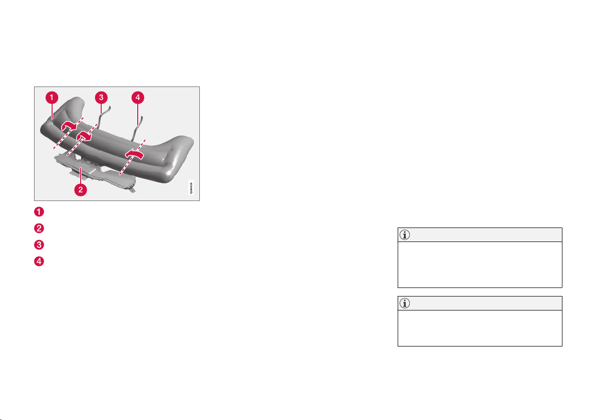
SAFETY
Pedestrian airbag - folding up
Pedestrian airbag (p. 43) (Pedestrian Airbag)
must be folded up before the car is moved.
Airbag
Airbag housing
Velcro strap, right-hand side
Velcro strap, left-hand side
The airbag may feel warm and give off smoke.
This is normal. Fold the airbag as follows:
1. Find the Velcro strap on the
left-hand side (4).
2. Gather the airbag fabric along its length on
the left-hand side. Then fold the gathered
fabric towards the centre. Wind the Velcro
strap (double sided) around as much fabric
as possible and fasten it.
3. Press the rolled up portion of the airbag into
the airbag housing (2).
4. Repeat points 1-3 for the right-hand side. It
may be necessary to fold the gathered fabric
twice on this side in order to wind the Velcro
strap around it.
5. The airbag housing cover will be open
slightly. This is completely normal.
Related information
Pedestrian airbag - moving the car (p. 44)
•
General information on child safety
Volvo has child safety equipment (child seats,
booster cushions & attachment devices) which
is designed for fitting in this particular car.
Using Volvo's child safety equipment, the optimum conditions are obtained for the child to
travel safely in the car. In addition, the child safety
equipment fits well and is simple to use.
Children of all ages and sizes must always sit
correctly secured in the car. Never allow a child to
sit on the knee of a passenger.
Volvo recommends that children travel in rearfacing child seats until as late an age as possible,
at least up to 3-4 years of age, and then in frontfacing booster cushions/child seats until the
child is 140 cm tall.
NOTE
Legal provisions about the type of child seat
that must be used for children of different
ages and heights vary from country to country. Check what does apply.
NOTE
In the event of questions when fitting child
safety products, contact the manufacturer for
clearer instructions.
}}
45
Page 48

SAFETY
||
Child safety locks
The controls for operating the rear door power
windows and the rear door opening handles can
be blocked (p. 176) from opening from the
inside.
Related information
Child seats (p. 47)
•
Child seats - location (p. 52)
•
Child seat - ISOFIX (p. 53)
•
Child seats - upper mounting points (p. 57)
•
46
Page 49
SAFETY
Child seats
Children should sit comfortably and safely. Make
sure that the child seat is being used correctly.
NOTE
When using child safety products it is important to read the installation instructions
included.
NOTE
Never leave a child seat loose in the car.
Always secure it according to the instructions
for the child seat, even when it is not in use.
WARNING
Do not secure the straps of the child seat to
the seat's horizontal adjustment bar, springs
or the rails and beams under the seat. Sharp
edges may damage the straps.
Look in the installation instructions for the child
seat for the correct fitting.
}}
47
Page 50

SAFETY
||
Recommended child seats
Weight Front seat (with deactivated air-
bag, only rear-facing child seats)
Group 0
max 10 kg
Group 0+
max 13 kg
Group 0
max 10 kg
Group 0+
max 13 kg
Group 0
max 10 kg
Group 0+
Volvo infant seat (Volvo Infant
Seat) - rear-facing child seat,
secured with the car's seatbelt.
Type approval: E1 04301146
(U)
Child seats which are universally
approved.
A
(U)
max 13 kg
1
Front seat (with activated air-
Outer rear seat Centre rear seat
bag, only front-facing child
seats)
Volvo infant seat (Volvo Infant Seat) - rear-
facing child seat, secured with the ISOFIX fix-
ture system.
Type approval: E1 04301146
(L)
Volvo infant seat (Volvo Infant Seat) - rear-
facing child seat, secured with the car's seat-
belt.
Type approval: E1 04301146
(U)
Volvo infant seat
(Volvo Infant Seat) rear-facing child seat,
secured with the car's
seatbelt.
Type approval: E1
04301146
(U)
Child seats which are universally approved.
(U)
1
With regard to other child seats your car should be included in the manufacturer's enclosed list of vehicles or be universally approved in accordance with the ECE R44 legal requirement.
48
Page 51

SAFETY
Weight Front seat (with deactivated air-
bag, only rear-facing child seats)
Group 1
9-18 kg
Volvo turnable child seat (Volvo
Convertible Child Seat) – rear-facing child seat, secured with the
car's seatbelt and straps.
Type approval: E5 04192
(L)
Group 1
9-18 kg
Volvo rear-facing child seat
Type approval: E5 04212
(L)
Group 1
9-18 kg
Group 2
15-25 kg
Volvo turnable child seat (Volvo
Convertible Child Seat) – rear-facing child seat, secured with the
car's seatbelt and straps.
Type approval: E5 04192
(L)
Group 2
15-25 kg
Volvo rear-facing child seat
Type approval: E5 04212
(L)
Front seat (with activated airbag, only front-facing child
seats)
Front-facing child seats which
are universally approved.
A, B
(UF)
Outer rear seat Centre rear seat
Volvo turnable child seat (Volvo Convertible
Child Seat) – rear-facing child seat, secured
with the car's seatbelt and straps.
Type approval: E5 04192
(L)
Volvo rear-facing child seat
Type approval: E5 04212
(L)
Child seats which are universally approved.
(U)
Volvo turnable child seat (Volvo Convertible
Child Seat) – rear-facing child seat, secured
with the car's seatbelt and straps.
Type approval: E5 04192
(L)
Volvo rear-facing child seat
Type approval: E5 04212
(L)
}}
49
Page 52
SAFETY
||
Weight Front seat (with deactivated air-
bag, only rear-facing child seats)
Group 2
15-25 kg
Group 2/3
15-36 kg
Group 2/3
15-36 kg
Front seat (with activated airbag, only front-facing child
seats)
Volvo turnable child seat (Volvo
Convertible Child Seat) - frontfacing child seat, secured with
the car's seatbelt.
Type approval: E5 04191
(U)
Volvo booster seat with backrest (Volvo Booster Seat with
backrest).
Type approval: E1 04301169
(UF)
Volvo booster seat
Type approval: E1 04301312
(UF)
Outer rear seat Centre rear seat
Volvo turnable child seat (Volvo Convertible
Child Seat) - front-facing child seat, secured
with the car's seatbelt.
Type approval: E5 04191
(U)
Volvo booster seat with backrest (Volvo
Booster Seat with backrest).
Type approval: E1 04301169
(UF)
Volvo booster seat
Type approval: E1 04301312
(UF, L)
50
Page 53
SAFETY
Weight Front seat (with deactivated air-
bag, only rear-facing child seats)
Front seat (with activated airbag, only front-facing child
Outer rear seat Centre rear seat
seats)
Group 2/3
15-36 kg
Booster cushion with and without backrest (Booster Cushion
with and without backrest).
Type approval: E5 04216
Booster cushion with and without backrest
(Booster Cushion with and without backrest).
Type approval: E5 04216
(UF)
(UF)
L: Suitable for specific child seats. These child seats may be intended for use in a special car model, limited or semi-universal categories.
U: Suitable for universally approved child seats in this weight class.
UF: Suitable for front-facing universally approved child seats in this weight class.
B: Built-in child seats approved for this weight class.
A
Only for rear-facing child seat. Set the seat's backrest in upright position.
B
Volvo recommends rear-facing child seat for children in this mass group.
Related information
Child seats - location (p. 52)
•
Child seats - upper mounting points (p. 57)
•
Child seat - ISOFIX (p. 53)
•
General information on child safety (p. 45)
•
51
Page 54
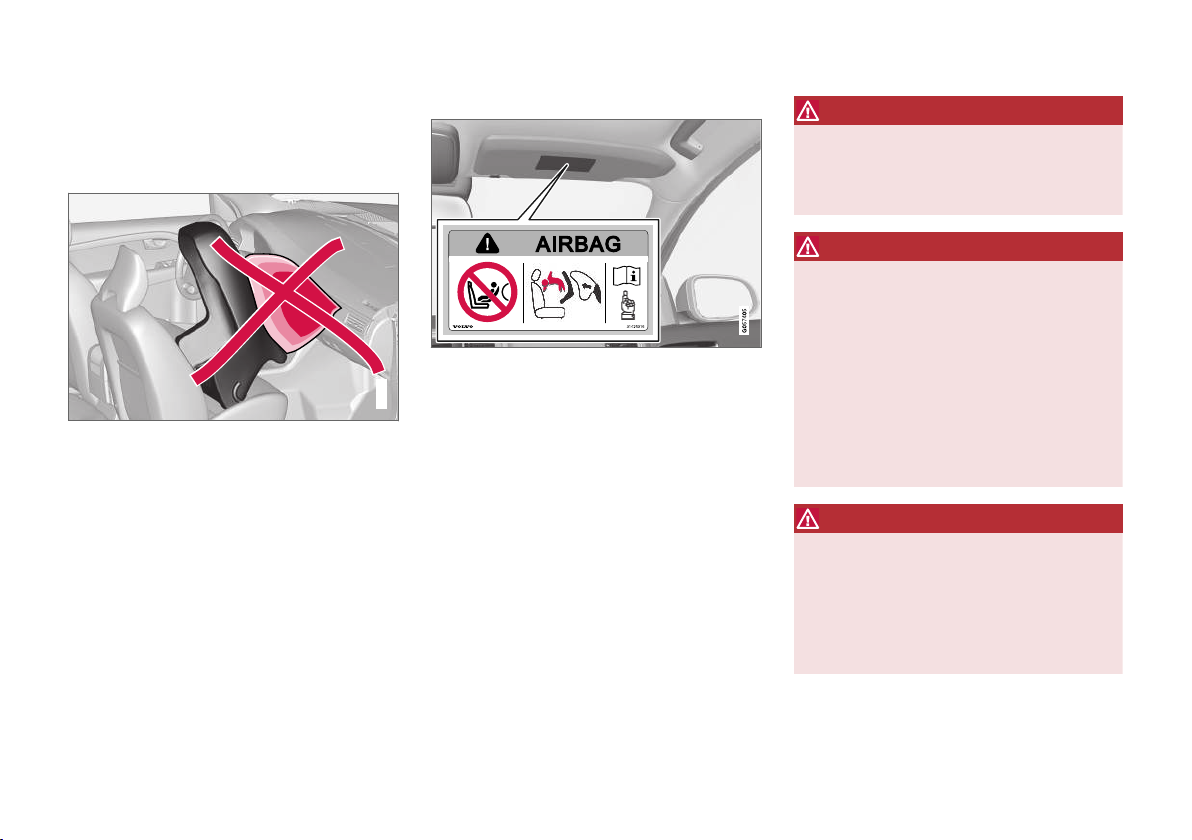
SAFETY
G020739
Child seats - location
The position of a child in the car and the choice
of equipment are dictated by the child's weight
and size.
Rear-facing child seat and airbag are not compatible.
Always fit rear-facing child seats (p. 47) in the
rear seat if the passenger airbag is activated
(p. 36). If a child is sitting on the front passenger
seat then he/she could suffer serious injury if the
airbag deploys.
If the passenger airbag is deactivated then rearfacing child seats can be fitted on the front passenger seat.
Label for passenger airbag
Label on the passenger side's sun visor.
The warning label for the passenger airbag is
positioned as shown above.
You may place:
a rear-facing child seat on the front passen-
•
ger seat when the passenger airbag is deactivated.
a front-facing child seat/booster cushion on
•
the front passenger seat when the passenger airbag is activated.
one or more child seats/booster cushions in
•
the rear seat.
WARNING
Never use a rear-facing child seat on a seat
protected by an activated airbag. Failure to
follow this advice can lead to death or serious
injury to the child.
WARNING
Never allow anybody to stand or sit in front of
the front passenger seat.
Never use a rear-facing child seat on the front
passenger seat if the passenger airbag is
activated.
Front-facing passengers (children and adults)
must never sit on the front passenger seat if
the passenger airbag is deactivated.
Failure to follow the advice given above can
endanger life or lead to serious personal
injury.
WARNING
Booster cushions/child seats with steel
braces or some other design that could rest
on the seatbelt buckle's opening button must
not be used, as they could cause the seatbelt
buckle to open accidentally.
Do not allow the upper section of the child
seat to rest against the windscreen.
52
Page 55
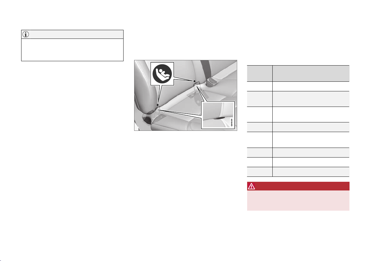
SAFETY
NOTE
Regulations regarding the placement of children in cars vary from country to country.
Check what does apply.
Related information
General information on child safety (p. 45)
•
Child seats - upper mounting points (p. 57)
•
Child seat - ISOFIX (p. 53)
•
Child seat - ISOFIX
ISOFIX is a fixture system for car child seats
(p. 47) that is based on an international standard.
Mounting points for the ISOFIX fixture system are
located at the lower section of the rear seat
backrest, in the outer seats.
The location of the mounting points is indicated
by symbols in the backrest upholstery (see preceding illustration).
Always follow the manufacturer's installation
instructions when connecting a child seat to the
ISOFIX mounting points.
Related information
ISOFIX - size classes (p. 53)
•
ISOFIX - types of child seat (p. 55)
•
General information on child safety (p. 45)
•
ISOFIX - size classes
There is a size classification for child seats using
the ISOFIX (p. 53) fixture system in order to
assist users in choosing the correct type of child
seat (p. 55).
Size
class
Never use a rear-facing child seat on the passenger seat if the passenger airbag is activated.
Description
A Full size, front-facing child seat
B Reduced size (alt. 1), front-facing
child seat
B1 Reduced size (alt.2), front-facing
child seat
C Full size, rear-facing child seat
D Reduced size, rear-facing child
seat
E Rear-facing infant seat
F Transverse infant seat, left-hand
G Transverse infant seat, right-hand
WARNING
}}
53
Page 56
SAFETY
||
NOTE
If an ISOFIX child seat has no size classification, the car model must be included on the
vehicle list for the child seat.
NOTE
Volvo recommends that you contact an
authorised Volvo dealer for recommendations
about which ISOFIX child seats Volvo recommends.
Related information
ISOFIX - types of child seat (p. 55)
•
54
Page 57

ISOFIX - types of child seat
Child seats are in different sizes – cars are in different sizes. This means that not all child seats
are suitable for all seats in all car models.
Type of child seat Weight Size class
Infant seat transverse max 10 kg F X X
G X X
Infant seat, rear-facing max 10 kg E X OK
Infant seat, rear-facing max 13 kg E X OK
D X OK
C X OK
Child seat, rear-facing 9-18 kg D X OK
C X OK
Passenger seats for ISOFIXA installation of child seats
Front seat Outer rear seat
SAFETY
(IL)
(IL)
(IL)
(IL)
(IL)
(IL)
}}
55
Page 58
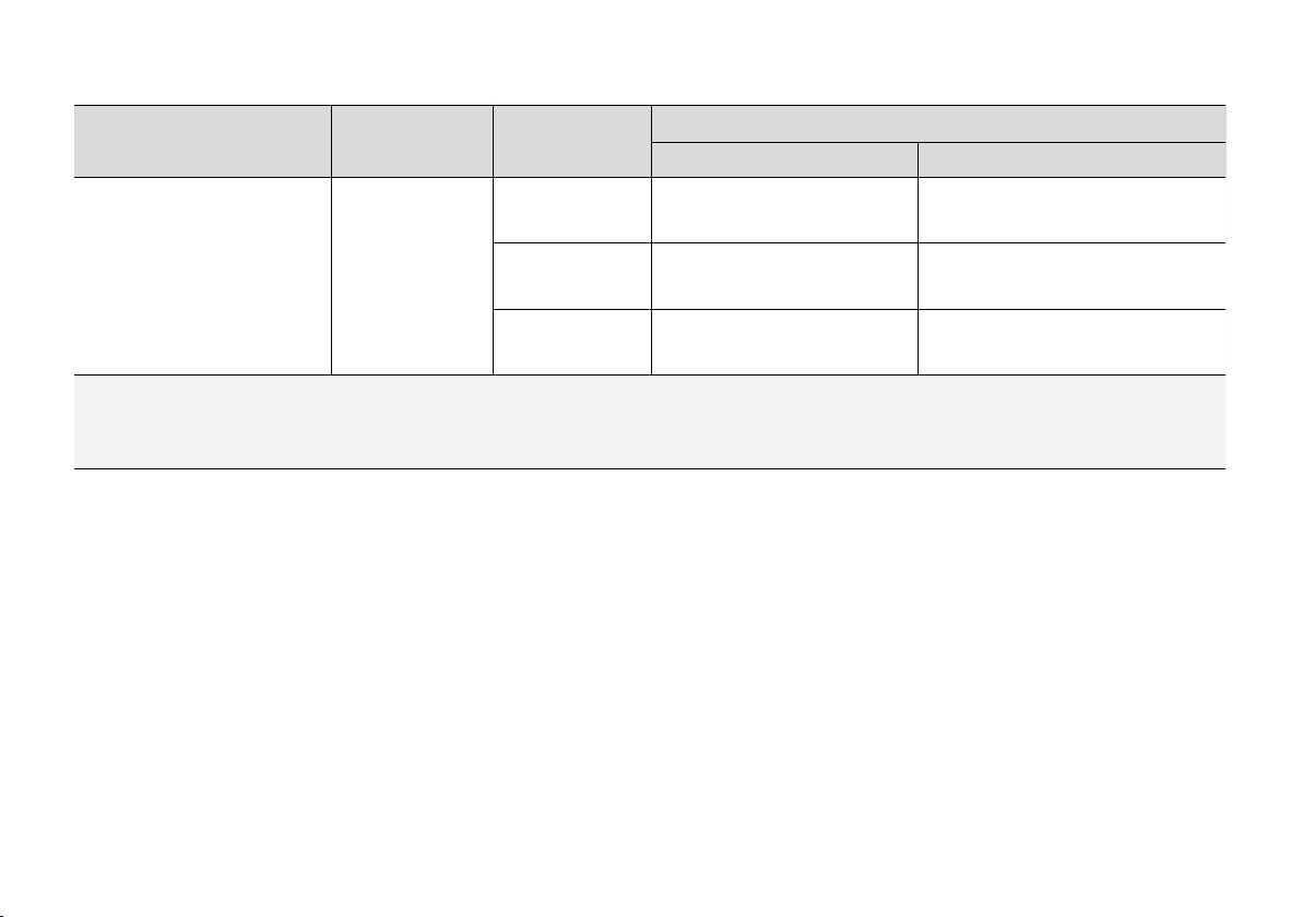
SAFETY
||
Type of child seat Weight Size class
Passenger seats for ISOFIXA installation of child seats
Front seat Outer rear seat
Front-facing child seat 9-18 kg B X
B1 X
A X
X: The ISOFIX position is not suitable for ISOFIX child seats in this weight class and/or size class.
IL: Suitable for specific ISOFIX child seats. These child seats may be intended for a particular car model, limited or semi-universal categories.
IUF: Suitable for front-facing ISOFIX child seats that are universally approved in this weight class.
A
ISOFIX is a fixture system for car child seats that is based on an international standard.
B
Volvo recommends rear-facing child seats for this group.
Make sure you select the right size class (p. 53)
of child seat with ISOFIX fixture system.
Related information
Child seat - ISOFIX (p. 53)
•
OK
(IUF)
OK
(IUF)
OK
(IUF)
B
B
B
56
Page 59
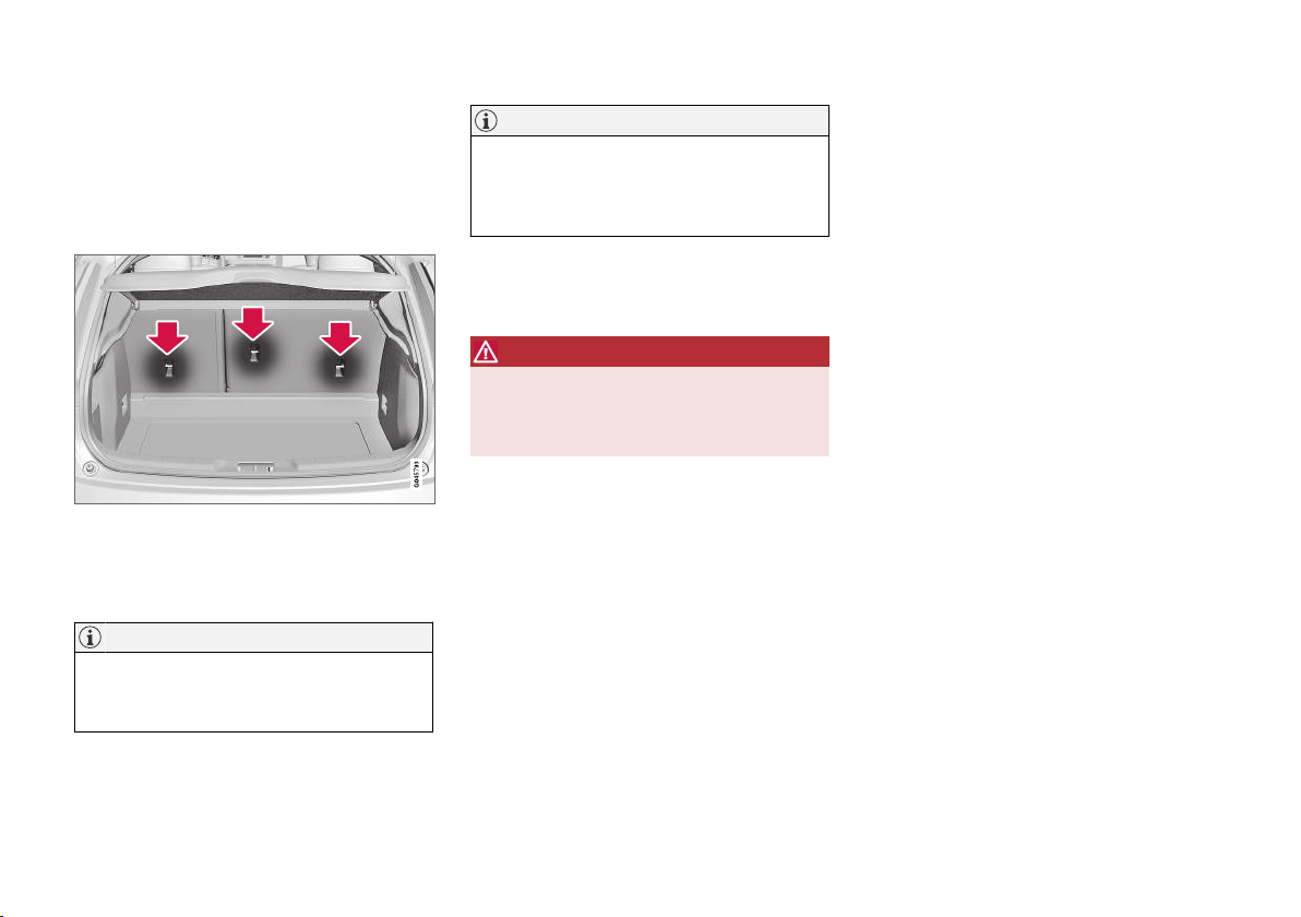
SAFETY
Child seats - upper mounting points
The car is equipped with upper mounting points
for certain front-facing child seats (p. 47). These
mounting points are located on the rear of the
seat.
Upper mounting points
The upper mounting points are primarily intended
for use with front-facing child seats. Volvo recommends that small children should sit in rear-facing child seats to as late an age as possible.
NOTE
Fold the head restraints in order to facilitate
fitting this type of child seat in cars with folding head restraints on the outer seats.
NOTE
In cars with a cargo cover over the luggage
compartment, this must be removed before
child seats can be attached to the securing
points.
For detailed information on how the child seat
should be tensioned in the upper mounting
points, see the seat manufacturer's instructions.
WARNING
The child seat's straps must always be drawn
through the hole in the head restraint leg
before they are tensioned at the attachment
point.
Related information
General information on child safety (p. 45)
•
Child seats - location (p. 52)
•
Child seat - ISOFIX (p. 53)
•
57
Page 60

Page 61

INSTRUMENTS AND CONTROLS
Page 62

INSTRUMENTS AND CONTROLS
Instruments and controls, left-hand drive car - overview
The overview shows where the car's displays
and controls are located.
60
Page 63
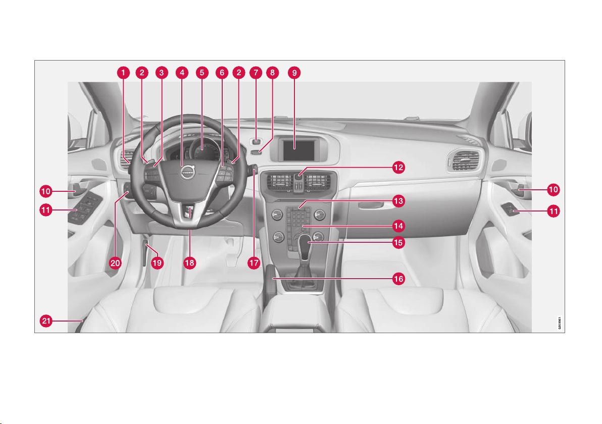
Overview, left-hand drive cars
INSTRUMENTS AND CONTROLS
}}
61
Page 64
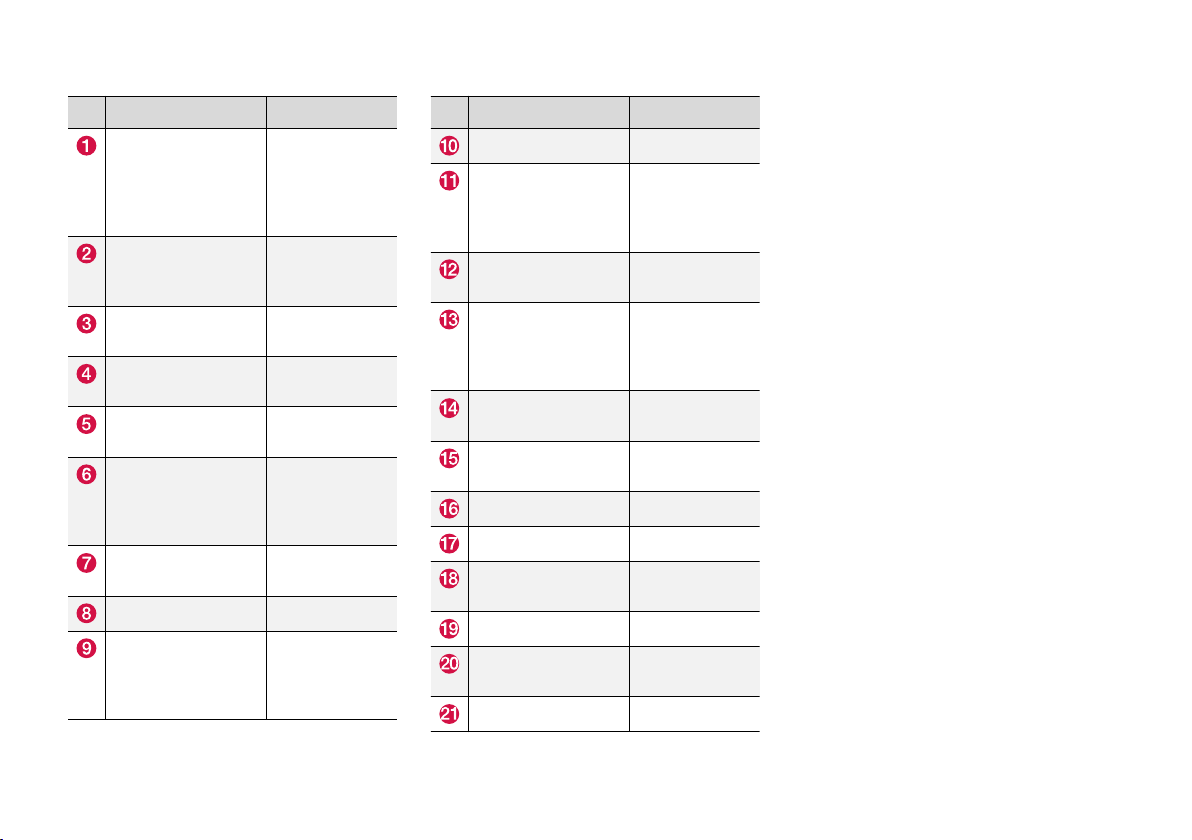
INSTRUMENTS AND CONTROLS
||
Function See
Menus and messages, direction indicators, main/dipped
beam, trip computer
Manual gear changing in an automatic
gearbox*
Cruise control*
Horn, airbags (p. 87) and
Combined instrument
panel
Menu navigation,
audio control, phone
control*
START/STOP
ENGINE button
Ignition switch (p. 80).
Screen for infotainment and display of
menus
(p. 110),
(p. 113),
(p. 99),
(p. 91) and
(p. 114).
(p. 272).
(p. 192) and
(p. 201).
(p. 33).
(p. 66).
(p. 113) and the
Sensus Infotainment supplement.
(p. 268).
(p. 113) and the
Sensus Infotainment supplement.
Function See
Door handle –
Control panel (p. 171),
Hazard warning
flashers
Control panel for
infotainment system
and menu navigation
Control panel for climate control
Gear selector (p. 271) or
Parking brake (p. 289).
Wipers and washing (p. 102).
Steering wheel
adjustment
Bonnet opener (p. 341).
Light switch, opener
for tailgate
Seat adjustment*
(p. 176),
(p. 104) and
(p. 106).
(p. 99).
(p. 113) and the
Sensus Infotainment supplement.
(p. 127) or
(p. 128).
(p. 272).
(p. 87).
(p. 88) and
(p. 172).
(p. 84).
Related information
Outside temperature gauge (p. 75)
•
Trip meter (p. 75)
•
Clock (p. 75)
•
62
* Option/accessory.
Page 65

Instruments and controls, righthand drive car - overview
The overview shows where the car's displays
and controls are located.
INSTRUMENTS AND CONTROLS
}}
63
Page 66
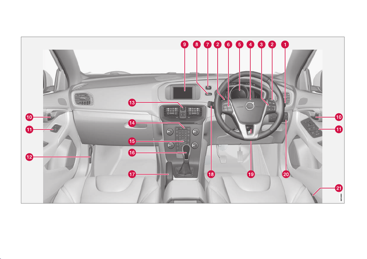
INSTRUMENTS AND CONTROLS
||
Overview, right-hand drive cars
64
Page 67
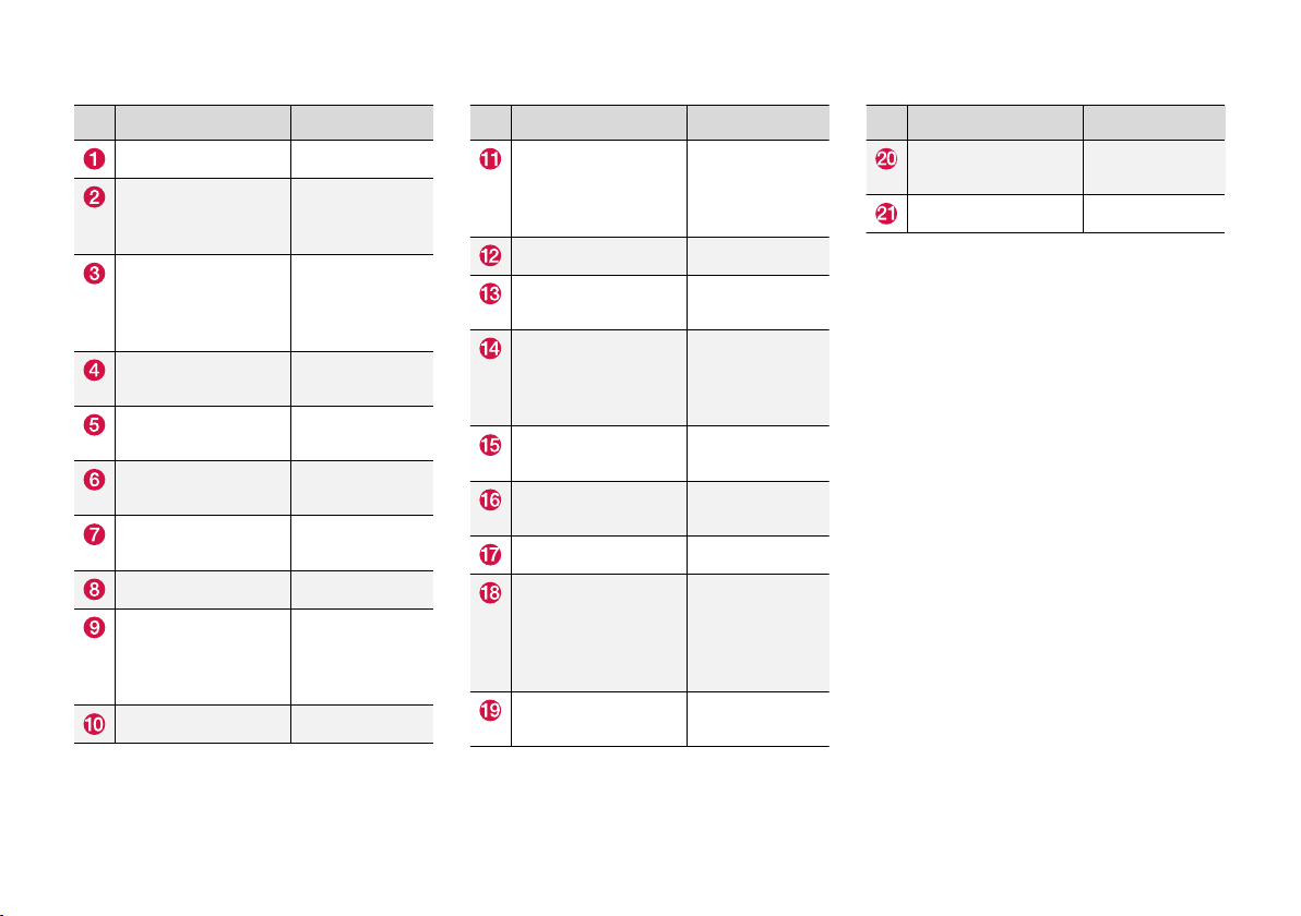
INSTRUMENTS AND CONTROLS
Function See
Wipers and washing (p. 102).
Manual gear changing in an automatic
gearbox*
Menu navigation,
audio control, phone
control*
Horn, airbags (p. 87) and
Combined instrument
panel
Cruise control*
START/STOP
ENGINE button
Ignition switch (p. 80).
Screen for infotainment and display of
menus
Door handle –
(p. 272).
(p. 113) and the
Sensus Infotainment supplement.
(p. 33).
(p. 66).
(p. 192) and
(p. 201).
(p. 268).
(p. 113) and the
Sensus Infotainment supplement.
Function See
Control panel (p. 171),
Bonnet opener (p. 341).
Hazard warning
flashers
Control panel for
infotainment system
and menu navigation
Control panel for climate control
Gear selector (p. 271) or
Parking brake (p. 289).
Menus and messages, direction indicators, main/dipped
beam, trip computer
Steering wheel
adjustment
(p. 176),
(p. 104) and
(p. 106).
(p. 99).
(p. 113) and the
Sensus Infotainment supplement.
(p. 127) or
(p. 128).
(p. 272).
(p. 110),
(p. 113),
(p. 99),
(p. 91) and
(p. 114).
(p. 87).
Function See
Light switch, opener
for tailgate
Seat adjustment*
Related information
Outside temperature gauge (p. 75)
•
Trip meter (p. 75)
•
Clock (p. 75)
•
(p. 88) and
(p. 172).
(p. 84).
* Option/accessory.
65
Page 68
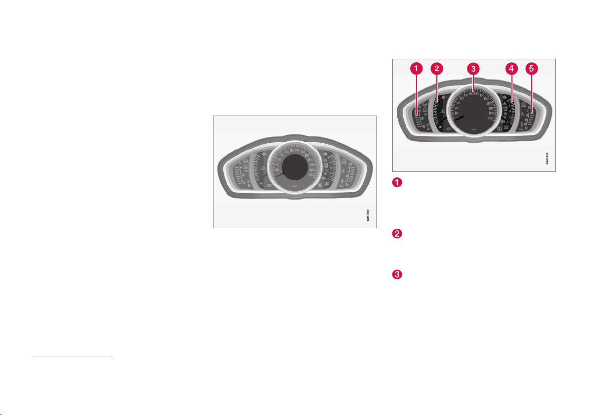
INSTRUMENTS AND CONTROLS
Combined instrument panel
The combined instrument panel's information
display shows information on some of the car's
functions, as well as messages.
Analogue combined instrument panel - over-
•
view (p. 66)
Digital combined instrument panel - overview
•
(p. 67)
Combined instrument panel - meaning of
•
indicator symbols (p. 71)
Combined instrument cluster - meaning of
•
warning symbols (p. 73)
Analogue combined instrument panel - overview
The combined instrument panel's information
display shows information on some of the car's
functions, as well as messages.
Information display
Information display, analogue instrument panel.
There are further descriptions under the functions that use the display.
Gauges and indicators
Fuel gauge. When the indicator lowers to
only one white marking1, the yellow indicator
symbol for low level in the fuel tank is illuminated. See also Trip computer (p. 114) and
Filling up with fuel (p. 294).
Eco meter The meter provides an indication
of how economically the car is being driven.
The higher the reading on the scale, the
more economically the car is driven.
Speedometer
1
When the display's message
66
Distance to empty fuel tank: starts to show ----, the marking becomes red.
Page 69
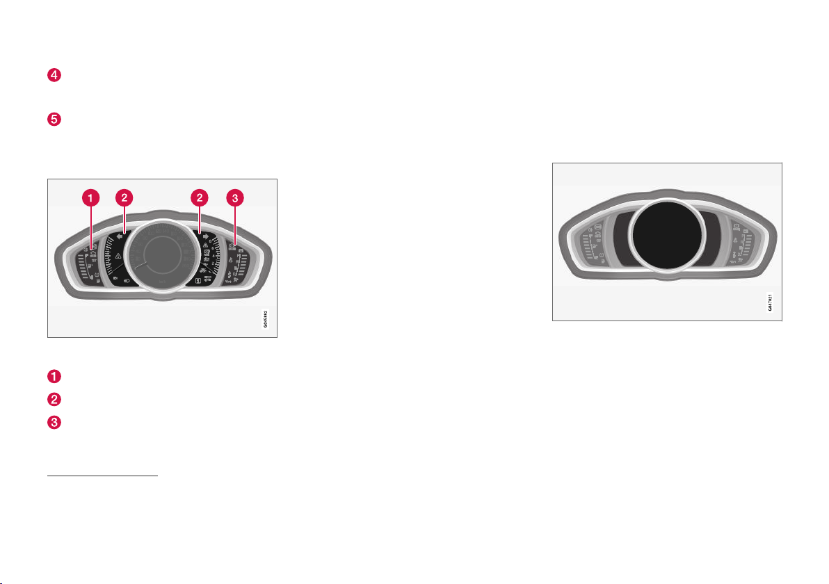
INSTRUMENTS AND CONTROLS
Tachometer. The meter indicates engine
speed in thousands of revolutions per minute
(rpm).
Gear shift indicator2 / Gear position indicator3. See also Gear shift indicator* (p. 272)
or Automatic gearbox - Geartronic* (p. 272).
Indicator and warning symbols
Indicator and warning symbols, analogue instrument
panel.
Indicator symbols
Indicator and warning symbols
Warning symbols
4
Functionality check
All indicator and warning symbols, apart from
symbols in the centre of the information display,
illuminate in key position II or when the engine is
started. When the engine has started, all the
symbols should go out except the parking brake
symbol, which only goes out when the brake is
disengaged.
If the engine does not start or if the functionality
check is carried out in key position II then all
symbols go out within a few seconds except the
symbol for faults in the car's emissions system
and the symbol for low oil pressure.
Related information
Combined instrument panel (p. 66)
•
Combined instrument panel - meaning of
•
indicator symbols (p. 71)
Combined instrument cluster - meaning of
•
warning symbols (p. 73)
Digital combined instrument panel - overview
•
(p. 67)
Digital combined instrument panel overview
The combined instrument panel's information
display shows information on some of the car's
functions, as well as messages.
Information display
Information display, digital instrument panel*.
There are further descriptions under the functions that use the display.
Gauges and indicators
Various themes can be selected for the digital
combined instrument panel. Possible themes are
"Elegance", "Eco" and "Performance".
2
Manual gearbox.
3
Automatic gearbox.
4
Certain engine variants do not have systems to warn of oil pressure loss. In cars with these variants the symbol for low oil pressure is not used. Warning for low oil level is via display text. For more information, see
Engine oil - general (p. 342).
* Option/accessory.
}}
67
Page 70
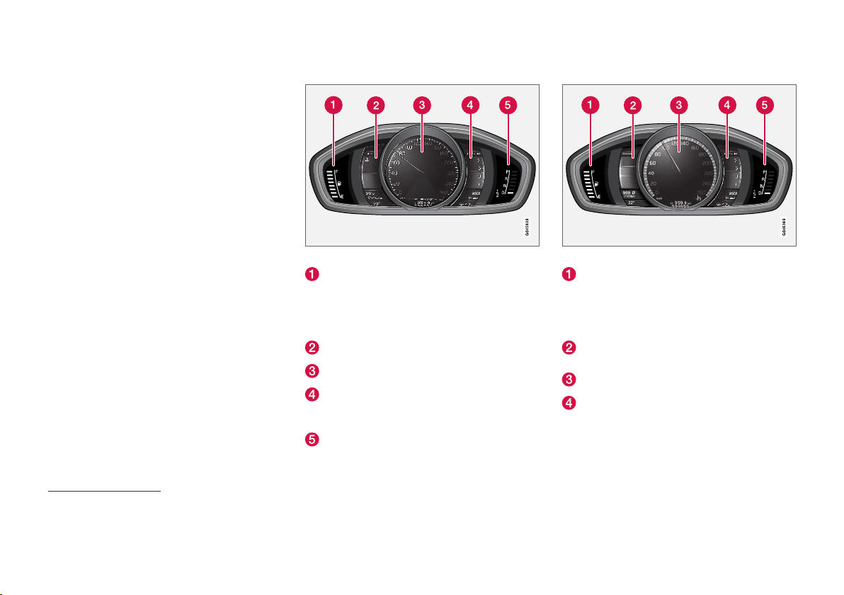
INSTRUMENTS AND CONTROLS
A theme can only be selected when the engine is
||
running.
To select the theme, press the left-hand stalk
switch's OK button and select the
Themes
menu option by turning the thumbwheel on the
lever. Press the OK button. Turn the thumbwheel
to select the theme and confirm the selection by
pressing the OK button.
On certain model variants, the appearance of the
centre console's screen follows the theme
selected for the combined instrument panel.
The contrast mode and colour mode for the
instrument can also be set using the left-hand
stalk switch.
For more information on menu navigation, see
Menu navigation - combined instrument panel
(p. 110).
The choice of theme and setting of contrast
mode and colour mode can be stored for each
remote control key in the car key memory*, see
Remote control key - personalisation* (p. 157).
Theme "Elegance"
Gauges and indicators, theme "Elegance".
Fuel gauge. When the indicator lowers to
only one white marking5, the yellow indicator
symbol for low level in the fuel tank is illuminated. See also Trip computer (p. 114) and
Filling up with fuel (p. 294).
Temperature gauge for engine coolant
Speedometer
Tachometer. The meter indicates engine
speed in thousands of revolutions per minute
(rpm).
Gear shift indicator6 / Gear position indicator7. See also Gear shift indicator* (p. 272)
or Automatic gearbox - Geartronic* (p. 272).
Theme "Eco"
Gauges and indicators, theme "Eco".
Fuel gauge. When the indicator lowers to
only one white marking5, the yellow indicator
symbol for low level in the fuel tank is illuminated. See also Trip computer (p. 114) and
Filling up with fuel (p. 294).
Eco guide. See also Eco guide & Power
guide* (p. 70).
Speedometer
Tachometer. The meter indicates engine
speed in thousands of revolutions per minute
(rpm).
5
When the display's message
6
Manual gearbox.
7
Automatic gearbox.
68
Distance to empty fuel tank: starts to show ----, the marking becomes red.
* Option/accessory.
Page 71
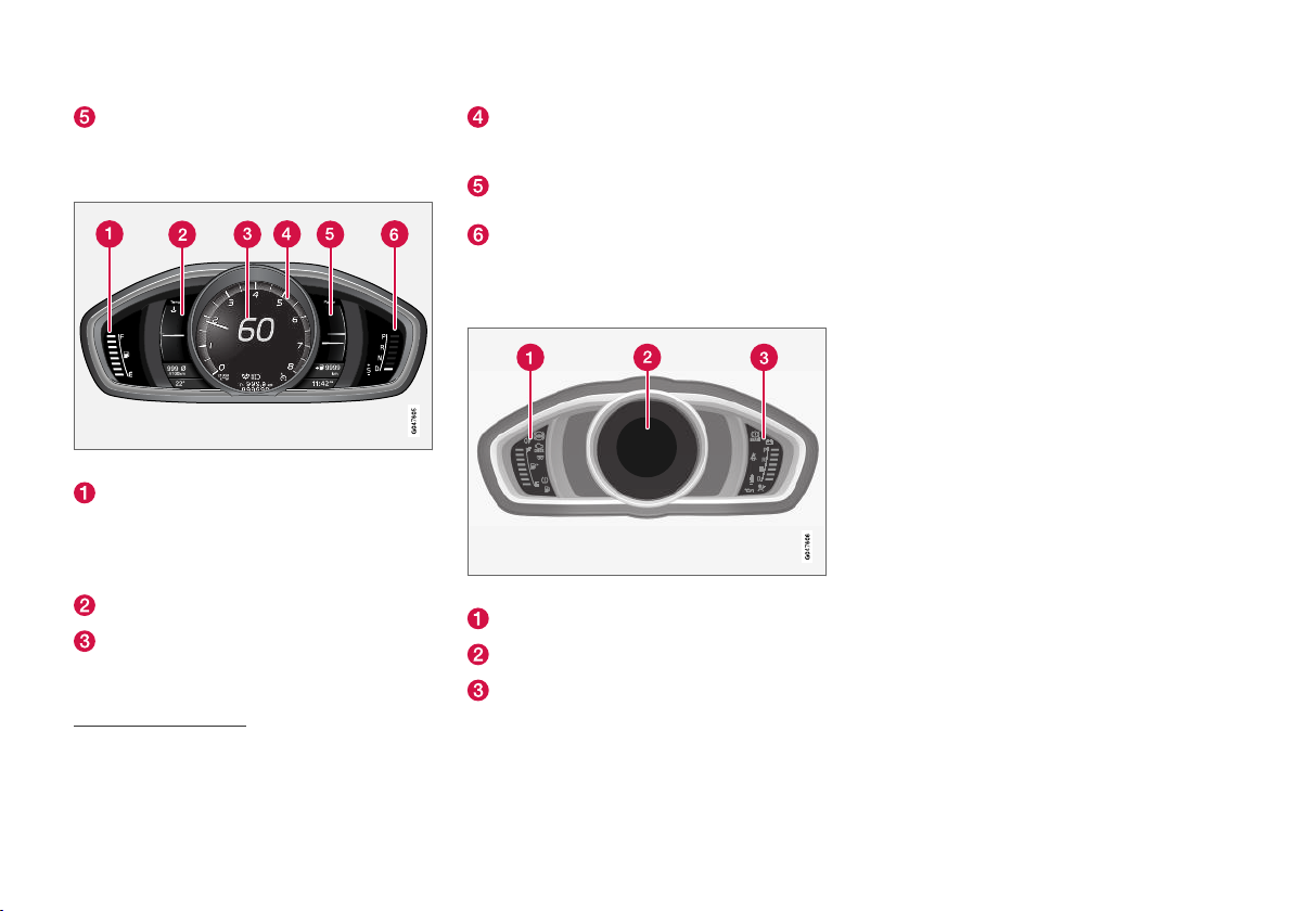
INSTRUMENTS AND CONTROLS
Gear shift indicator6 / Gear position indicator7. See also Gear shift indicator* (p. 272)
or Automatic gearbox - Geartronic* (p. 272).
Theme "Performance"
Tachometer. The meter indicates engine
speed in thousands of revolutions per minute
(rpm).
Power guide. See also Eco guide & Power
guide* (p. 70).
Gear shift indicator6 / Gear position indicator7. See also Gear shift indicator* (p. 272)
or Automatic gearbox - Geartronic* (p. 272).
Indicator and warning symbols
Functionality check
All indicator and warning symbols, apart from
symbols in the centre of the information display,
illuminate in key position II or when the engine is
started. When the engine has started, all the
symbols should go out except the parking brake
symbol, which only goes out when the brake is
disengaged.
If the engine does not start or if the functionality
check is carried out in key position II then all
symbols go out within a few seconds except the
symbol for faults in the car's emissions system
and the symbol for low oil pressure.
Related information
Combined instrument panel (p. 66)
•
Combined instrument panel - meaning of
Gauges and indicators, theme "Performance".
Fuel gauge. When the indicator lowers to
only one white marking5, the yellow indicator
symbol for low level in the fuel tank is illuminated. See also Trip computer (p. 114) and
Filling up with fuel (p. 294).
Temperature gauge for engine coolant
Speedometer
6
Manual gearbox.
7
Automatic gearbox.
5
When the display's message
8
Certain engine variants do not have systems to warn of oil pressure loss. In cars with these variants the symbol for low oil pressure is not used. Warning for low oil level is via display text. For more information, see
Engine oil - general (p. 342).
Distance to empty fuel tank: starts to show ----, the marking becomes red.
Indicator and warning symbols, digital instrument panel.
Indicator symbols
Indicator and warning symbols
Warning symbols
8
•
indicator symbols (p. 71)
Combined instrument cluster - meaning of
•
warning symbols (p. 73)
Analogue combined instrument panel - over-
•
view (p. 66)
* Option/accessory.
69
Page 72
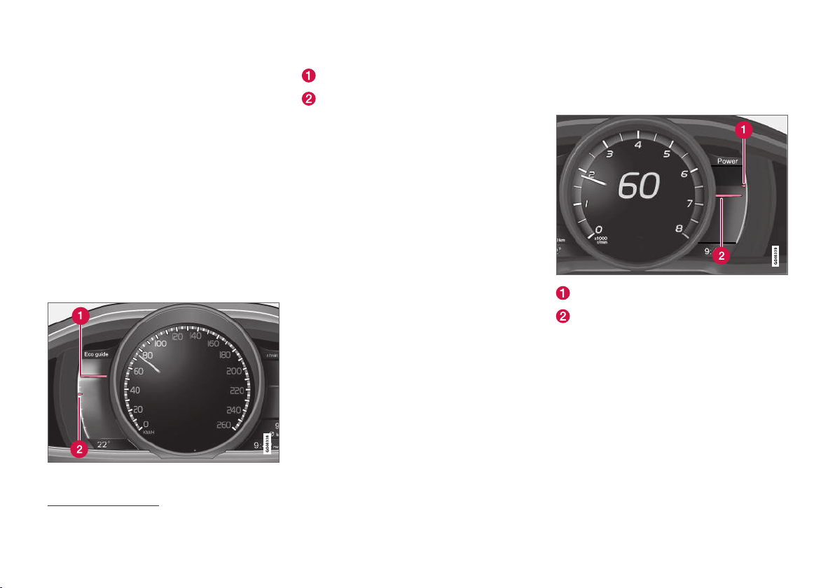
INSTRUMENTS AND CONTROLS
Eco guide & Power guide*
Eco guide and Power guide are two combined
instrument panel (p. 66) instruments which help
the driver to drive the car with optimum driving
economy.
The car also stores statistics of journeys made,
which can be viewed in the form of a block diagram; see Trip computer - trip statistics*
(p. 120).
Eco guide
This instrument provides an indication of how
economically the car is being driven.
To view this function, select the theme "Eco"; see
Digital combined instrument panel - overview
(p. 67).
Instantaneous value
Average value
Instantaneous value
The instantaneous value is shown here - the
higher the reading on the scale, the better.
The instantaneous value is calculated based on
speed, engine speed, engine power utilised plus
use of the foot brake.
Optimum speed (50-80 km/h (30-50 mph)) and
low engine speeds are encouraged. The pointers
fall during acceleration and braking.
Very low instantaneous values illuminate the red
zone on the meter (with a short delay), which
means poor driving economy and hence should
be avoided.
Average value
The average value slowly follows the instantaneous value and describes how the car has been
driven most recently. The higher the pointers on
the scale, the better the economy achieved by
the driver.
Power guide
This instrument shows the relationship between
how much power (Power) is being taken from the
engine and how much power is available.
To view this function, select the theme
"Performance"; see Digital combined instrument
panel - overview (p. 67).
Available engine power
Engine power utilised
Available engine power
The smaller, upper pointer shows the available
engine power9. The higher the reading on the
scale, the more power is available in the current
gear.
Engine power utilised
The larger, lower pointer shows the engine power
utilised9. The higher the reading on the scale, the
more power is being taken from the engine.
A large gap between the two pointers indicates a
large power reserve.
9
Power is dependent on engine speed.
70
* Option/accessory.
Page 73
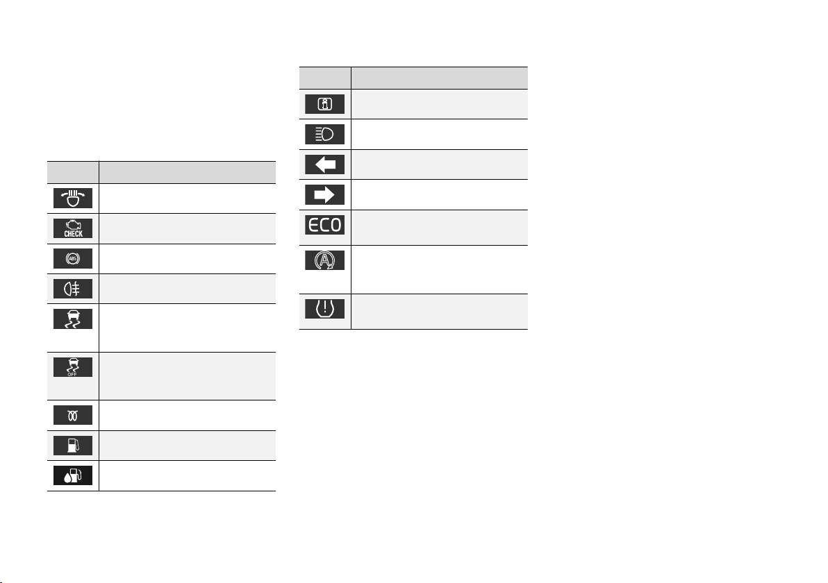
INSTRUMENTS AND CONTROLS
Combined instrument panel meaning of indicator symbols
The indicator symbols alert the driver that a function is activated, that the system is operating, or
that an error or failure has occurred.
Indicator symbols
Symbol Specification
ABL fault
Emissions system
ABS fault
Rear fog lamp on
Stability system, see Electronic stability control (ESC) - general
(p. 184)
Stability system, sport mode, see
Electronic stability control (ESC) operation (p. 186)
Engine preheater (diesel)
Low level in fuel tank
AdBlue system (diesel)
Symbol Specification
Information, read display text
Main beam On
Left-hand direction indicator
Right-hand direction indicator
Eco- function on, see Drive mode
ECO* (p. 285)
Start/Stop, the engine auto-stopped; see Start/Stop* - function and
operation (p. 277)
Tyre pressure system , see Tyre
monitoring (TM)* (p. 326)
ABL fault
The symbol illuminates if a fault has arisen in the
ABL function (Active Bending Lights).
Emissions system
If the symbol illuminates after the engine has
been started then it may be due to a fault in the
car's emissions system. Drive to a workshop for
checking. Volvo recommends that you seek
assistance from an authorised Volvo workshop.
ABS fault
If this symbol illuminates then the system is not
working. The car's regular brake system continues to work, but without the ABS function.
1. Stop the car in a safe place and turn off the
engine.
2. Restart the engine.
3. If the symbol remains illuminated, drive to a
workshop to have the ABS system checked.
Volvo recommends that you seek assistance
from an authorised Volvo workshop.
Rear fog lamp on
This symbol illuminates when the rear fog lamp is
switched on. There is only one rear fog lamp - it
is located on the driver's side.
Stability system
A flashing symbol indicates that the stability system is operating. If the symbol illuminates with
constant glow then there is a fault in the system.
Stability system, sport mode
The symbol illuminates when the sport mode is
activated. Sport mode allows for a more active
driving experience. The system then detects
whether the accelerator pedal, steering wheel
movements and cornering are more active than in
normal driving and then allows controlled skidding of the rear section up to a certain level
before it intervenes and stabilises the car.
* Option/accessory.
}}
71
Page 74
INSTRUMENTS AND CONTROLS
||
Engine preheater (diesel)
This symbol illuminates during engine preheating.
Preheating mostly takes place due to low temperature.
Low level in fuel tank
When the symbol illuminates the level in the fuel
tank is low, refuel as soon as possible.
®10
AdBlue
system (diesel)
This symbol lights up when the AdBlue level is
low or when there is a fault in the AdBlue system.
A message in the display provides information
about the system status.
Information, read display text
When one of the car's systems does not behave
as intended, this information symbol illuminates
and a text appears on the information display.
The message text is cleared with the OK button,
see Menu navigation - combined instrument
panel (p. 110), or it disappears automatically
after a time (time depending on which function is
indicated). The information symbol can also illuminate in conjunction with other symbols.
NOTE
When a service message is shown, the symbol and message are cleared using the OK
button, or disappear automatically after a
time.
Main beam On
The symbol illuminates when main beam is on
and with main beam flash.
Left/right-hand direction indicator
Both direction indicator symbols flash when the
hazard warning flashers are used.
Eco function on
This symbol illuminates when the Eco function is
activated.
Start/Stop
The symbol shines when the engine is auto-stopped.
Tyre pressure system
The symbol illuminates in the event of low tyre
pressure, or if a fault arises in the tyre pressure
system.
Reminder – doors not closed
If one of the doors is not closed properly then the
information or warning symbol illuminates
together with an explanatory image in the information display. Stop the car in a safe place as
soon as possible and close the door that is open.
If the car is driven at a speed lower than
approx. 7 km/h (approx. 4 mph) then the
information symbol illuminates.
If the car is driven at a speed higher than
approx. 7 km/h (approx. 4 mph) then the
warning symbol illuminates.
If the bonnet11 is not closed properly then the
warning symbol illuminates together with an
explanatory image in the information display. Stop
the car in a safe place as soon as possible and
close the bonnet.
If the tailgate is not closed properly then the
information symbol illuminates together with an
explanatory image in the information display. Stop
the car in a safe place as soon as possible and
close the tailgate.
Related information
Combined instrument panel (p. 66)
•
Combined instrument cluster - meaning of
•
warning symbols (p. 73)
Analogue combined instrument panel - over-
•
view (p. 66)
Digital combined instrument panel - overview
•
(p. 67)
10
Registered trademark belonging to Verband der Automobilindustrie e.V. (VDA)
11
Only cars with alarm*.
72
* Option/accessory.
Page 75
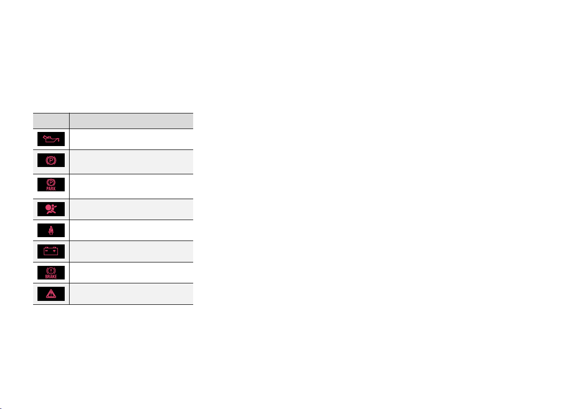
INSTRUMENTS AND CONTROLS
Combined instrument cluster meaning of warning symbols
The warning symbols alert the driver that an
important function is activated, or that a serious
error or a serious failure has occurred.
Warning symbols
Symbol Specification
Low oil pressure
Parking brake applied, digital
instrument panel
Parking brake applied, analogue
instrument panel
Airbags – SRS
Seatbelt reminder
Alternator not charging
Fault in brake system
Warning
A
Certain engine variants do not have systems to warn of oil pressure loss. In cars with these variants the symbol for low oil pressure is not used. Warning for low oil level is via display text. For
more information, see Engine oil - general (p. 342).
A
Low oil pressure
If this symbol illuminates during driving then the
engine's oil pressure is too low. Stop the engine
immediately and check the engine oil level, top
up if necessary. If the symbol illuminates and the
oil level is normal, contact a workshop. Volvo recommends that you seek assistance from an
authorised Volvo workshop.
Parking brake applied
This symbol illuminates with a constant glow
when the parking brake is applied. The symbol is
illuminated during application. For more information, see Parking brake (p. 289).
Airbags – SRS
If the symbol remains illuminated or illuminates
while driving, a fault has been detected in one of
the car's safety systems. Drive to a workshop for
checking as soon as possible. Volvo recommends
that you seek assistance from an authorised
Volvo workshop.
Seatbelt reminder
This symbol flashes if someone in a front seat
has not put on their seatbelt or if someone in a
rear seat has taken off their seatbelt.
Alternator not charging
This symbol illuminates during driving if a fault
has occurred in the electrical system. Visit a
workshop. Volvo recommends that you seek
assistance from an authorised Volvo workshop.
Fault in brake system
If this symbol illuminates, the brake fluid level
may be too low. Stop the car in a safe place and
check the level in the brake fluid reservoir; see
Brake and clutch fluid - level (p. 346).
If the brake and ABS symbols illuminate at the
same time, there may be a fault in the brake
force distribution system.
1. Stop the car in a safe place and turn off the
engine.
2. Restart the engine.
If both symbols extinguish, continue driv-
•
ing.
If the symbols remain illuminated, check
•
the level in the brake fluid reservoir; see
Brake and clutch fluid - level (p. 346). If
the brake fluid level is normal but the
symbols are still illuminated, the car can
be driven, with great care, to a workshop
to have the brake system checked. Volvo
recommends that you seek assistance
from an authorised Volvo workshop.
}}
73
Page 76
INSTRUMENTS AND CONTROLS
||
WARNING
If the brake fluid is below the MIN level in the
brake fluid reservoir, do not drive further
before topping up the brake fluid.
The loss of brake fluid must be investigated
by a workshop. Volvo recommends that you
contact an authorised Volvo workshop.
WARNING
If the BRAKE and ABS symbols are lit at the
same time, there is a risk that the rear end will
skid during heavy braking.
Warning
The red warning symbol illuminates when a fault
has been indicated which could affect the safety
and/or driveability of the car. An explanatory text
is shown on the information display at the same
time. The symbol remains visible until the fault
has been rectified but the text message can be
cleared with the OK button; see Menu navigation
- combined instrument panel (p. 110). The warning symbol can also illuminate in conjunction with
other symbols.
Action:
1. Stop in a safe place. Do not drive the car further.
2. Read the information on the information display. Implement the action in accordance
with the message in the display. Clear the
message using the OK button.
Reminder – doors not closed
If one of the doors is not closed properly then the
information or warning symbol illuminates
together with an explanatory image in the information display. Stop the car in a safe place as
soon as possible and close the door that is open.
If the car is driven at a speed lower than
approx. 7 km/h (approx. 4 mph) then the
information symbol illuminates.
If the car is driven at a speed higher than
approx. 7 km/h (approx. 4 mph) then the
warning symbol illuminates.
If the bonnet12 is not closed properly then the
warning symbol illuminates together with an
explanatory image in the information display. Stop
the car in a safe place as soon as possible and
close the bonnet.
If the tailgate is not closed properly then the
information symbol illuminates together with an
explanatory image in the information display. Stop
the car in a safe place as soon as possible and
close the tailgate.
Related information
Combined instrument panel (p. 66)
•
Combined instrument panel - meaning of
•
indicator symbols (p. 71)
Analogue combined instrument panel - over-
•
view (p. 66)
Digital combined instrument panel - overview
•
(p. 67)
12
74
Only cars with alarm*.
* Option/accessory.
Page 77
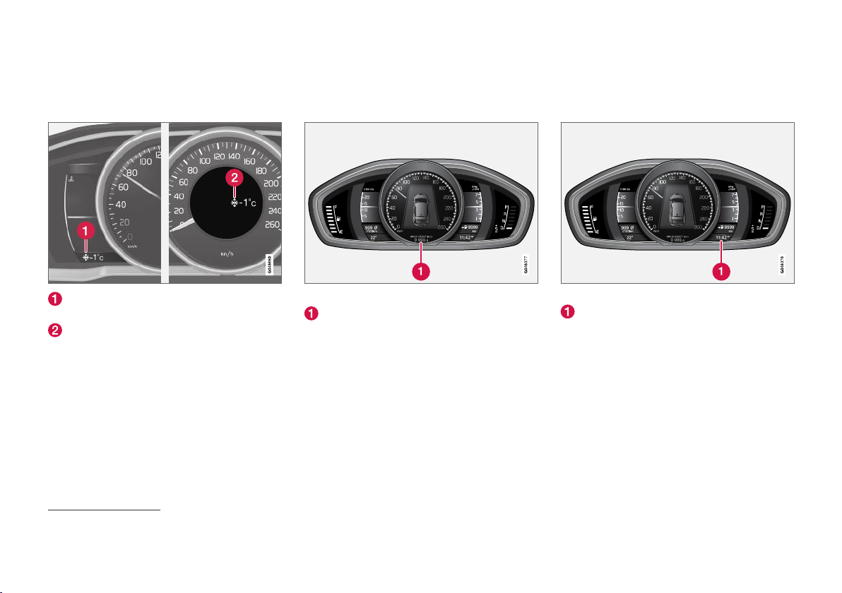
INSTRUMENTS AND CONTROLS
Outside temperature gauge
The display for the outside temperature gauge
appears in the combined instrument panel.
Display for outside temperature gauge, digital instrument panel
Display for outside temperature gauge, analogue instrument panel
When the temperature lies between +2 °C to -5
°C a snowflake symbol illuminates in the display.
This warns of icy roads. If the car has been stationary, the gauge may display a reading that is
too high.
Related information
Combined instrument panel (p. 66)
•
13
Display appearance may differ depending on instrument variant.
Trip meter
The trip meter display appears in the combined
instrument panel.
Trip meter, digital instrument.
Display for trip meter
The two trip meters
measuring short distances. The distance is
shown in the display.
Turn the left stalk switch thumbwheel to show
the required meter.
A long press (until the change occurs) on the
left-hand stalk switch's RESET button resets the
trip meter shown. For more information, see Trip
computer (p. 114).
Related information
Combined instrument panel (p. 66)
•
13
T1 and T2 are used for
Clock
The clock display appears in the combined
instrument panel.
Clock, digital instrument panel.
Display for showing the time
Set the clock
The clock can be adjusted in the menu system
MY CAR, see MY CAR (p. 113).
Related information
Combined instrument panel (p. 66)
•
14
75
Page 78

INSTRUMENTS AND CONTROLS
Combined instrument panel license agreement
A license is an agreement for the right to operate a certain activity or the right to use someone
else's entitlement according to the terms and
conditions in the agreement. The following text is
Volvo's agreement with the manufacturer/developer.
Combined Instrument Panel Software
Open Source Software Notice
This product uses certain free / open source and
other software originating from third parties, that
is subject to the GNU Lesser General Public
License version 2 (LGPLv2), The FreeType
Project License ("FreeType License") and other
different and/or additional copy right licenses,
disclaimers and notices. The links to access the
exact terms of LGPLv2, and the other open
source software licenses, disclaimers,
acknowledgements and notices are provided to
you below. Please refer to the exact terms of the
relevant License, regarding your rights under said
licenses. Volvo Car Corporation (VCC) offers to
provide the source code of said free/open source
software to you for a charge covering the cost of
performing such distribution, such as the cost of
media, shipping and handling, upon written
request. Please contact your nearest Volvo
Dealer.
The offer is valid for a period of at least three (3)
years from the date of the distribution of this
product by VCC / or for as long as VCC offers
spare parts or customer support.
Portions of this product uses software
copyrighted © 2007 The FreeType Project
(www.freetype.org). All rights reserved.
Portions of this product uses software with
Copyright © 1994–2013 Lua.org, PUC-Rio
(http://www.lua.org/)
This product includes software under
following licenses:
LGPL v2.1: http://www.gnu.org/licenses/oldlicenses/lgpl-2.1.html
GNU FriBidi
•
DevIL
•
The FreeType Project License: http://
git.savannah.gnu.org/cgit/freetype/freetype2.git/
tree/docs/FTL.TXT
FreeType 2
•
MIT License: http://opensource.org/licenses/
mit-license.html
Lua
•
14
The time is shown in the middle of the instrument panel when an analogue instrument panel is fitted.
76
Page 79
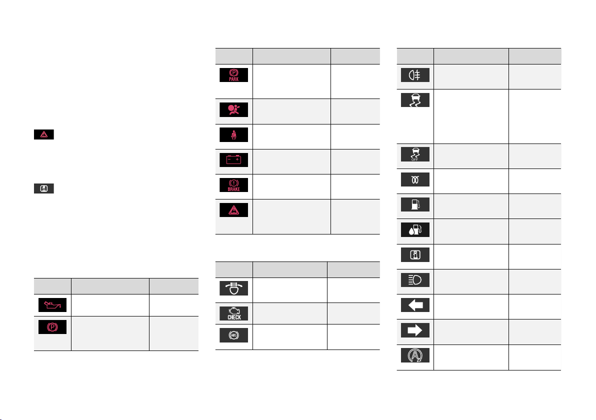
INSTRUMENTS AND CONTROLS
Symbols in the display
There are a variety of different symbols in the
display in the car. The symbols are divided into
warning, indicator and information symbols.
Shown below are the most common symbols with
their meanings and a reference to where in the
manual further information can be found.
- Red warning symbol, illuminates when a
fault has been indicated which could affect the
safety and/or driveability of the car. An explanatory text is shown on the information display in
the combined instrument panel at the same time.
- When one of the car's systems does not
behave as intended, this information symbol illuminates, and a text appears on the information
display in the combined instrument panel. The
yellow information symbol can also illuminate in
conjunction with other symbols.
Warning symbols in the combined instrument panel
Symbol Specification See
Low oil pressure (p. 73)
Parking brake
applied, digital
instrument panel
(p. 73),
(p. 289)
Symbol Specification See
Parking brake
applied, analogue
instrument panel
Airbags – SRS (p. 32),
Seatbelt reminder (p. 28),
Alternator not charging
Fault in brake system
Warning, safety
mode
(p. 73)
(p. 73)
(p. 73)
(p. 73)
(p. 73),
(p. 287)
(p. 32),
(p. 41),
(p. 73)
Control symbols in the combined instrument panel
Symbol Specification See
ABL fault*
Emissions system (p. 71)
ABS fault (p. 71),
(p. 71),
(p. 94)
(p. 287)
Symbol Specification See
Rear fog lamp on (p. 71),
Stability system,
ESC (Electronic
Stability Control),
Trailer stability
assist*
Stability system,
sport mode
Engine preheater
(diesel)
Low level in fuel
tank
AdBlue system
(diesel)
Information, read
display text
Main beam On (p. 71),
Left-hand direction
indicators
Right-hand direction indicators
Start/Stop*, engine
auto-stopped
(p. 98)
(p. 71),
(p. 187),
(p. 309)
(p. 71),
(p. 187)
(p. 71)
(p. 71),
(p. 139)
(p. 300)
(p. 71)
(p. 91)
(p. 71)
(p. 71)
(p. 71),
(p. 277)
}}
* Option/accessory.
77
Page 80
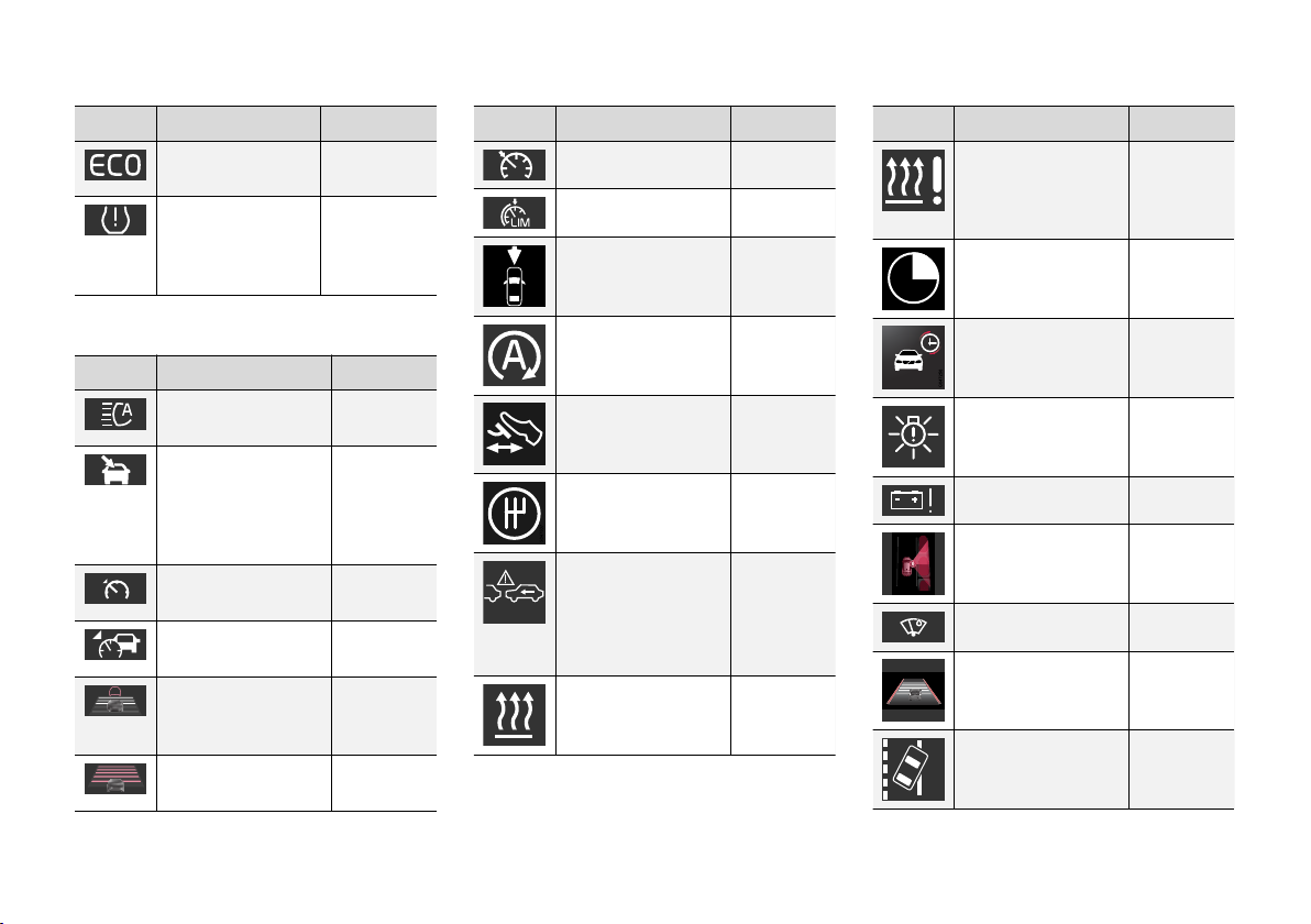
INSTRUMENTS AND CONTROLS
||
Symbol Specification See
ECO function* on
Tyre pressure system*
Information symbols in the combined instrument panel
Symbol Specification See
Main beam with auto
dimming - AHB*
Camera sensor*,
Laser sensor*
Adaptive cruise control*
Adaptive cruise control*
Adaptive cruise control*, Distance Warning* (Distance Alert)
Adaptive cruise control*
(p. 71),
(p. 285)
(p. 71), Tyre
monitoring
(TM)*
(p. 326)
(p. 92)
(p. 92),
(p. 225),
(p. 234),
(p. 247),
(p. 252)
(p. 212)
(p. 204),
(p. 212)
(p. 212),
(p. 197)
(p. 203)
Symbol Specification See
Cruise control*
(p. 192)
Speed limiter (p. 189)
Radar sensor*
(p. 212),
(p. 200),
(p. 234)
Start/Stop*
Start/Stop*
Start/Stop*
Distance warning*
(Distance Alert), City
SafetyTM, Collision
(p. 283)
(p. 283)
(p. 283)
(p. 200),
(p. 225),
(p. 234)
warning system*,
Auto-brake*
Engine block and
(p. 139)
passenger compartment heater*
Symbol Specification See
Engine block heater
(p. 139)
and passenger compartment heater*
Service required
Activated timer*
Activated timer*
ABL system*
(p. 139)
(p. 139)
(p. 94)
Low battery (p. 139)
Park Assist Pilot -
(p. 261)
PAP*
Rain sensor*
Lane assistance*
Driver Alert System*,
(p. 102)
(p. 250)
(p. 252)
Lane assistance*
78
* Option/accessory.
Page 81
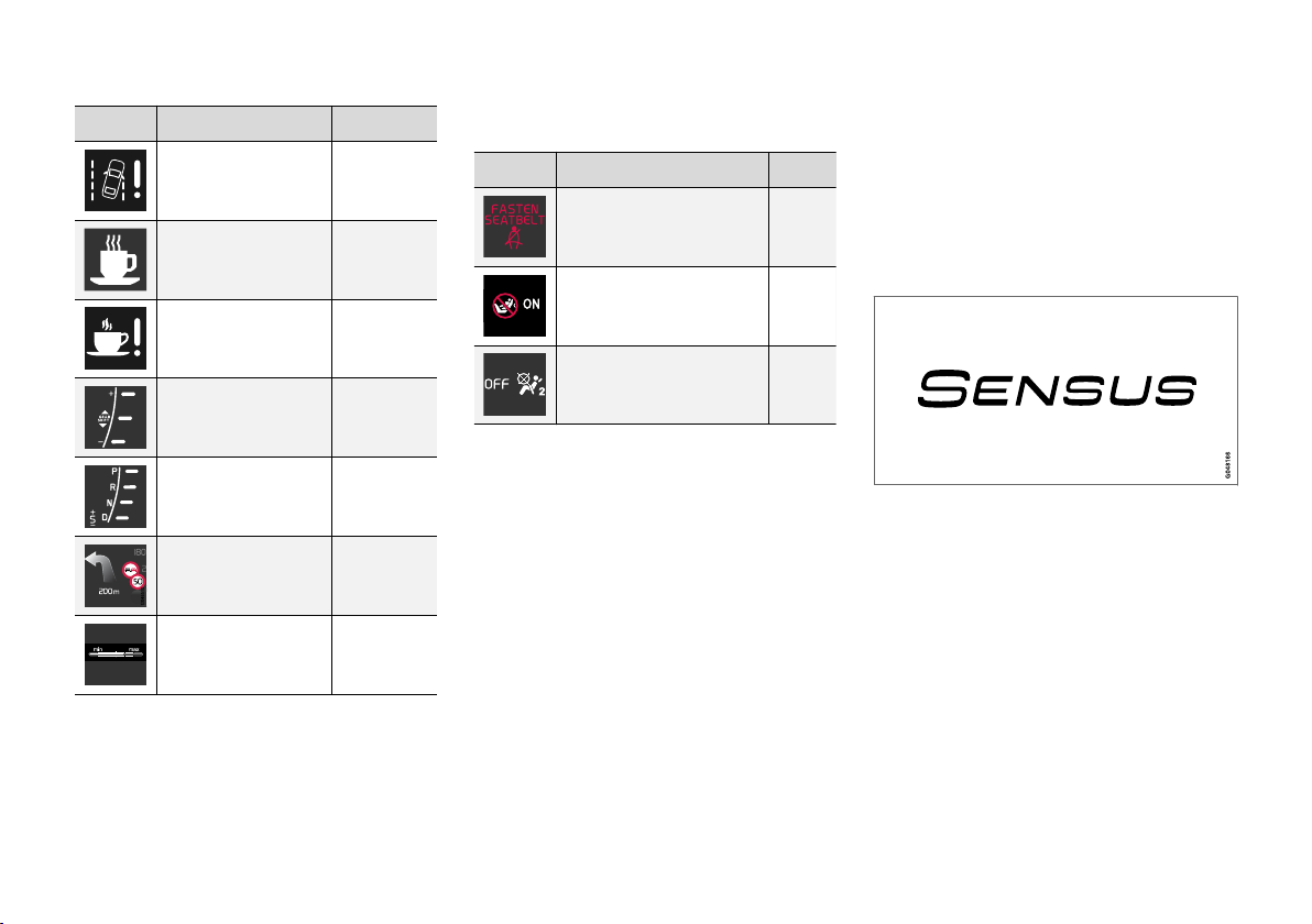
INSTRUMENTS AND CONTROLS
Symbol Specification See
Driver Alert System*,
Lane assistance*
Driver Alert System*,
Time for a break
Driver Alert System*,
Time for a break
Gear shift indicator (p. 272)
Gear positions (p. 272)
Recorded speed
information*
Measuring the oil
level
(p. 247),
(p. 252)
(p. 246)
(p. 247)
(p. 242)
(p. 343)
Information symbols in the roof console display
Symbol Specification See
Seatbelt reminder (p. 31)
Airbag, passenger seat,
activated
Airbag, passenger seat,
deactivated
(p. 36)
(p. 36)
Related information
Combined instrument panel - meaning of
•
indicator symbols (p. 71)
Combined instrument cluster - meaning of
•
warning symbols (p. 73)
Messages - handling (p. 113)
•
Volvo Sensus
Volvo Sensus is the heart of the personal Volvo
experience and connects you with the car and
outside world. Sensus provides information,
entertainment and assistance when it is needed.
Sensus consists of intuitive functions that both
enhance the car journey and simplifies ownership of the car.
An intuitive navigation structure makes it possible
to receive relevant support, information and
entertainment when it is necessary, without distracting the driver.
Sensus covers all the car's solutions that enable
connection* to the outside world and provides
you with intuitive control over all the car's capabilities.
Volvo Sensus combines and presents many functions in several of the car's systems on the centre
console's screen. With Volvo Sensus the car can
be personalised by means of an intuitive user
* Option/accessory.
}}
79
Page 82
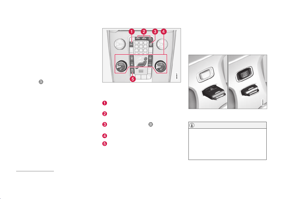
INSTRUMENTS AND CONTROLS
interface. Settings can be made in Car settings,
||
Audio and media, Climate control, etc.
With the centre console buttons and controls or
the steering wheel's right-hand keypad* functions
can be activated or deactivated and many different settings can be made.
With a press on MY CAR all settings related to
the driving and control of the car are presented,
such as City Safety, locks and alarm, automatic
fan speed, setting the clock, etc.
With a press on the respective function RADIO,
MEDIA, TEL*,
*, NAV* and CAM15 other
sources, systems and functions can be activated,
e.g. AM, FM, CD, DVD*, TV*, Bluetooth®*, navigation* and park assist camera*.
For more information about all functions/
systems, see the relevant section in the owner's
manual or its supplement.
Overview
Control panel in centre console. The figure is schematic
- the number of functions and layout of the buttons both
vary, depending on the equipment selected and the market.
Navigation* - NAV, see separate supplement
(Sensus Navigation).
Audio and media - RADIO, MEDIA, TEL*, see
separate supplement (Sensus Infotainment).
Internet-connected car - *, see separate
supplement (Sensus Infotainment).
Climate control system (p. 122).
Function settings - MY CAR, see MY CAR
(p. 113).
Key positions
The remote control key can be used to set the
vehicle's electrical system in different modes/
levels so that different functions are available;
see Key positions - functions at different levels
(p. 81).
Ignition switch with remote control key extracted/
inserted.
NOTE
For cars with the keyless start and lock system* function the key does not need to be
inserted into the ignition switch but can be
stored in e.g. a pocket. For more information
on the keyless start and lock system, see
Keyless drive* (p. 165).
15
Applies to certain car models.
80
* Option/accessory.
Page 83
INSTRUMENTS AND CONTROLS
Insert the key
1. Hold the end of the remote control key with
the detachable key blade and insert the key
in the ignition switch.
2. Then press the key in the lock up to its end
position.
IMPORTANT
Foreign objects in the ignition switch can
impair the function or destroy the lock.
Do not press in the remote control key incorrectly turned - Hold the end with the detachable key blade; see Detachable key blade detaching/attaching (p. 163).
Withdraw the key
Grip the remote control key and pull it out from
the ignition switch.
Key positions - functions at different levels
To enable the use of a limited number of functions with the engine switched off, the car's electrical system can be set in 3 different levels - 0, I
and II - with the remote control key. This owner's
manual describes these levels throughout using
the denomination "key positions".
The following table shows the functions available
in each key position/level.
Level Functions
0
I
II
Odometer, clock and temperature
•
gauge are illuminated.
Electrically operated seats can be
•
adjusted.
The audio system can be used for
•
a limited time - see the Sensus
Infotainment supplement.
Sunroof, power windows, 12 V
•
socket in the passenger compartment, navigation, phone, ventilation
fan and windscreen wipers can be
used.
The headlamps come on.
•
Warning/indicator lamps illuminate
•
for 5 seconds.
Several other systems are acti-
•
vated. However, electric heating in
seat cushions and the rear window
can only be activated after starting
the engine.
This key position consumes a lot of
current from the starter battery and
should therefore be avoided!
}}
81
Page 84
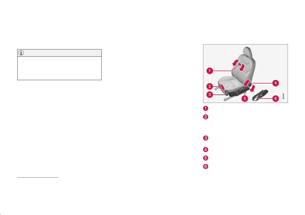
INSTRUMENTS AND CONTROLS
||
Selecting key position/level
Key position 0 - Unlock the car - This
•
means that the car's electrical system is at
level 0.
NOTE
To reach level I or II without starting the
engine - do not depress the brake/clutch
pedal when these key positions are due to be
selected.
Key position I - With the remote control key
•
fully inserted into the ignition switch16 Briefly press START/STOP ENGINE.
Key position II - With the remote control
•
key fully inserted into the ignition switch16 Give a long17 press on START/STOP
ENGINE.
Back to key position 0 - To return to key
•
position 0 from position II and I - Briefly
press on START/STOP ENGINE.
Audio system
For information on audio system functions with
remote control key removed, see the Sensus
Infotainment supplement.
Starting and stopping the engine
For information about starting/switching off the
engine, see Starting the engine (p. 268).
Towing
For important information about the remote control key during towing, see Towing (p. 310).
Related information
Key positions (p. 80)
•
Seats, front
The car's front seats have different setting
options for optimum seating comfort.
To adjust lumbar support*, turn the wheel18.
Forward/backward: lift the handle to adjust
the distance to the steering wheel and pedals. Check that the seat is locked after
adjusting position.
To raise/lower the front edge of seat cushion*, pump up/down.
Adjust backrest rake, turn the wheel.
Raise/lower the seat*, pump up/down.
Control panel for power seat*, see Seats,
front - electrically operated (p. 84).
16
Not required for cars with keyless start and lock system*.
17
Approx. 2 seconds.
18
Also applies to electrically operated seat.
82
* Option/accessory.
Page 85
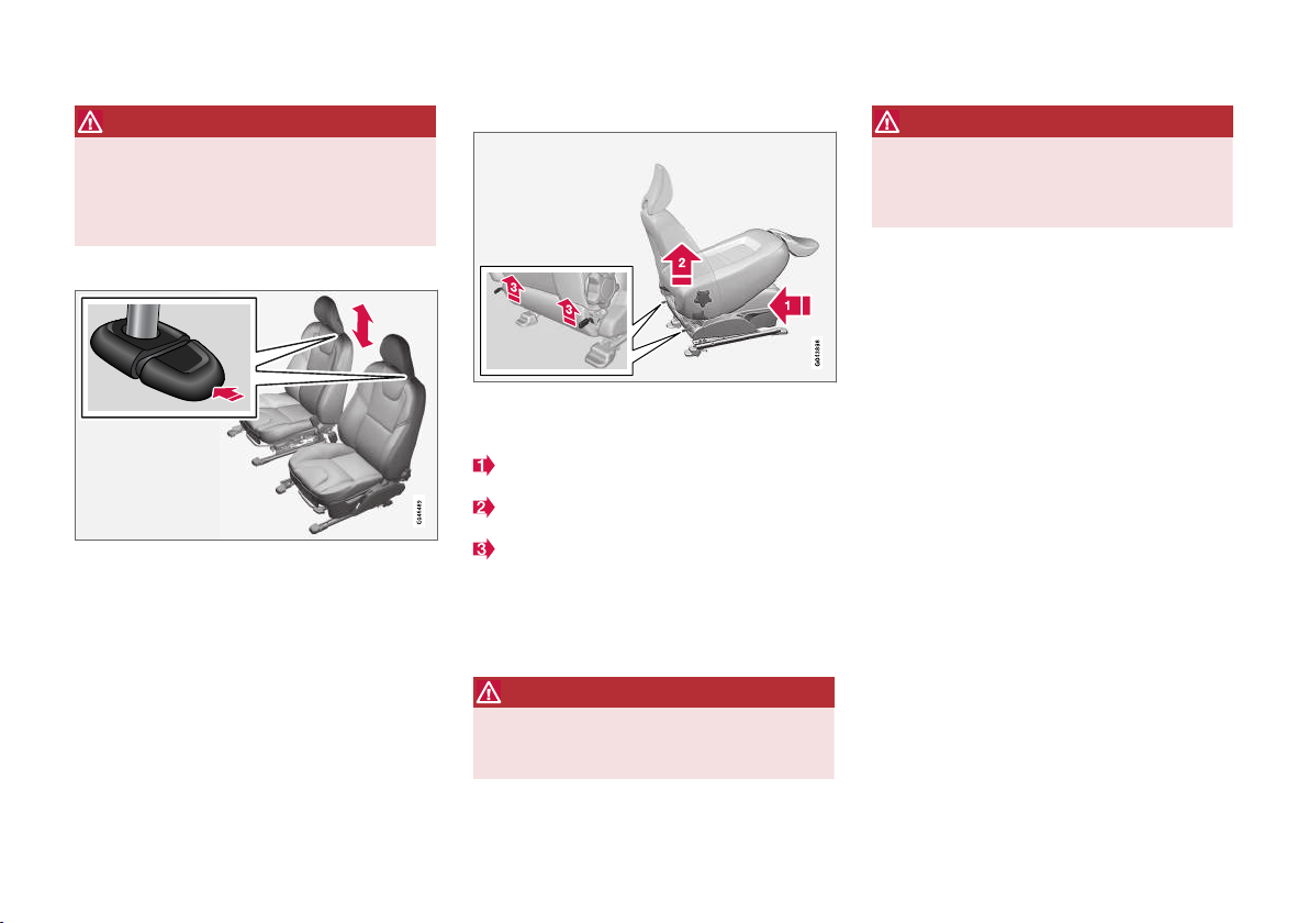
INSTRUMENTS AND CONTROLS
WARNING
Adjust the position of the driver's seat before
setting off, never while driving. Make sure that
the seat is in locked position in order to avoid
personal injury in the event of heavy braking
or an accident.
Adjusting the front seat head restraints
The height of the head restraints can be adjusted.
Adjust the head restraint based on the person's
height so that the whole of the back of the head
is covered if possible.
To adjust the height, the button (see illustration)
must be pressed while the restraint is moved up
or down.
The head restraint can be adjusted in three different positions.
Lowering the passenger seat backrest*
The passenger seat backrest can be folded forward to make room for long loads.
Move the seat as far back/down as possible.
Adjust the backrest to an upright position.
Lift the catches on the rear of the backrest
and fold it forward.
4. Push the seat forward so that the head
restraint "locks" in under the glovebox.
Raising takes place in reverse order.
WARNING
Do not use the seat behind the passenger
seat, or the rear centre seat, when the passenger seat's backrest is lowered.
WARNING
Grasp the backrest and make sure that it is
properly locked after being folded up in order
to avoid personal injury in the event of sudden
braking or an accident.
Related information
Seats, front - electrically operated (p. 84)
•
Seats, rear (p. 85)
•
* Option/accessory.
83
Page 86
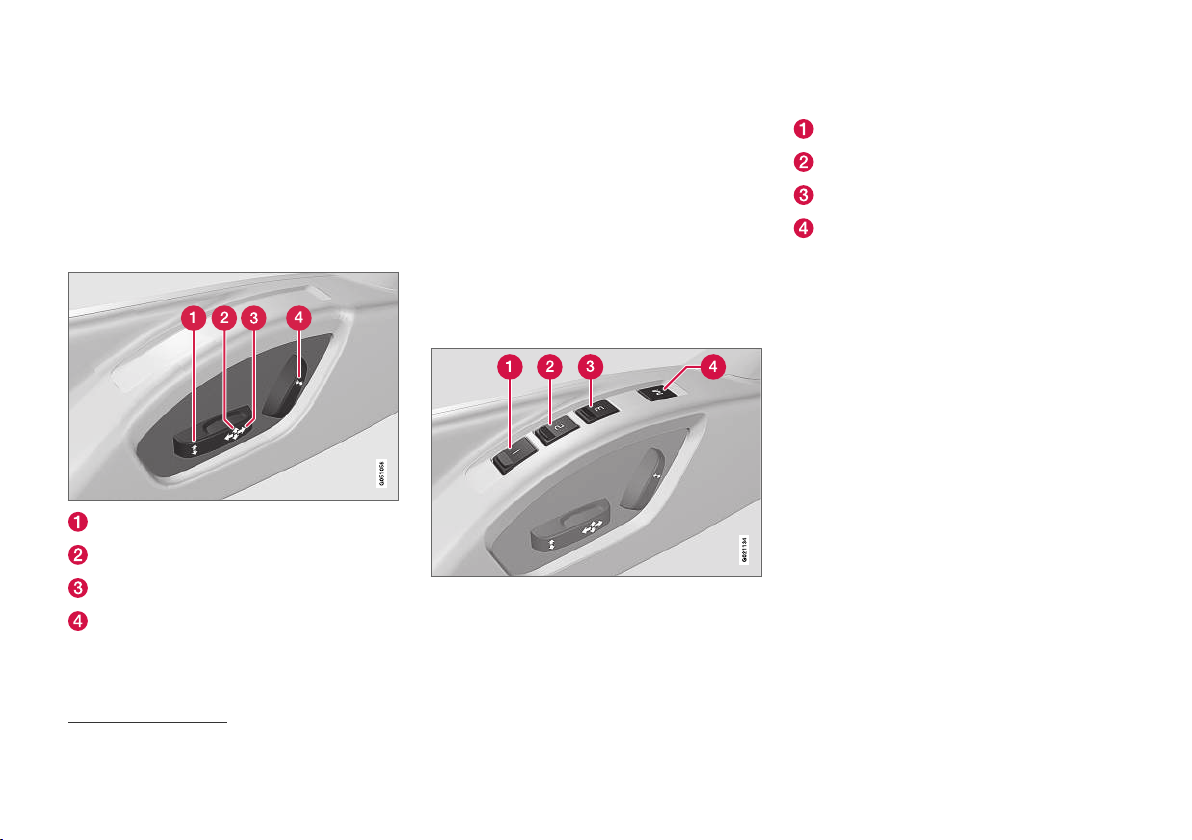
INSTRUMENTS AND CONTROLS
Seats, front - electrically operated
The car's front seats have different setting
options for optimum seating comfort. The power
seat can be moved forward/backward and up/
down. The front edge of the seat cushion can be
raised/lowered. The backrest angle can be
changed.
Electrically operated seat*
Front edge of seat cushion up/down
Raise/lower seat
Seat, forward/backward
Backrest rake
The power seats have overload protection which
is tripped if a seat is blocked by an object. If this
should happen, set the car's electrical system in
key position I or 0 and wait a short time before
adjusting the seat again.
Only one movement (forward/back/up/down)
can be made at a time.
Preparations
The seat can be adjusted for a certain time after
unlocking the door with the remote control key
without the key in the ignition switch. Seat adjustment is normally made in key position I and can
always be made when the engine is running.
Seat with memory function*
The memory function stores settings for the seat
and the door mirrors.
Store setting
Memory button
Memory button
Memory button
Button for storing settings
1. Adjust the seat and the door mirrors.
2.
Press and hold button M while pressing button 1, 2 or 3 simultaneously. Hold the buttons depressed until the acoustic signal is
heard and the text is shown the combined
instrument panel.
The seat must be adjusted again before a new
memory can be set.
Using a stored setting
Press one of the memory buttons 1-3 until the
seat and the door mirrors stop. If the button is
released, the movement of the seat and door mirrors will be interrupted.
Key memory* in remote control key
All remote control keys can be used by different
drivers to store the settings for the driver's seat
and door mirrors19, see Remote control key - personalisation* (p. 157).
19
Only if the car is equipped with power seat with memory and retractable power door mirrors.
84
* Option/accessory.
Page 87
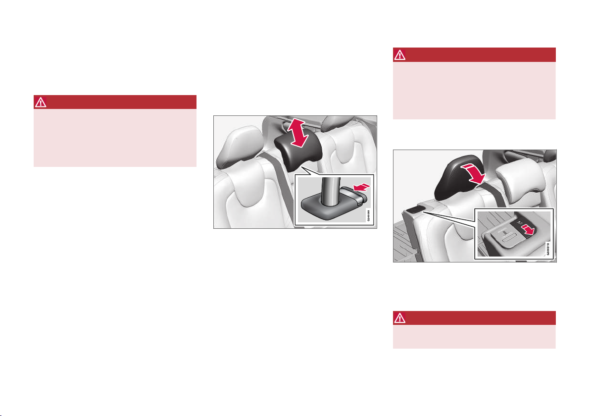
INSTRUMENTS AND CONTROLS
Emergency stop
If the seat accidentally begins to move, press one
of the setting buttons for the seat or memory
buttons in order to stop the seat.
WARNING
Risk of crushing! Make sure that children do
not play with the controls. Check that there
are no objects in front of, behind or under the
seat during adjustment. Make sure that none
of the passengers in the rear seat is in danger
of becoming trapped.
Heated seats
For heated seats, see Heated front seats*
(p. 129) and Heated rear seat* (p. 129).
Related information
Seats, front (p. 82)
•
Seats, rear (p. 85)
•
Seats, rear
The rear seat backrest and the outer seat head
restraints can be folded. The centre seat head
restraint can be adjusted to suit the height of the
passenger.
Head restraint, centre seat, rear
Adjust the head restraint according to passenger
height so that the whole of the back of the head
is covered if possible. Slide it up as required.
To lower the head restraint again, the button (see
illustration) must be pressed while the restraint is
carefully moved down.
The head restraint can be adjusted in five different positions.
WARNING
The centre seat head restraint must be in its
lowest position when the centre seat is not
used. When the centre seat is used, the head
restraint must be correctly adjusted to the
height of the passenger so that it covers the
whole of the back of the head if possible.
Manual lowering of the outer head restraints, rear seat
Pull the locking handle closest to the head
restraint to fold the head restraint forward.
The head restraint is moved back manually.
WARNING
The head restraint must be in locked position
after being folded up.
* Option/accessory.
}}
85
Page 88
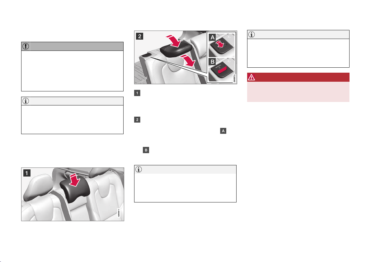
INSTRUMENTS AND CONTROLS
||
Lowering the rear seat backrest
IMPORTANT
When the backrest is to be folded, the rear
seat cup holder must not be open and there
must be no objects in the rear seat. Nor may
the seat belts be connected. Otherwise there
is a risk of damage to the rear seat upholstery.
NOTE
The front seats may need to be pushed forwards, and/or the backrests adjusted
upwards, in order that the rear backrests can
be fully folded forward.
Both sections can be folded separately.
•
If the entire backrest is to be folded then the
•
different sections should be folded separately.
If the right-hand section is being lowered release and adjust head restraint for the centre seat, see the earlier section "Head
restraint, centre seat, rear".
The outer head restraints are lowered automatically when the backrests are lowered.
Pull up the backrest's locking handle
while folding the backrest forward at the
same time. A red indicator on the lock catch
shows that the backrest is no longer
locked in place.
NOTE
When the backrests have been lowered the
head restraints must be moved forward
slightly so as not to make contact with the
seat cushion.
NOTE
When the backrest has been raised, the red
indicator should no longer be showing. If it is
still showing then the backrest is not locked
in place.
WARNING
Check that the backrests and head restraints
in the rear seat are locked properly after
being folded up.
Related information
Seats, front (p. 82)
•
Seats, front - electrically operated (p. 84)
•
86
Raising takes place in reverse order.
Page 89
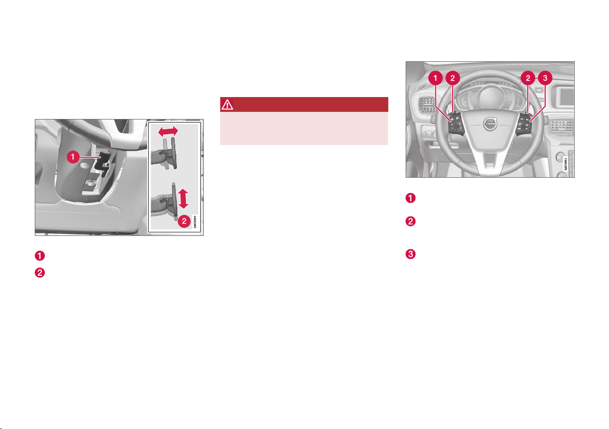
INSTRUMENTS AND CONTROLS
Steering wheel
The steering wheel can be adjusted in different
positions and has controls for horn and cruise
control, as well as menu, audio and phone control.
Adjusting
Adjusting the steering wheel.
Lever - releasing the steering wheel
Possible steering wheel positions
The steering wheel can be adjusted for both
height and depth:
1. Push the lever forwards to release the steering wheel.
2. Adjust the steering wheel to the position that
suits you.
3. Pull the lever back to fix the steering wheel
in place. If the lever is stiff, press the steering
wheel lightly at the same time as you push
the lever back.
WARNING
Adjust the steering wheel and fix it before
driving away. The steering wheel must never
be adjusted while driving.
With speed related power steering* the level of
steering force can be adjusted, see Adjustable
steering force* (p. 184).
Keypads* and paddles*
Keypads and paddles in the steering wheel.
Cruise control* (p. 192) and Adaptive cruise
control (ACC)* (p. 201).
Paddle for manual gear changing in an automatic gearbox, see Automatic gearbox Geartronic* (p. 272).
Audio and phone control, see supplement
Sensus Infotainment.
* Option/accessory.
}}
87
Page 90
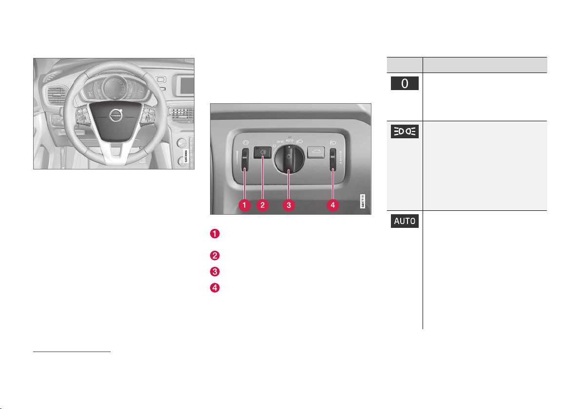
INSTRUMENTS AND CONTROLS
||
Horn
Horn.
Press the centre of the steering wheel to signal.
Light switches
The headlamp control activates and adjusts the
external lighting. It is also used to adjust display
and instrument lighting and ambience lights
(p. 100).
Overview, light switches.
Thumbwheel for adjusting display and instrument lighting as well as ambience lights*
Button for rear fog lamp
Knob for lighting while driving and parking
Thumbwheel for headlamp levelling
A car with LED20 headlamps* has automatic
headlamp levelling and therefore does not have
the thumbwheel for headlamp levelling.
Knob positions
Position Specification
Daytime running lightsA when the
car's electrical system is in key
position II or the engine is running.
Main beam flash can be used.
Daytime running lights, side marker
lamps rear and position lamps
when the car's electrical system is
in key position II or the engine is
running.
Side marker lamps rear and position lamps when the car is parkedB.
Main beam flash can be used.
Daytime running lights, side marker
lamps rear and position lamps in
daylight when the car's electrical
system is in key position II or the
engine is running.
Dipped beam, side marker lamps
rear and position lamps in weak
daylight or darkness, or when rear
fog lamps are activated.
The tunnel detection (p. 91)*
function is activated.
20
LED (Light Emitting Diode)
88
* Option/accessory.
Page 91
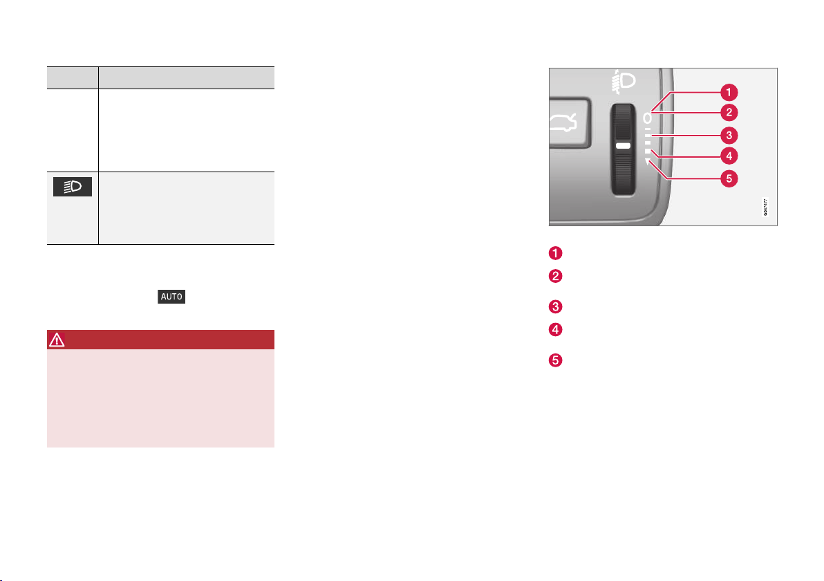
INSTRUMENTS AND CONTROLS
Position Specification
The Active main beam (p. 92)*
function can be used.
Main beam can be activated when
dipped beam is switched on.
Main beam flash can be used.
Dipped beam, side marker lamps
rear and position lamps.
Main beam can be activated.
Main beam flash can be used.
A
Fitted in or under the front bumper.
B
Also at idle when the engine is running, provided that the knob
is moved to this position from another position.
Volvo recommends that mode is used
when the car is driven.
WARNING
The car's audio system is not able to determine when daylight is too weak or sufficiently
strong, e.g. in fog and rain, in all situations.
The driver is always responsible for ensuring
that the car is driven with a beam pattern suitable for the traffic situation and in accordance
with applicable traffic regulations.
Display and instrument lighting
Different display and instrument lighting is
switched on depending on key position; see Key
positions - functions at different levels (p. 81).
The display lighting is automatically subdued in
darkness - the sensitivity is set with the thumbwheel.
The intensity of the instrument lighting is
adjusted with the thumbwheel.
Headlamp levelling
The load in the car changes the vertical alignment of the headlamp beam, which could dazzle
oncoming motorists. Avoid this by adjusting the
height of the beam. Lower the beam if the car is
heavily laden.
1. Leave the engine running, or have the car's
electrical system in key position I.
2. Roll the thumbwheel up/down to raise/lower
beam alignment.
Thumbwheel positions for different load cases.
Only driver
Driver and passenger in the front passenger
seat
Occupants in all seats
Occupants in all seats and maximum load in
the cargo area
Driver and maximum load in the cargo area
Related information
Position lamps (p. 90)
•
Daytime running lights (p. 90)
•
Main/dipped beam (p. 91)
•
* Option/accessory.
89
Page 92
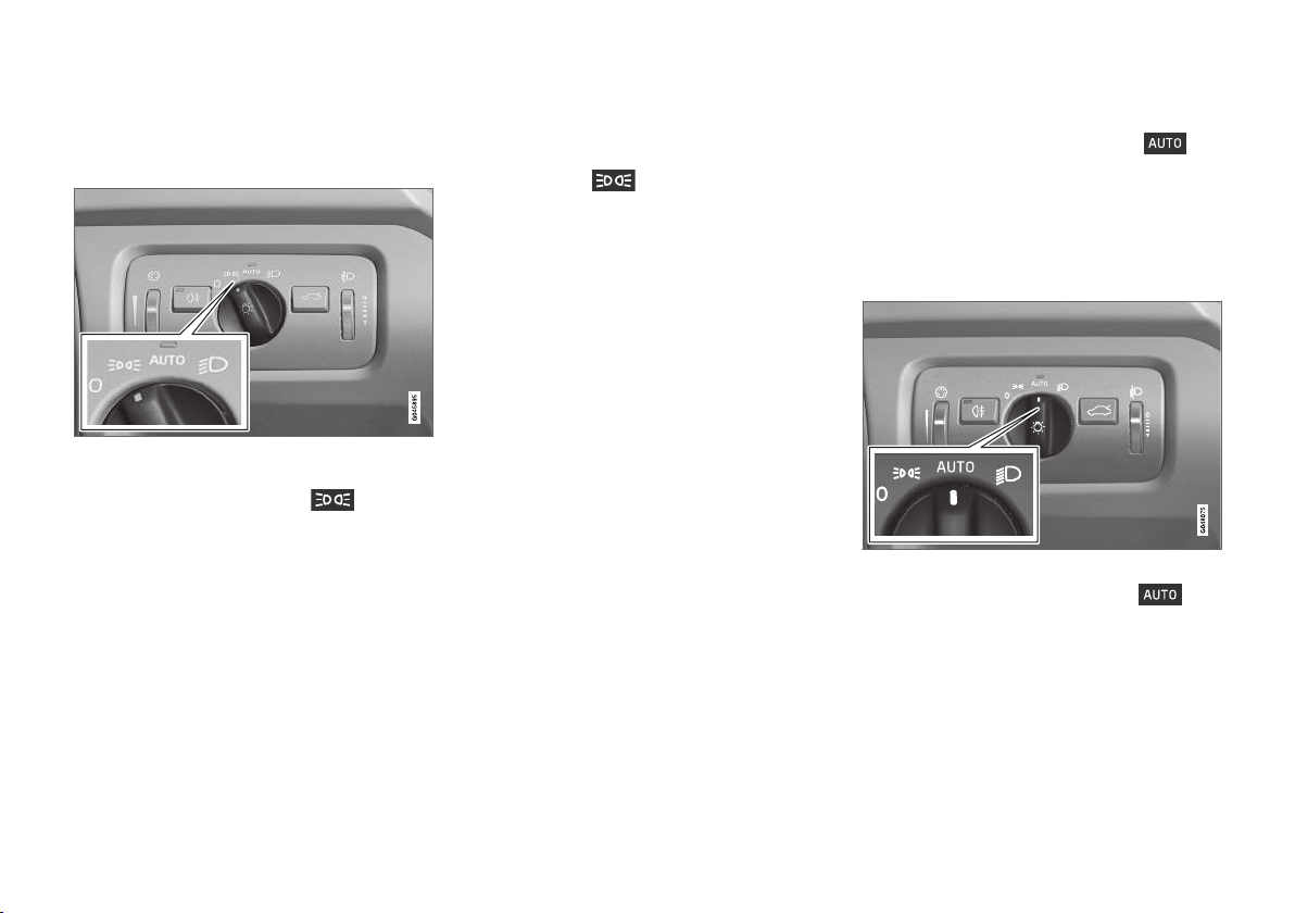
INSTRUMENTS AND CONTROLS
Position lamps
Position lamps are switched on using the headlamp control's knob.
Knob for headlamp control in the position for position
lamps.
Turn the knob to the position for (number
plate lighting is switched on at the same time).
If the car's electrical system is in key position II or
the engine is running then the daytime running
lights also switch on.
When it is dark outside and the tailgate is
opened the rear position lamps illuminate to alert
traffic behind. This takes place irrespective of
what position the knob is in or what key position
the car's electrical system is in.
When driving for more than 30 seconds at max.
10 km/h (approx. 6 mph), or if the speed
exceeds 10 km/h (approx. 6 mph), the daytime
running lights are switched on and Reset light
switch position is shown in the combined
instrument panel, which prompts you to turn to a
mode other than
.
Related information
Light switches (p. 88)
•
Daytime running lights
With the knob for headlamp control in
position, and the car's electrical system in key
position II or the engine running, the daytime
running lights are activated automatically in daylight.
Daytime running lights during the day. DRL
Knob for headlamp control in AUTO position.
With the knob for headlamp control in
position the daytime running lights (Daytime
Running Lights - DRL) are activated automatically when the car is driven in daylight. A light
sensor on the top of the instrument panel
changes from daytime running lights to dipped
beam at twilight or when daylight becomes too
weak. Switching to dipped beam also takes place
when the rear fog lamps are activated.
90
Page 93
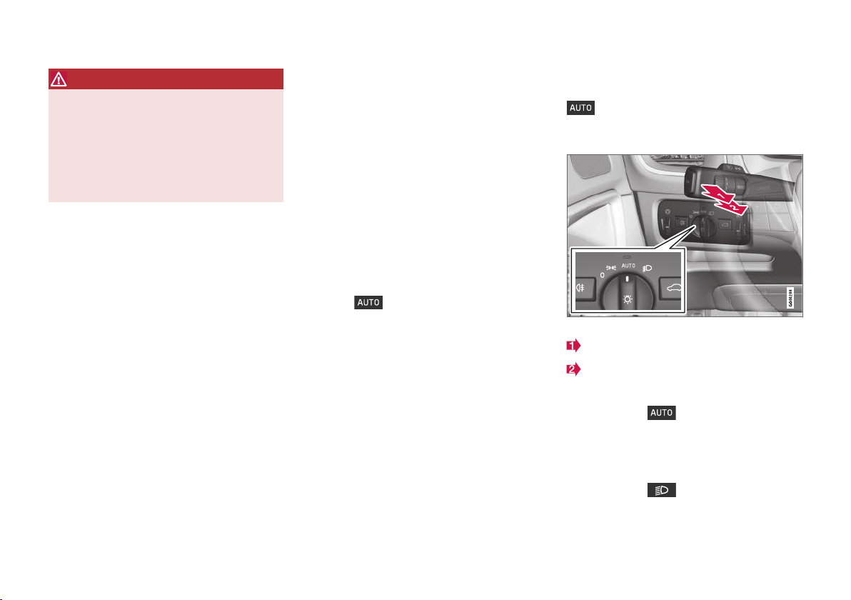
INSTRUMENTS AND CONTROLS
WARNING
This system help to save energy - it cannot
determine in all situations when daylight is too
weak or sufficiently strong, e.g. in mist and
rain.
The driver is always responsible for ensuring
that the car is driven with the correct beam
pattern for the traffic situation and in accordance with applicable traffic regulations.
Related information
Main/dipped beam (p. 91)
•
Light switches (p. 88)
•
Tunnel detection*
Tunnel detection changes the lighting from daytime running lights to dipped beam when the car
is driven into a tunnel.
The tunnel detection function is available in cars
with rain sensor*. The sensor detects the
entrance to a tunnel and resets the lighting from
daytime running lights to dipped beam. Approx.
20 seconds after the car has left the tunnel, the
lighting returns to daytime running lights. If the
car is driven into another tunnel within this time
period then dipped beam is kept switched on.
This prevents frequent changes to the car's beam
pattern.
Note that the headlamp control's knob must
remain in
work.
Related information
Main/dipped beam (p. 91)
•
Light switches (p. 88)
•
position for tunnel detection to
Main/dipped beam
With the knob for headlamp control in position
and the car's electrical system in key posi-
tion II or the engine running, the dipped beam is
activated automatically in poor light conditions.
Stalk switch and knob for headlamp control.
Position for main beam flash
Position for main beam
Dipped beam
With the knob in position, dipped beam is
activated automatically at dusk or when daylight
becomes too weak. Dipped beam is also activated automatically if the rear fog lamp is activated.
With the knob in
always switched on when the engine is running
or when key position II is active.
position, dipped beam is
}}
* Option/accessory.
91
Page 94
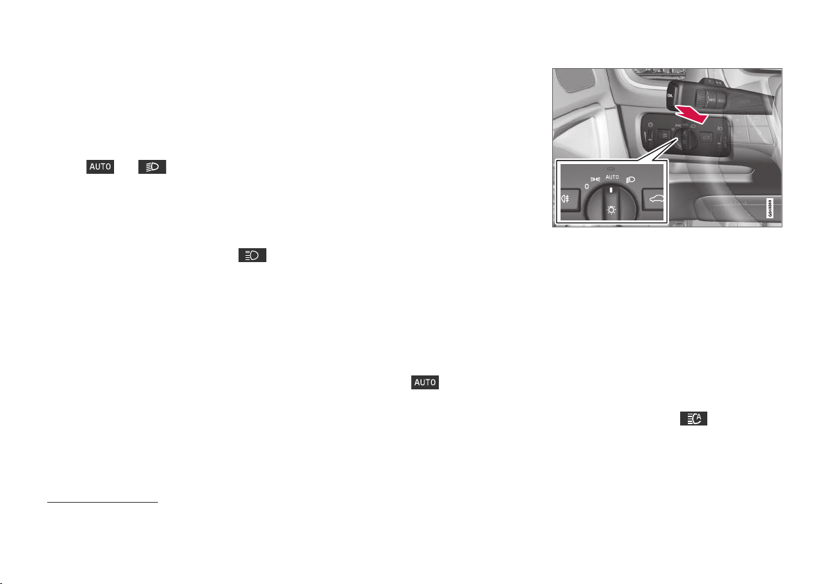
INSTRUMENTS AND CONTROLS
||
Main beam flash
Move the stalk switch gently towards the steering
wheel to the position for main beam flash. Main
beam comes on until the stalk switch is released.
Main beam
Main beam can be activated when the knob is in
position
main beam by moving the stalk switch towards
the steering wheel to the end position and then
releasing. Alternatively, the main beam can be
deactivated by a light press of the stalk switch
toward the steering wheel.
When main beam has been activated the
symbol illuminates in the combined instrument
panel.
21
or
. Activate/deactivate
Related information
Active bending lights* (p. 94)
•
Active main beam* (p. 92)
•
Light switches (p. 88)
•
Headlamps - adjusting headlamp pattern
•
(p. 95)
Tunnel detection* (p. 91)
•
Active main beam*
Active main beam function detects the headlamp
beams from oncoming traffic or the rear lights of
vehicles in front, and switches the lighting from
main beam to dipped beam. The lighting returns
to main beam when the incoming light has stopped.
Active main beam - AHB
Active main beam (Active High Beam - AHB) is a
function which uses a camera sensor at the top
edge of the windscreen to detect the headlamp
beams from oncoming traffic or the rear lights of
vehicles in front, and then switches from main
beam to dipped beam. The function can also take
streetlights into account.
The lighting returns to main beam about a second after the camera sensor no longer detects
the headlamp beams from oncoming traffic or the
rear lights from vehicles in front.
Activating/deactivating
AHB can be activated when the headlamp control's knob is in position
function has not been deactivated in the menu
system MY CAR, see MY CAR (p. 113)).
(provided that the
Stalk switch and knob for headlamp control in AUTO
position.
The function can start while driving in the dark
when the car's speed is approx. 20 km/h
(12 mph) or higher.
Activate/deactivate AHB by moving the left-hand
stalk switch towards the steering wheel to the
end position and then releasing. Deactivation
when main beam is on means that the lights are
reset directly to dipped beam.
Car with analogue combined instrument
panel
When AHB is activated the symbol illuminates in the instrument's information display.
21
When dipped beam is activated.
92
* Option/accessory.
Page 95
INSTRUMENTS AND CONTROLS
When main beam has been switched on the
symbol also illuminates in the combined
instrument panel.
Car with digital combined instrument panel
When AHB is activated the
white in the instrument's information display.
When main beam is activated, the symbol shines
blue.
Manual operation
symbol turns
NOTE
Keep the windscreen surface in front of the
camera sensor free from ice, snow, mist and
dirt.
Do not stick or attach anything to the windscreen in front of the camera sensor as this
may reduce effectiveness or cause one or
more of the systems dependent on the camera to stop working.
If the message Active main beam Temporary
unavailable Switch manually is shown in the
combined instrument panel's information display
then you have to switch manually between main
and dipped beam. However, the knob for head-
lamp control can still remain in position
The same applies if the message
sensors blocked See manual and the
Windscreen
.
symbol are shown. The symbol goes out
when these messages are shown.
AHB may be temporarily unavailable e.g. in situations with dense fog or heavy rain. When AHB
becomes available again, or the windscreen sensors are no longer blocked, the message goes
out and the
symbol illuminates.
WARNING
AHB is an aid for using the optimum beam
pattern when conditions are favourable.
The driver always bears responsibility for manually switching between main and dipped
beam when traffic situations or weather conditions so require.
IMPORTANT
Examples of when manual switching between
main and dipped beam may be required:
In heavy rain or dense fog
•
In freezing rain
•
In snow flurries or slush
•
In moonlight
•
When driving in poorly lit built-up areas
•
When the traffic ahead has weak lighting
•
If there are pedestrians on or beside the
•
road
If there are highly reflective objects such
•
as signs in the vicinity of the road
When the lighting from oncoming traffic
•
is obscured by e.g. a crash barrier
When there is traffic on connecting roads
•
On the brow of a hill or in a hollow
•
In sharp bends.
•
For more information on the limitations of the
camera sensor, see Collision warning system* camera sensor limitations (p. 233).
Related information
Main/dipped beam (p. 91)
•
Light switches (p. 88)
•
* Option/accessory.
93
Page 96
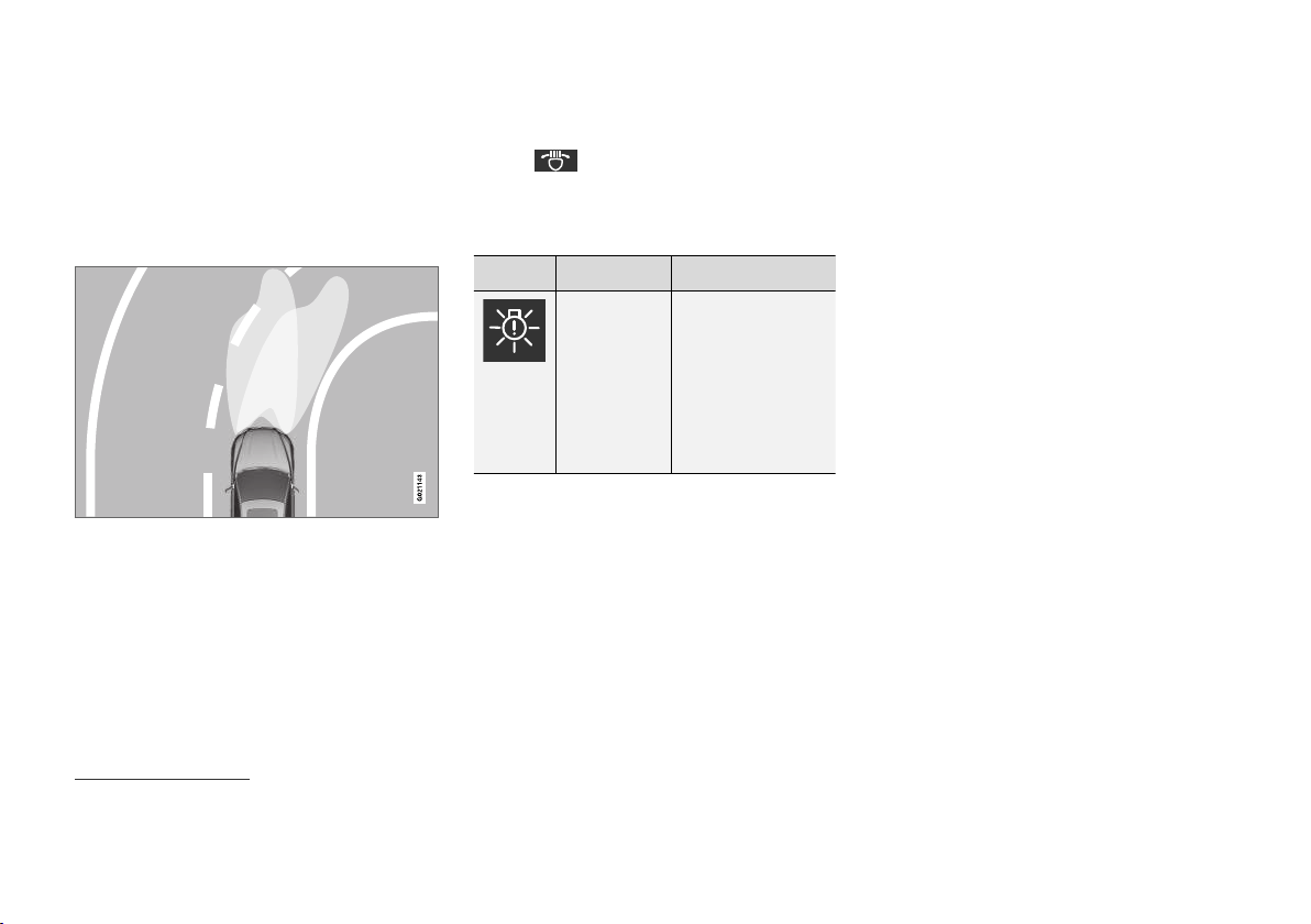
INSTRUMENTS AND CONTROLS
Active bending lights*
Active bending lights are designed to provide
maximum illumination in bends and junctions.
Cars with LED22 headlamps* can have active
bending lights, depending on the car's equipment level.
Headlamp pattern with function deactivated (left) and
activated (right) respectively.
The LED headlamps can include the Active bending lights function, depending on the car's equipment level. Active bending lights follow steering
wheel movements to provide maximum illumination in bends and junctions and thereby increase
safety.
The function is activated automatically when the
car is started (provided that it has not been deac-
tivated in the menu system MY CAR, see MY
CAR (p. 113)). In the event of a fault in the func-
tion the
symbol illuminates in the combined instrument panel at the same time as the
information display shows an explanatory text and
a further illuminated symbol.
Symbol Message Specification
Headlamp
system
malfunction
Service
required
The system is disengaged. Visit a
workshop if the
message remains.
Volvo recommends
that you contact an
authorised Volvo
workshop.
The function is only active in twilight or darkness
and only when the car is moving.
The function23 can be deactivated/activated in
the menu system MY CAR, see MY CAR
(p. 113).
Related information
Main/dipped beam (p. 91)
•
Active main beam* (p. 92)
•
Light switches (p. 88)
•
22
LED (Light Emitting Diode)
23
Activated on delivery from the factory.
94
* Option/accessory.
Page 97

INSTRUMENTS AND CONTROLS
Headlamps - adjusting headlamp pattern
The halogen headlamp pattern must be adjusted
to avoid dazzling oncoming motorists and can
be set for right or left-hand traffic.
LED headlamps*
The light pattern does not need to be adjusted.
The headlamp pattern is designed in such a way
that oncoming traffic is not dazzled.
Halogen headlamps
The headlamp pattern for halogen headlamps is
readjusted by masking the headlamp lens. The
headlamp pattern may not be as good.
Masking the headlamps
1. Copy the A and B templates for left-hand
drive cars or the C and D templates for righthand drive cars, see later section "Templates
for halogen headlamps". The templates have
a scale of 1:2. Use a photocopier with a
zoom function for example, and copy the
templates at 200 %:
A = LHD Right (left-hand drive, right lens)
•
B = LHD Left (left-hand drive, left lens)
•
C = RHD Right (right-hand drive, right
•
lens)
D = RHD Left (right-hand drive, left lens)
•
2. Transfer the template to a self-adhesive
waterproof material and cut it out.
3. Start from the design lines on the headlamp
lenses; see the lines in the following figure.
Position the self-adhesive templates at the
design lines with the help of the illustration.
* Option/accessory.
}}
95
Page 98
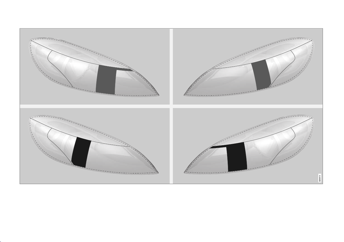
INSTRUMENTS AND CONTROLS
||
Upper row: left-hand drive cars, templates A and B. Lower row: right-hand drive cars, templates C and D.
96
Page 99
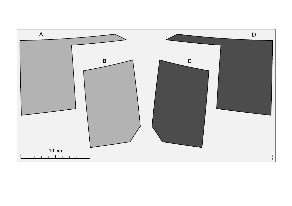
Templates for halogen headlamps
INSTRUMENTS AND CONTROLS
97
Page 100
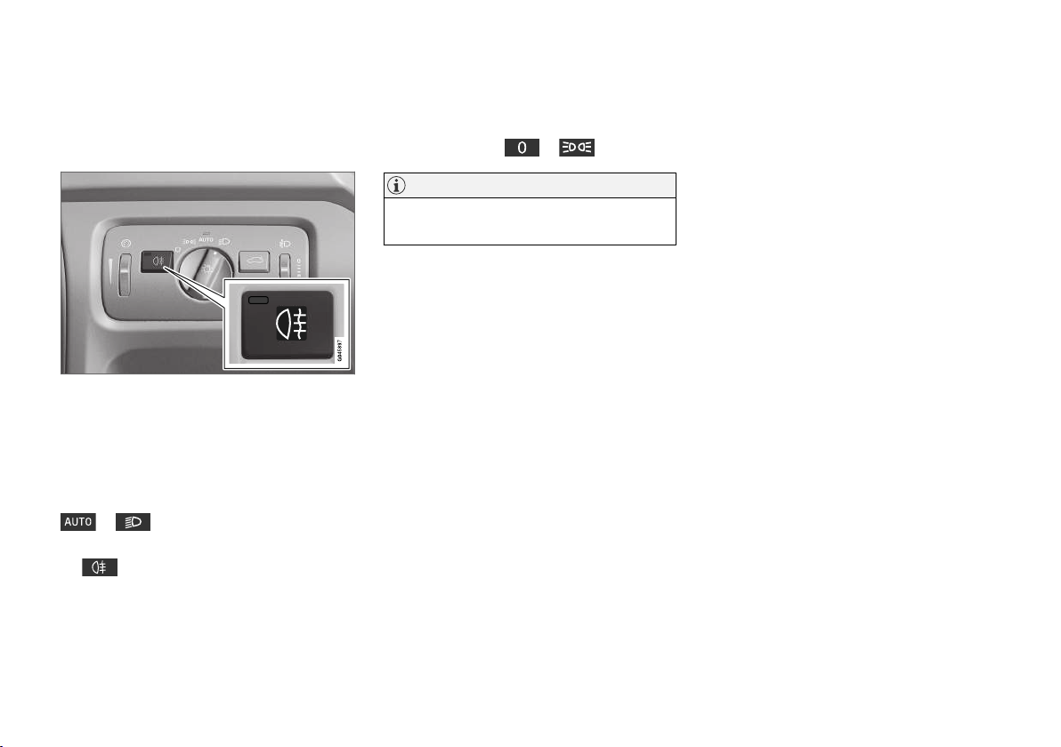
INSTRUMENTS AND CONTROLS
Rear fog lamp
When visibility is reduced by fog the rear fog
lamp can be used so that other road users can
detect the vehicle in front at an early stage.
Button for rear fog lamp.
The rear fog lamp consists of a lamp on the lefthand side in a left-hand drive car, or on the righthand side in a right-hand drive car.
The rear fog lamp can only be switched on when
key position II is active or the engine is running
and the headlamp control's knob is in position
or .
Press the button for On/Off. The indicator symbol
the light in the button both illuminate when the
rear fog lamp is switched on.
in the combined instrument panel and
The rear fog lamp is switched off automatically
when the START/STOP ENGINE button is
depressed or when the headlamp control's knob
is turned to position
or .
NOTE
Regulations on the use of rear fog lamps vary
from country to country.
Related information
Light switches (p. 88)
•
Brake lights
The brake light automatically comes on during
braking.
The brake light is switched on when the brake
pedal is depressed. In addition, it is switched on
when one of driving support systems Adaptive
cruise control (p. 201), City Safety (p. 219) or
Collision warning system (p. 226) brakes the car.
Related information
Foot brake - emergency brake lights and
•
automatic hazard warning flashers (p. 288)
98
 Loading...