

Publ. No. 3061
Dec. 1975
WORKSHOP MANUAL
MD5A
Marine diesel engine
ENGINE UNIT

FOREWORD
This workshop manual contains repair instructions for the MD5A marine diesel engine. The instructions
concerning overhauling describe the most suitable working method to be used with the special tools listed under
the heading “Special tools”.
Both the engine designation and its serial number must be clearly stated in all correspondence concerning the
engine and when ordering spare parts. We reserve the right to carry out design modifications and, for this
reason, the contents of this manual cannot he regarded as binding.
AB VOLVO PENTA
Technical Information Department
NEW UNITS OF MEASUREMENT
Technicians have long since tried to establish an internationally standardized system of
measurements. In 1960 a decision was made to use a system called SI (Systéme International
d’Unites). To a large extent, this system is based on earlier systems but the units have been
made uniform so that no conversions are necessary.
The SI-system is now being applied within industry in Europe, This manual contains the new SIunits. The units used previously however, are also stated but in brackets.
The new units are:
Output is slated in kW (kilowat ts)
earlier unit h.p. (horsepower)
Torque is stated in NM (Newton-metres)
earlier unit kpm (kilopond-metres)
Engine speed is stated in r/s (revolutions per second)
earlier unit r.p.m. (revolutions per minute)
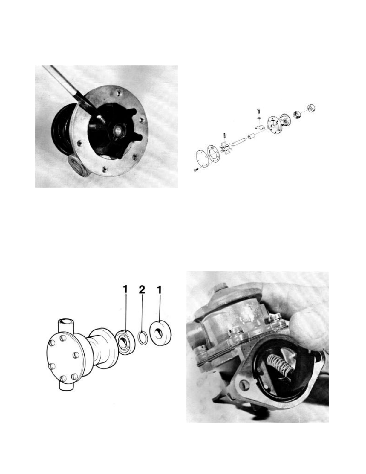
Displacement and volumes are stated in dm
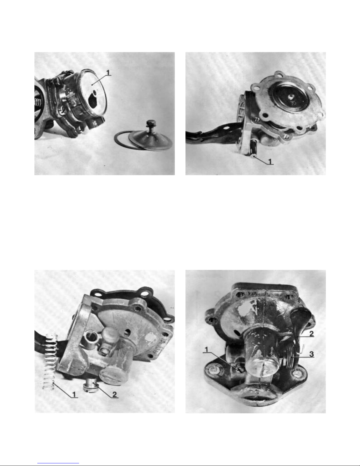
earlier unit l (litres)
Pressure is stated in Pa (Pascal)
earlier unit kp/cm2 (kiloponds per square centimetre).
Reproduction permitted if source quoted
3 (
cubic decimetres)

CONTENTS
Presentation 2
Dismantling
Electrical system, thermostat housing cylinder head 3
Flywheel, fuel injector pump 4
Oil pump, transmission cover, governor 5
Lubricating oil pump, camshaft, cylinder 6
Crankshaft, cylinder liner, camshaft bearing 7
Overhauling
Lubricating oil pump, sea -water pump 7 – 9
Feed pump 9 – 11
Fuel filter, crankshaft 11
Centrifugal governor, piston 12 – 13
Valve guides, nozzle sleeve 14 – 15
Valves, valve seats, rocker mechanism, injector 15 – 16
Hand start mechanism, camshaft 17
Assembling
Cylinder liner, crankshaft 18
Cylinder, camshaft, governor 19
Lubricating oil pump, transmission cover 20
Adjustment of control rod travel, assembling
flywheel cover 20 – 21
Oil sump, cylinder head, feed cover 22
Fuel filter, injector, thermostat 22
Flywheel, generator, valve adjus tment 24
Checking injection angle 25
Bleeding the fuel system, electrical system 26
Wiring diagram 27
Fault-tracing system 28
Special tools 29
Technical data 30 – 33
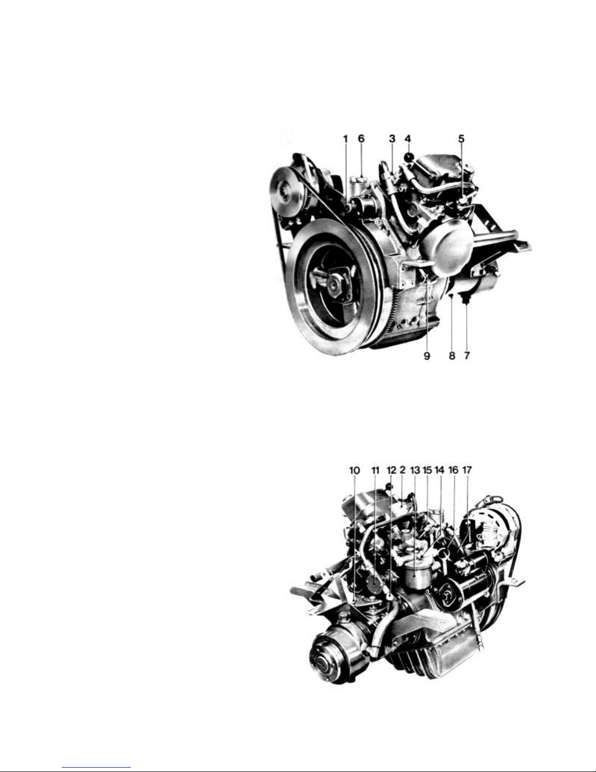
1. Connection for hand start
2. Fuse box
3. Thermostat housing
4. Decompression lever
5. Injector
6. Oil filler Cap, engine
Presentation
7. Water drain tap, gearbox
8. Oil drain plug, gearbox
9. Water drain tap, engine
10. Oil filler, gearbox
11. Sea-water pump
12. Dipstick, gearbox
13. Fuel filter
14. Bleed screw
15. Hand pump, fuel
16. Dipstick, engine
17. Oil filter
2
Repair instructions
Dismantling
1. Drain the cooling water and the oil from the engine. Clean
externally afterwards. Loosen the water hose between the
gearbox and the sea -water pump and remove the gearbox.
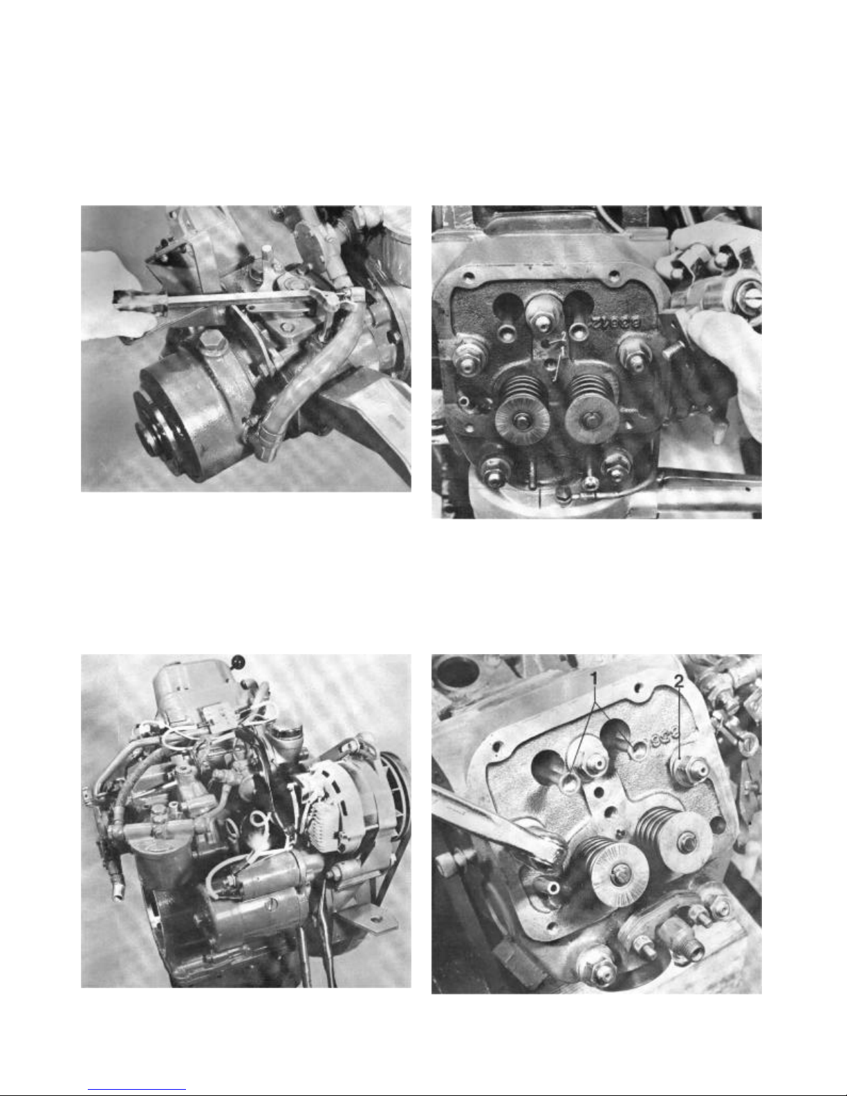
3. Remove the rocker cover and the fuel pipe between the
pump and the injector and unscrew the rocker gear. Note!
Pull the rocker gear straight up since it is centred with a
guide pin 1. The other hole 2 is an oil channel.
2. Remove the generator and its drive belt, starter motor,
fuel filter and fu el pump with the drain-off pipe (be careful of
fuel spillage), coolant water pump with hose and thermostat
housing, dipstick, temperature and oil pressure sensors.
Unscrew and discard the oil filter.
4. Remove the push-rods 1, remove the cylinder head and
the cylinder head gasket. Take care of the washers 2 under
the nuts.
3
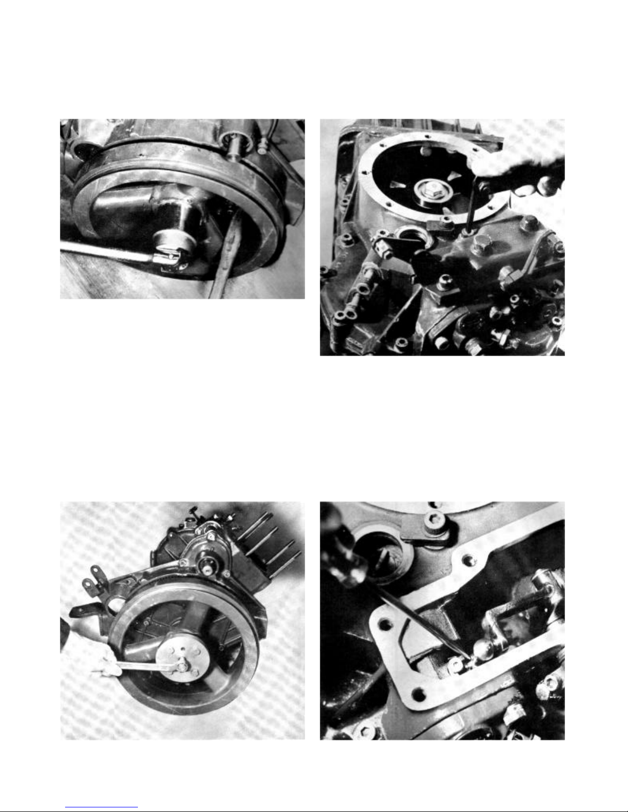
5. Remove the flywheel nuts. Spanner jaw width 55 mm
(2 5/32”). Use a wooden shaft or something similar as a
counter force in the flywheel spokes.
7. Remove the cover for the injection pump. Note! The
bracket for the cold start is fixed with one of the screws.
Take care of the spring under the cover.
6. Fit tool 884078 to the flywheel. Afterwards screw in the
centre screw on the tool until the flywheel loosens.
8. Prise the lower ball joint free from the pump with a
screwdriver.
4
9. Remove the pump screws. Position the ball in the centre
and remove the pump.
11. Remove the governor by loosening the hexagonal set
screw (1), the governor and the gear wheel can then be
withdrawn.
10. Remove the sump and then the transmission cover (13
screws). The lifting eye is fixed one of the screws. The cover
is centralised by guide pins.
12. Remove the screw and the locking washer for the
gearbox drive flange on the crankshaft and remove the
flange with a puller. (Use counter force.) Remove the key
afterwards.
5
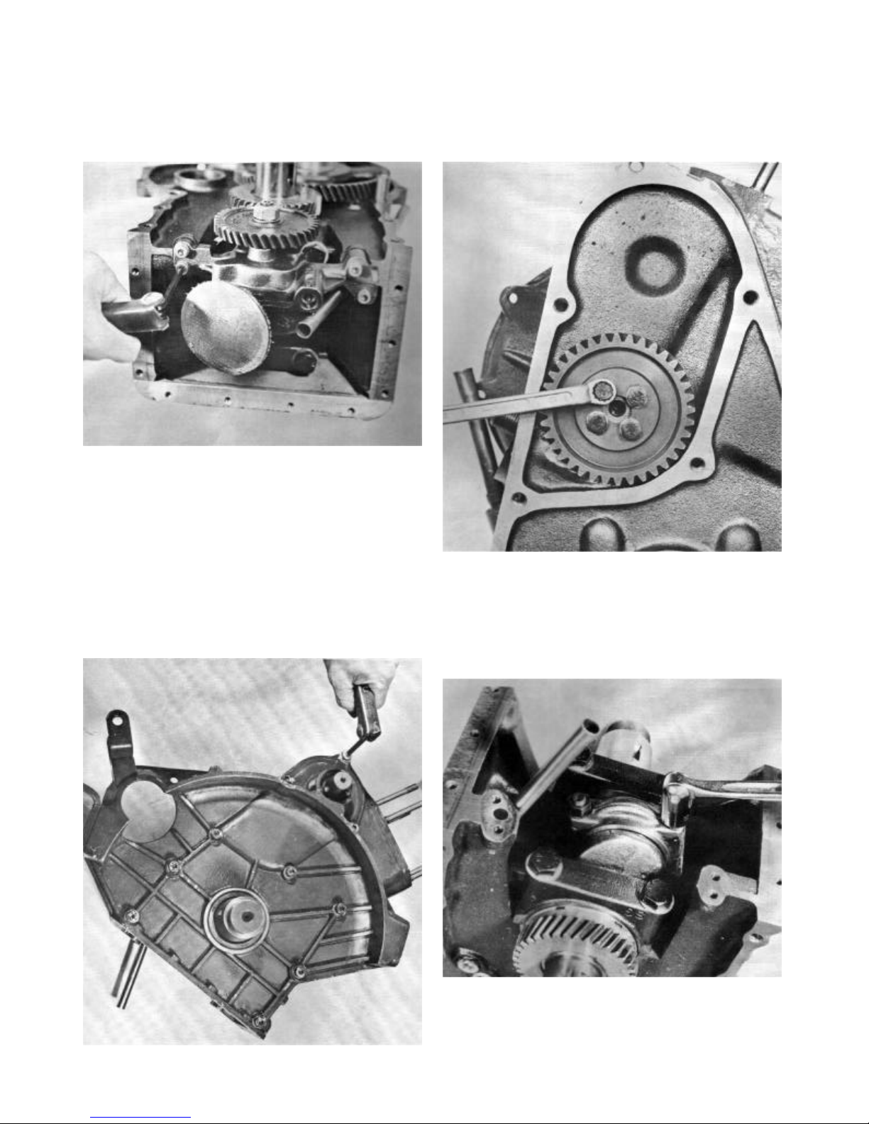
13. Remove the lubricating oil pump. Discard the gasket. 15. Remove the gearwheel on the camshaft’s flywheel side
(4 screws) . Then remove the camshaft and the gearwheel.
14. Remove the cover (flywheel side), 10 screws. The cover
is centred with guide pins. The screws by the guide pins are
fitted with thick washers.
16. Mark and remove the bearing cap on the crankshaft and
carefully knock out the piston through the cylinder.
6
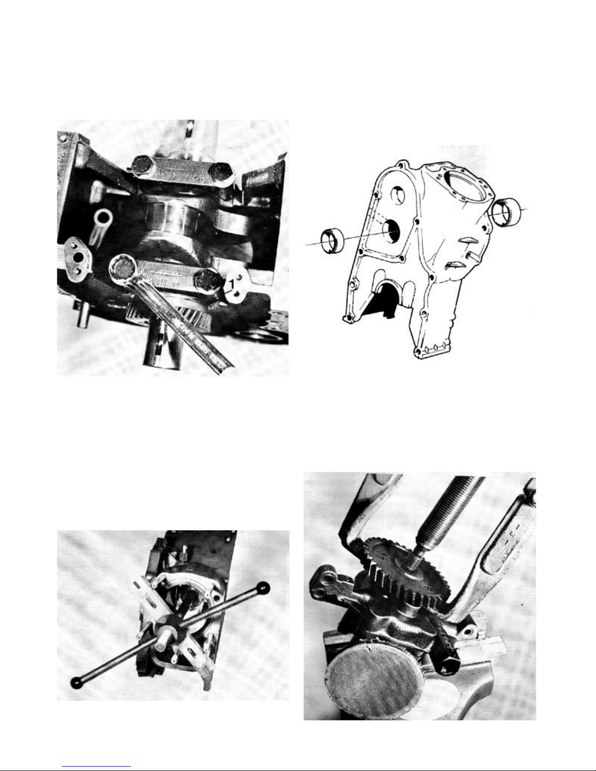
17. Remove the main bearing caps. Take care of the axial
thrust bearings 1 on the transmission side. Lift the crank shaft
out and the bearing shells afterwards and then the axial
bearing halves.
19. Bearing replacement. Press out the camshaft bearings if
they are damaged or if the wear is too great (see technical
data). Clean the bearing housings and ensure that the oil
channels are clean. Press in the new bearings so that the oil
holes face the corresponding oil channels in the block. When
the bearings are pressed in position they are to be reamed
(see technical data).
18. Mark the cylinder liner’s position in the cylinder so that
the same position can be obtained during assembly.
Remove the cylinder liner. Use tool 884551. Use the long
screw and its nut from the tool 884231 (MD21-MD32). See
page 29 Special tools. Discard the 0-ring. Afterwards remove
the 0-rings in the block which provide a seal for the cylinder
liner and then remove the valve lifters. Wash all the parts
and replace those damaged.
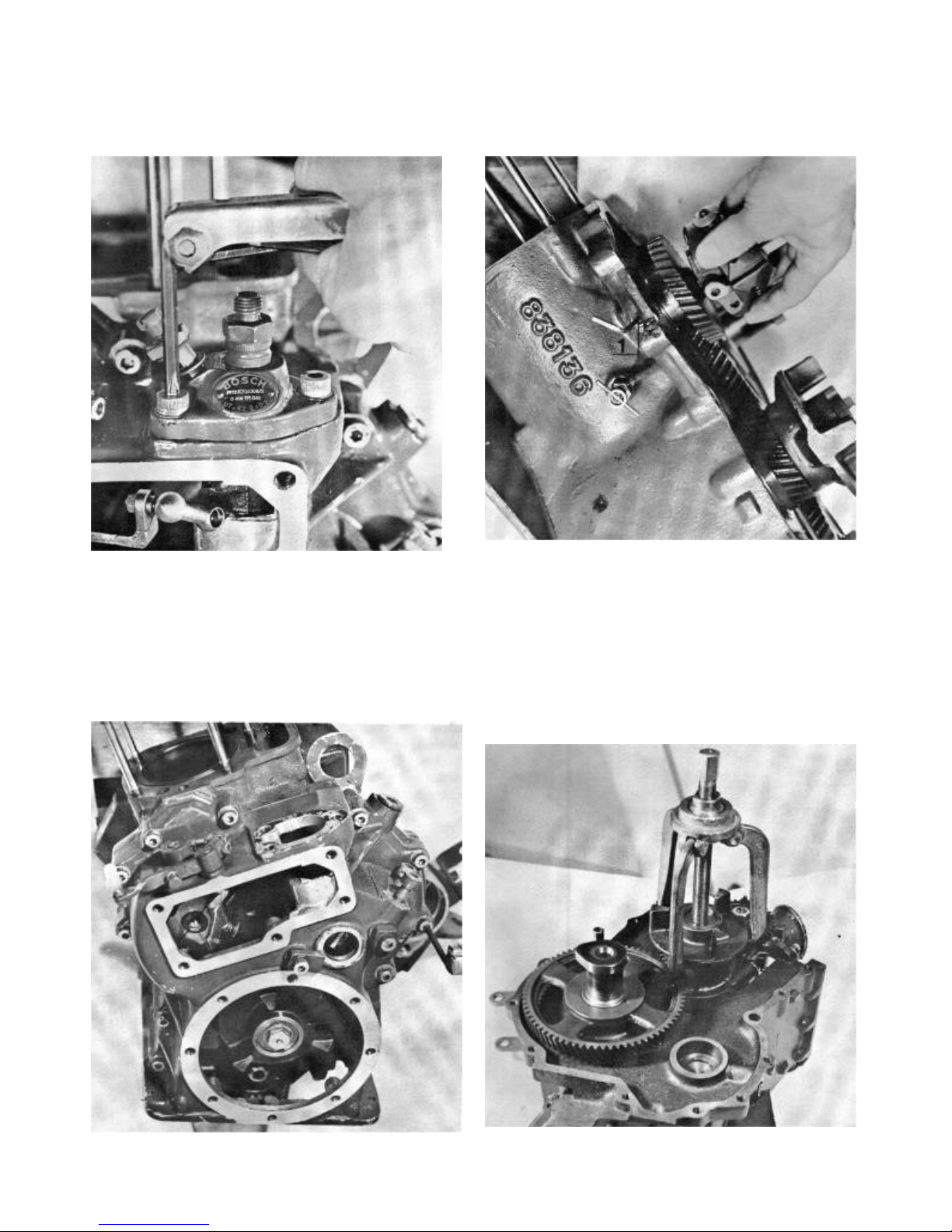
Oilpump
20. Remove the gearwheel’s nuts and pull off the gearwheel
with a puller. The gearwheel sits on a key, take care of this
key.
7
21. Remove the steel wire which holds the filter. Remove
and clean the wire gauze thoroughly. Afterwards remove the
six screws which hold the cover in position. Discard the
gasket.
Overhauling the sea-water pump
23. The sea-water pump is a round flange type pump which
means that it can be fitted in a position best suited to the
coolant water hoses. The new pump is fitted with an 0-ring
which forms a seal against the engine.
22. Remove the gearwheel from the housing. Remove the
split pin for the reduction valve. Remove washer 1, spring 2
and piston 3. Clean and replace damaged parts. Assemble
the lubricating oil pump in the reverse order. Note! Fit a new
gasket 4 between the housing and the cover. Fix the wire
mesh 5 in position with the steel wire 6 and finally lay the key
in position and tighten the gear wheel 7.
24. Remove the cover (6 screws). Change the impeller with
the help of two screwdrivers or something similar. Note!
Protect the edges of the pump housing. See the figure. Prise
out the impeller with the screwdrivers so far that the screw
becomes visible.
8
25. Unscrew the screw and withdraw the impeller from the
shaft. If the sealing rings are to be replaced, the shaft and
the impeller can be removed and the screw subsequently
loosened.
27. Fit new sealing rings. Note! The sealing rings must face
the right way, see that they do not block the drain hole in the
pump housing. Smear grease on the shaft and fit it carefully
in the housing. Screw it through the sealing rings so that
they will not be damaged. Place the shaft so far into the
housing that the hole for the screw is visible. Fit the impeller
and screw in the screw. Then carefully press in the impeller
so that it touches bottom. Place a new gasket on the cover
and tighten the cover with the six screws.
26. Remove the sealing rings 1 and the 0-ring 2 (earlier
engines) and clean the housing and the shaft. (Note! The
pump must be removed from the engine.) Check that there
are no abrasions on the shaft. Note! A new 0-ring is not to be
fitted.
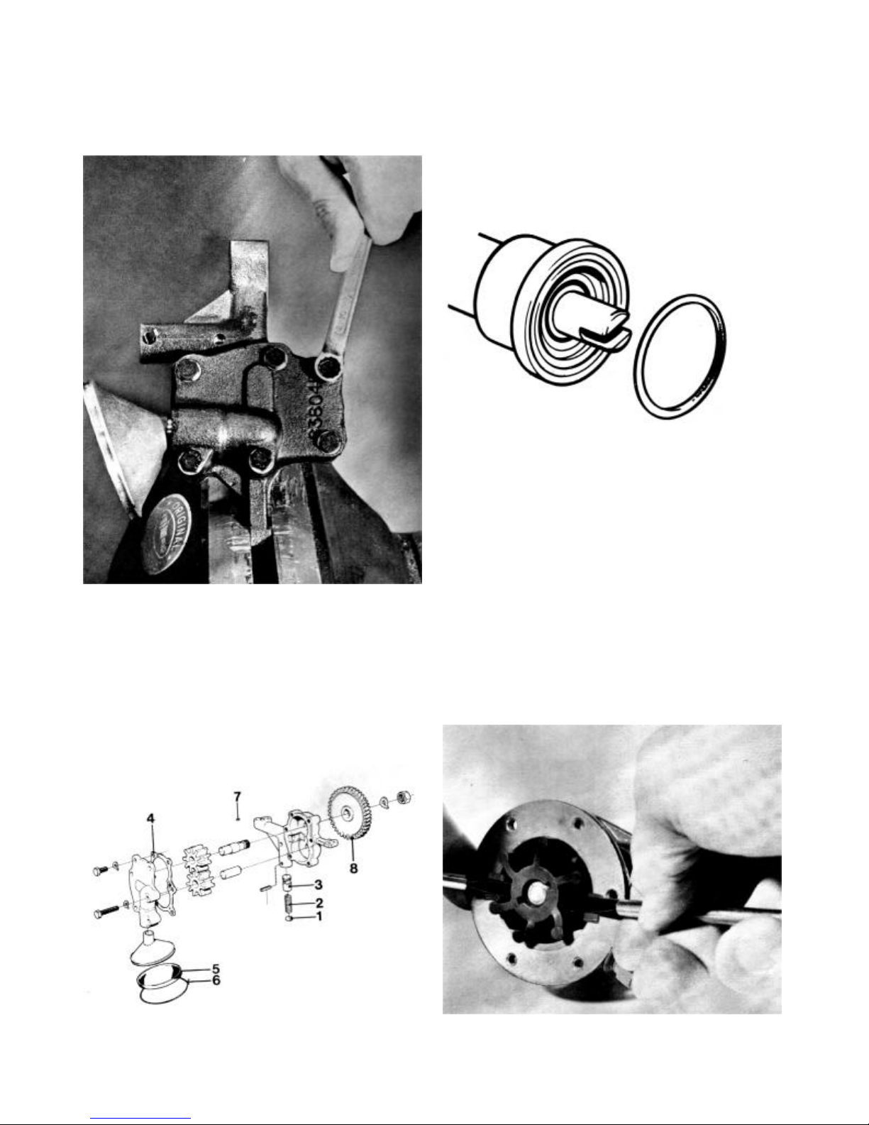
Overhauling the feed pump
28. Depress the pump’s lever (see fig.). If the pump “creaks”
then it is sound. If it is unserviceable the diaphragm must be
replaced which is done in the following manner:
9
29. Remove the cover’s centre screw, remove the filter 1
and clean it.
31. Depress the diaphragm and shake the pump arm
spindle out until the pump arm is free. Then remove the
diaphragm from the housing.
30. Remove the six screws which hold the upper and lower
pump halves together. Remove the pump’s spring and undo
screw 2 which holds the pump arm spindle.
32. Remove screw 1 and withdraw the manual pump arm 2
and replace spring 3 if it is broken. Note! Be careful of the
rubber seal which is pressed into the housing.
10

33. Clean the pump housing carefully and replace worn
parts. Refit the manual pump arm. Press in the diaphragm
and connect the pump arm to the diaphragm centre pin.
Then push the spindle in and tighten it with the screw. Note!
Do not forget the washer under the screw.
Lay the gauze filter on the upper housing and screw the
cover and the gasket tight. Press in the pump arm 3,
assemble the two housing halves and fit the spring retainer 2
on the mechanical pump arm 3. Note that the spring retainer
can only be fitted one way. Replace the spring next and the
0-ring 4 which provides a seal for the engine.
Crankshaft
35. Remove the circlip with circlip pliers. Then remove the
gear drive. Use a press or a gear puller. Clean the
crankshaft and carry out control measurements of all the
bearing surfaces. Grind the shaft where necessary. See
technical data.
Fuel filter
34. When the filter insert is changed the centre screw 1 is
removed allowing the filter holder to be removed. Afterwards
remove the filter insert by lifting the plastic loop 4. Wash the
filter holder clean and fit a new filter. Fit a new packing
washer 5 and refit the holder to the cover with the centre
screw.
36. Place the key in the crankshaft’s key slot. Heat the
gearwheel to approximately 1000C (2120F) (no more) and
press it onto the crankshaft. Note! The marking on the
gearwheel shall face outwards. Refit the circlip on the
crankshaft.
11

Centrifugal governor
37. Clean the governor. Check to see if the weights 2 grip
on their spindle or if there is too much movement between
the spindle and the governor weight. Afterwards check that
the pin 1 slides easily in the spindle. Finally check both the
ball bearings 3. Replace the ball bearings if they are tight.
Check that all the movable parts move easily, lubricate and
refit them in the reverse order.
39. Mark the piston and the connecting rod. Remove the
circlips. Press out the gudgeon pin with a drift. (The piston
can be heated first to ease removal.)
Piston
38. Remove the piston rings with the help of piston ring
pliers. Clean the piston and be particularly careful about the
piston ring grooves.
40. Press the bush out of the connecting rod if it is worn or
damaged. Then knock out the connecting rod screws. Note!
The screws must always be changed when the connecting
rod has been dismantled.
12

41. Knock new screws in place and press a new bush in the
connecting rod. Ensure that the lubricating hole 1 in the bush
aligns with the hole in the connecting rod. Ream or diamond
drill the bush to an accurate free fit. Check that the gudgeon
pin slides through the bush due to its own weight. (See also
the technical data.) Fit one of the circlips and oil the gudgeon
pin and connecting rod bush. Heat the piston to
approximately 700C (1580F) and assemble the piston and
the connecting rod according to the marking. Note! The
gudgeon pin must be able to be pressed in easily. Fit the
other circlip.
43. Fit the piston rings with the help of piston ring pliers.
Start with the oil scraper ring in the lowest groove. The oil
scraper ring can be fitted either way. Continue with the
compression ring which is marked “TOP” on one side. This
marking shall face upwards when fitted. The piston ring with
the chromium insert is fitted last and can be fitted either way.
42. Control the dimensions of the piston with a micrometer.
Measure at right angles to the gudgeon pin holes at the
piston’s lower edge. Afterwards check the new rings’ play in
the piston ring grooves. (See technical data.)
Cylinder head
44. Remove the collets, the collars and the valve springs
with the help of a valve spring compressor. Remove the
valves. Remove the valve seal from the inlet valve. Burnt
valves are discarded if worn too much and damaged seats
are to ne machined when necessary. (See technical data.)
The valves and valve seats are to be ground together so that
the mating surfaces provide a complete seal.
13

Replacing valve guides
45. The valve guides must be replaced if there is too much
play between the valve stem and the valve guide. (See
technical data.) Press out the valve guides with tool 884538.
Nozzle sleeve
47. Remove the injector sleeve with tool 884541. Insert the
expanding screw in the nozzle sleeve and screw anti -clockwise until the screw has expanded and gripped the sleeve.
Tighten hard so that the threads bite into the copper. Fit the
yoke onto the studs which hold the nozzle. Screw on the nut
and tighten until the sleeve is removed.
46. New valve guides are fitted with tool 884549. Use a
press. This tool gives the guide the right height above the
cylinder head’s valve spring seat surface. Check the dimension “A” - this must be 9 mm (0,3543 in.) when the guide is
pressed into place.
48. Remove the 0-ring which provides a seal between the
sleeve and the cylinder head. Clean carefully and dry with
compressed air and then dip the new 0-ring in a soap
solution to facilitate assembly. Lubricate and fit the new
nozzle sleeve with tool 884557. Knock in the sleeve until it
reaches bottom.
14

49. Lubricate the mandrel tool 884537 and insert the tool
into the sleeve. (Ensure that the centre screw is sufficiently
unscrewed.) Place some nuts or several washers on the
studs so that the yoke can be tightened in place with the
fixing nuts. Screw in the mandrel as far as the mating face of
the sleeve allows. The mandrel is then withdrawn. Remove
the tool.
Valve and valve seat grinding
51. Machine the valve seats by milling or grinding them.
Grind no more than is necessary to give the seat the correct
shape and a good mating surface. The seat angle C shall be
45° and the width “B” approximately 1 mm (0,0394 in.). The
width is adjusted with a 39° and a 60 ° miller respectively or
a grinding disc. Clean the valves and grind them in a
machine. The valves’ face angle D shall be 44,5°. The
sealing surface is ground no more than is necessary to
“clean” it. If less than 1 mm (0,0394 in.) is left on the valve
edge it is to be discarded. Likewise the valve is discarded if
the valve stern is not straight or if dimension “A” exceeds 2,5
mm (0,0984 in.). Note! If this dimension is exceeded even if
a new valve is fitted, the cylinder head must be changed.
50. Adjust the length of sleeve protruding from the cylinder
head face, (length is 0,9 mm) (0,0354 in.) and check that the
sleeve is correctly fitted (dimension 19,5 mm). (0,7677 in.).
Rocker mechanism
52. Remove the circlip from the rocker shaft and remove the
rocker arms. Clean the parts. Be particularly careful when
cleaning the rocker shaft oil channels 3 and the rocker arm’s
oil hole, see also fig. 53.
15

53. Check the wear on the rocker shaft. Also check that the
tappet adjustment screw’s spherical part is neither deformed
nor worn. The threads on the screw and the locknut must be
undamaged.
Oval rocker arm bushes are to be replaced. Pressing in and
out is performed with drift 884560. Press the bush in so that
the oil hole assumes the position shown in the figure. The
bush is reamed to a light pus h fit after it has been pressed
in. Lubricate the shaft and assemble the rocker mechanism.
Pressure testing the nozzles
55. Check the shape of the jets at an opening pressure of
185 kp/cm2 (2631 p.s.i.). Also check that the fuel spray
discontinues simultaneously at all four holes and that no
subsequent drops appear.
54. Fit the rubber seal 1 on the inlet valve. Use tool 884497.
Oil the valve sterns before they are inserted in their
respective valve guides. Afterwards fit the valve springs,
collars and collets with the help of a valve compressor.
Adjustment of opening pressure
56. The opening pressure is adjusted with adjustment
washer 1, which is available in thicknesses between 1 mm
(0.0394 in.l and 1,95 mm (0.0768 in.) with a difference of
0,05 (0,0020 in) mm between each size. Dismantle the
nozzle and replace the washer with a thinner or thicker
washer depending on whether the pressure is to be reduced
or increased. Assemble the nozzle and check the opening
pressure and jet shape. Continue until a satisfactory result is
obtained.
16

Flywheel cover and hand starting mechanism
57. Unscrew nut 1 and remove it and washer 2 holding the
hand starting gearwheel 3. Then remove the gearwheel from
the shaft A. Knock the shaft out from the cover. Loosen the
set screw 5 which holds the spacer washer and knock out the
spacer washer when the bearings 7 has been removed.
Remove key 8, slide off the spacer ring 9 and pull off ball
bearing 10 after which seal 11 can be pulled off. Note! If only
the seal 11 is to be changed, pin 12 can be knocked out, after
which the seal can be removed.
58. Replace damaged parts and reassemble the pin, seal,
ball bearing and spacer ring on the shaft. Fit the spacer
washer into the cover and tighten it in position with the set
screw. Note! Ensure that the spacer washer’s groove faces
the locking screw’s centre. Fit the shaft in the cover. Place the
key in position and then the ball bearing. Fit the gearwheel.
Secure it with a washer and nut. Knock out seal 1 from the
flywheel cover. Press in a new seal afterwards.
that the transmission cover must be machined since the
new camshaft gear is thicker than the earlier gear and
consequently there is not enough space for it in the
transmission cover. The axial guide face distance A must be
filed down by 3mm (0,1181 in.).
If the camshaft is damaged this means that the camshaft
gear must be replaced in this case as well. This also means
that the axial guide face must be filed down by 3 mm
(0,1181 in.).
Camshaft
59. In such cases (on engines with engine nos. 100-1075)
where a camshaft gear change is necessary, the camshaft
must be changed as well. A new camshaft gear cannot be
fitted to an early type of camshaft. Furthermore this means
60. If the transmission cover is damaged and must be
replaced, this means that even the camshaft and the
camshaft gear must be replaced. The replacement is
necessary because the axial guide in the new transmission
cover is shortened by 3 mm (0,1181 in.) which in turn
means that the camshaft will have an axial play of 3 mm
(0,1181 in.).
The camshaft, camshaft gear and transmission cover are
interchangable as of engine no. 1076 inclusive. When
changing camshaft gears of a later type, the camshaft shall
be pressed out of the camshaft gear.
Take care of the key. Check the camshaft for wear. See the
technical data.
Place the key in the camshaft and press on the camshaft
gear. The distance from the camshaft end to the camshaft
gear’s hub must be 136 mm (5,354 in.). See fig.
17

ASSEMBLING
61. Check that the liner is not scratched and that it is in
good condition otherwise. Fit new 0-rings 1 in the block (2
off) and a new 0-ring 2 on the cylinder liner. Turn the mark
on the liner (which was made during dismantling) to the mark
on the block. Lubricate the 0-rings and fit the liner. Be careful
not to damage the 0-rings.
63. Place the main bearing halves with the oil channel holes
in the block. Then place the axial bearing halves in position.
Turn the oil grooves 1 outwards.
62. When the cylinder liner is fitted in the block the height of
the liner outside the block must be measured. The height
must not exceed 0,05 mm (0,0020 in.) and must not be less
than 0,01 mm (0,0004 in.), otherwise there is a risk that a
leak can occur.
64. Oil both the bearing halves and place the crankshaft in
position. Fit the main bearing shells in the bearing housings
and place the axial bearings with the oil grooves outwards.
Fit the bearing housing so that the indentation in the housing
faces the same way as the indentation in the bearing half
already in the block. Tighten the bearing housing with a
torque of 70 Nm (7 kpm) (50 Lbft.).
18

65. Remove any wear edges in the cylinder liner. Oil the
cylinder liner and fit the piston in the block. Use a piston ring
sleeve or tool 9992176. Turn the piston so that the machined
depression in the piston crown faces the nozzle side.
67. Fit the camshaft with the camshaft gear. Align the marks
on the crankshaft gear and the camshaft gear.
66. Oil and fit the big end bearing shells in the bearing half.
Turn mark to the correct position and fit the bearing half.
Tightening torque: 70 Nm (7 kpm) (50Lbft.).
68. Fit the governor. Tighten it in position with the set screw
on the side. See that it goes into the groove.
19

69. Fit the gearwheel on the camshaft’s opposite end. 71. Fit a new gasket for the transmission cover. Afterwards
fit the transmission cover. Fix the lifting eye with the upper
screw.
70. Fit the oil pump. Note the different screw lengths.
Adjustment of control rod travel
72. Fit a new gasket and fit the injector pump. Press on the
ball end of the control arm. Measure and check that the
control rod travel is correctly adjusted. (The same as prior to
dismantling.) The measurement must be carrie d out with a
new gasket. Set the control at full throttle. Press down the
plunger to bottom position. Note that the cold start must not
be engaged during measurement. The exact amount
injected can only be determined when checking in a test
bench.
20

73. Release the plunger 8 mm (0,3150 in.) and measure the
distance from the transmission cover face to the adjusting
screw’s contact point on the control arm.
75. If the engine smokes abnormally, the centre screw on
the cover can be loosened and the adjusting screw can be
adjusted until the engine runs smoke free. See the technical
data for the correct injection amount.
74. Measure the adjusting screw’s length and adjust any
eventual deviation so that the plunger stops when released 8
mm. Screw down the cover afterwards.
76. Fit a new gasket and fit the flywheel cover. Be careful so
that the sealing ring is not damaged. Trim the excessive
gasket.
21

77. Fit a plane packing and then fit the sump. Note! On
earlier engines a rubber seal was used. This is to be
replaced by a plane packing.
79. Replace the tappet rods and fit the rocker mechanism.
Check that the guide pin in the cylinder head goes into the
hole in the rocker mechanism.
78. Lubricate and replace the valve lifters. Fit a new cylinder
head gasket and then the cylinder head. Place the washers
under the nuts and tighten the nuts in three stages to 70 Nm
(7 kpm) (50Lbft.). See the tightening sequ ence.
First stage: 10 Nm (1 kpm) (7Lbft.).
Second stage: 40 Nm (4 kpm) (29Lbft.).
Third stage: 70 Nm (7 kpm) (50Lbft.).
80. Lubricate the oil filter rubber seal. Screw in the oil filter
so far that the rubber seal first contacts the engine body.
Afterwards screw in the filter a further half turn. Note!
Tighten by hand. Then fit the feeder pump. Use a new 0 -ring
between the pump and the engine.
22

81. Fit the fuel filter. Place sealing rings on both sides of the
fuel pipe unions.
83. Connect the injector pipe, the temperature and oil
pressure transmitters.
82. Fit the injector. The tightening torque = 10 Nm (1 kpm)
(7Lbft.). Then connect the fuel drain pipe. Note! Place
sealing rings on both sides of the pipe unions.
Thermostat testing
84. Lower the thermostat into hot water and check with a
thermometer if the thermostat opens and closes correctly at
the right temperature. It should start to open at 600C 1400F
and should be fully open at 900C 1940F. If the thermostat is
defective it must be replaced. Clean the thermostat and fit a
new gasket 1. Place the thermostat in the engine and fit the
thermostat housing. Then fit the water pump and connect the
coolant water hose.
23

85. Place the key for the gearbox connecting drive on the
crankshaft on the gearbox side. Heat the connecting drive
and fit it onto the crankshaft. Lock the drive with the large
washer and the lockwasher. Tighten the screw with a torque
wrench. The tightening torque is 70 Nm (7 kpm) (50Lbft.).
Use a counter force. Bend the lockwasher up against the
screw head afterwards.
87. Fit the starter motor and the alternator. Note! Place the
spacer tube correctly and assemble the belt tensioner. Fit
and tension the drive belt so that it can be depressed 3—4
mm (0,1181—0,1575 in) with normal thumb pressure.
86. Place the key for the flywheel in the crankshaft’s key
slot. Fit and tighten the flywheel. Use a counter force in the
spokes of the flywheel. The tightening torque is 500 Nm (50
kpm) (362L bft.). Spanner jaw width is 55 mm (2 5/32”).
Tappet adjustment
88. Turn the flywheel until both tappets function. Turn the
flywheel a further complete turn and adjust the tappets. The
clearance is 0,30 mm (0,0118 in.) for the inlet valve (nearest
flywheel) and 0,35 mm 10,0138 in.) for the exhaust valve
when the engine is hot. Fit the rocker box cover and a new
gasket.
24

INJECTION ANGLE CONTROL
89. A Wilbär tube is used when checking the injection angle.
Fit the Wilbär tube on the pressure pipe nipple.
91. Open the level valve 1 on the measuring apparatus so
that the level lies 25 - 30 mm (1” - 2 3/16”) from the bottom.
Turn the engine in the rotation direction until compression is
felt.
90. Rotate the engine in the correct directi on until the level
tube 1 is full with air-free fuel.
92. If the injection angle does not meet the prescribed
value, the number of washers 1 between the pump housing
and the transmission cover is increased or decreased until
the correct value is obtained. One washer gives a difference
in injection angle of approximately 1°.
25

93. Fit the exhaust elbow and the gearbox. Use new
gaskets. Check that the rubber damper is not damaged.
BLEEDING THE FUEL SYSTEM
94. Fuel system bleeding is always carried out in the
following cases: When the microfilter is changed - when
draining via the drain plug - when cleaning the gauze in the
fuel pump - when the fuel tank has run dry - when fitting an
injector pump - after leaks in or repairs on, the fuel piping when the engine has been out of use for a long time.
Bleeding is carried out as follows:
Open the air bleed screw 1 in the microfilter. Pump up fuel
using the hand pump 2 until clean air-free fuel runs out.
Close the air bleed screw. If the pump effect is poor rotate
the engine until the pump’s drive cam assumes another
position. If the injector pump has been dismantled or, when
the engine is to be started for the first time after renova tion,
the injection pump must be bled. Open the air bleed screw 3
on the injection pump. Pump the hand pump 2 until air-free
fuel runs out. Loosen the pressure connection 4 and rotate
the engine with the starter motor until fuel runs out from the
pressure pipe. Tighten the pressure connection and start the
engine.
ELECTRICAL SYSTEM
IMPORTANT
The following applies to engines fitted with alternators:
1. Do not break the electrical circuit between the
alternator and the battery when the engine is running.
If a main switch is fitted it must therefore not be
turned off until the engine is stopped.
No lead must be disconnected when the engine is
running since this can irreparably damage the charging
regulator.
2. The battery, battery cable and cable terminals are to be
checked regularly. The battery poles are to be properly
clean and the cable terminals are to be tight and well
greased so that a break in the circuit cannot occur. All
other cables are to be properly connected, no loose
connections must occur. The battery’s positive and
negative connections must on no condition be exchanged
when the battery is connected.
3. When starting with an auxiliary battery, check first that it
has the same rated voltage as the standard battery.
Connect the auxiliary battery with positive to positive and
negative to negative. Remove the auxiliary battery when
the engine has started. Notel The cables to the standard
battery must on no condition be disconnected.
4. When carrying out electrical welding on the engine or
associated installation parts the charging regulator’s
cable must be disconnected and insulated first. Afterwards both the battery cable terminals can be removed.
5. When carrying out repairs on the generator, both battery
cable terminals must always be disconnected. The same
applies if the battery is given a quick charge.
6. Never test a connection with a screwdriver or similar tool
to see if it sparks.
26

Wiring Diagram
Cable Marking
Designation Colour mm2 A.W.G.
A White 6 9
B Black 1.5 15
B’ Black 0.6 19
B” Black 0.75 18
C Red 6 9
C’ Red 35 1
C” Red 0.6 19
F Yellow 1.5 15
G Brown 1.5 15
H’ Blue 35 1
I Green/Red 1.5 15
I’ Green/Red 0.75 18
J Green 1.5 15
J’ Green 0.6 19
J” Green 0.75 18
K Blue/Yellow 0.75 18
L White/Red 0.75 18
M Blue/Red 0.75 18
Circuit explanation
1. Extra switch
2. Charging control lamp
3. Temperature warning lamp
4. Oil pressure warning lamp
5. Key switch
6. Warning unit
7. Screw
8. Charging control lamp (for secondary battery
circuit, extra equipment)
9. Place for instruments, extra equipment.
10. Snap connection
11. Starter motor
12. Alternator
13. Fusebox
14. Main switch
15. Battery
16. Temperature sender
17. Oil pressure sender
27

FAULT TRACING
The fault finding chart given below only covers the most common faults which occur.
FAULT Note
Engine will not start
X Main switch not connected, flat battery, cable
X X Empty fuel tank, fuel tap closed, blocked fuel
X X X Water, air or impurities in the fuel.
X X X X
X Boat abnormally loaded, boat bilge fouled with
X X
X Clogged coolant water intake, cooling vanes,
Engine stops
The engine does not reach
the correct speed at full
throttle
The engine runs rough or
vibrates abnormally
The engine becomes
abnormally hot
disconnected.
filter.
Faulty injector.
weedgrowth.
Propeller damaged.
defective pump wheel or thermostat.
A. Check the charge state of the battery with the help of a
hydrometer which shows the specific gravity of the
battery acid. This varies according to the state of the
charge, (see the technical data). (See furthermore
“Electrical system” p. 26.)
B. Change the microfilter by unscrewing the hexagonal
head on the filter holder’s base. The microfilter and its
holder are of a discardable type which means that the old
filter is discarded and a new one fitted. Check that the
face of the cover is completely clean and that the filter
packing is undamaged. Screw the new filter by hand until
the packing contacts the cover. Then tighten the filter a
further half turn. There is a drain plug in the bottom of the
filter holder for draining water and impurities in the fuel.
Bleed the fuel system after draining and after a filter
change and then check for tightness.
Remove the cover on the feed pump and clean the pre filter in diesel oil. Refit the filter with the notches upward
and fit an undamaged packing and tighten the cover.
Bleed the fuel system.
Check and drain when necessary the extra fuel filter if
one is fitted. Look out for spilled fuel.
C. Check the injector with reference to opening pressure,
tightness and jet shape. It is recommended that these
checks be carried out after a maximum operation time of
400 hours or once per season. See also paragraphs 55
and 56.
D. To obtain the best operational economy, the engine
speed should be at least 300 r.p.m. less that the
maximum obtainable during extended running periods.
Note! If the boat has been in the water a considerable
time, the maximum obtainable engine speed can
decrease due to growth on the hull’s underside. Use
growth inhibiting bottom paint.
Check and clean the hull regularly.
E. Check that the propeller blades are whole. If any of the
propeller blades are damaged, the propeller should be
changed. A propeller blade can be out of line (twisted) —
this is very difficult to detect. Place the propeller on a flat
surface and measure the blades. If any blade is twisted
the propeller should be changed.
F. Check the coolant system from the point of view of
leakage, blockage etc.
Check that the thermostat opens at the correct tempera ture. The thermostat can be taken out when the
thermostat housing has been dismantled. See also
paragraph 84.
The pump impeller in the sea water pump is made of
neoprene rubber and can be damaged when the water
supply is cut off, for instance if there is a blockage in the
sea water intake. Paragraphs 23—27 should be followed
when changing a pump impeller and sealing rings. Note)
If the boat is in the water the sea cock must be closed
before the sea water is dismantled. Do not forget to open
the cock again.
See para A
See para B
See para B
See para C
See para C
See para E
See para F
28

Special tools for the MD5A
Part No Designation
884538 Drift for pressing out valve guides
884549 Drift for pressing in valve guides
884557 Drift for pressing in injector sleeve.
884541 Tool for removing injector sleeve.
884537 Drift for copper sleeve.
884551 +
884231
(screw and
nut from
MD21-MD32)
884560 Drift for removing rocker arm bush.
884497 Drift for fitting rubber valve seal.
884543
884535
Tool for removing cylinder liner.
Nipple fixture
Nipple for compression pressure
measurement.
29

TECHNICAL DATA
General
Type designation
Effect (DIN) at 40 r/s (2500 r.p.m.)
No. of cylinders
Bore
Stroke
Displacement, total
Compression ratio
Compression pressure at starter motor speed
Direction rotation, viewed from flywheel
Idling speed
Cylinders
Cylinder liner, wet replaceable
Cylinder diameter, standard mm (in.)
Pistons
Overall height mm (in.)
Height from gudgeon pin centre to piston crown mm (in.)
Piston clearance mm (in.)
Pistons available as standard mm (in.)
Gudgeon pins
Diameter mm (in.)
Inner diameter of gudgeon pin bush mm (in. )
Clearance between gudgeon pin and bush mm (in.)
Piston rings
Number of compression rings
Number of oil rings
The upper compression ring has a chromium insert
Axial piston ring clearance
Upper compression ring mm (in.)
Lower compression ring mm (in.)
Oil scraper ring mm (in.)
Piston ring gap in cylinder
Upper compression ring mm (in.)
Lower compression ring mm (in.)
Oil scraper ring mm (in.)
Crankshaft
Axial clearance (end float) mm (in.)
Main bearings radial clearance mm (in.)
Big end bearing radial clearance mm (in.)
Main bearing journals
Diameter, standard mm (in.)
Diameter, undersized, 0,250 mm (in.) . .
Diameter, undersized, 0,500 mm (in.) . .
Main bearing shells
Thickness, standard mm (in.)
Oversized, 0,250 mm (in.)
Oversized, 0,500 mm (in.)
1) Measured with a Moto Meter, nipple 884535 and fixture 884543.
MD5A
5.5 kW (7.5 b.h.p)
1
84 mm (3.31 in.)
80 mm (3.15 in.)
0,443dm
16,5:1
20 - 22kp/cm2 11 (144 - 159 psi)
Clockwise
9,2 - 10,8 r/s (550 - 650 r/m)
84,000 - 84,015 (3.3071 - 3.3077)
77(3,0315)
49,0 - 49,05 (1.9291 - 1.9311)
0,081 - 0,114 (0.0032 - 0.0045)
83,901 - 83,919 (3.3032 - 3.3039)
25,996 - 26,000 (1.0235 - 1.0236)
25,999 - 26,004 (1.0236 - 1.0237)
0,001 - 0,008 (0.00004 - 0.0003)
2
1
0,070 - 0,102 (0.0028 - 0.0040)
0,050 - 0,082 (0.0020 - 0.0032)
0,030 - 0,062 (0.0012 - 0.0024)
0,30 - 0,50 (0.0118 - 0.0197)
0,30 - 0,50 (0.0118 - 0.0197)
0,25 - 0,50 (0.0098 - 0.0197)
0,05 - 0,30 (0.0020 - 0.0118)
0,040 - 0,096 (0.0016 - 0.0038)
0,040 - 0,096 (0.0016 - 0.0038)
53,987 - 54,000 (2.1255 - 2.1260)
53,737 - 53,750 (2.1156 - 2.1161)
53,487 - 53,500 (2.1058 - 2.1063)
1,968 - 1,980 (0.0775 - 0.0780)
2,093 - 2,105 (0.0824 - 0.0829)
2,218 - 2,230 (0.0873 - 0.0878)
3
(27 cu. in.)
30

Connecting rod journals
Diameter, standard mm (in.)
Diameter, undersized, 0,250 mm (in.)
Diameter, undersized, 0,500 mm (in.)
Big end bearing shells
Thickness, standard mm (in.)
Oversized, 0,250 mm (in.)
Oversized, 0,500 mm (in.)
Connecting rod
Axial clearance (end float) at crankshaft mm (in.)
Camshaft
Axial clearance (end float) mm (in.)
Radial clearance in bearings mm (in.)
Camshaft diameter mm (in.)
Camshaft diameter mm (in.)
Lifting height mm (in.)
Bearing diameter mm (in.)
Bearing diameter mm (in.)
Inlet valve
Valve disc diameter mm (in.)
Valve stem diameter mm (in.)
Valve seat angle
Seat angle in cylinder head
Seat width in cylinder. head mm (in.)
Tappet clearance, hot mm (in.)
Outlet valve
Valve disc diameter mm (in.)
Valve stem diameter mm (in.)
Valve seat angle
Seat angle in cylinder head
Seat width in cylinder head mm (in.)
Tappet clearance, hot mm (in.)
Valve guides
Length, inlet valve mm (in.)
Length, exhaust valve mm (in.)
Inner diameter mm (in.)
Height above cylinder block’s spring face mm (in.)
Clearance, valve stem-valve guide: inlet valve mm (in.)
Clearance, valve stem-valve guide: outlet valve mm (in.)
Valve springs
Length unloaded mm (in.)
Loaded with a force of 170 N (17 kp) (37,5 lb) mm (in.)
Loaded with a force of 300 N (30 kp) (66 lb) mm (in.)
Lubrication system
Engine oil capacity ex. filter (Imp. qts. = US qts.)
Engine oil capacity inc. filter (Imp. qts. = US qts.)
Oil quality according to API system
1st alternative. Above + 100C (5Q0 F) Volvo Penta oil
Double grade
Below + 100C (500F) Volvo Penta oil Single grade
2nd alternative. Viscosity above + 100Cj500F)
Viscosity below + 100 (50~ F)
Oil pressure, hot engine, idling kplcm2 (p.s.i.)
Oil pressure, hot engine, full throttle kplcm2 (p.s.i.)
50,987 - 51,000 (2.0074 - 2.0079)
50,737 - 50,750 (1.9975 - 1.9980)
50,487 - 50,500 (1.9877 - 1.9882)
1,768 - 1,780 (0.0696 - 0.0701)
1,893 - 1,905 (0.0745 - 0.0750)
2,018 - 2,030 (0.0794 - 0.0799)
0,05 - 0,20 (0.0020 - 0.0079)
0,54 - 0,82 (0.0213 - 0.0323)
0,025 - 0,075 (0.0010 - 0.0030)
39,975 - 40,000 (1 .5738 - 1 .5748)
46,975 - 47,000 (1.8494 - 1.8504)
5,8 (0,2283)
40,025 - 40,050 (1.5758 - 1.5768)
47,025 - 47,050 (1.8514 - 1.8524)
34,9 - 35,1 (1.3740 - 1.3819)
7,955 - 7,970 (0.31 32 - 0.31 38)
45,5° (see fig. page 15)
45°
ca 1 (0.0394)
0,30 (0.0118)
27,9 - 28,1 (1.0984 - 1.1063)
7,925 - 7,940 (0.3120 - 0.3126)
44,5° (see fig. page 15)
45°
ca 1 (0.0394)
0,35 (0.0 138)
52 (2.0472)
52 (2.0472)
8,000 - 8,015 (0.3150 - 0.3156)
10,65 - 11,35 (0.4193 - 0.4469)
0,030 - 0,060 (0.00 12 - 0.0024)
0,060 - 0,090 (0 .0024 - 0 .0035)
42,5 (1.6732)
32 (1.2598)
24 (0.9449)
3
2,0 din
2,1 din
3
(1.7 = 2.1)
(1.8 = 2.2)
CD (DS)
SAE 20W/30
SAE l0W
SAE 20
SAE 10
1,5 - 2,5 kplcm
4,0 - 5,0 kplcm
2
(21 - 36)
2
(57 - 71)
31

Lubrication oil filter
Designation
Lubrication oil pump
Type
Spring for pressure reduction valve: Length unloaded
mm (in.)
Loaded with 25 N (2,5 kp) (5,5 lb) mm (in). .
Loaded with 35 N (3,5 kp) (7,7 lb) mm (in.) .
Gear’s axial clearance including packing mm (in.)
Fuel system
Injector pump, Bosch
Injector, Bosch, holder
Nozzle
Hole diameter mm (in.)
Opening pressure (new nozzle) kp/cm2 (p.s.i.)
Nozzle angle
Pre-injection angle
Fuel quantity injected
Micro Filter
Type
Filter element
Feed pump
Type
Feed pressure at 42 r/s (2500 r.p.in) kp/cm2 (p.s.i)
Electrical system
Battery voltage
Battery capacity
Alternator rating, max
Starter motor rating
Battery electrolyte spec. gray: Fully charged battery
Charging to be carried out at
Cooling system
Thermostat
Starts to open at0C (0F)
Fully open at 0C (0F)
WEAR TOLERANCES
Cylinders (liner)
Replaced when worn (or if the engine has an abnormally
high oil consumption) mm (in.)
Crankshaft
Main and big end bearings
Permissible ovality mm (in.)
Permissible conicity mm (in.)
Max. axial clearance (end float) mm (in.)
Camshaft
Bearing journals, permissible ovality tom (in.)
Max. clearance between camshaft and bearings mm (in.)
Valves
Max. clearance between valve guide and valve stem mm
(in.)
Valve disc edge mm. thickness mm (in.)
MANN W 77 or FRAM PH3614
Gear pump
40 (1.5748)
34 (1.3386)
31,5 (1.2402)
0,010 - 0,130 (0.0004—0.0051)
PFR 1K 70A 431/11
KBAL 65
DLLA 150
Four, 0,23 (0.0091)
185 (2631)
150°
25 - 28°
31 min3/stroke at 33,3 r/s (2000 r.p.m)
Bosch 0 450 015 003
Bosch 1 457 431 324
Pierburg PE 15672
0,65 - 0,85 (9.2 - 12.1)
12 V
Max. 60 Ah
35 A
0,81 kW (1.1 hp)
1,275 - 1,285 g/cm3
1,230 g/cm3
Bellows thermostat
60 (140)
90 (194)
0,25 (0.0098)
0,06 (0.0024)
0,05 (0.0020)
0,36 (0.0142)
0,03 (0.0012)
0,15 (0.0059)
0,16 (0.0063)
1,0 (0.0394)
32

TIGHTENING TORQUES
Cylinder head nuts*
Cylinder head studs
Screw for a gearbox drive on crankshaft
Flywheel nut
Big end (connecting rod) bearings
Water pump drive
Main bearings
Nuts for injector holder
Tightening torque for cylinder head nuts.
* Note! The tightening must be done in three stages.
First stage: 10 Nm (1 kpm) (7Lbft.)
Second stage: 40 Nm (4 kpm) (29Lbf t.)
Final stage: 70 Nm (7 kpm) (50Lbft.)
70 Nm (7 kpm) (50Lbft.)
20 Nm (2 kpm) (14Lbft.)
80 Nm (8 kpm) (58 Lbft.)
500 Nm (50 kpm) (362Lbft.)
70 Nm (7 kpm) (50Lbft.)
60 Nm (6 kpm) (43Lbft.)
70 Nm (7 kpm) (50 Lbtt.)
10 Nm (1 kpm) (7Lbft.)
33

34

35

 Loading...