How it Works
Log In / Sign Up
Buy Points
How it Works
FAQ
Contact Us
Questions and Suggestions
Users
VOLTCRAFT
Loading...
V
VC130-1
7
VC135
7
VC1400A
4
vc150
7
VC150-1
7
VC155
7
VC165
9
vc170
7
VC170-1
8
VC175
6
VC175 SE
VC185
6
VC185 TRMS
4
VC190
3
VC20
11
VC2020
6
VC209-Li
5
VC240
VC250
7
VC251TRMS
4
VC265
8
VC265 - V06-10
VC270
8
VC271 SE
3
VC275TRMS
6
VC276
4
VC276 SE
3
VC280
8
VC290
9
VC35
6
VC36
4
VC40
6
VC4000
3
VC5070
5
VC55 LCD SE
4
VC585
5
VC605
10
VC607
10
VC610BT
VC611BT
2
VC65
6
VC650BT
4
VC810
5
VC820-1
4
VC830
6
VC850
10
VC86
7
vc870
8
VC880
5
VC890 SE
2
VC920
9
VC920 - V06-09
VC930
3
VC940
14
VC950
6
VC960
10
VCW 12000
9
VDO-2052
6
VDO-2072
6
VDO-2072A
5
VDO-2102
6
VDO-2102A
5
VDO-2152A
5
VIT 1000
VIT 500
VLP 1302 A
4
VLP-1303 OVP
2
VLP 1303pro
4
VLP 1303 USB
4
VLP-1405 OVP
2
VLP 1405 Pro
3
VLP 1405 USB
4
VLP-1602 OVP
2
VLP 1602pro
3
VLP 1602 USB
4
VLP 2403
3
VLP-2403 OVP
2
VLP 2403 Pro
3
VLP-2602 OVP
2
VLP OVP FRONT BOARD
VLP Series
VMA-3L 16
4
VMA-3L 32
4
VMA-5LS 16
3
VOLTSOFT
VoltSoft PRO
6
VPT-100
4
VSM-101
4
VSM-102
2
VSM-103
VSM 105
2
VSM-105-100
VSM-105-60
VSM-120
4
VSM-150 100A ZS
4
VSM-150 60A ZS
4
VSP 1220
2
VSP 1220 HE
3
VSP 1410
2
VSP 1410 HE
3
Loading...
Loading...
Nothing found
VC920
Calibration Instruction
16 pgs
199.92 Kb
1
OPERATING INSTRUCTIONS
60 pgs
638.94 Kb
2
User guide [cs]
12 pgs
402.35 Kb
0
User guide [de]
16 pgs
308.12 Kb
0
User guide [hu]
8 pgs
171.88 Kb
0
User guide [ml]
104 pgs
958.78 Kb
0
User guide [ml]
36 pgs
605.75 Kb
0
User guide [ml]
122 pgs
1.42 Mb
0
User guide [pl]
33 pgs
850.05 Kb
0
Table of contents
Loading...
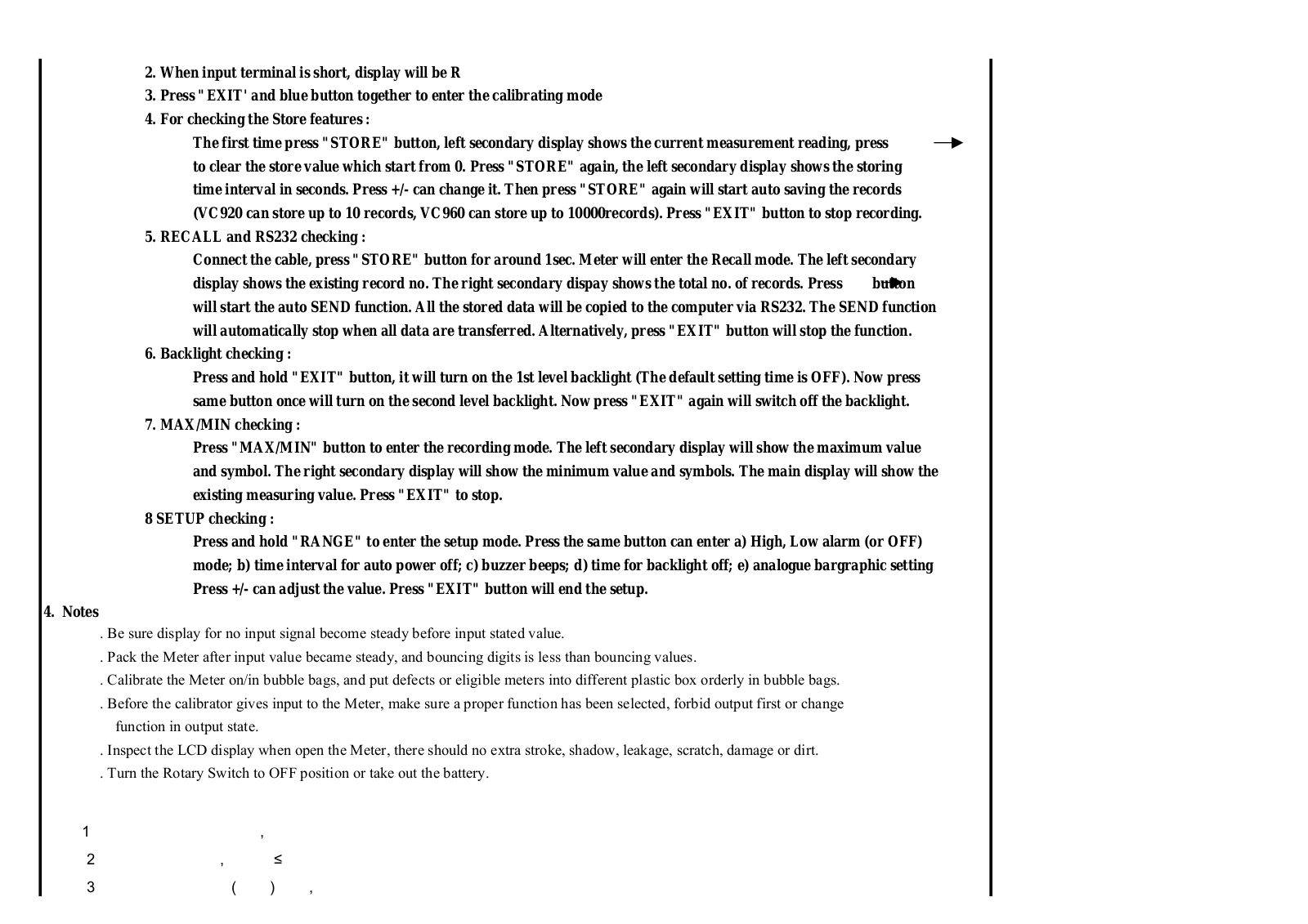
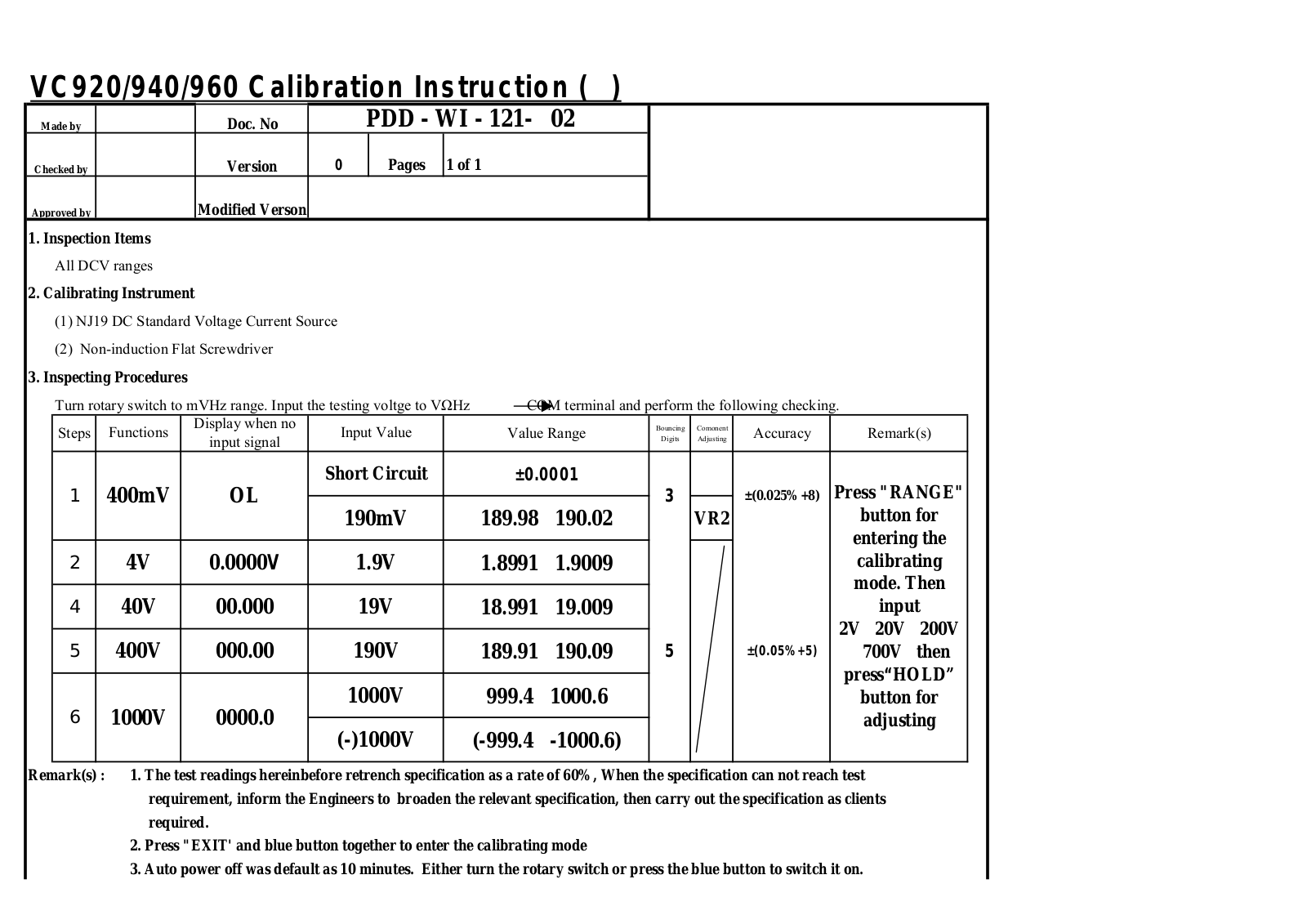
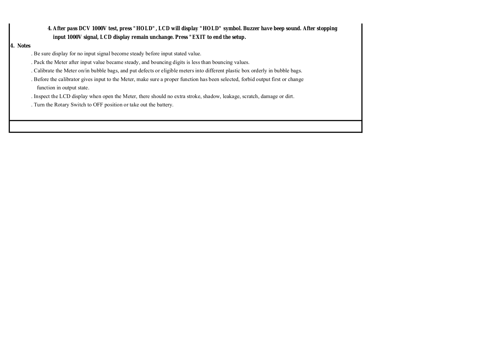
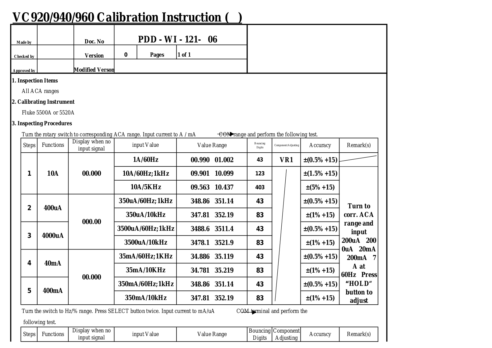
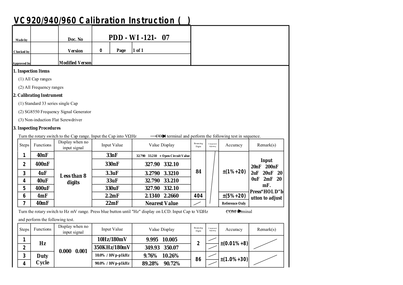
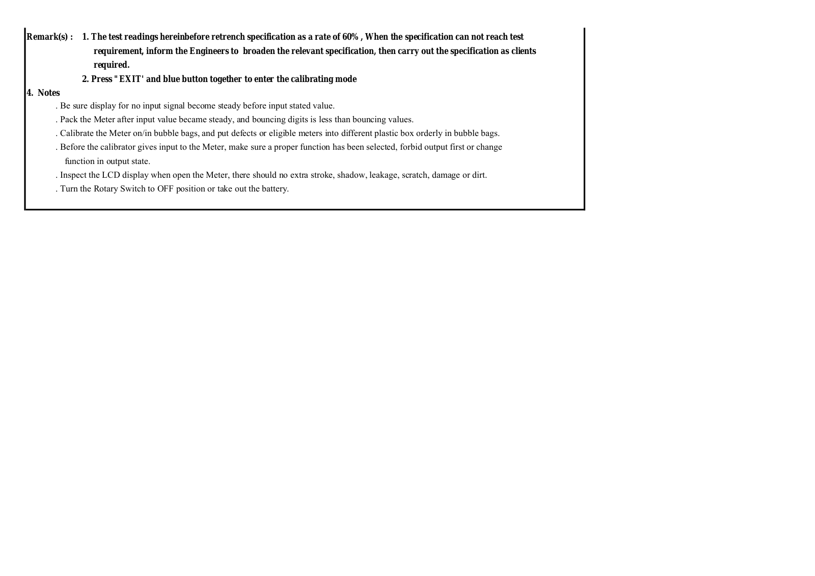
VOLTCRAFT VC920, VC940, VC960 Calibration Instruction
...
VOLTCRAFT Calibration Instruction
Download
Specifications and Main Features
Frequently Asked Questions
User Manual
Download
Loading...
+
hidden pages
Unhide
You need points to download manuals.
1 point = 1 manual.
You can buy points or you can get point for every manual you upload.
Buy points
Upload your manuals