


VIVOTEK - A Leading Provider of Multimedia Communication Solutions
2 - User's Manual
Table of Contents
Overview.......................................................................................................................................................3
Read before use ��������������������������������������������������������������������������������������������������������������������������������������3
Package contents ������������������������������������������������������������������������������������������������������������������������������������3
Physical description ���������������������������������������������������������������������������������������������������������������������������������4
Installation ....................................................................................................................................................6
Hardware installation �������������������������������������������������������������������������������������������������������������������������������6
Network deployment ��������������������������������������������������������������������������������������������������������������������������������7
Software installation ������������������������������������������������������������������������������������������������������������������������������10
Accessing the Network Camera .................................................................................................................11
Using web browsers ������������������������������������������������������������������������������������������������������������������������������11
Using RTSP players ������������������������������������������������������������������������������������������������������������������������������13
Using 3GPP-compatible mobile devices �����������������������������������������������������������������������������������������������14
Using VIVOTEK recording software ������������������������������������������������������������������������������������������������������15
Main Page ..................................................................................................................................................16
Client Settings ............................................................................................................................................19
Conguration ..............................................................................................................................................21
System ��������������������������������������������������������������������������������������������������������������������������������������������������22
Security �������������������������������������������������������������������������������������������������������������������������������������������������24
HTTPS ��������������������������������������������������������������������������������������������������������������������������������������������������25
Network �������������������������������������������������������������������������������������������������������������������������������������������������30
DDNS ����������������������������������������������������������������������������������������������������������������������������������������������������40
Access list ���������������������������������������������������������������������������������������������������������������������������������������������42
Video �����������������������������������������������������������������������������������������������������������������������������������������������������45
Motion detection ������������������������������������������������������������������������������������������������������������������������������������51
Camera tampering detection �����������������������������������������������������������������������������������������������������������������54
Homepage layout ����������������������������������������������������������������������������������������������������������������������������������55
Application ���������������������������������������������������������������������������������������������������������������������������������������������58
Recording ����������������������������������������������������������������������������������������������������������������������������������������������71
System log ���������������������������������������������������������������������������������������������������������������������������������������������74
View parameters �����������������������������������������������������������������������������������������������������������������������������������75
Maintenance ������������������������������������������������������������������������������������������������������������������������������������������76
Appendix ....................................................................................................................................................80
URL Commands of the Network Camera ����������������������������������������������������������������������������������������������80
Technical Specications ����������������������������������������������������������������������������������������������������������������������116
Technology License Notice ������������������������������������������������������������������������������������������������������������������117
Electromagnetic Compatibility (EMC) ��������������������������������������������������������������������������������������������������118

VIVOTEK - A Leading Provider of Multimedia Communication Solutions
User's Manual - 3
Overview
VIVOTEK IP7330 is a cost-effective bullet network camera designed for outdoor applications�
With a weather-proof IP66-rated housing, the camera can be shielded from rain and dust�
By integrating the components for day and night functions into one compact design, IP7330
provides an all-in-one solution, without the need for additional accessories� Equipped with a
dual-band lens and built-in IR illuminators with an effective range of up to 10 meters, IP7330
is able to achieve day and night performance� IP7330 supports tamper detection, which can
detect events from blockage, redirection and spray-painting, making IP7330 an intelligent
solution to camera tampering� IP7330 also incorporates numbers of advanced features including
simultaneous dual streams, dual-codec, 802�3af compliant PoE and free-bundled 16-channel
recording software�
Read before use
The use of surveillance devices may be prohibited by law in your country� The Network Camera
is not only a high-performance web-ready camera but also can be part of a exible surveillance
system� It is the user’s responsibility to ensure that the operation of such devices is legal before
installing this unit for its intended use�
It is important to rst verify that all contents received are complete according to the Package
contents listed below� Take notice of the warnings in Quick Installation Guide before the Network
Camera is installed; then carefully read and follow the instructions in the Installation chapter to
avoid damages due to faulty assembly and installation� This also ensures the product is used
properly as intended�
The Network Camera is a network device and its use should be straightforward for those who
have basic network knowledge� It is designed for various applications including video sharing,
general security/surveillance, etc. The Conguration chapter suggests ways to best utilize the
Network Camera and ensure proper operations� For the creative and professional developers,
the URL Commands of the Network Camera section serves to be a helpful reference to
customize existing homepages or integrating with the current web server.
Package contents
■ IP7330
■ Liquid tight connectors (3 holes, for backup use)
■ Silica gel
■ Camera stand
■ Power adapter
■ RJ45 female/female coupler
■ Quick installation guide
■ Warranty card
■ Software CD x 2
VIVOTEK - A Leading Provider of Multimedia Communication Solutions
4 - User's Manual
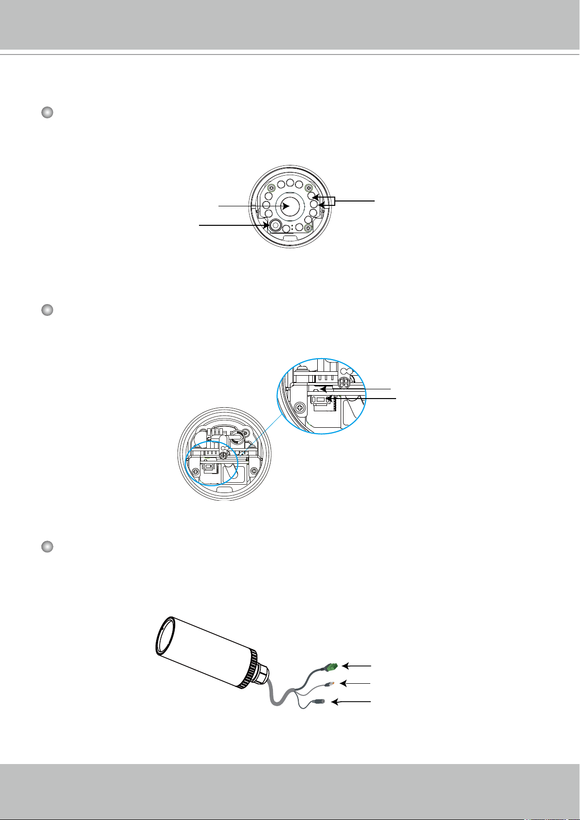
Physical description
Front Panel
Back Panel
Light sensor
Lens
IR LED
Status LED
Reset button
Connectors
General I/O terminal block
Ethernet 10/100 RJ45 plug
Power cord socket (black)
VIVOTEK - A Leading Provider of Multimedia Communication Solutions
User's Manual - 5
AV24V
AC24V
DI
GND
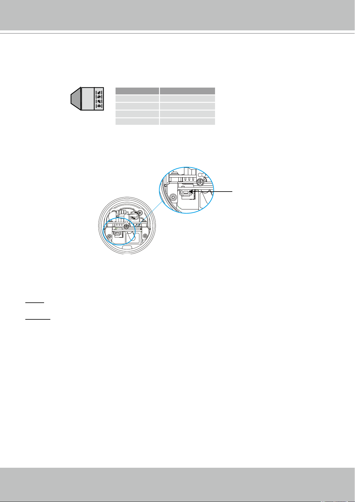
General I/O Terminal Block
This Network Camera provides a general I/O terminal block which is used to connect external
input / output devices. The pin denitions are described below.
Pin Name
AV24V 24V+
AC24V 24V-
DI Digital Iutput
GND Ground
Hardware Reset
Reset button
The reset button is used to reset the system or restore the factory default settings� Sometimes
resetting the system could set the system back to normal state� If the system problems remain
after reset, restore the factory settings and install again�
Reset: Press and release the reset button with a needle� Wait for the Network Camera to reboot�
Restore: Press on the reset button continuously for over 5 seconds� Note that all settings will be
restored to factory default�
VIVOTEK - A Leading Provider of Multimedia Communication Solutions
6 - User's Manual
1
2
3
Silica gel
6
5
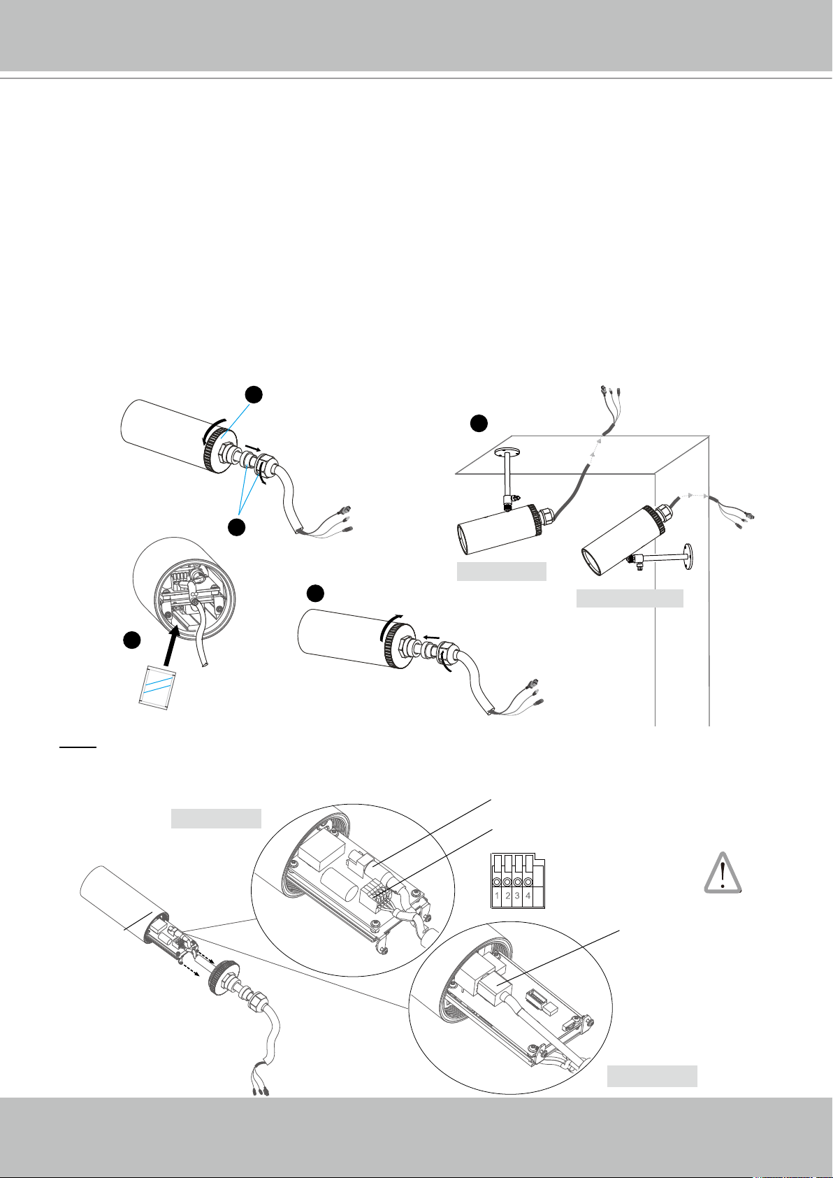
Installation
Hardware installation
1� Loose the liquid tight connectors, and then remove the rubber�
2� Loose the back cover�
3� Tear down the aluminum foil vacuum bag and take out the silica gel� Attach the supplied silica
gel to the inner side of the Network Camera� (Please replace the silica gel with a new one if
you open the back cover after installation�)
4� Make sure all cable lines are securely connected�
5� Tighten the back cover, rubber and liquid tight connectors�
6� Secure the Network Camera to the wall/ceiling by the supplied camera stand�
Wall mount
Ceiling mount
Note
If you want to use your own cable lines, please loose two supplied screws and take out the
power board� Then be careful to make connections as the illustration below�
Power cord
Upper side
Screws
Terminal block (from left to right)
1: AV24V (red)
2: AC24V (red)
3: DI (white)
4: GND (black)
Ethernet cable
Bottom side
VIVOTEK - A Leading Provider of Multimedia Communication Solutions
User's Manual - 7
POW
ER
C
O
LL
I
S
ION
L
I
N
K
RE
CEIVE
PARTITIO
N
1
2
3
4
5
AV24V
AC24V
DI
GND
IP address : 192.168.0.3
Subnet mask : 255.255.255.0
Default router : 192.168.0.1
IP address : 192.168.0.2
Subnet mask : 255.255.255.0
Default router : 192.168.0.1
LAN (Local Area Network)
Router IP address : 192.168.0.1
WAN (Wide Area Network )
Router IP address : from ISP
Cable or DSL Modem
POWER
COLLISION
LINK
RECEIVE
PARTITION
1
2
3
4
5
Internet
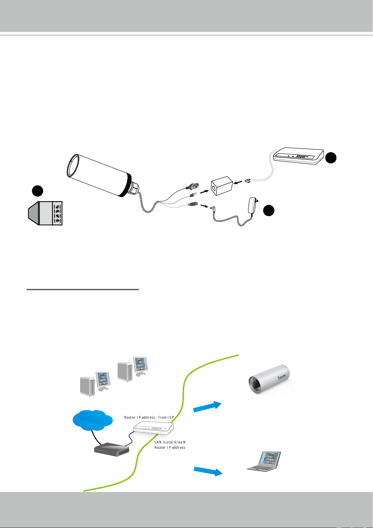
Network deployment
Setup the Network Camera over the Internet
This section explains how to congure the Network Camera to Internet connection�
1. If you have external devices such as sensors and alarms, make connection from general I/O
terminal block�
2� Use the supplied RJ45 female/female coupler to connect the Network Camera to a switch.
Use Catagory 5 Cross Cable when Network Camera is directly connected to PC�
3� Connect the power cable from the Network Camera to a power outlet�
2
1
AV24V: 24V+
AC24V: 24VDI : Digital Input
GND: Ground
3
There are several ways to setup the Network Camera over the Internet� The rst way is to setup
the Network Camera behind a router� The second way is to utilize a static IP� The third way is to
use PPPoE�
Internet connection via a router
Before setting up the Network Camera over the Internet, make sure you have a router and follow
the steps below�
1� Connect your Network Camera behind a router, the Internet environment is illustrated as
below� About how to get your IP address, please refer to Software installation on page 10 for
details�

VIVOTEK - A Leading Provider of Multimedia Communication Solutions
8 - User's Manual
POWER
COLLISION
LINK
RECEIV E
PARTITION
1
2
3
4
5
2� In this case, if the Local Area Network (LAN) IP address of your Network Camera is
192�168�0�3, please forward the following ports for the Network Camera on the router�
■ HTTP port
■ RTSP port
■ RTP port for audio
■ RTCP port for audio
■ RTP port for video
■ RTCP port for video
If you have changed the port numbers on the Network page, please open the ports accordingly
on your router� For information on how to forward ports on the router, please refer to the user’s
manual of your router�
3� Find out the public IP address of your router provided by your ISP (Internet Service Provider)�
Use the public IP and the secondary HTTP port to access the Network Camera from the
Internet� Please refer to Network Type on page 30 for details�
Internet connection with static IP
Choose this connection type if you are required to use a static IP for the Network Camera�
Please refer to LAN on page 30 for details�
Internet connection via PPPoE (Point-to-Point over Ethernet)
Choose this connection type if you are connected to the Internet via a DSL Line� Please refer to
PPPoE on page 31 for details�
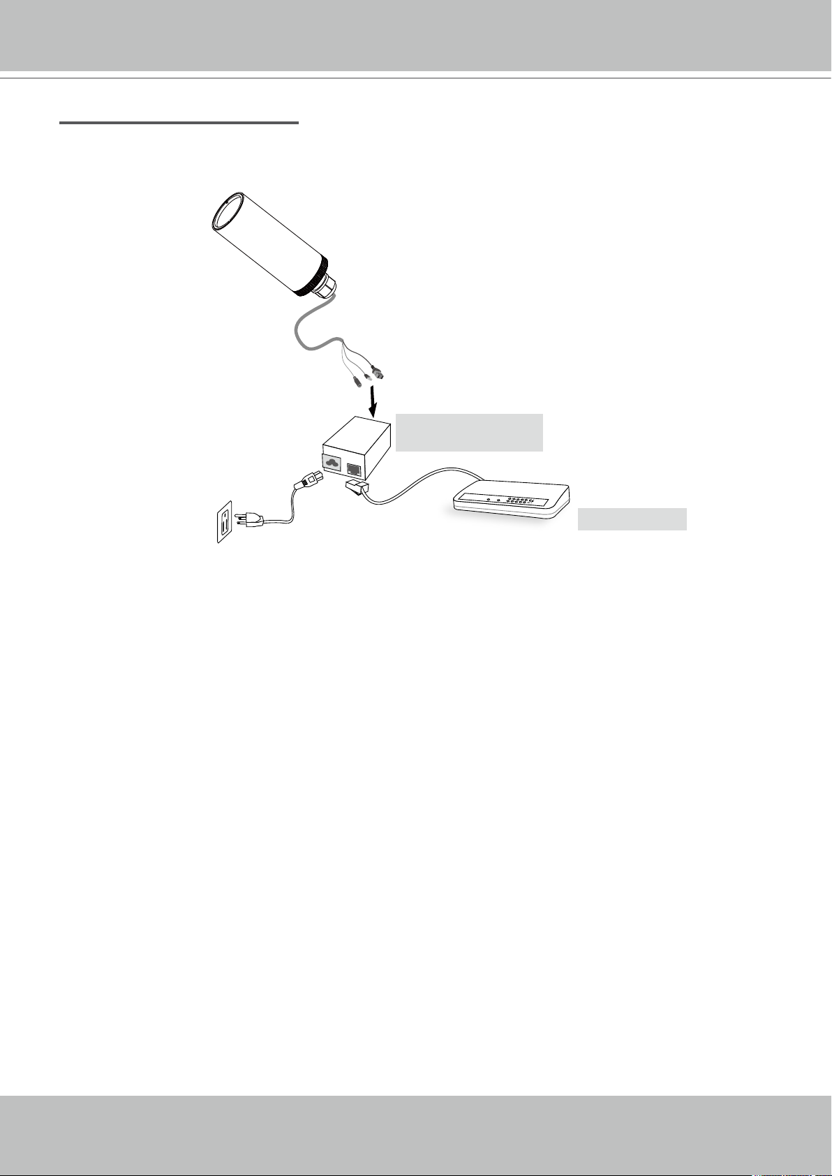
Set up the Network Camera through Power over Ethernet (PoE)
When using a PoE-enabled switch
The Network Camera is PoE-compliant, which allows it to be powered via a single Ethernet
cable� If your switch/router supports PoE, refer to the following illustration to connect the
Network Camera to a PoE-enabled switch/router via an Ethernet cable�
power + data transmission
PoE switch
VIVOTEK - A Leading Provider of Multimedia Communication Solutions
User's Manual - 9
POWER
COLLISION
LINK
RECEIV E
PARTITION
1
2
3
4
5
When using a non-PoE switch
If your switch/router does not support PoE, use a PoE power injector (optional) to connect
between the Network Camera and a non-PoE switch/router�
PoE power injector
(optional)
non-PoE switch
VIVOTEK - A Leading Provider of Multimedia Communication Solutions
10 - User's Manual
0002D1733012
Network Camera
Model No: IP7330
Made in Taiwan
This device complies with part 15 of the FCC rules. Operation is subject to the following two conditions:
(1)This device may not cause harmful interference, and
(2) this device must accept any interference received, including interference that may cause undesired operation.
Pat. 6,930,709
RoHS
MAC:0002D1733012
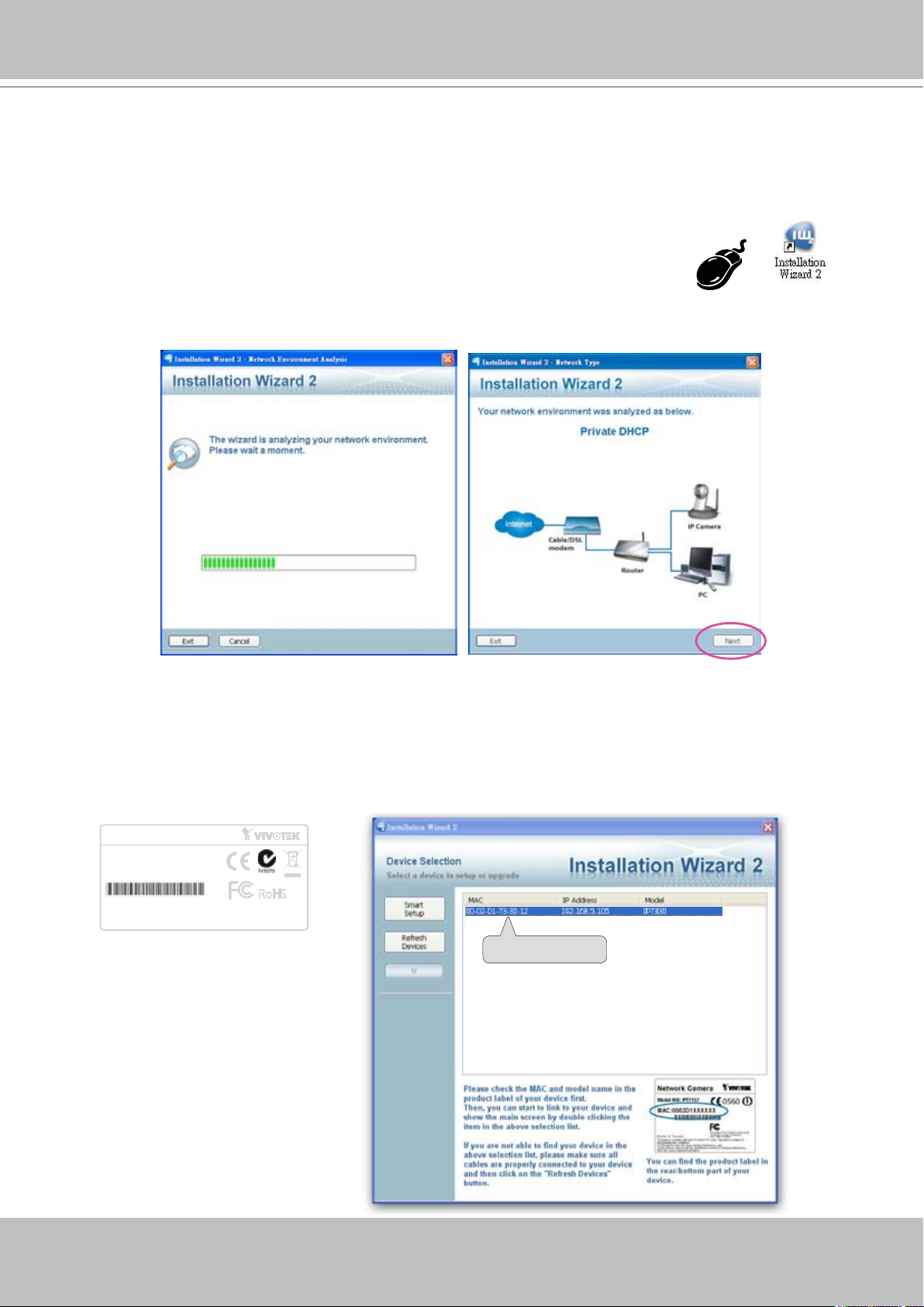
Software installation
Installation Wizard 2 (IW2), free-bundled software packaged in the product CD, helps to set up
your Network Camera in LAN�
1� Install the IW2 under the Software Utility directory from the software CD�
Double click the IW2 shortcut on your desktop to launch the program�
2� The program will conduct analyses on your network environment�
After your network environment is analyzed, please click Next to continue the program.
3� The program will search all VIVOTEK devices in the same LAN�
4� After searching, the main installer window will pop up� Click on the MAC and model name
which match the product label on your device to connect to the Network Camera via the
Internet Explorer.
VIVOTEK - A Leading Provider of Multimedia Communication Solutions
User's Manual - 11
Accessing the Network Camera
This chapter explains how to access the Network Camera through web browsers, RTSP players,
3GPP-compatible mobile devices, and VIVOTEK recording software�
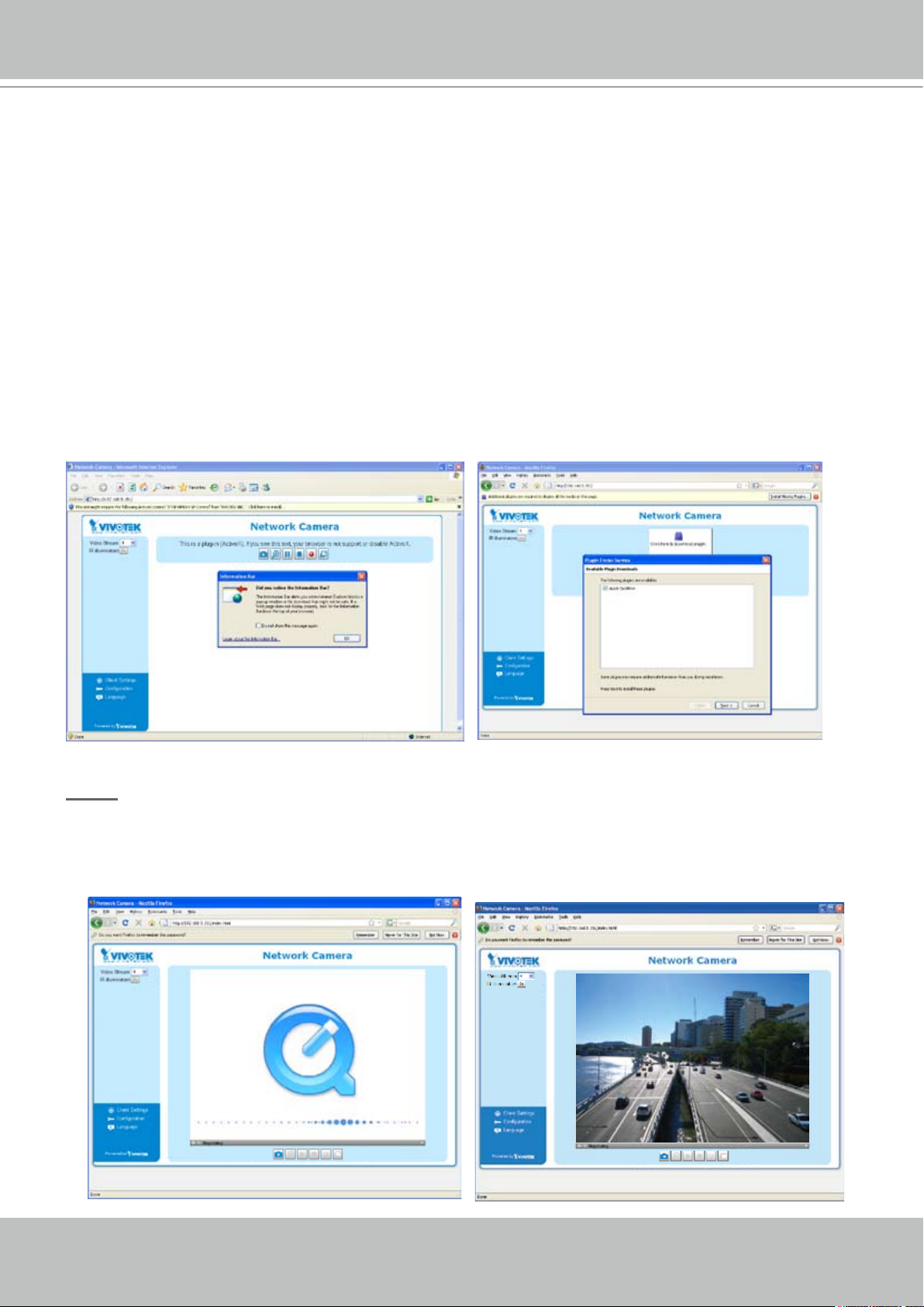
Using web browsers
Make use of Installation Wizard 2 (IW2) to access to the Network Cameras in LAN.
If your network environment is not in LAN, follow the steps to access the Network Camera:
1. Launch your web browser (ex. Microsoft
2. Enter the IP address of the Network Camera in the address eld. Press Enter�
3� The live video will be displayed in your web browser�
4. If it is the rst time for you to install VIVOTEK’s network camera, some information bar will
pop up as below� Follow the instruction to install required plug-in on your computer�
®
Internet Explorer, Mozilla Firefox or Netscape).
NOTE
► For Mozilla Firefox or Netscape users, your browser will use Quick Time to stream the live
video. If you don’t have Quick Time on your computer, please download it rst, and then
launch the web browser�
VIVOTEK - A Leading Provider of Multimedia Communication Solutions
12 - User's Manual
► By default, the Network Camera is not password-protected. To prevent unauthorized
accesses, it is highly recommended to set a password for the Network Camera�
For more information about how to enable password protection, please refer to Security on
page 24�
®
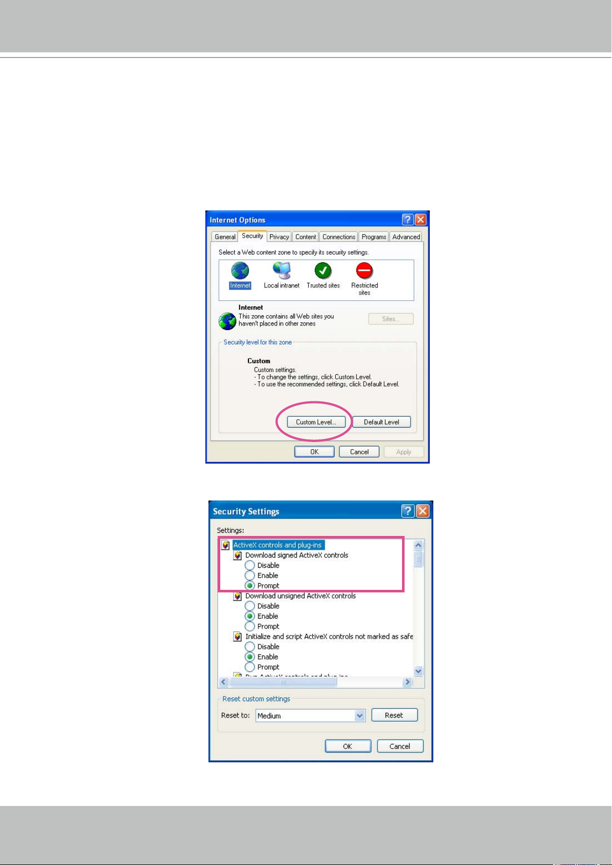
► If you see a dialog box indicating that your security settings prohibit running ActiveX
®
Controls, please enable your ActiveX
Controls for your browser�
1� Choose Tools > Internet Options > Security > Custom Level�
2. Look for Download signed ActiveX
®
controls; select Enable or Prompt� Click OK�
3. Refresh your web browser, and then install the Active X
installation�
®
� Follow the instructions to finish
VIVOTEK - A Leading Provider of Multimedia Communication Solutions
User's Manual - 13
rtsp://192.168.5.151:554/live.sdp
Video 16:38:01 2008/01/03
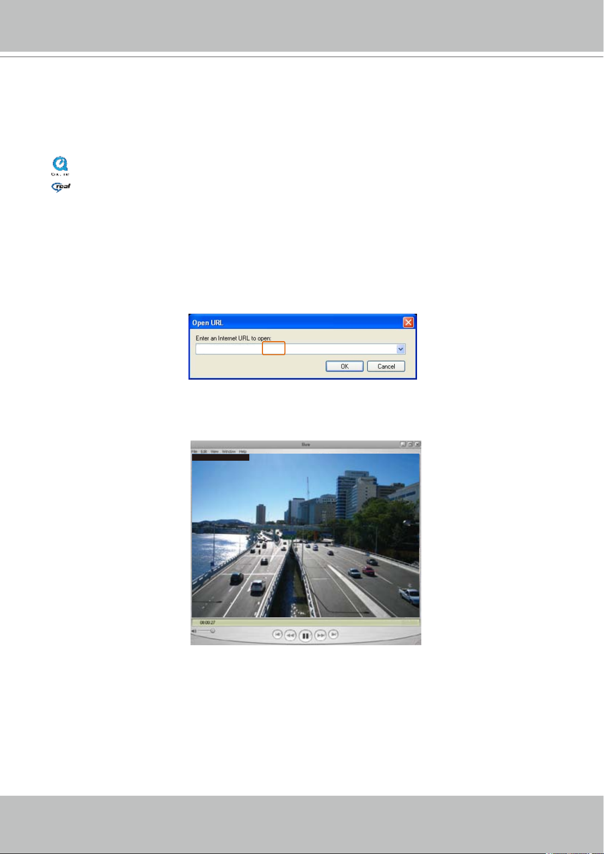
Using RTSP players
To view the MPEG-4 streaming media using RTSP players, you can use one of the following
players that support RTSP streaming�
Quick Time Player
Real Player
VLC media player
1� Launch a RTSP player�
mpegable Player
2. Choose File > Open URL. An URL dialog box will pop up.
3� The format is rtsp://<ip address>:<rtsp port>/<RTSP streaming access name for stream1 or
pvPlayer
stream2>
As most ISP and players only support port number 554 to allow RTSP streaming to go through,
please set the RTSP port to 554� For more information, please refer to RTSP Streaming on
page 38�
For example:
4� The live video will be displayed in your player�
For more information on how to configure RTSP access name, please refer to RTSP
Streaming on page 38 for details�
VIVOTEK - A Leading Provider of Multimedia Communication Solutions
14 - User's Manual
Video Mode MPEG-4
Frame size 176 x 144
Maximum frame rate 5 fps
Intra frame period 1S
Video quality (Constant bit rate) 40kbps
Audio type (GSM-AMR) 12.2kbps
rtsp://192.168.5.151:554/live.sdp
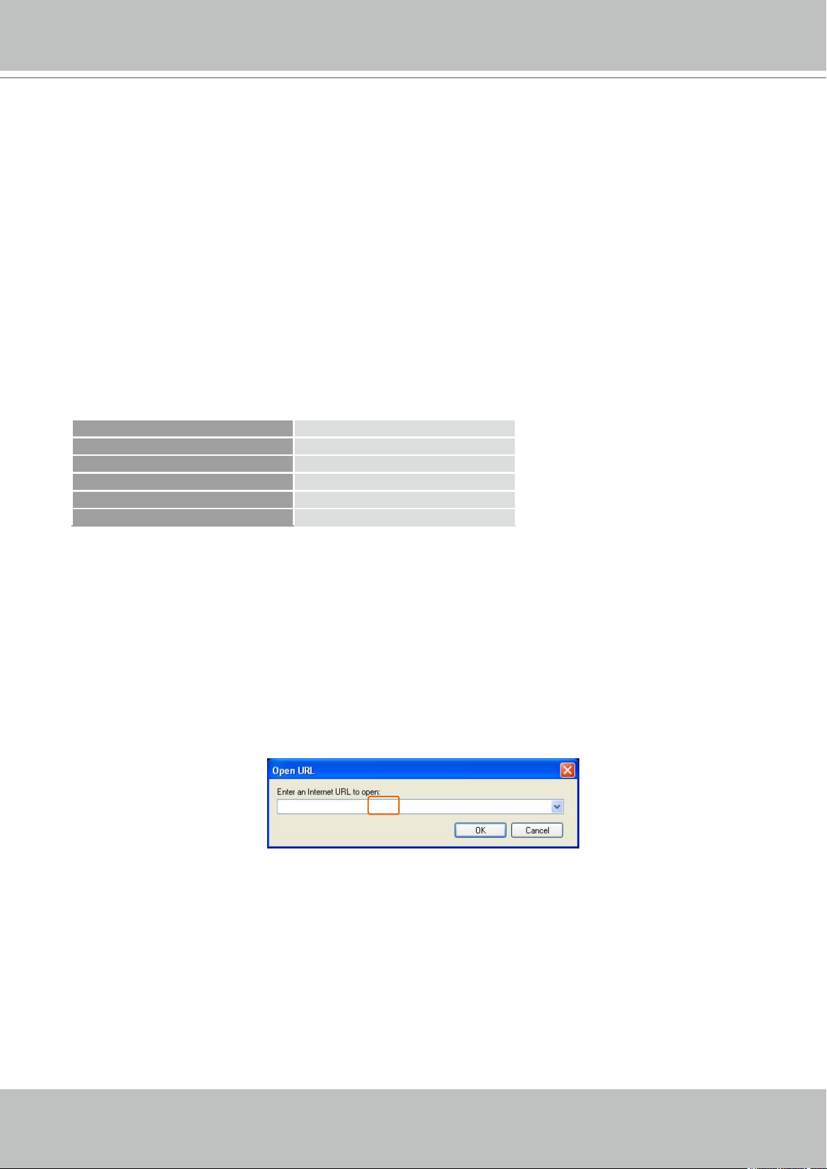
Using 3GPP-compatible mobile devices
To view the streaming media through 3GPP-compatible mobile devices, make sure the Network
Camera can be accessed from the Internet� For more information on how to set up the Network
Camera over the Internet, please refer to Setup the Network Camera over the Internet on page 7�
To utilize this feature, please check the following settings on your Network Camera:
1� Because most players on 3GPP mobile phones do not support RTSP authentication, make
sure the authentication mode of RTSP streaming is set to disable�
For more information, please refer to RTSP Streaming on page 38�
2. As the 3G network bandwidth is limited, you can’t use large video size. Please set the video
and audio streaming parameters as listed below�
For more information, please refer to Video on page 45�
3� As most ISP and players only support port number 554 to allow RTSP streaming to go
through, please set the RTSP port to 554� For more information, please refer to RTSP
Streaming on page 38�
4. Launch the players on 3GPP-compatible mobile devices (ex. Real Player).
5� Type the URL commands in the player�
The format is rtsp://<public ip address of your camera>:<rtsp port>/<RTSP streaming access
name for stream1 or stream2>�
For example:
VIVOTEK - A Leading Provider of Multimedia Communication Solutions
User's Manual - 15
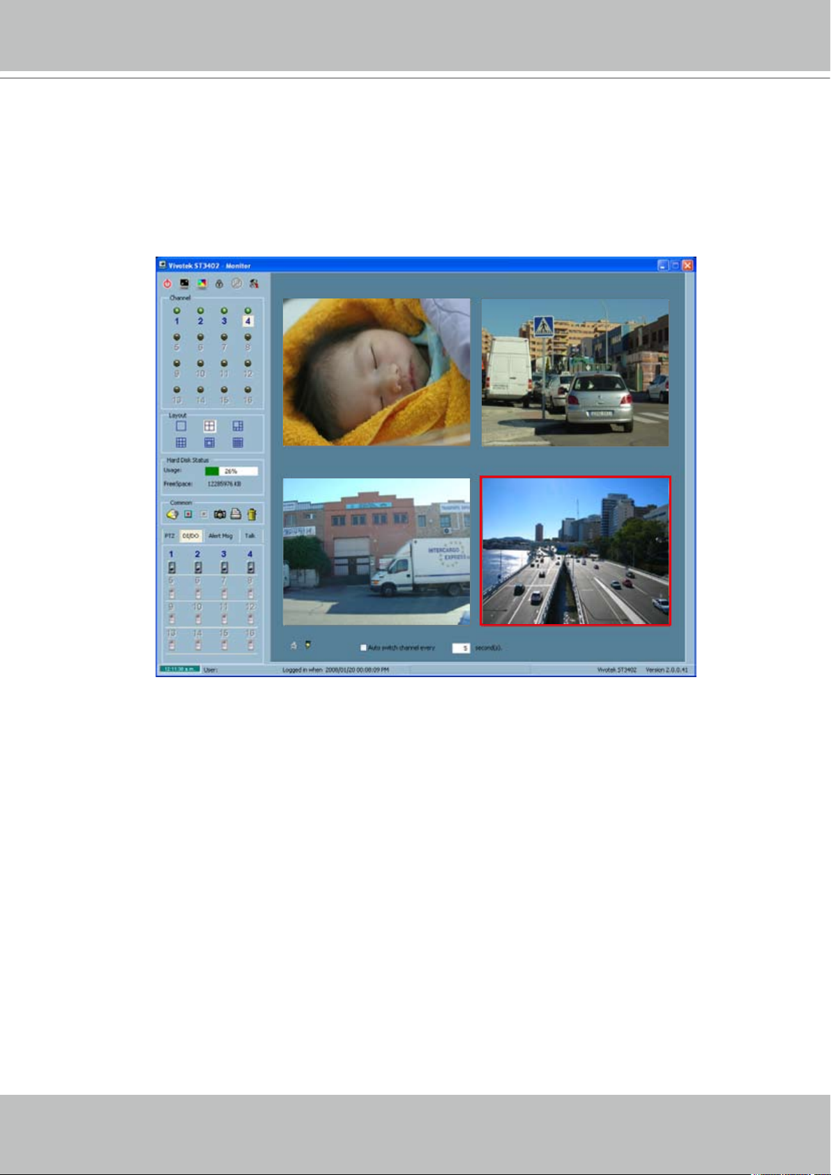
Using VIVOTEK recording software
The product software CD also contains recording software, allowing simultaneous monitoring
and video recording for multiple Network Cameras� Please install the recording software; then
launch the program to add the Network Camera to the Channel list� For detailed information
about how to use the recording software, please refer to the user’s manual of the software or
download it at http://www�vivotek�com�
VIVOTEK - A Leading Provider of Multimedia Communication Solutions
16 - User's Manual
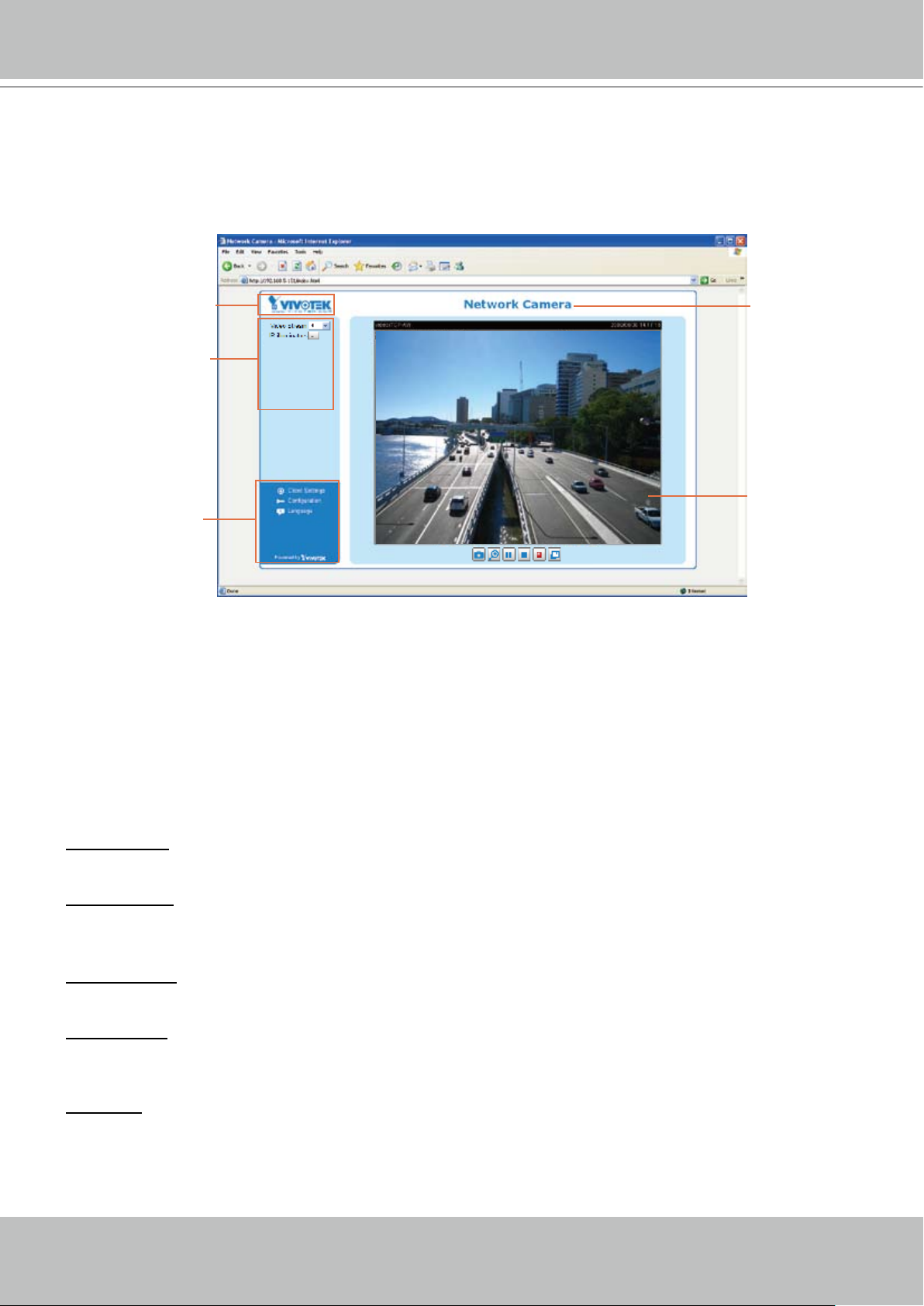
Logo of VIVOTEK INC.
Live view window
Camera control area
Configuration area
Host name
Main Page
This chapter explains the layout of the main page. It is composed of the following sections: Logo
of VIVOTEK INC�, Host name, Camera control panel, Menu, and Live video window�
Logo of VIVOTEK INC.
Click this logo to visit VIVOTEK website�
Host name
The host name can be customized to t your needs. For more information,
22�
Camera control area
Video Stream: This Network Camera supports MJPEG or MPEG-4 dual streams simultaneously. You can
select either one for live viewing�
IR illuminators: Click to turn on the IR LEDs for 20 seconds�
Conguration area
Client Settings: Click this button to access the client setting page� For more information, please refer to
Client Settings on page 19�
Conguration: Click this button to access the conguration page of Network Camera. It is suggested that
a password is applied to the Network Camera so that only the administrator can congure the Network
Camera� For more information, please refer to Conguration on page 21�
please refer to
System on page
Language: Click this button to choose a language for the user interface� Language options are available
in: English, Deutsch, Español, Français, Italiano,
日本語
, Português,
簡体中文
繁體中文
and
�
VIVOTEK - A Leading Provider of Multimedia Communication Solutions
User's Manual - 17
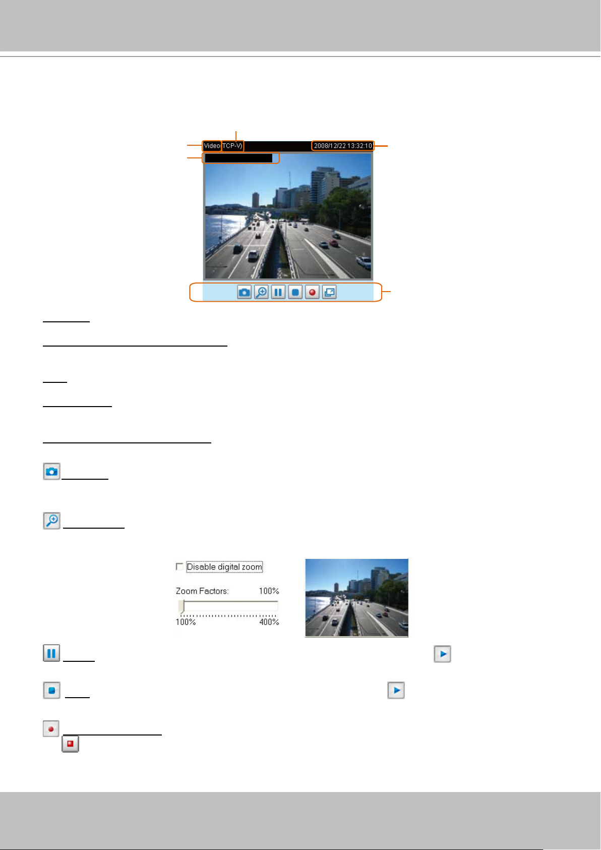
Video and audio control buttons
MPEG-4 protocol and media options
Video title
Time
Title and time
Video 13:32:10 2008/12/22
Live Video Window
■ The following window is displayed when the video mode is set to MPEG-4:
Video title:
The video title can be congured. For more information, please refer to Video settings on page 45�
MPEG-4 protocol and media options: The transmission protocol and media options for MPEG-4 video
streaming. For further conguration, please refer to Client Settings on page 19�
Time: Display the current time. For further conguration, please refer to Video settings on page 45�
Title and time: Video title and time can be stamped on the streaming video. For further conguration,
please refer to Video settings on page 45�
Video and audio control buttons: Depending on the Network Camera model and Network Camera
conguration, some buttons may not be available.
Snapshot: Click this button to capture and save still images� The captured images will be displayed in
a pop-up window� Right-click the image and choose Save Picture As to save it in JPEG (*.jpg) or BMP
(*.bmp) format.
Digital zoom: Click and uncheck Disable digital zoom to enable the zoom operation. The navigation
screen indicates which part of the image is being magnied. To control the zoom level, drag the slider
bar� To move to a different area you want to magnify, drag the navigation screen�
Pause: Pause the transmission of streaming media� The button becomes Resume button after
clicking the Pause button�
transmission�
the
stops accordingly� To specify the storage destination and the file name, please refer to MP4 Saving
Options on page 20 for details�
Stop: Stop the transmission of streaming media� Click the Resume button to continue
Start MP4 recording: Click this button to record video clips in MP4 le format to your computer. Press
Stop MP4 recording button to end recording� When you quit the web browser, video recording
VIVOTEK - A Leading Provider of Multimedia Communication Solutions
18 - User's Manual
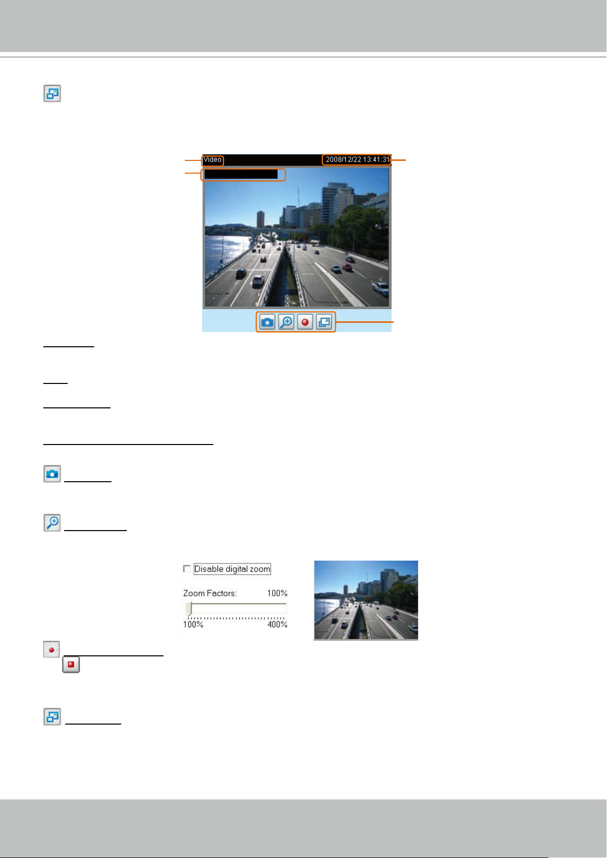
Time
Video title
Title and time
Video 13:41:31 2008/12/22
Video control buttons
Full Screen: Click this button to switch to full screen mode� Press “Esc” key to switch back to normal
mode�
■ The following window is displayed when the video mode is set to MJPEG:
Video title: The video title can be configured� For more information, please refer to Video settings on
page 45�
Time: Display the current time� For more information, please refer to
Video settings on page 45�
Title and time: Video title and time can be stamped on the streaming video� For more information, please
refer to
Video settings on page 45�
Video and audio control buttons: Depending on the Network Camera model and Network Camera
conguration, some buttons may not be available.
Snapshot: Click this button to capture and save still images� The captured images will be displayed
in a pop-up window� Right-click the image and choose Save Picture As to save it in JPEG (*.jpg) or BMP
(*.bmp) format.
Digital zoom: Click and uncheck Disable digital zoom to enable the zoom operation. The navigation
screen indicates which part of the image is being magnied. To control the zoom level, drag the slider
bar� To move to a different area you want to magnify, drag the navigation screen�
the
stops accordingly� To specify the storage destination and the file name, please refer to MP4 Saving
Options on page 20 for details�
mode�
Start MP4 recording: Click this button to record video clips in MP4 le format to your computer. Press
Stop MP4 recording button to end recording� When you quit the web browser, video recording
Full Screen: Click this button to switch to full screen mode� Press “Esc” key to switch back to normal
VIVOTEK - A Leading Provider of Multimedia Communication Solutions
User's Manual - 19
Client Settings
This chapter explains how to select the stream transmission mode and saving options at local
computer� When completed with the settings on this page, click Save on the page bottom to
take effect�
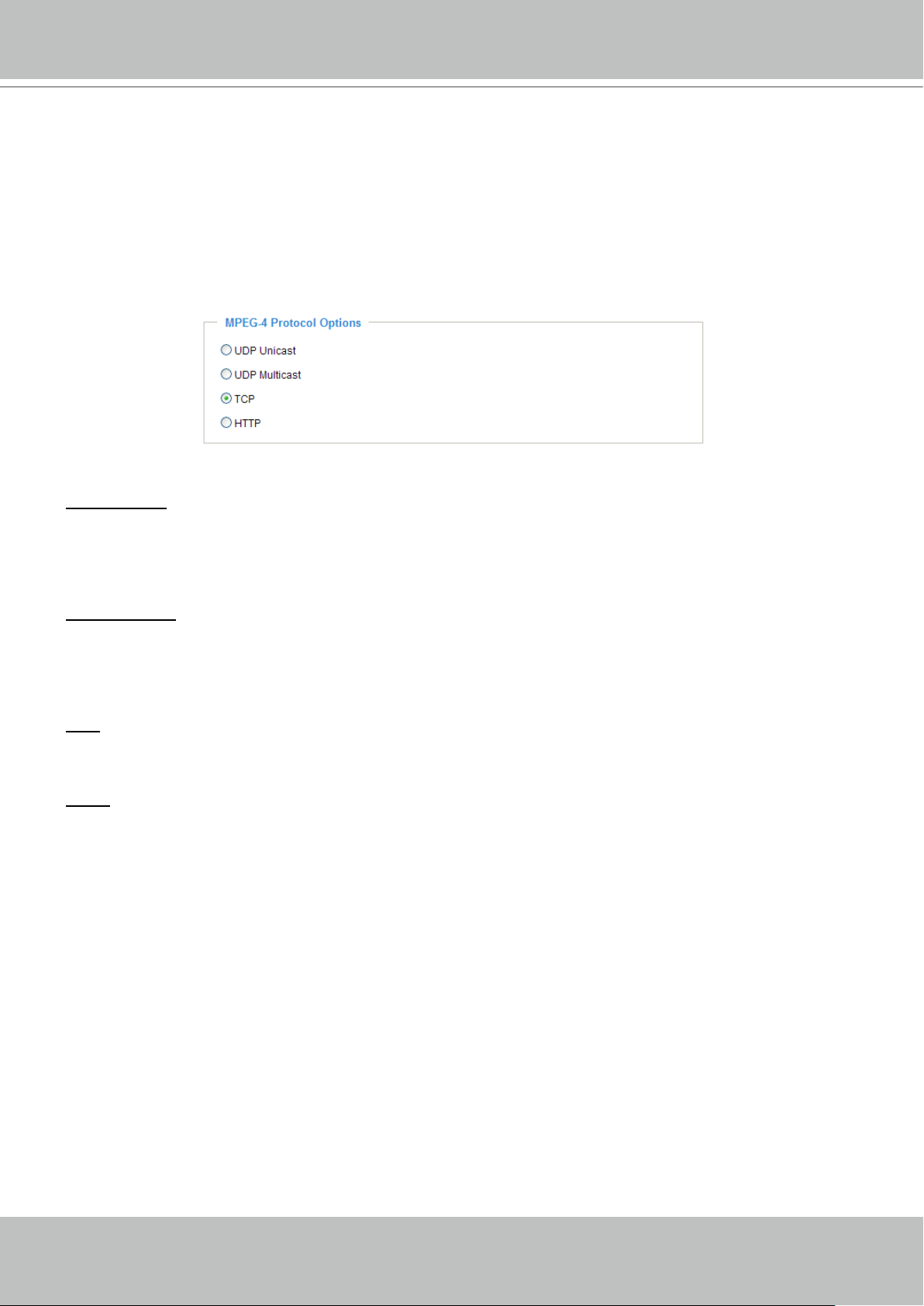
MPEG-4 Protocol Options
Depending on your network environment, there are four transmission modes of MPEG-4 streaming:
UDP unicast: This protocol allows for more real-time audio and video streams� However, network
packets may be lost due to network burst trafc and images may be broken. Activate UDP connection
when occasions require time-sensitive responses and the video quality is less important� Note that each
unicast client connecting to the server takes up additional bandwidth and the Network Camera allows up
to ten simultaneous accesses�
UDP multicast: This protocol allows multicast-enabled routers to forward network packets to all clients
requesting streaming media� This helps to reduce the network transmission load of the Network Camera
while serving multiple clients at the same time. Note that to utilize this feature, the Network Camera must
be configured to enable multicast streaming at the same time� For more information, please refer to
RTSP Streaming on page 38�
TCP: This protocol guarantees the complete delivery of streaming data and thus provides better video
quality� Nevertheless, the downside with this protocol is that its real-time effect is not as good as that of
the UDP protocol�
HTTP: This protocol allows the same quality as TCP protocol and you don’t need to open specic port
for streaming under some network environments. Users inside a rewall can utilize this protocol to allow
streaming data to come through�

VIVOTEK - A Leading Provider of Multimedia Communication Solutions
20 - User's Manual
CLIP_20080108-180853
Date and time suffix
The format is: YYYYMMDD_HHMMSS
File name prefix
MP4 Saving Options
Users can record the live video as they are watching it by clicking Start MP4 Recording on the main
page. Here, you can specify the storage destination and le name.
Folder: Specify a storage destination for the recorded video les.
File Name Prex: Enter the text that will be put in front of the video le name.
Add date and time sufx to the le name: Select this option to add date and time to the le name sufx.
VIVOTEK - A Leading Provider of Multimedia Communication Solutions
User's Manual - 21
Click to switch to Advanced mode
Firmware Version
Configuration list
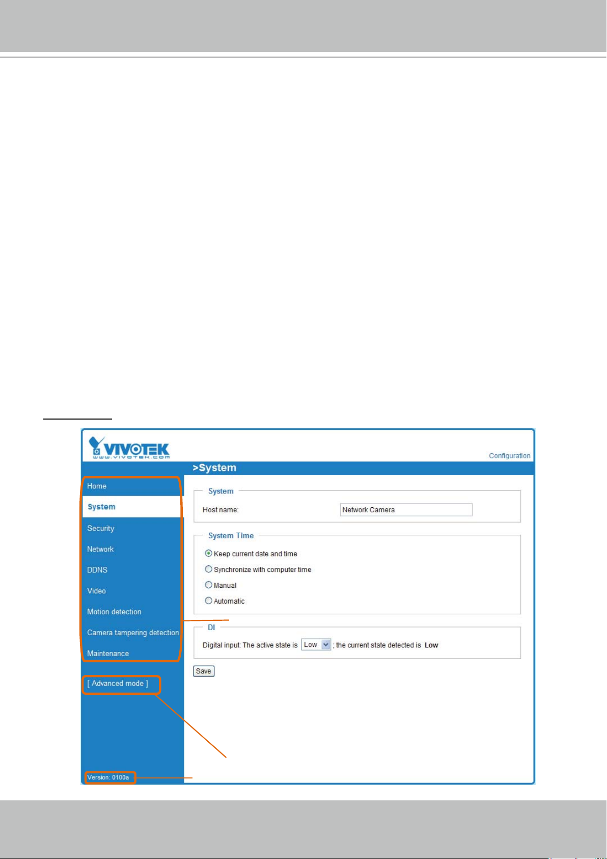
Conguration
Click Configuration on the main page will enter the camera setting pages� Note that only
Administrators can access the conguration page.
VIVOTEK offers an easy-to-use user interface that helps you setup your network camera without
much efforts� To simplify the setting procedure, VIVOTEK designs two kinds of user inferface-
-advanced mode for professional users and basic mode for entry-level users� Some advanced
functions (HTTPS/ Access list/ Homepage layout/ Application/ Recording/ System log/ View
parameters) won’t be displayed in basic mode�
If you want to set up advanced functions, please click [Advanced mode] on the bottom of the
conguration list to quickly switch to Advanced mode.
Another smart design to keep this user interface neat and easy to congure is that the detailed
information will be hidden unless you click on the function item� When you click on the first
function item, the detailed information of the first function item will be displayed; when you
click on the second function item, the detailed information of the second function item will be
displayed and that of the rst function item will roll up simultaneously.
Following is the interface of Basic mode and Advanced mode:
Basic mode
VIVOTEK - A Leading Provider of Multimedia Communication Solutions
22 - User's Manual
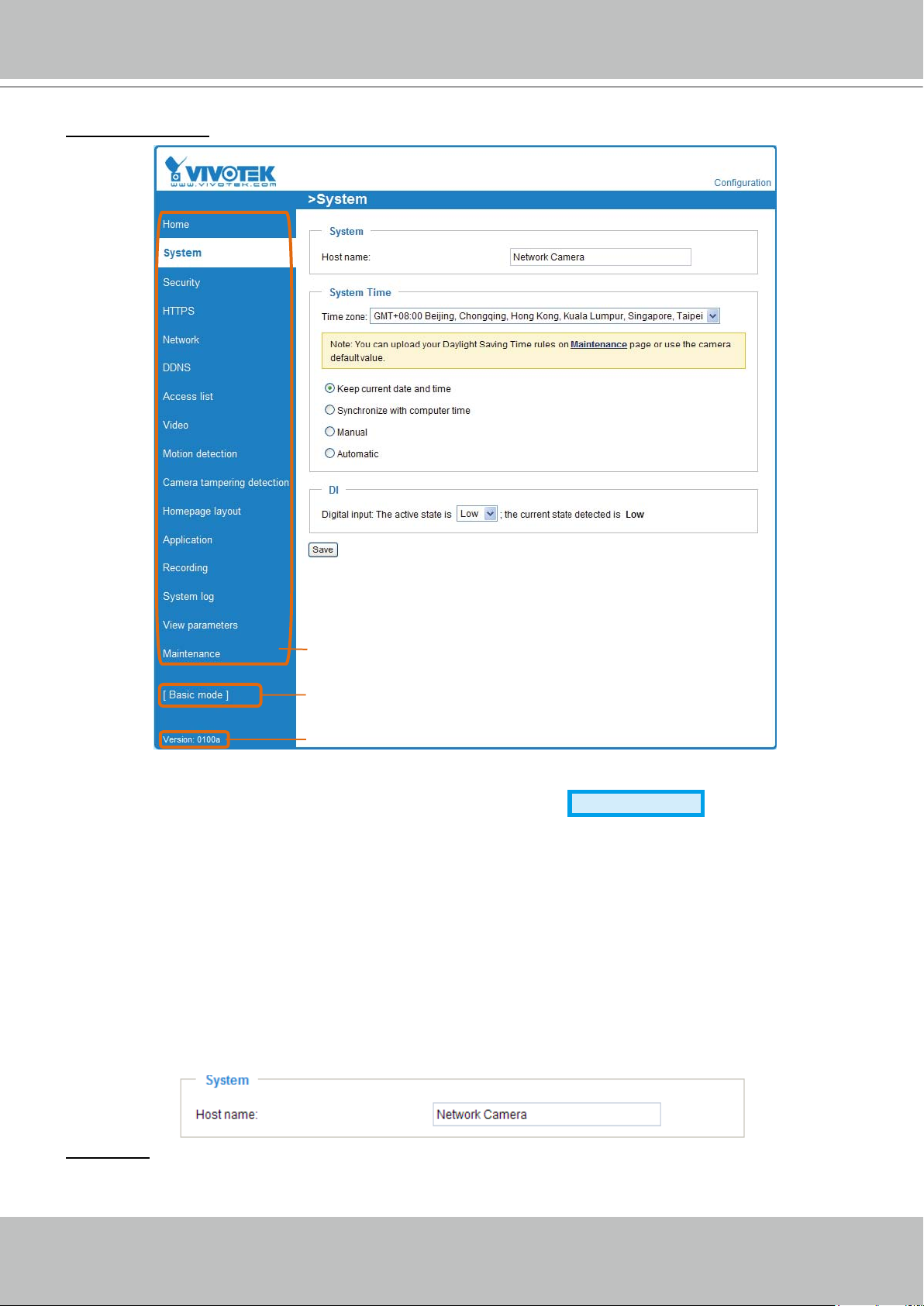
Click to switch to Basic mode
Firmware Version
Configuration list
Advanced mode
Each function on the configuration list will be explained in the following sections. Those
functions that only show in Advanced mode are marked with
Advanced mode
� If you want to set
up advanced functions, please click [Advanced mode] on the bottom of the conguration list to
quickly switch to Advanced mode�
System
This section explains how to congure the basic settings for the Network Camera, such as the
host name and system time� It is composed of the following three columns: System, System
Time and DI� When completed with the settings on this page, click Save on the page bottom to
take effect�
System
Host name: Enter a desired name for the Network Camera. The text will be displayed at the top of the
main page�
VIVOTEK - A Leading Provider of Multimedia Communication Solutions
User's Manual - 23
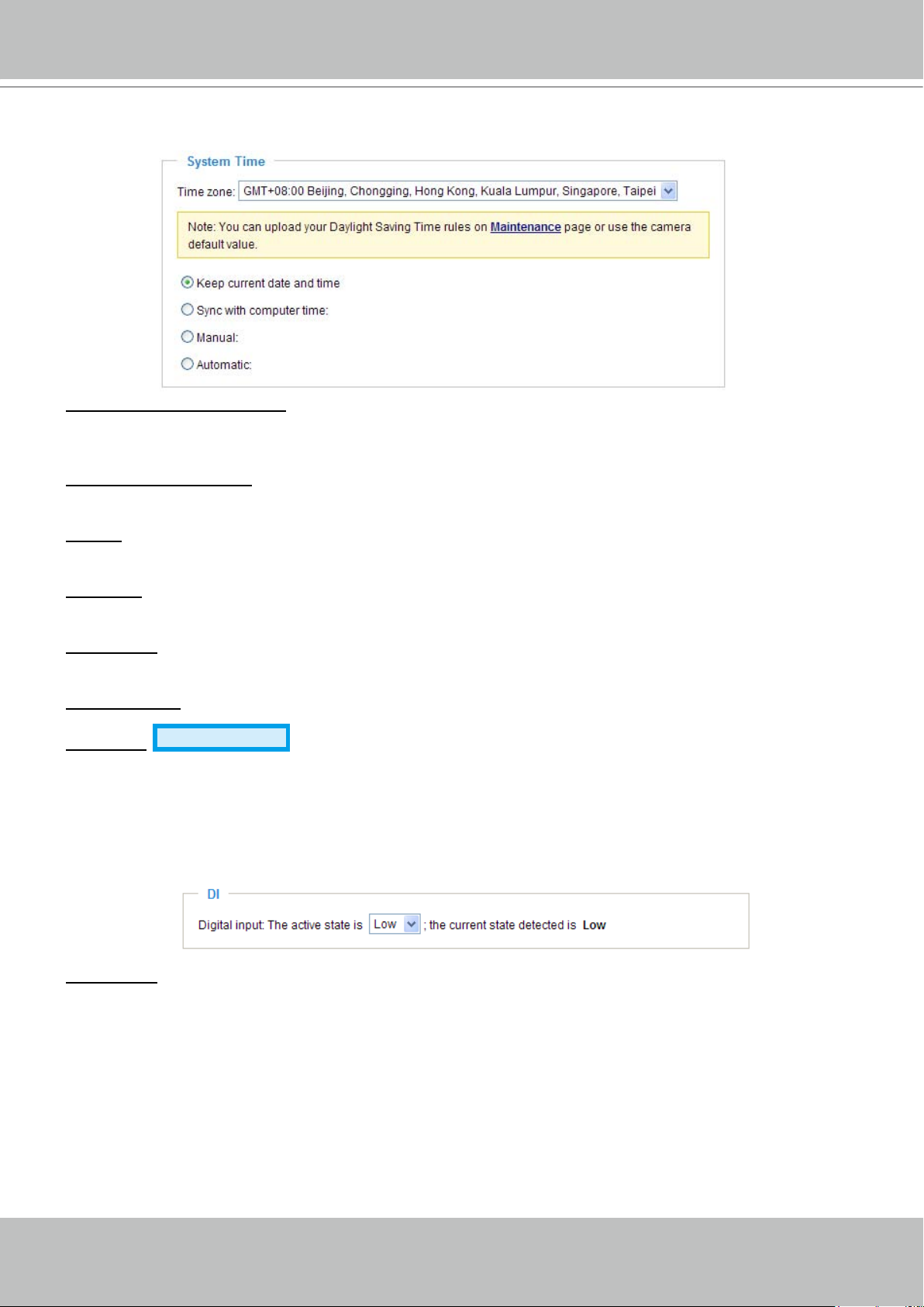
System Time
Keep current date and time: Select this option to reserve the current date and time of the Network
Camera� The Network Camera’s internal real-time clock maintains the date and time even when the
power of the system is turned off�
Sync with computer time: Select this option to synchronize the date and time of the Network Camera with
the local computer� The read-only date and time of the PC is displayed as updated�
Manual: The administrator can enter the date and time manually� Note that the date and time format are
[yyyy/mm/dd] and [hh:mm:ss]�
Automatic: The Network Time Protocol is a protocol serves synchronize computer clocks by periodically
querying an NTP Server�
NTP server: Assign the IP address or domain name of the time-server. Leaving the text box blank
connects the Network Camera to the default time-servers�
Update interval: Select to update the time with the NTP server on hourly, daily, weekly, or monthly basis�
Time zone
Advanced mode
: According to your local time zone, select one from the drop-down list. If
you want to upload the daylight saving time rules on Maintenance page, please refer to Upload / Export
Daylight Saving Time Conguration File on page 77 for details�
DI
Digital input: Select High or Low to dene normal status of the digital input. The Network Camera will
report the current status�
VIVOTEK - A Leading Provider of Multimedia Communication Solutions
24 - User's Manual
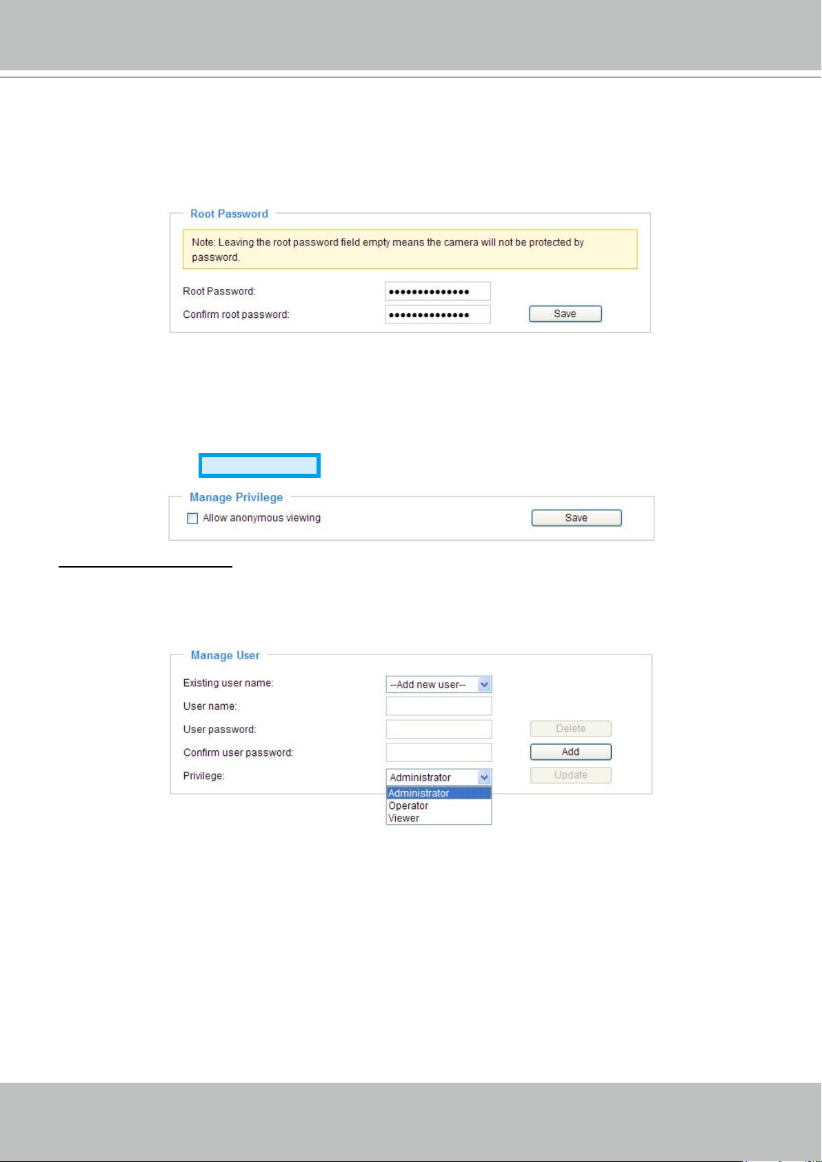
Security
This section explains how to enable password protection and create multiple accounts.
Root Password
The administrator account name is “root”, which is permanent and can not be deleted� If you want to add
more accounts in Manage User column, please apply a password for the “root” account rst.
1. Type the password identically in both text boxes, and click Save to enable password protection�
2� A window will be prompted for authentication; type the correct user’s name and password in related
elds to access the Network Camera.
Manage Privilege
Allow anonymous viewing: If you check this item, any clients can get access to the live streaming without
entering User ID and Password�
Advanced mode
Manage User
Administrators can add up to 20 user accounts�
1� Input the new user’s name and password�
2� Select the Privilege for new user account� Click Add to take effect�
Access rights are sorted by user privilege (Administrator, Operator, and Viewer)� Only administrators
can access the Configuration page� Though operators can not access the Configuration page, they
are capable of using the URL commands to get and set the value of parameters� For more information,
please refer to URL Commands of the Network Camera on page 80� Viewers can only access the main
page for live viewing�
Here you also can change user’s access rights or delete user accounts�
1. Select an existing account to modify.
2� Make necessary changes and then click Update or Delete to take effect�
VIVOTEK - A Leading Provider of Multimedia Communication Solutions
User's Manual - 25
HTTPS (Hypertext Transfer Protocol over SSL)
Advanced mode
This section explains how to enable authentication and encrypted communication over SSL
(Secure Socket Layer). It helps protect streaming data transmission over the Internet on higher
security level.
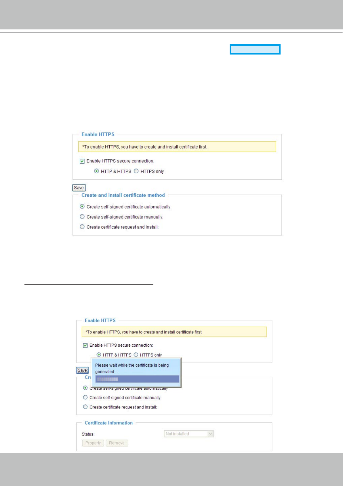
Enable HTTPS
Check this item to enable HTTPS communication, and then select a connection option: "HTTP & HTTPS"
or "HTTPS only". Note that you have to create and install certificate first in the second column before
clicking the Save button.
Create and Install Certificate Method
Before using HTTPS for communication with the Network Camera, a Certificate must be created first.
There are three ways to create and install certificate:
Create self-signed certificate automatically
1. Select this option.
2. In the first column, check Enable HTTPS secure connection, and then select a connection option:
“HTTP & HTTPS” or “HTTPS only”.
3. Click Save to generate certificate.
VIVOTEK - A Leading Provider of Multimedia Communication Solutions
26 - User's Manual
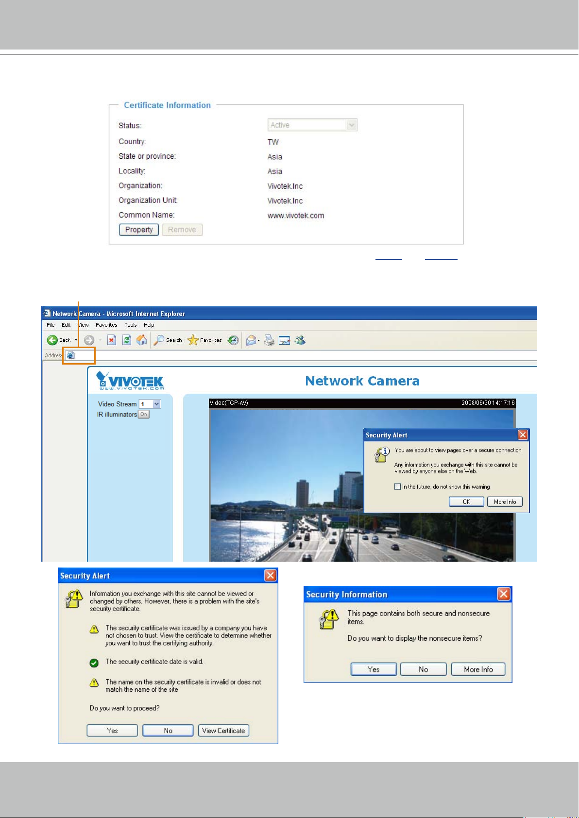
https://192.168.5.151/index.html
https://
4. The Certificate Information will automatically show up in the third column as below. You can click
Property to see the detailed information of the certicate.
5� Click Home to return to the main page� Change the address from “http://” to “https://“ on the Address
bar and press Enter on your keyboard� Some Security Alert dialogs will pop up� Click OK or Yes to
enable HTTPS�
VIVOTEK - A Leading Provider of Multimedia Communication Solutions
User's Manual - 27
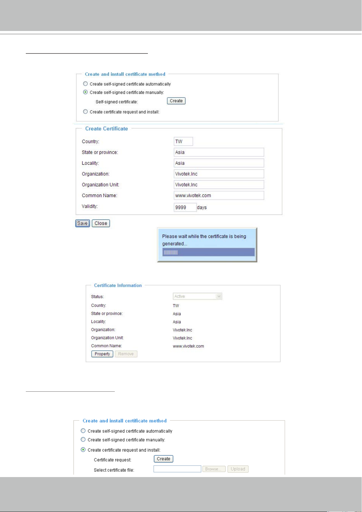
Create self-signed certificate manually
1� Select this option�
2� Click Create to open a Create Certicate page, and then click Save to generate the certicate.
3. The Certificate Information will automatically show up in the third column as below. You can click
Property to see the detailed information of the certicate.
4� Please refer to step 5� on last page�
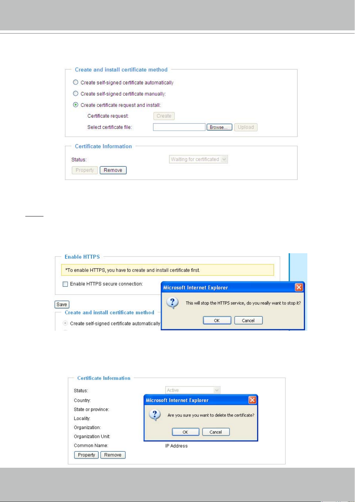
Create certificate and install : Select this option if you want to create an ofcial certicate issued by
a CA (Certicate Authority).
1� Select this option�
2� Click Create to open a Create Certicate page, and then click Save to generate the certicate.
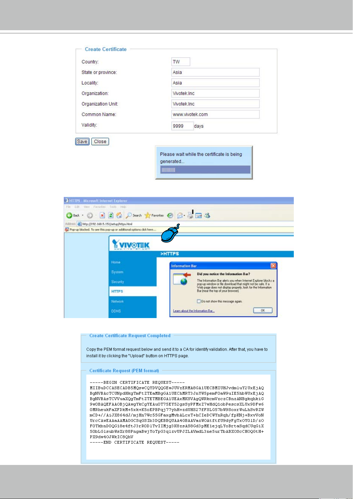
VIVOTEK - A Leading Provider of Multimedia Communication Solutions
28 - User's Manual
3� If you see the following Information Bar, click OK and the menu bar on the top of the page to allow the
Pop-ups�
4. The Pop-up window shows an example of a certicate request.
VIVOTEK - A Leading Provider of Multimedia Communication Solutions
User's Manual - 29
5� Look for a trusted certificate authority that issues digital certificates� Enroll the Create Certificate
Request, then wait for the certicate authority to issue a SSL certicate. When the signed certicate is
returned, click Browse... to search for the issued certicate, then click Upload in the second column�
6� Please refer to step 4� and 5� on page 26�
NOTE
► How to cancel HTTPS settings?
1� Uncheck Enable HTTPS secure connection in the rst column and then click Save, then a warning
dialog will pop up�
2� Click OK to disable HTTPS�
3� The webpage will
redirect to non-https page automatically�
► If you want to create and install other certificate, please remove the existing one. To remove the
signed certificated, uncheck the Enable HTTPS secure connection in the first column and click
Save� Then click Remove to erase the certicate.
VIVOTEK - A Leading Provider of Multimedia Communication Solutions
30 - User's Manual
Network
This section explains how to congure wired network connection for the Network Camera.
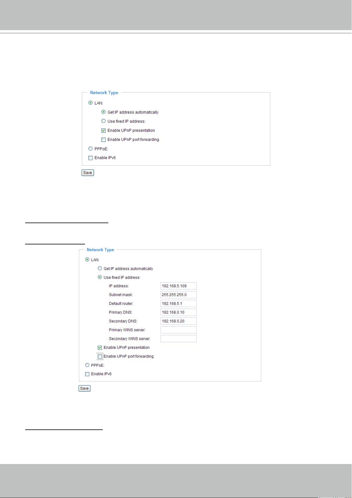
Network Type
LAN
Select this option when the Network Camera is deployed in a local area network (LAN) and is intended
to be accessed by local computers� The default setting of Network Type is LAN� Remember to click Save
when you complete the Network setting�
Get IP address automatically: Select this option to obtain an available dynamic IP address assigned by a
DHCP server each time the camera is connected to the LAN�
Use xed IP address: Select this option to manually assign a static IP address to the Network Camera�
1. You can make use of VIVOTEK installation wizard II on the software CD to easily set up the Network
Camera in LAN� Please refer to Software installation on page 10 for details�
2� Enter the static IP, Subnet mask, Default router, Primary DNS provided by your ISP�
TM
Enable UPnP presentation: Select this option to enable UPnP
presentation for your Network Camera
so that whenever a Network Camera is presented to the LAN, shortcuts of connected Network Cameras
will be listed in My Network Places. You can click the shortcut to link to the web browser. Currently,
TM
UPnP
UPnP
is supported by Windows XP or later. Note that to utilize this feature, please make sure the
TM
component is installed on your computer�
 Loading...